Development of Environmental Long Range RFID Sensors Based on the Modulated Scattering Technique


Department of Information Engineering and Computer Science, University of Trento, 38100 Trento, Italy
*
Author to whom correspondence should be addressed.
Electronics 2018, 7(7), 106; https://doi.org/10.3390/electronics7070106
Submission received: 31 May 2018
/
Revised: 25 June 2018
/
Accepted: 29 June 2018
/
Published: 4 July 2018
(This article belongs to the Special Issue Unconventional RFID Systems)
Abstract
:This work presents the development of a wireless sensor system for environmental monitoring based on the modulated scattering technique (MST). The MST sensor probes are based on the scattering properties of small passive antennas and radiate part of the impinging electromagnetic field generated by an interrogating antenna, which also acquires the backscattered signal as information. The MST probes are able to deliver data without radio frequency front end. They use a simple circuit that alternatively terminates the antenna probe on suitable loads to generate a low modulation signal on the backscattered electromagnetic wave. In this work, the MST sensor system for environmental monitoring has been proposed to obtain the best performance in communication range, load efficiency and power harvesting. The MST sensor has been fabricated and assessed in practical scenarios. The proposed prototype, able to operate in X band at 10 GHz and able to provide a communication range of about 15 m, serves as a proof-of-concept. The acquired measurements demonstrate that the prototype is able to measure accurately and send data without radio frequency front end or bulky wired connection with the same efficiency of standard wireless sensors such as radio frequency identifier (RFID) or wireless sensor networks (WSN).
1. Introduction
In the past few years, the demand for sensors that are low cost and have the capability to work in multi-function wireless environments has grown. The data collected from the sensors must be elaborated and transmitted related to a given environmental parameter [1]. The advantage of this sensor is evident especially in critical scenarios such as after natural disasters with restricted or dangerous areas [2].
Furthermore, they are very beneficial for practical purposes like homeland security [3], rescue operation and law enforcement services. Wireless sensor networks [4,5] (WSNs) have been successfully adopted for the advancement of long-range estimation systems, but they use dense frequency bands and require maintenance and complex communication protocols. Radio frequency identification systems (RFID) [6,7] are another type of wireless system that have been successfully used to track foods and goods. Now, they are widely used in many practical scenarios such as supermarkets and stores [8,9,10,11,12,13,14,15,16,17,18,19,20,21,22,23,24,25]. The main benefit of adopting an RFID system is the long life and low cost, but it requires a close proximity between the reader and tag. Therefore, for a long-range communication system, it would not be suitable. Another drawback of RFID is the difficulty in providing environmental probes directly on the RFID tags. To overcome this kind of issue, in [26,27,28], the modulated scattering technique (MST) was defined. The MST provides an alternative solution to the WSN and RFID technologies’ disadvantages. The MST probes use the scattering properties of small passive antennas as in [29,30], and because of this, they do not require a physical connection with the measurement system. MST systems do not rely on the sensitivity of the antenna tag, nor its load with respect to the relevant quantity to be sensed, like standard RFID sensors. The signal is delivered toward the MST reader, and it is insensitive to propagation effects. On the contrary, RFID sensors’ performances are strongly sensitive to propagation effects, since they are impedance-based devices. In particular for RFID systems, as in [31], electromagnetic propagation problems like reflections, interferences, propagation losses and collision problems [32,33] are more important. Furthermore, the RFID is able to demodulate the signal accurately and give the answer only if examined correctly. For this reason, a local oscillator, an antenna driver, a demodulator and a data encoder are required in a standard RFID transceiver. The MST tag sends the information by modulating the impinging electromagnetic wave, without doing any operations like demodulation. Therefore, in complex scenarios, the RFID-based system would not work accurately. Moreover, RFID systems work in a very short range, while MST systems can work in free space, near-field, as well as far-field scenarios, and the operative range r can be evaluated simply by considering the radar equation, as in [34]. In particular, the MST probe antenna has different loads. These loads change by means of a suitable electronic switch. The change of antenna impedance in an MST reader introduces a low-frequency modulation signal in a backscattered electromagnetic wave, as in [27,30], and also, it reads the backscattered field. The information is retrieved from the low-frequency modulation signal provided by the tag to the backscattered wave. A radio frequency front end is not required for the MST tags. After interactions with the MST tag reader, it generates an electromagnetic wave, which carries the information. The absence of RF front end makes the tag less expensive and suitable for a small probe to reduce perturbations and noise measurements. The MST probes have been used successfully in applications like, microwave imaging [35,36], measurements in near-field electromagnetics [37,38,39,40,41,42], characterization of materials [43,44] and other applications, as given in [45,46,47,48]. In this work, an X band wireless MST monitoring system is proposed for environmental monitoring. The prototype requires only a limited amount of power and ensures a good communication range of about 15 m. It represents a good alternative to standard WSN- or RFID-based architecture. The proposed wireless sensor tag presents the following innovations: the operative frequency located in the X band at 10 GHz permits strongly reducing the tag and reader antenna dimensions. Higher frequency bands can be used to further reduce the sensor size and improve the signal bandwidth. Most of the state of the art long-range RFID tag systems work on crowed frequency bands such as WiFi at 2.45 GHz, and most of them are not passive devices, since they make use of the WiFi module [49]. The proposed system does not need RF or microwave front-ends; moreover, with respect to the other commercial or experimental devices, it is theoretically able to reach distances up to kilometers [14,27]. Thanks to these characteristics, these sensors are particularly suitable to monitoring environmental parameters during natural disasters, such as earthquakes or avalanches. A three-month measurement campaign has been carried out to evaluate the proposed MST environmental monitoring systems. In particular, meteorological quantities, namely the temperature variations and humidity, were measured during the summer season in Northern Italy.
2. Mathematical Formulation
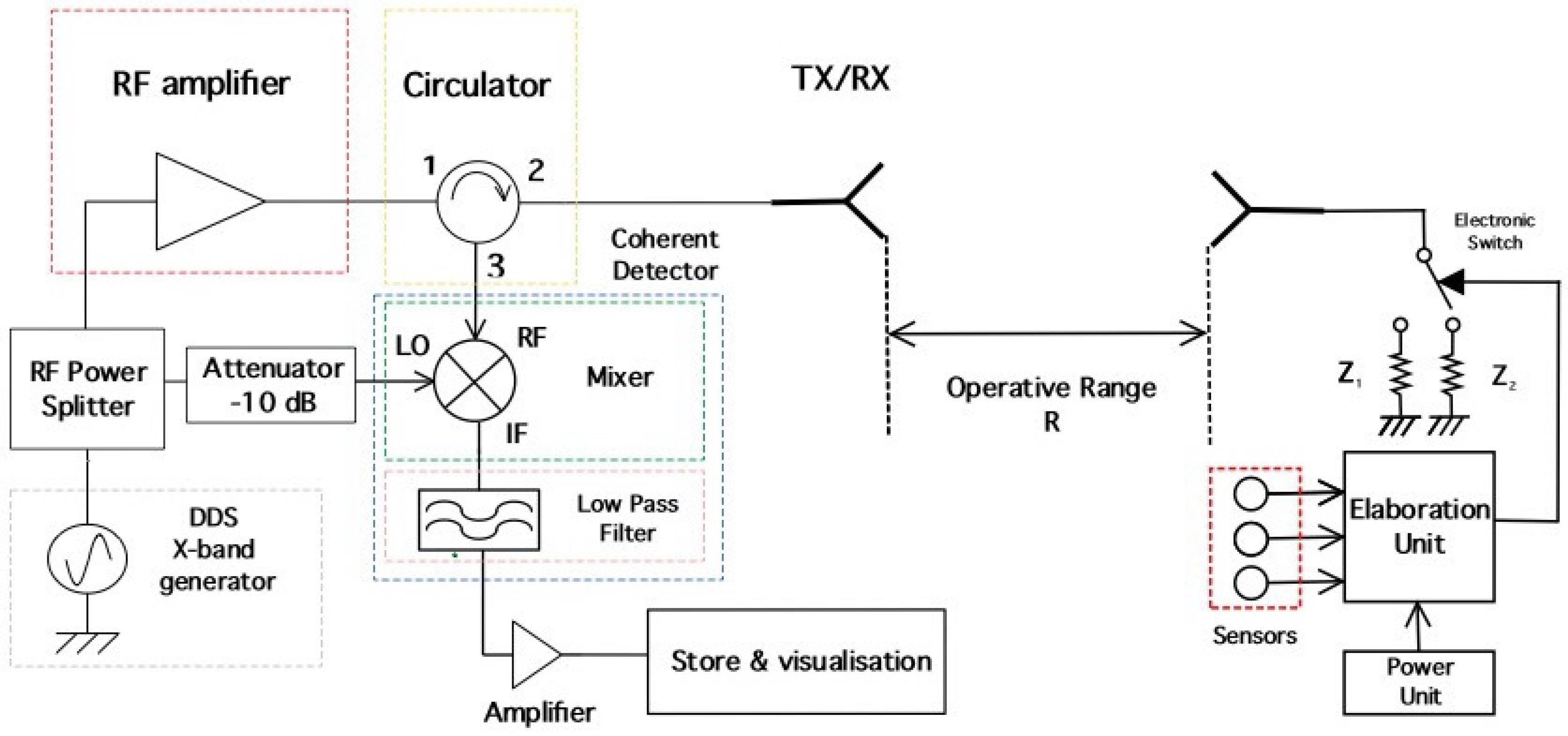
The schema of a mono-static MST measurement system is shown in Figure 1. It consists of a reader aimed at communicating with a remote tag placed far away from the reader at a distance r called the communication range. The tag could be equipped with different environmental probes. The reader is composed of a sinusoidal signal generator, a microwave low noise amplifier, a homodyne detector, a circulator and a high gain antenna. The circulator is used to consider only one high gain antenna, acting both as transmitter and receiver. The reader not only generates the electromagnetic wave, which impinges on the MST tag, but it also collects the back-scattered electromagnetic wave, which carries the information reflected by the tag. The homodyne detector is mandatory to correctly retrieve the information from the backscattered electromagnetic wave [50,51]. In particular, the high-frequency signal is converted to the baseband, and a suitable elaboration system is aimed at collecting, processing and storing the information from the low modulation signal of the backscattered wave [27]. On the left side of Figure 1 is shown the tag structure. The MST tag is composed of a small receiving antenna, an electronic switch, a set of loads, an elaboration unit, power units and a set of environmental probes. The elaboration unit reads the measured quantities from the probe. The elaboration units also act on the electronic switch; it permits connecting the antenna tag toward two different loads. The variation of impedance, connected with the antenna tag, produces a low-frequency modulation on the back-scattered electromagnetic wave. The low-frequency modulation carries the information, and it can be easily read by the reader. A good MST system design permits maximizing the communication range r [30]. This goal can be accomplished by considering the well-known radar equation reported in the following relation [34,52] (under the hypothesis of free space and far-field conditions):
where and are the power of the sinusoidal generator and the reader receiving antenna gain, respectively. is the minimum detectable power, and it depends on the receiver sensibility. and are the antenna tag aperture cross-section and gain, and is the wavelength of the sinusoidal signal generated by the reader. The quantity of ME, called the modulation efficiency, is reported in the following relation:
where is the antenna tag impedance and and are the two loads connected to the electronic switch. As can be noticed from Equation (2), the modulation efficiency ranges between and . Considering Equation (1), it is quite evident that the only way to improve the communication range r is to act on the values of the two loads and or to modify the antenna tag impedance . The other parameters are fixed quantities. To obtain the maximization of the ME, the best values for the two loads are and . is called the adsorbing load, and it is used to obtain a perfect match.
3. Description of the MST Environmental System
The following sub-sections are aimed at the description of the reader, MST tag structure and transmission protocol.
3.1. Reader Description
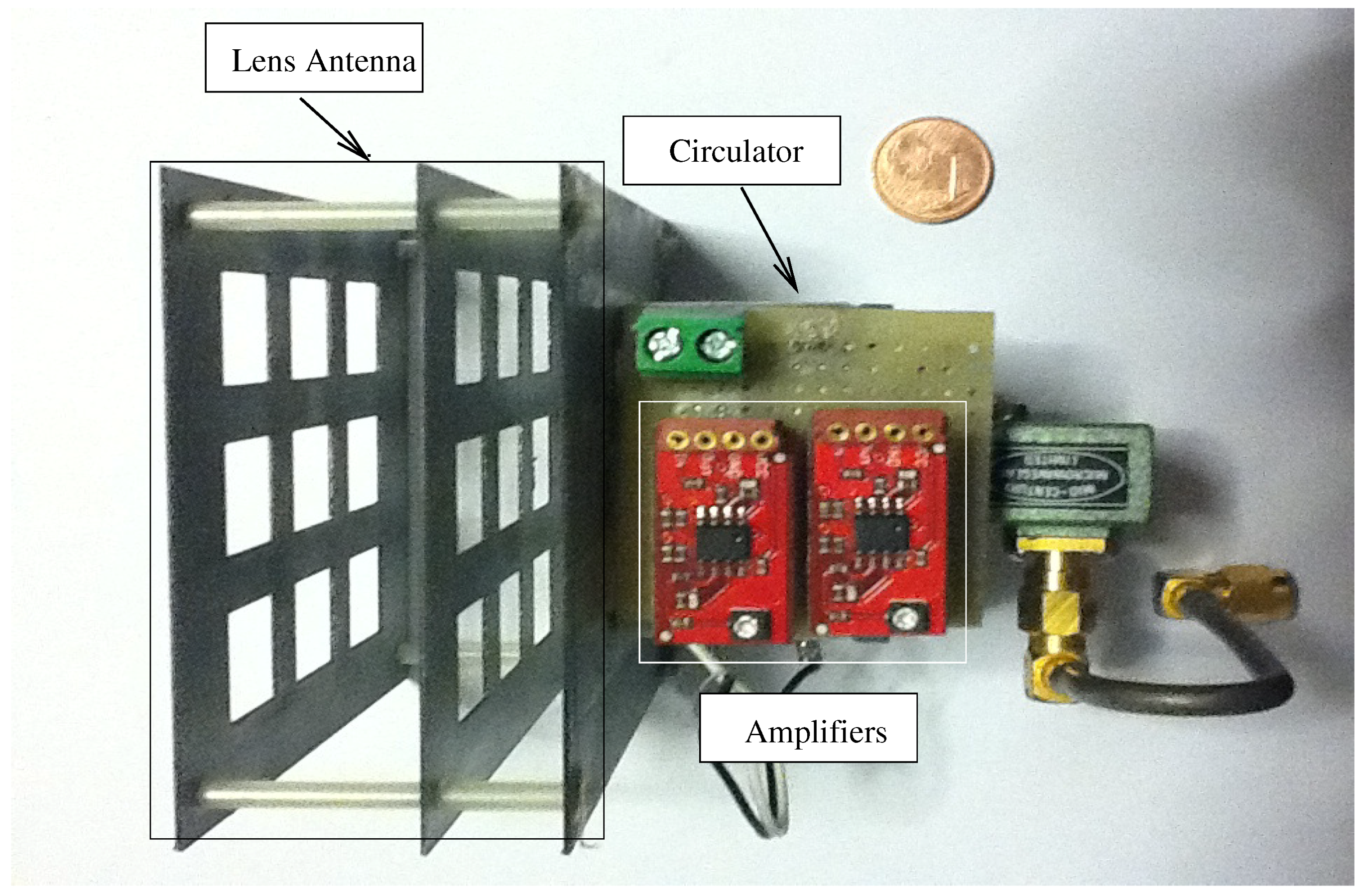
In Figure 2, the picture of the MST reader’s working prototype is shown. The prototype consists of a ferrite circulator, an X band microwave Gunn generator of mW, a lens antenna characterized with a gain of dBi and two low-frequency amplifiers with a total gain of dB. As can be noticed from Figure 2, the reader is a classical mono-static structure (characterized by only one antenna, which acts as a receiver and transmitter at the same time). The reader is quite compact and mechanically robust. The ferrite circulator output is connected to the homodyne receiver. The receiver is composed of an unequal splitter aimed at providing the reference to the mixer, a low-cost monolithic microwave integrated circuit mixer (an anadigics AKD12000). The signal at the mixer output is then filtered by means of a low pass seven order equal ripple -dB filter. The low modulation signal is extracted from the high frequency backscattered wave using a coherent detector. Further, the two low noise amplifiers are used to amplify the obtained baseband signal, where the amplifier has a total gain of dB. The least detectable power is about dBm at the reader output.
3.2. MST Tag Description
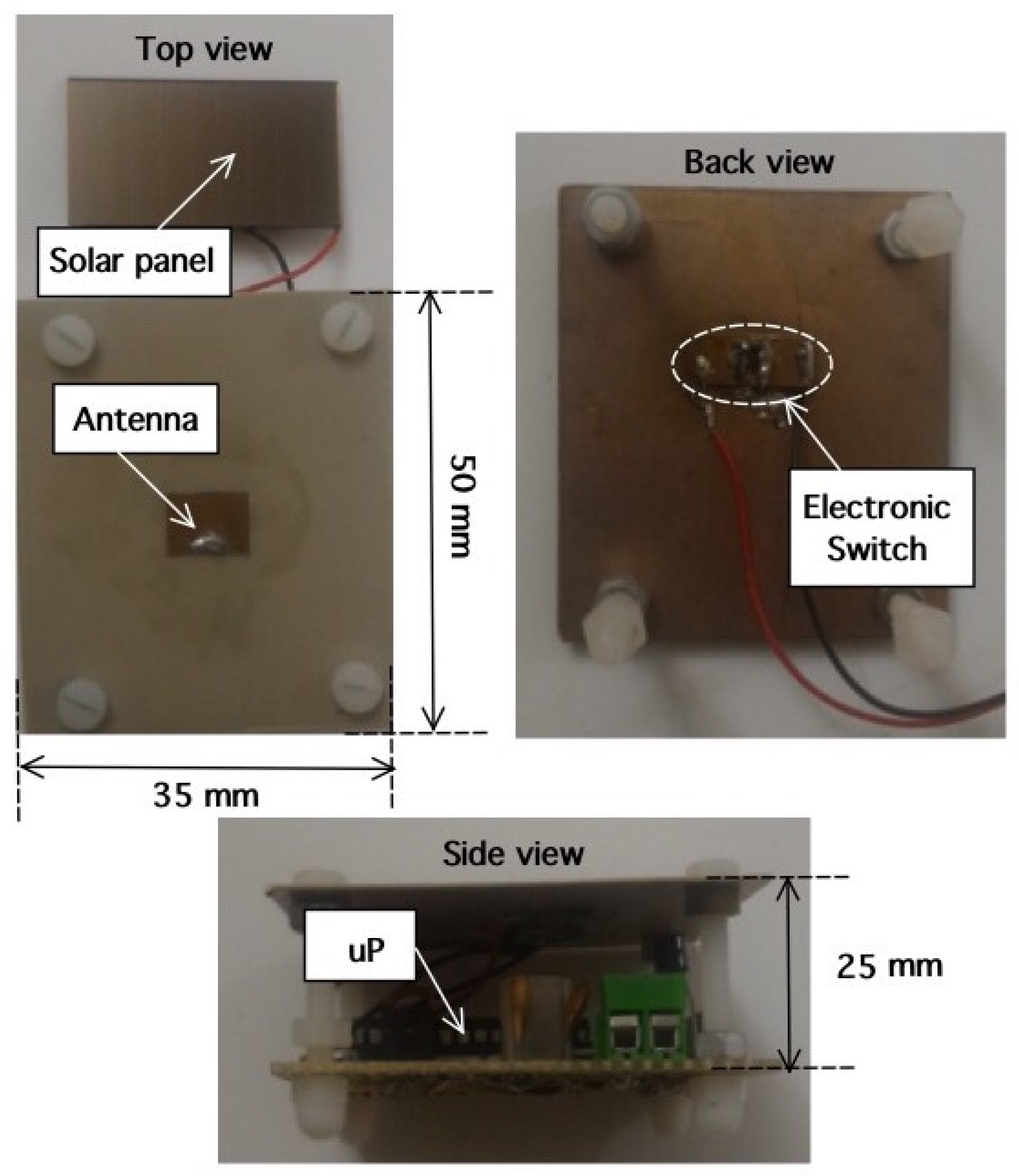
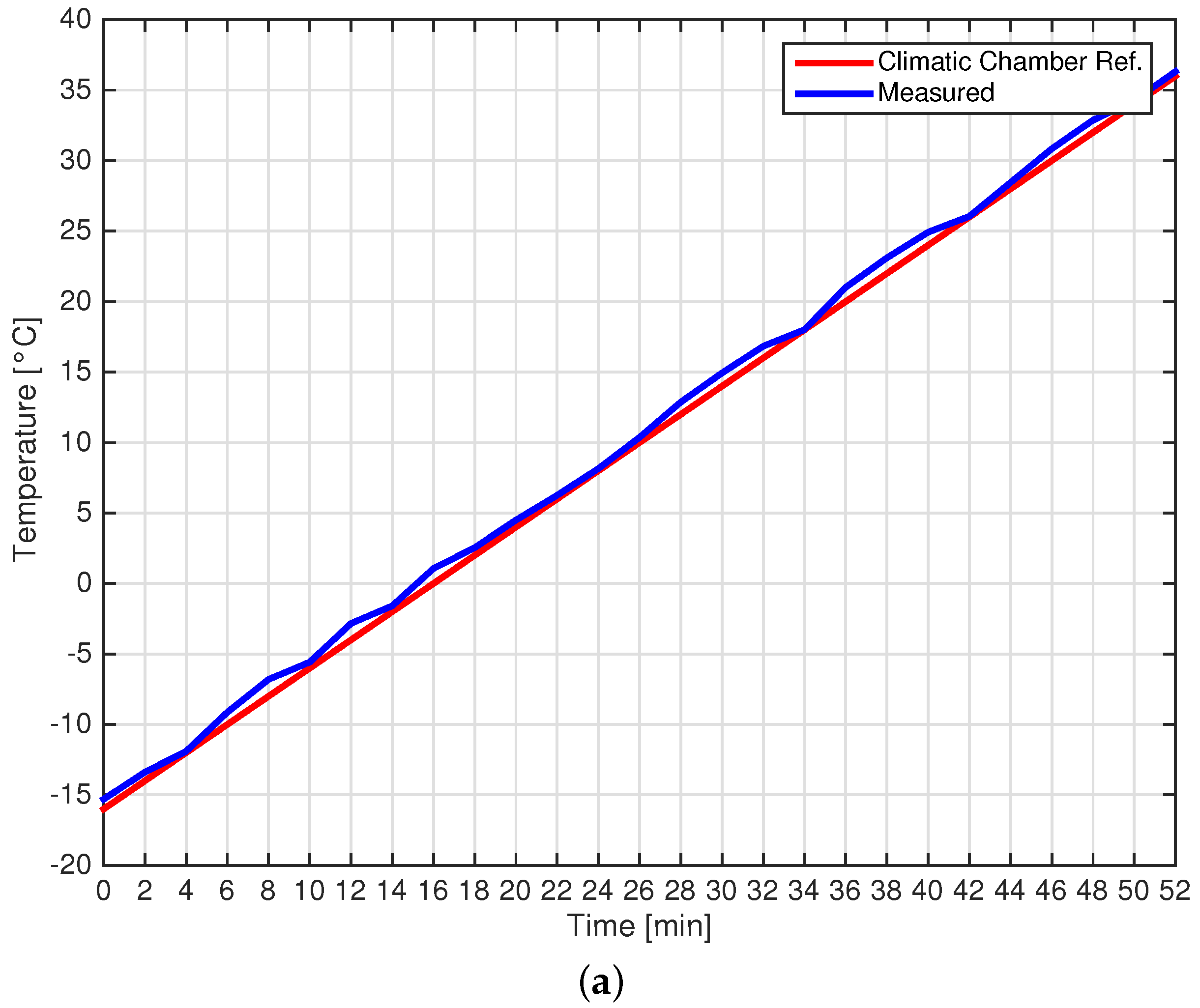
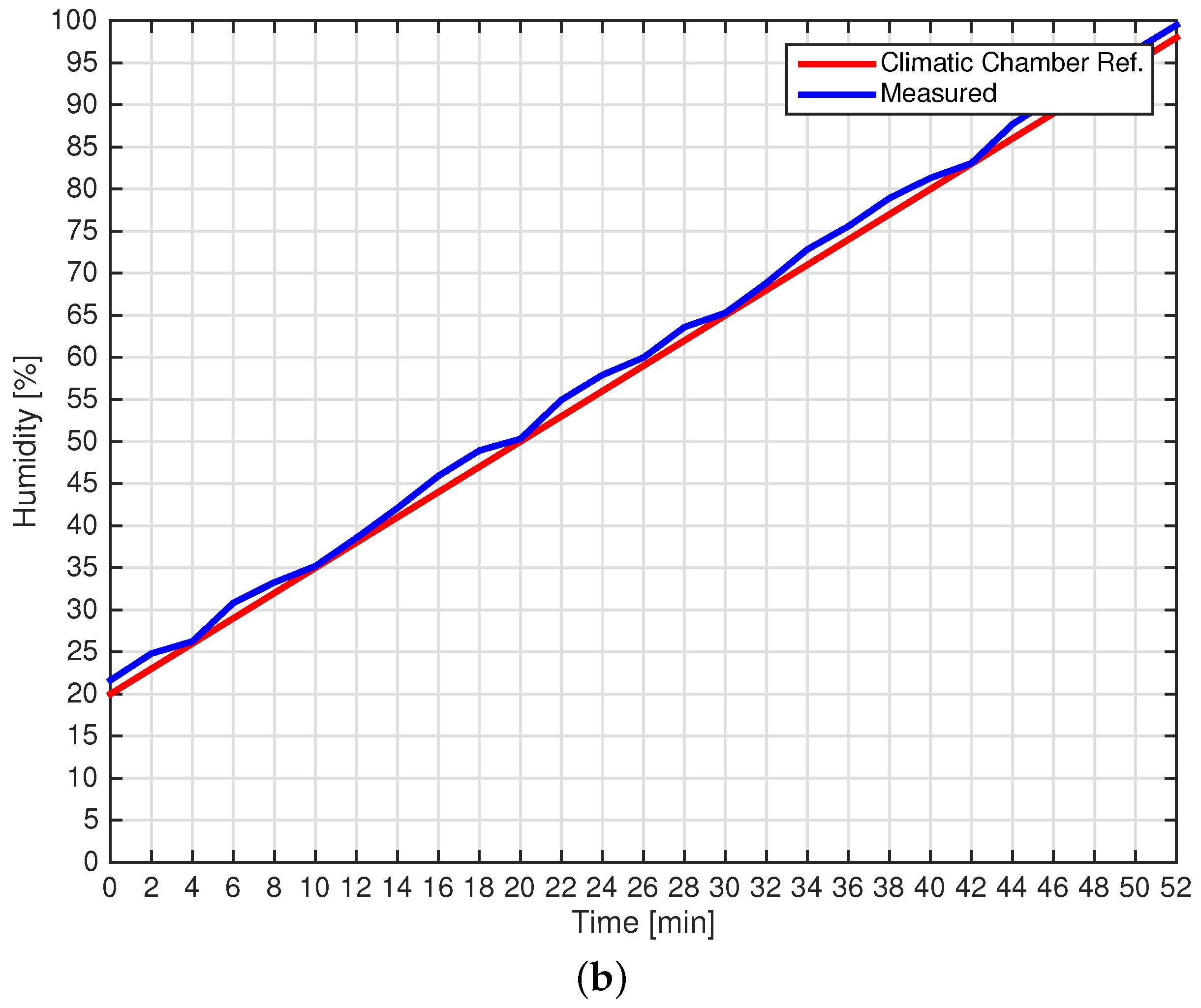
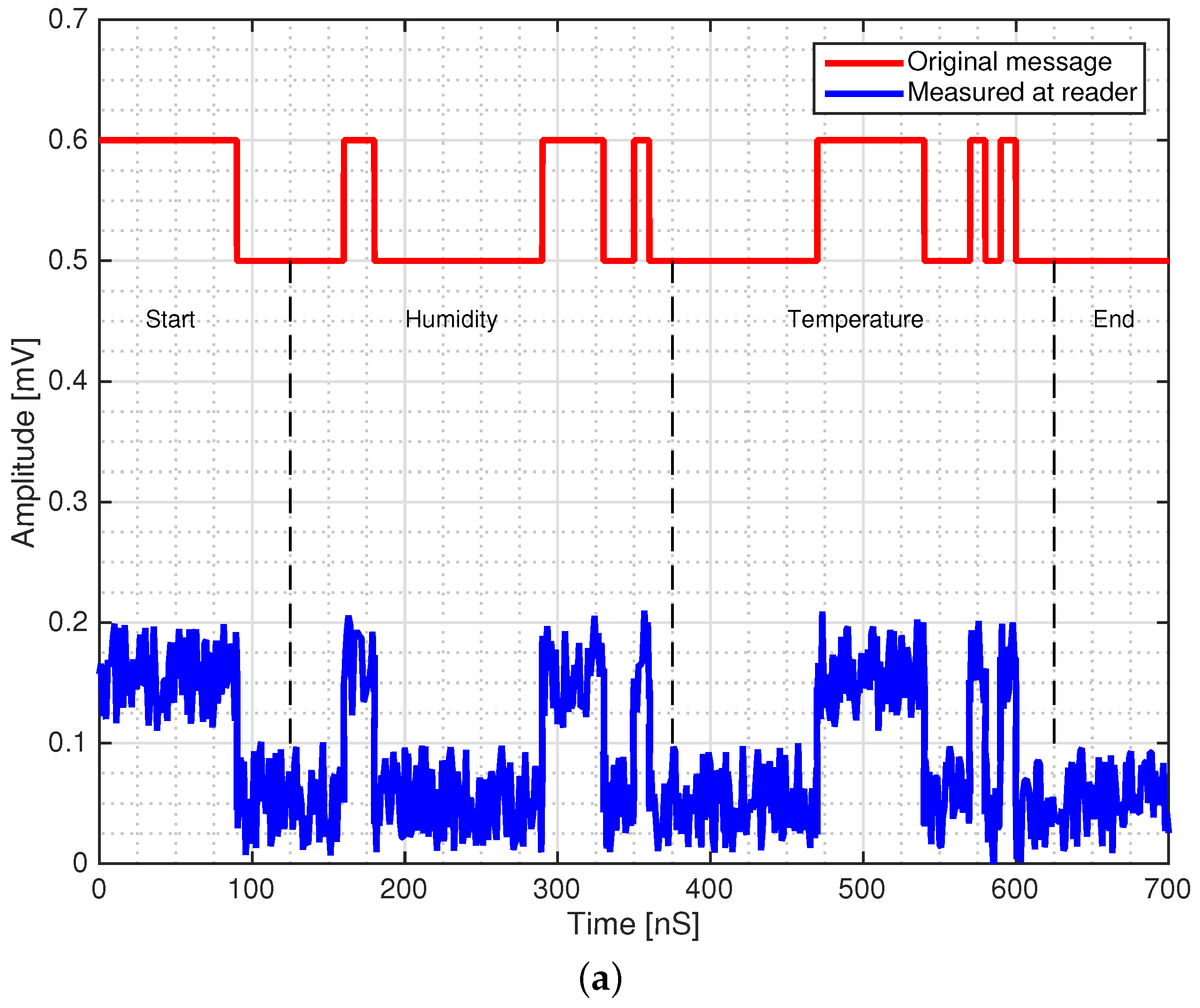
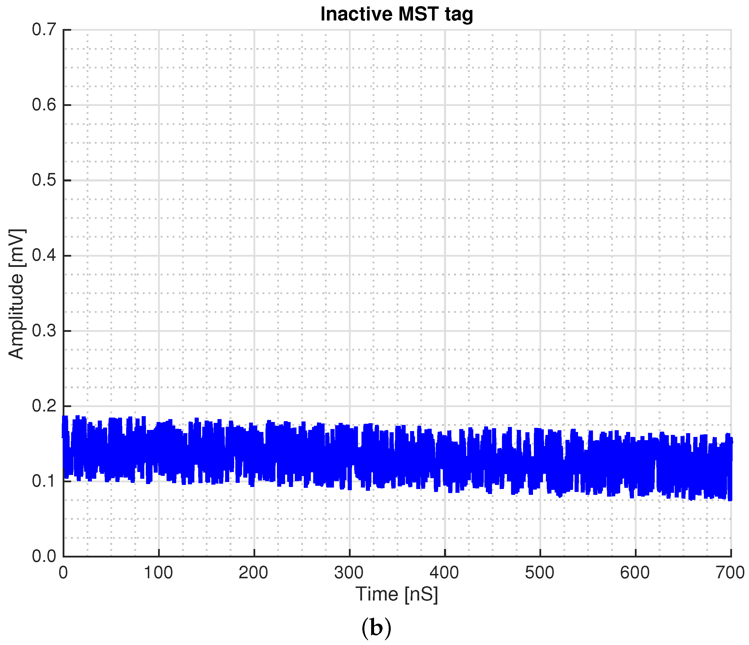
To illustrate the abilities of the MST method-based wireless sensors, the development of a wireless sensor tag is described in this section. To develop an MST sensor tag, the first step is to choose the electronic switch properly by considering the guidelines followed in [30]. MOSFET-based switches offer the best performances, which could lead to nearly the maximum theoretical upper limit for the . The MOSFET switch developed in Section III D of [30] was chosen for the considered MST tag prototypebecause it offers the best performances with respect to the communication range. The PIC18F876A microchip, a low-cost microcontroller, was chosen as the elaboration unit, to acquire, convert and send the proper modulation signal to the driven modulation circuit. This microcontroller is equipped with A/D channels to connect a different kind of sensor. Moreover, it is equipped with a low power wake-up module. To reduce the power consumption, the microprocessor is kept in stand-by mode, and it is activated by means of a suitable interrupt only to perform the measurement. A switching step down voltage regulator, the MAX1044 (Maxim company), was used to reduce the power consumption. The elaboration and the switching sub-units were assembled into a compact two-layer structure of dimensions mm. As can be seen from the photo in Figure 3, the prototype is quite compact. However, the dimensions could be further reduced since the elaboration unit was assembled with standard components and not with surface-mounted devices (SMD). To obtain a wireless temperature/humidity probe, the two A/D channels out of the four were connected to a precision temperature sensor LM35DZ and the humidity sensor HR202. The humidity and temperature sensors have been calibrated in a controlled environment. In particular, a climatic chamber (ANGELATONI DY1200 with a temperature and humidity range of C < T < 180 C and < H < ) was been kindly provided by the EMC company, Genoa Italy. Figure 4a,b reports the calibration graph for the temperature and humidity sensor, respectively. As can be observed from the graph of Figure 4, the agreement is quite good. The working of the MST tag is as follows: The microcontroller collects the data for the temperature and humidity from the sensors continuously and converts them into bits using the 12-bit AD converter. Then the data are transmitted by changing the loads of the tag antenna using the MOSFET switch. To transmit the data, the modulation frequency is considered as 2 kHz. Furthermore, the modulation protocol is the same as for the RFID systems in [32,33]. In detail, as a protocol, EM4102, and for the modulation, the Manchester modulation were used. In the Manchester modulation, a low to high transition is represented by a logical one state, and a high to low transition is represented by a logical zero state. The EM4102 protocol allows immediate integration with commercial and RFID systems, databases and other RFID resources. The data organized in the EM4102 are as follows: the first nine bits of the data represent a logical one state. These first nine bits signify the start of the data string as a marker sequence. Then, the remaining string is followed by 10 groups of four data bits and one even parity bit. Finally, four bits of a column parity (even) and a stop bit (zero) are used. The MST tag performs tasks like read, convert and transmit the string data and represents the measured temperature perfectly as long as it has power. Furthermore, the length of each bit in the tag is defined in terms of clock cycles. Any bit length can be used from 64, 32 to 16 clock cycles in the EM4102 protocol. For this preliminary experiment, a 32-bit length and a reference frequency clock of 100 kHz has been used. An example of data sequence, transmitted by the tag and measured at the reader, output with a digital storage oscilloscope (DSO) is reported in Figure 5a. The tag has been placed at an operative distance m from the reader. Figure 5b reports the reader output when the tag is not activated. As can be seen from the waveform reported in Figure 5a, the data are clearly detected. Concerning the measurement of the MST tag prototype’s power consumption, it was carried out using suitable checkpoints introduced in the driving circuit of the modulation and microcontroller section. The MST tag was tested under different realistic operative conditions. In particular, in standby, with the modulation driven circuit turned off, the microcontroller required 3 V and A; while during the measurement phase, the current required by the microcontroller was about A, considering that the modulation circuit required about mA. The total current required by the MST tag in normal working conditions was about A. The power supply was provided by two standard rechargeable (1.2 V, mA) batteries, which can ensure a measured lifetime of the MST tag of about 12 h of continuous operation.
The prototype was also equipped with a small solar panel ( and mA), able to guarantee not only the correct working conditions during the day, but also to recharge the two batteries, aimed at providing the necessary current during the night.
3.3. Experimental Setup and Measurement Campaign
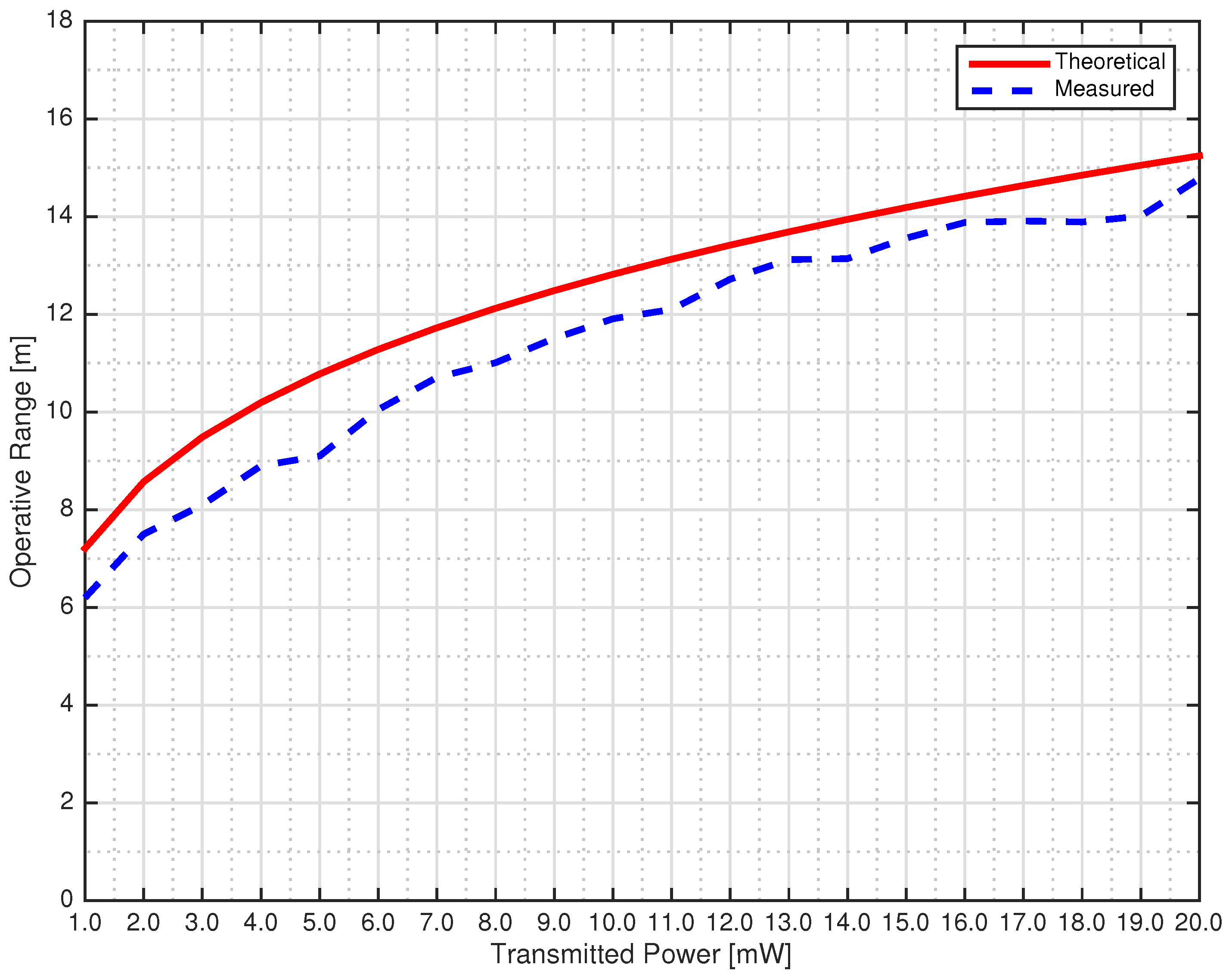
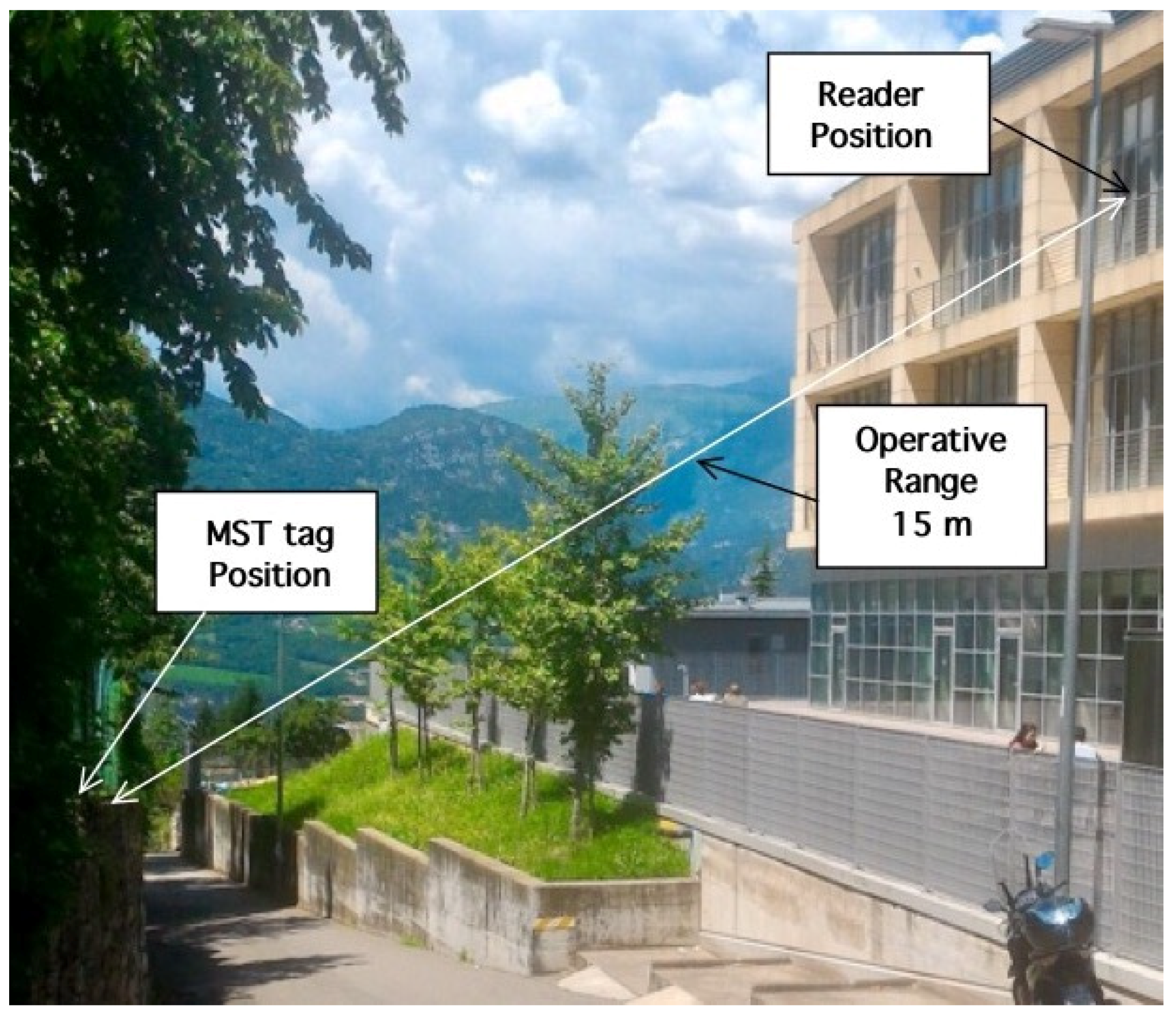
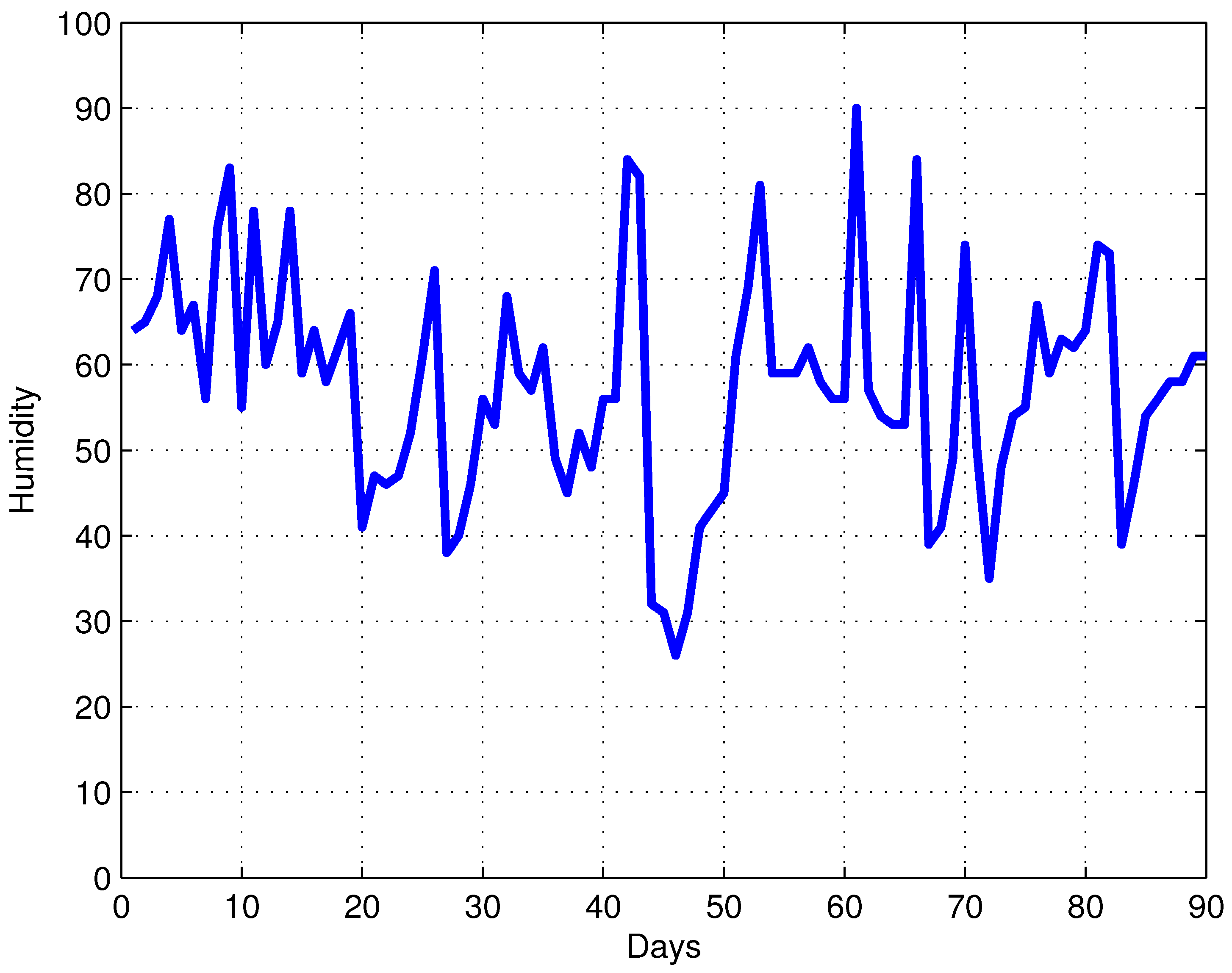
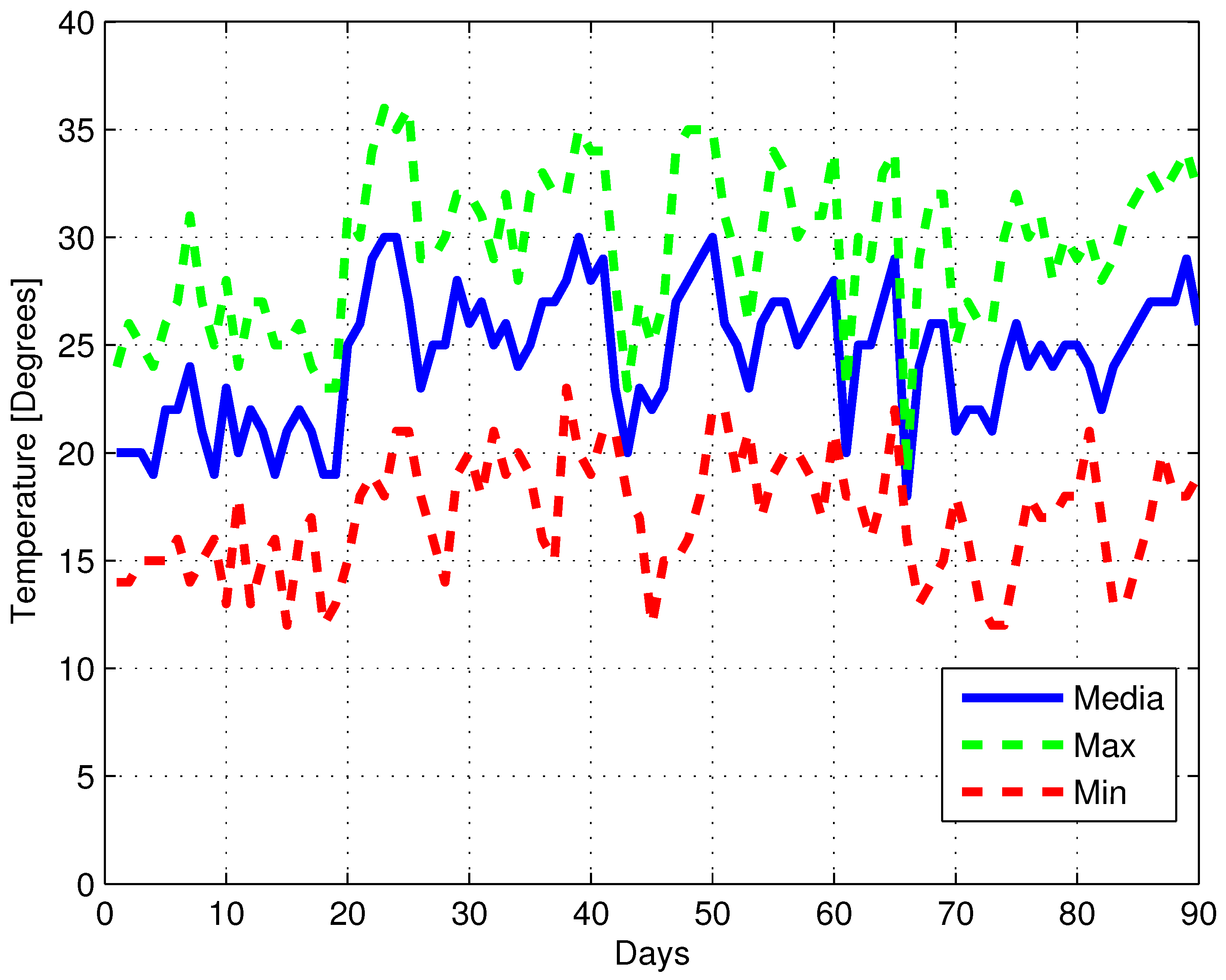
Before starting the measurement campaign, the theory described in Section 2 was assessed in a controlled environment. In particular, the operative range versus the transmitted power was measured. The operative range was considered valid when the transmitted tag sequence was correctly received a hundred times. Concerning the other system parameter dBi, dBi are the reader and tag antenna gains. respectively, and dBm is the minimum detectable power at the receiver, dBm. The obtained modulation efficiency was very close to the upper theoretical limit. For the the transmitter a direct digital synthesis (DDS) generator is able to modify its power in the range of 1 mW mW with a step of 1 mW. The results reported in Figure 6 show a good agreement between theoretical and experimental data. To assess the capabilities of the MST sensor, it was placed in a line of sight at a distance m from the reader. The data at the reader output were elaborated by means of a laptop provided with an A/D board, and a monitoring campaign of three months was carried out. In particular, the MST sensor was placed outdoors, exposed to the weather and used to monitor the temperature and humidity during the summer season. The photo of the considered measurement scenario is reported in Figure 7. The reader has been placed beyond a window of the laboratory, and the MST tag was placed on a small wall outside the building and exposed to meteorological phenomena. The distance between the reader and the tag was measured by using a commercial laser telemeter (the Bosh PLR40C with an accuracy of mm). The microcontroller was connected to the MST reader, and it was programmed to take a measurement every half an hour. In these operating conditions, the lifetime of the MST tag was more than 12 h. Figure 8 and Figure 9 show the humidity and temperature values recorded during the three-month campaign. As can be noticed from the data in Figure 8, the maximum and minimum temperature values recorded were and , respectively (typical temperature values of the summer in Northern Italy). These data were compared and confirmed by the official meteorological reports. This is a further demonstration of the MST-based systems’ potentialities as wireless sensors for real-time environmental monitoring applications. For the sake of comparison, the performances of other state of the art RFID systems [53,54,55] were compared with the proposed prototype. The data are reported in Table 1, and as can be noticed, the proposed MST system is able to reach a higher operative range with a lower transmitting power with respect to the other considered systems.
4. Conclusions
In this work, X band MST wireless sensors for an environmental system were designed, fabricated and tested. The MST system prototype was designed by a monostatic reader section, based on a high gain amplifier, a transmitting antenna, a homodyne detector and an elaboration unit based on a low-cost microcontroller. The MST probe used a rectangular patch antenna, loaded on two different loads by means of a MOSFET-based electronic switch. The system efficiency has been optimized, as well as the communication range r maximized. In particular, a distance of about m has been reached. The results of the experimental assessment demonstrated the effectiveness and potentialities of the proposed MST wireless sensor prototype and confirms that MST systems could be appealing alternatives to the standard wireless sensor. Future works will be devoted to the further miniaturization of the MST probe and the improvement of the communication range.
Author Contributions
M.D. proposed the idea, conceived and designed the experiments; M.M. performed the experiments and analyzed the data.
Funding
This research received no external funding
Acknowledgments
This work has been partially supported by the Italian Ministry of Foreign Affairs and the Italian Cooperation, Directorate General for Cultural and Economic Promotion and Innovation within the SNATCH Project (2017–2019).
Conflicts of Interest
The authors declare no conflict of interest.
References
- Doolin, D.M.; Sitar, N. Wireless sensors for wildfire monitoring. In Proceedings of the Smart Structures and Materials (NDE 2005), San Diego, CA, USA, 17 May 2005; pp. 6–105. [Google Scholar]
- Rad, M.; Shafai, L. A wireless embedded sensor for structural health monitoring applications. In Proceedings of the 13th Internationla Symposium Antenna Technology and Applied Electromagnetics Canadian Radio Science Meeting ANTEM/URSI, Toronto, ON, Canada, 15–18 February 2009; pp. 1–4. [Google Scholar]
- Polivka, M.; Svanda, M.; Hudec, P.; Zvanovec, S. UHF RF identification of people in indoor and open areas. IEEE Trans. Microw. Theory Tech. 2009, 57, 1341–1347. [Google Scholar] [CrossRef]
- Viani, F.; Oliveri, G.; Rocca, P.; Donelli, M.; Massa, A.; Lizzi, L. WSN-based solutions for security and surveillance. In Proceedings of the 3rd European Wireless Technology Conference, Paris, France, 27–28 September 2010; pp. 285–288. [Google Scholar]
- Cayirpurnar, O.; Tavli, B.; Kadioglu-Urtis, E.; Uludag, S. Optimal mobility patterns of multiple base stations wireless sensor network lifetime maximization. IEEE Sens. J. 2017, 17, 7177–7188. [Google Scholar] [CrossRef]
- Dobkin, D.M. The RF in RFID: Passive UHF RFID in Practice; Elsevier: New York, NY, USA, 2006. [Google Scholar]
- Finkenzeller, K. RFID Handbook, 2nd ed.; Wiley: New York, NY, USA, 2004. [Google Scholar]
- Rida, A.; Lakafosis, V.; Vyas, R.; Nikolaou, S.; Tentzeris, M. Review of technologies for low-cost integrated sensors. In Proceedings of the IEEE International Conference on RFID-Technologies and Applictions, Orlando, FL, USA, 12–14 April 2011. [Google Scholar]
- Capdevila, S.; Jofre, L.; Romeu, J.; Bolomey, J.C. Passive RFID based sensing. In Proceedings of the IEEE International Conference on RFID-Technologies and Applications, Orlando, FL, USA, 12–14 April 2011. [Google Scholar]
- Capdevila, S.; Jofre, L.; Romeu, J.; Bolomey, J.C. RFID multiprobe impedance based sensors. In IEEE Transaction Instrumentation and Measurement; IEEE: Piscataway, NJ, USA, 2010; Volume 59, pp. 3093–3101. [Google Scholar]
- Fuschini, F.; Piersanti, C.; Paolazzi, F.; Falciasecca, G. Analytical approach to the backscattering from UHF RFID transponder. IEEE Antennas Wirel. Propag. Lett. 2008, 7, 33–35. [Google Scholar] [CrossRef]
- Curty, J.P.; Joehl, N.; Dehollain, C.; Declercq, M.J. Remotely powered addressable UHF RFID integrated system. IEEE J. Solid-State Circuits 2005, 40, 2193–2201. [Google Scholar] [CrossRef]
- Girbau, D.; Ramos, A.; Lazaro, A.; Rima, S.; Villarino, R. Passive wireless temperature sensor based on time-coded UWB chipless RFID tags. IEEE Trans. Microw. Theory Tech. 2012, 60, 1–10. [Google Scholar] [CrossRef]
- Donelli, M. Design of long-range, powerless RFID sensor at 10 GHz. Electron. Lett. 2013, 49, 1277–1278. [Google Scholar] [CrossRef]
- Preradovic, S.; Menicanin, A. Chipless wireless sensor node. In Proceedings of the MIPRO, Opatija, Croatia, 21–25 May 2012; pp. 179–182. [Google Scholar]
- Donelli, M. A chipless RFID system based on substrate impedance waveguide resonators (SIW). In Proceedings of the 2017 IEEE-APS Topical Conference on Antennas and Propagation in Wireless Communications (APWC), Verona, Italy, 10–15 September 2017. [Google Scholar]
- Zhao, Z.; Tian, G.Y.; Zhang, J. IQ signal based RFID sensors for defect detection and characterization. Sens. Actuators A. Phys. 2018, 269, 14–21. [Google Scholar] [CrossRef]
- Yang, L.; Li, Y.; Lin, Q.; Jia, H.; Li, X.-Y.; Liu, Y. Tagbeat: Sensing Mechanical Vibration Period With COTS RFID Systems. IEEE/ACM Trans. Netw. 2017, 25, 3823–3835. [Google Scholar] [CrossRef]
- CHerrojo, R.; Mata-Contreras, J.; Núñez, A.; Paredes, F.; Ramon, E.; Martín, F. Near-Field Chipless-RFID System With High Data Capacity for Security and Authentication Applications. IEEE Trans. Microw. Theory Tech. 2017, 65, 5298–5308. [Google Scholar] [CrossRef] [Green Version]
- Garbati, M.; Perret, E.; Siragusa, R.; Halopè, C. Toward Chipless RFID Reading Systems Independent of Tag Orientation. IEEE Microw. Wirel. Compon. Lett. 2017, 27, 1158–1160. [Google Scholar] [CrossRef]
- Grebien, S.; Kulmer, J.; Galler, F.; Goller, M.; Leitinger, E.; Arthaber, H.; Witrisal, K. Range Estimation and Performance Limits for UHF-RFID Backscatter Channels. IEEE J. Radio Freq. Identif. 2017, 1, 39–50. [Google Scholar] [CrossRef]
- Qin, H.; Peng, Y.; Zhang, W. Vehicles on RFID: Error-Cognitive Vehicle Localization in GPS-Less Environments. IEEE Trans. Veh. Technol. 2017, 66, 9943–9957. [Google Scholar] [CrossRef]
- Li, H.; Zhu, J.; Yu, Y. Compact Single-Layer RFID Tag Antenna Tolerant to Background Materials. IEEE Access 2017, 5, 21070–21079. [Google Scholar] [CrossRef]
- Chuang, P.-J.; Tsai, W.-T. SwitchTable: An efficient anti-collision algorithm for RFID networks. IET Commun. 2017, 11, 2221–2227. [Google Scholar] [CrossRef]
- Zhang, J.; Shen, Z. Compact and High-Gain UHF/UWB RFID Reader Antenna. IEEE Trans. Antennas Propag. 2017, 65, 5002–5010. [Google Scholar] [CrossRef]
- Bolomey, J.C.; Capdevila, S.; Jofre, L.; Romeu, J. Electromagnetic modeling of RFID-modulated scattering mechanism. Application to tag performance evaluation. Proc. IEEE 2010, 11, 1555–1569. [Google Scholar] [CrossRef]
- Bolomey, J.C.; Gardiol, G. Engineering Applications of the Modulated Scattering Technique; House, A., Ed.; Arthec House: London, UK, 2001. [Google Scholar]
- Bracht, R.; Miller, E.K.; Kuckertz, T. An impedance modulated reflector system. IEEE Potentials 1999, 18, 29–33. [Google Scholar] [CrossRef]
- Harrington, R. Electromagnetic scattering by antennas. IEEE Trans. Antennas Propag. 1963, 5, 595–596. [Google Scholar] [CrossRef]
- Donelli, M. Guidelines for the design and optimization of wireless sensors based on the modulated scattering techniques. IEEE Trans. Instrum. Meas. 2014, 63, 1824–1833. [Google Scholar] [CrossRef]
- Fletcher, R.; Marti, J.P.; Redemske, R. Study of UHF RFID signal propagation through complex media. In Proceedings of the 2005 IEEE Antennas and Propagation Society International Symposium, Washington, DC, USA, 3–8 July 2005; pp. 747–750. [Google Scholar]
- Kim, D.Y.; Yook, J.G.; Yoon, H.G.; Jang, J. Interference analysis of UHF RFID systems. Prog. Electromag. Res. B 2008, 4, 115–126. [Google Scholar] [CrossRef]
- Leong, S.; Ng, J.M.L.; Kole, H. The reader collision problem in RFID systems. In Proceedings of the 2005 IEEE International Symposium on Microwave, Antenna, Propagation and EMC Technologies for Wireless Communication, Beijing, China, 8–12 August 2005; pp. 747–750. [Google Scholar]
- Picquenard, A. Radiowave Propagation; MacMillan: Bath, UK, 1974. [Google Scholar]
- Ostradahimi, M.; Mojabi, P.; Noghanian, S.; Shafai, L.; Pistorius, S.; Lovetri, J. A novel tomography system based on the scattering probe technique. IEEE Trans. Instrum. Meas. 2012, 62, 379–390. [Google Scholar] [CrossRef]
- Donelli, M.; Pastorino, M.; Caorsi, S. A passive antenna system for data acquisition in scattering applications. IEEE Antennas Wirel. Propag. Lett. 2001, 1, 203–206. [Google Scholar]
- Abou-Khousa, M.A.; Zoughi, R. Multiple loaded scatterer method for E-field mapping applications. IEEE Trans. Antennas Propag. 2010, 58, 900–907. [Google Scholar] [CrossRef]
- Bracht, R.; Miller, E.K.; Kuckertz, T. Using an impedance-modulated reflector for passive communication. In Proceedings of the IEEE Antennas Propagation International Symposium, Montreal, QC, Canada, 13–18 July 1997; pp. 1070–1073. [Google Scholar]
- Tehran, H.M.; Laurin, J.; Kashyap, R. Optically modulated probe for precision near-field measurements. IEEE Trans. Instrum. Meas. 2010, 59, 2755–2762. [Google Scholar] [CrossRef]
- Vauchamp, S.; Lalande, M.; Andrieu, J.; Jecko, B.; Lasserre, J.L.; Pècastain, L.; Cadilhon, B. Utilization of target scattering to measure high-level electromagnetic field: The Michelson method. IEEE Trans. Instrum. Meas. 2010, 59, 2405–2413. [Google Scholar] [CrossRef]
- Choi, J.H.; Moon, J.I.; Park, S.O. Measurement of the modulated scattering microwave fields using dual-phase lock-in amplifier. IEEE Antennas Wirel. Propag. Lett. 2004, 3, 340–343. [Google Scholar] [CrossRef]
- Liang, W.; Hygate, G.; Nye, J.F.; Gentle, D.G.; Cook, R.J. A probe for making near-field measurements with minimal disturbance: The optically modulated scatterer. IEEE Trans. Antennas Propag. 1997, 1, 772–780. [Google Scholar] [CrossRef]
- Bolomey, J.C.; Capdevila, S.; Jofre, L.; Tedjini, S. Sensitivity analysis for wireless dielectric reflectometry with modulated scatterers. In Proceedings of the 15th URSI General Assembly and Scientific Symposium, Istanbul, Turkey, 13–20 August 2011; pp. 1–4. [Google Scholar]
- Donelli, M.; Viani, F. Remote inspection of the structural integrity of engineering structures and materials with passive MST probes. IEEE Trans. on Geosci. Remote Sens. 2017, 55, 12. [Google Scholar] [CrossRef]
- Donelli, M. A broadband modulated scattering technique (MST) probe based on a self-complementary antenna. In Proceedings of the 2017 IEEE-APS Topical Conference on Antennas and Propagation in Wireless Communications (APWC), Verona, Italy, 10–15 September 2017. [Google Scholar]
- Donelli, M.; Viani, F. Graphene based antenna for the design of modulated scattering technique (MST) wireless sensors. IEEE Antennas Wirel. Propag. Lett. 2016, 15, 1561–1564. [Google Scholar] [CrossRef]
- Donelli, M. A 24 GHz environmental sensor based on the modulated scattering technique (MST). In Proceedings of the IEEE Conference on Antenna Measurements and Applications CAMA 2014, Juan Les Pens, France, 16–19 November 2014. [Google Scholar]
- Donelli, M.; Franceschini, D. Experiments with a modulated scattering system for through-wall identification. IEEE Antennas Wirel. Propag. Lett. 2010, 9, 20–23. [Google Scholar] [CrossRef]
- Vena, A.; Perret, E.; Tedijini, S. Chipless RFID Based on RF Encoding Particle; Elsevier: Exeter, UK, 2016. [Google Scholar]
- Vernon, F. Application of the microwave homodyne. IEEE Trans. Antennas Propagat. 1952, PGAP-4, 110–116. [Google Scholar] [CrossRef]
- King, R.J. Microwave Homodyne Systems; P. Peregrinus on behalf of the Institution of Electrical Engineers: London, UK, 1978. [Google Scholar]
- Skolnik, M.I. Radar Handbook; McGraw-Hill: New York, NY, USA, 1990. [Google Scholar]
- Kharthaus, U.; Fisher, M. Fully integrated passive UHF-RFID transponder IC with 16.7 nW minimun RF power. IEEE J. Solid State Circuits 2003, 38, 1602–1608. [Google Scholar] [CrossRef]
- Kitayoshi, H.; Sawaya, K. Long range passive RFID-Tag for sensor networks. IEEE Veh. Tech. Conf. 2005, 4, 2696–2700. [Google Scholar]
- Scholl, G.; Horen, C.; Riha, E.; Ruppel, C.W.; Walff, U.; Riha, G.; Weigel, R. SAW based radio sensor system. IEEE Microw. Mag. 2006, 4, 69–76. [Google Scholar]
Figure 1.
Schematic of a mono-static modulated scattering technique (MST)-based measurement system.

Figure 2.
Photograph of the compact MST reader.

Figure 3.
Photo of the MST tag equipped with temperature and humidity probes and a solar panel.

Figure 4.
Temperature and humidity calibration curves obtained with a climatic chamber: (a) temperature and (b) humidity.
Figure 4.
Temperature and humidity calibration curves obtained with a climatic chamber: (a) temperature and (b) humidity.


Figure 5.
Example of the data structure received at the reader output (a). Signal detected with an inactive tag (b).
Figure 5.
Example of the data structure received at the reader output (a). Signal detected with an inactive tag (b).


Figure 6.
Operative range vs. transmitted power. Continuous red line, theoretical; dotted blue line, experimental.
Figure 6.
Operative range vs. transmitted power. Continuous red line, theoretical; dotted blue line, experimental.

Figure 7.
Photo of the experimental setup.

Figure 8.
Three-month humidity measurement campaign data.

Figure 9.
Three-month temperature measurement campaign data.


© 2018 by the authors. Licensee MDPI, Basel, Switzerland. This article is an open access article distributed under the terms and conditions of the Creative Commons Attribution (CC BY) license (http://creativecommons.org/licenses/by/4.0/).
Share and Cite
MDPI and ACS Style
Donelli, M.; Manekiya, M. Development of Environmental Long Range RFID Sensors Based on the Modulated Scattering Technique. Electronics 2018, 7, 106. https://doi.org/10.3390/electronics7070106
AMA Style
Donelli M, Manekiya M. Development of Environmental Long Range RFID Sensors Based on the Modulated Scattering Technique. Electronics. 2018; 7(7):106. https://doi.org/10.3390/electronics7070106
Chicago/Turabian StyleDonelli, Massimo, and Mohammedhusen Manekiya. 2018. "Development of Environmental Long Range RFID Sensors Based on the Modulated Scattering Technique" Electronics 7, no. 7: 106. https://doi.org/10.3390/electronics7070106
Note that from the first issue of 2016, this journal uses article numbers instead of page numbers. See further details here.