Novel Neural Control of Single-Phase Grid-Tied Multilevel Inverters for Better Harmonics Reduction

1
Department of Electrical Engineering and Computer Science, Texas A&M University-Kingsville, Kingsville, TX 78363, USA
2
Department of Electrical and Computer Engineering, The University of Alabama, Tuscaloosa, AL 35401, USA
*
Author to whom correspondence should be addressed.
Electronics 2018, 7(7), 111; https://doi.org/10.3390/electronics7070111
Submission received: 11 June 2018
/
Revised: 2 July 2018
/
Accepted: 10 July 2018
/
Published: 12 July 2018
(This article belongs to the Special Issue Power Quality in Smart Grids)
Abstract
:A single-phase Cascaded H-Bridge (CHB) grid-tied multilevel inverter is introduced with a detailed discussion of the proposed novel neural controller for better efficiency and power quality in the integration of renewable sources. An LCL (inductor-capacitor-inductor) filter is used in the multilevel inverter system to achieve better harmonic attenuation. The proposed Neural Network (NN) controller performs the inner current control and tracks the references generated from the outer loop to satisfy the requirements of voltage or power control. Two multicarrier-based Pulse Width Modulation (PWM) techniques (phase-shifted modulation and level-shifted modulation) are adopted in the development of the simulation model to drive the multilevel inverter system for the evaluation of the neural control technique. Simulations are carried out to demonstrate the effectiveness and efficient outcomes of the proposed neural network controller for grid-tied multilevel inverters. The advantages of the proposed neural control include a faster response speed and fewer oscillations compared with the conventional Proportional Integral (PI) controller based vector control strategy. In particular, the neural network control technique provides better harmonics reduction ability.
1. Introduction
The distributed power generation system [1,2] has proven to be a very useful way of using renewable sources in small and large-scale energy production. Grid-tied inverters are widely used in renewable energy integration, e.g., solar power, fuel cell, and wind energy. With the increasing interest in renewable energy generation system, the demand for high power integration to the grid from these renewable energy sources increases. However, the voltage ratings of the currently available power electronic devices are still not sufficient for medium and high voltage grid applications. For example, a 6.5 kV rated device is currently available in the market while the 10 kV rated SiC IGBT and MOSFET are still under development of the research facilities [3]. Hence, the conventional two-level design of the converter is not feasible for medium to high voltage applications.
Multilevel converters have been shown to be a very promising and reliable solution to connect medium/high voltage level distribution grids by eliminating the transformer and reducing the system’s cost. Moreover, the high switching frequency feature helps to reduce the harmonic content of the inverter waveform. The converter power ratings can be increased by adding the number of output levels without increasing the power or voltage ratings of the switching devices which is not possible with conventional two-level topology due to the voltage and current limitation of each individual power device. Furthermore, as the multilevel converters generally offer lower Total Harmonic Distortion (THD), multilevel converters have been gaining more interest in regard to their use in single-phase grid-tied photovoltaic systems for power conversion [4,5].
There are many different topologies designed for multilevel converters depending on the specifications and the applications [6,7,8]. Because of their large power density and high reliability, the most popular multilevel converters for the industries are the Cascaded H-Bridge (CHB) voltage source converters, Neutral Point Clamped, Flying Capacitor Converters, and Modular Multilevel Converters. As multilevel converters generally consist of more switching devices and more numbers of gate-drivers than those for the conventional converters, their modulation technique is more complicated than that for conventional converters. According to how the carrier signals are formed, there are two types of sinusoidal modulation methods: phase-shifted modulation and level-shifted modulation. Further, the level-shifted modulation has three types: phase disposition, phase opposition disposition, and alternate phase opposition disposition [9].
Recently, lots of researchers have tried to implement dynamic programming (DP) [10] for the optimal control of nonlinear systems [11]. As one type of Approximate Dynamic Programming (ADP) methods, Adaptive Critic Designs (ACD) have been adopted to approximate the optimal cost and optimal control of a system [12,13]. In [14,15], a neural network (NN) was trained based on the Approximate Dynamic Programming principle to control a three-phase L filter-based Grid-Connected Converter (GCC) system. The ADP-based NN controlling of the LCL filter-based three-phase [16] and single-phase [17] GCC systems was also demonstrated to be able to yield an excellent performance compared to the conventional PI controller based control methods. In [16], it has been demonstrated that Recurrent Neural Network (RNN) vector control has a wider stability region for the system parameter change than Active Damping (AD) or Passive Damping (PD) vector control for LCL-based grid-connected converter systems.
This research work intends to propose a novel neural network control strategy for a single phase five-level Cascaded H-Bridge (CHB), grid-tied inverter to allow better quality grid integration of renewable sources. The specific contributions of the paper are listed as follows: (1) an approach to utilize the neural network controller for the single-phase, grid-tied, Cascaded H-Bridge, multilevel converters, (2) a method to train the NN controller directly in a closed-loop control process by the Levenberg–Marquardt (LM) algorithm combining with a novel Forward Accumulation Through Time (FATT) algorithm, and (3) investigation and comparison of the proposed NN controller with the conventional PI-based vector controller under both phase-shifted and level-shifted modulations.
The rest of the paper is structured as follows. The grid-tied inverter design and multilevel converter structure are discussed in Section 2. The decoupled PI-based d-q vector control structure and modulation technique are described in Section 3. The novel neural control is detailed in Section 4. A complete discussion on the simulation model and results are presented in Section 5. Section 6 summarizes the complete research work.
2. Single-Phase Grid-Tied Multilevel Inverters
Grid-Tied Multilevel Inverter
The schematic diagram of a grid-tied multilevel inverter is shown in Figure 1. In order to keep the harmonics as low as possible, an LCL filter is placed between the inverter and the grid.
A cascaded H-bridge (CHB) voltage source converter was adopted to design the grid-tied multilevel converter. Two identical H-bridge converters are connected in series to generate five-level voltage waveforms. Figure 2 shows the schematic diagram of the single-phase five level cascaded H-bridge (CHB) converter, in which the two legs of the upper bridge are denoted as Leg 1 and Leg 2, and the two legs of the lower bridge are denoted as Leg 3 and Leg 4. and represent the DC voltages across two capacitors, respectively. stands for the combined CHB DC voltage.
In general, for a number (N) of series-connected H-bridge modules, (2N + 1) number of output voltage levels will be generated. One individual module of the H-bridge converter generates three different voltage outputs: , 0, and . When two H-bridge modules are connected in series, the combination of those two modules gives output voltages on five levels, which are , , 0, , and .
3. Control Strategy and Modulation Technique
3.1. Imaginary Circuit
For a single-phase grid-tied inverter, an imaginary circuit is needed to create another phase for the implementation of the d-q vector control. The created imaginary circuits have the same amplitude as the real circuits with phase shift in all quantities. The real circuit and imaginary circuit together constitute the - frame of the LCL system. The system equations in the - frame can be further transferred into the d-q domain by a transformation matrix, T, as shown in Equation (1) [18]:
Also, the inverse transformation matrix from the d-q frame to the - frame is just inverse of matrix T [18].
3.2. Mathematical Model
Using the current direction defined in Figure 1, the system Equation (2) of the real circuit describes the system equations of the single-phase LCL filter based grid-tied inverter system,
where and stand for the resistance and inductance of the grid-side inductor; and represent the resistance and inductance of the converter-side inductor; C and specify the parallel capacitor and the capacitor voltage; and , , , and define the grid voltage, the converter voltage, the grid current, and the converter-side current, respectively.
The equations described in Equation (2) correspond to the -axis quantities. Accordingly, the Equation (3) describing the imaginary circut are built into the -axis domain:
where, , , , , and stand for those corresponding real circuit quantities in the imaginary circuit, respectively. Specifically, = vge/2, = vce/2, = vcve/2, = ige/2, and = icce/2.
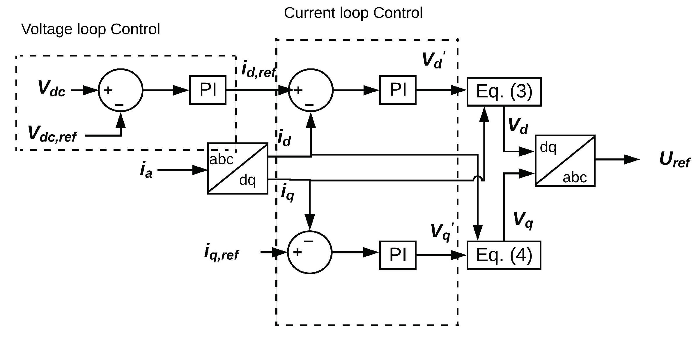
3.3. PI-Based Vector Control
For an LCL filter-based grid-tied inverter system, one simple method is to omit the parallel capacitance, and thus the LCL filter will be simplified into the L filter [19].
By omitting the capacitance impact and using the - frame, Equations (2) and (3) of the single-phase LCL grid-tied inverter system are simplified in Equation (4):
Further, applying the transformation matrix T to Equation (4) gives the Equation (5) in the d-q frame for the design of the current loop controllers:
The tuning of PI controllers is based on and in Equation (5) for the d- and q-axis control loops with all the other terms considered to be the compensation items. The corresponding relationships between the - domain and the d-q domain are listed as follows: , ↔ , , , ↔ , , and , ↔ , .
However, this simplification utilizes an imprecise description of the system and could cause potential oscillatory and/or unstable dynamic behavior. To overcome this problem, the LCL filter or the designed controller needs to be properly damped [20,21].
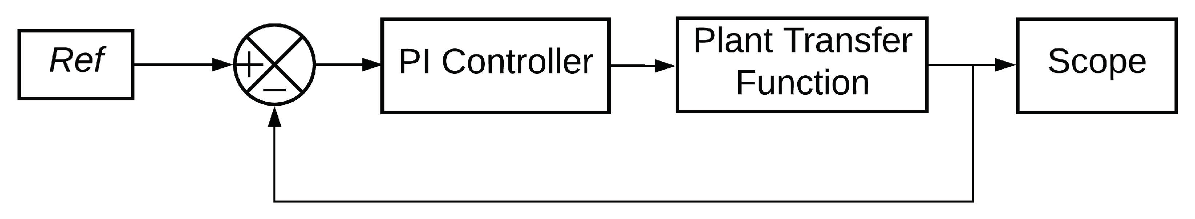
The PI controller for current loop control is tuned by the plant transfer function, . Figure 3 demonstrates the tuning processing of the current-loop PI controllers.
The control structure for the closed-loop model is shown in Figure 4.
To tune the PI controller, the phase margin was selected as 60 deg with the bandwidth set as 1500 rad/s. This selection tended to generate the best results considering the Pulse Width Modulation (PWM) saturation constraints in our tests. In order to solve the resonance phenomenon associated with the LCL filter, an active damping method was adopted in this paper [22] as such methods do not consume extra power like passive damping methods. A low-pass filter was added to the output of the current-loop controllers [23] at the resonance frequency, as shown in Equation (6) [24]:
The outer DC-link voltage control loop was designed based on the principle of power balance [25] and the tuning process for the outer voltage controller had the similar process as that for the current-loop controllers.
3.4. Modulation Technique
Different modulation techniques are compatible for different converter topologies. PWM exhibits one of the most promising for multilevel converters by also applying some changes in carrier generation. Multilevel converters require a multicarrier technique for the PWM method since these converters have more legs than conventional two-level converters.
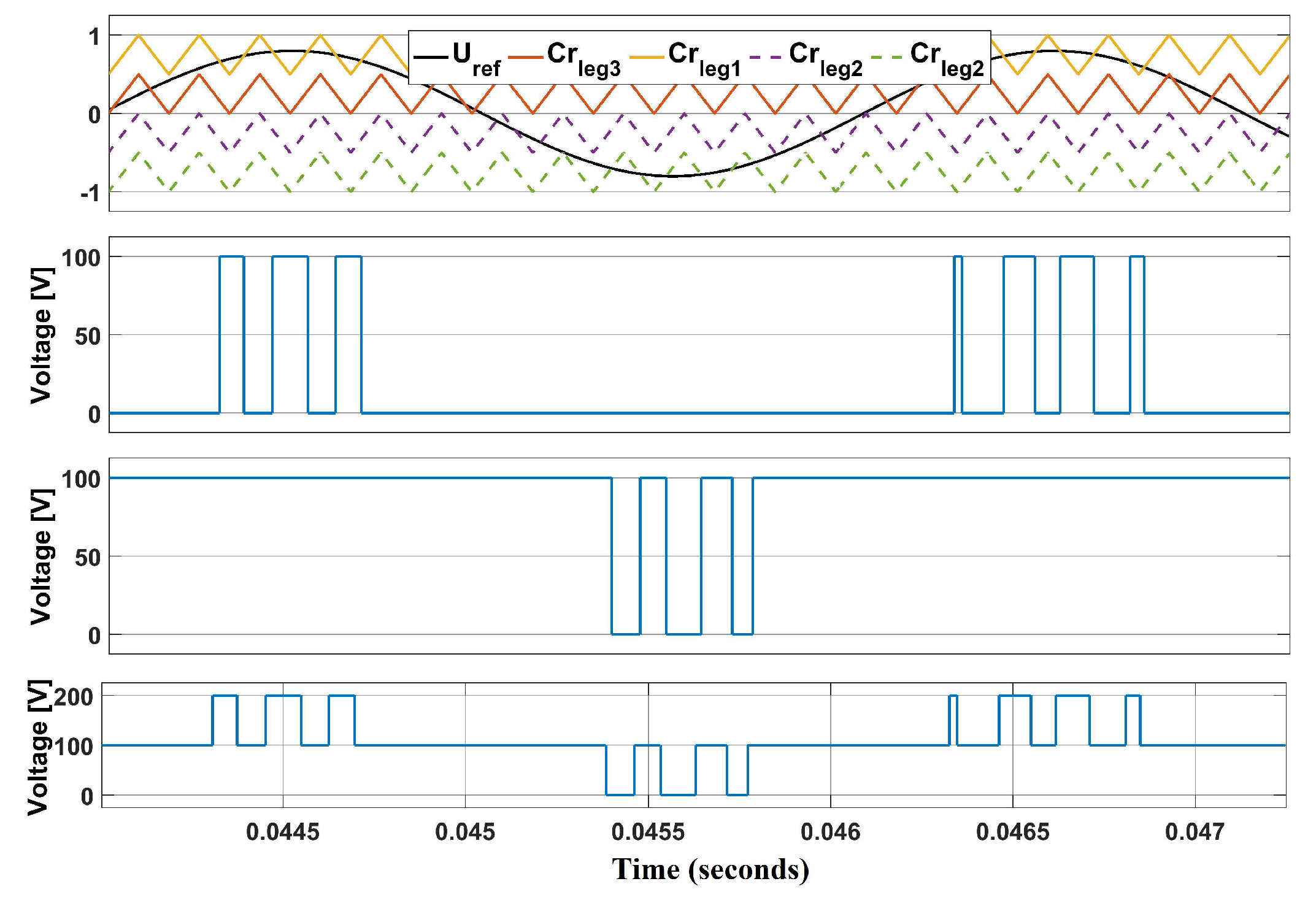
For phase-shifted modulation, a CHB multilevel converter containing N cells will need a carrier phase shift of [26]. For five-level converters, the total number of cell required is 2, which indicates that a phase shift of = is required for phase shifting carrier signal modulation. Carrier signals are shifted from one bridge to another. Figure 5 demonstrate the phase shift modulation technique where , , , and represent the carrier signals for H-Bridge 1 and H-Bridge 2.
Since the carrier signals are shifted in level during level-shifted modulation, the number of levels is calculated based on the number of output steps. For instance, the m level CHB converter requires () number of the carrier signals. In this case, () = 4 carriers are required. The uppermost and lowest carrier signals, which are indicated as and , and the inner carrier signals, which are indicated as and in Figure 6, were used to generate the PWM for H-Bridge 1 and H-Bridge 2, respectively.
4. Novel Neural Control Technique
4.1. Current-Loop Neural Network Controller
In contrast to using the NN for classification [27] and forecasting [28], the NN was adopted as the controller directly in the closed-loop inverter control systems in this paper. The proposed NN controller has an input preprocessing block and a feed-forward network as shown in Figure 7.
To avoid input saturation, the input preprocessing block regulates the inputs into the range [−1, 1]. The outputs of the input preprocessing block are and , in which is the error term and is defined as = − , and is the integral of the error terms and is defined as . The integral terms are numerically calculated by the trapezoid formula . When , ≡ .
As shown in Figure 7, the feed-forward NN has two hidden layers with six nodes in each hidden layer. The NN outputs two d-q voltage control signals, . The hyperbolic tangent functions (tanh) are adopted as activation functions for all neurons. A two-hidden-layer NN generally yields a stronger approximation ability [29] than a one-hidden-layer NN, and the training of a two-hidden-layer network is relatively easier than that for a network with three or even more hidden layers. The number of neurons in each hidden layer was selected by a trial-and-error method [16].
4.2. Training Neural Network Controller
The principle of Bellman’s optimality is widely employed [10] in Dynamic Programming (DP) and is a useful method for solving optimal control problems [12].
The DP cost function for the NN training is defined as
in which, is a discount factor, and the range of is 0 < ≤ 1. is often called the utility or local cost function. The DP cost function, , is referred to as the cost-to-go of initial state, , in which j > 0. The goal of the NN training is to minimize the DP cost, , in Equation (8).
To train a moderate number of network parameters, the Levenberg–Marquardt (LM) algorithm appears to be the fastest convergence algorithm [31], and usually, can achieve better convergence results compared with the backpropagation through time (BPTT) algorithm especially for an RNN [32].
However, in order to utilize the LM algorithm, the cost function, , in Equation (8) has to be expressed in a sum-of-squares format. When , and for a limited number of sequences, the cost function, , can be rewritten as Equation (9) through a simple transformation: .
and the gradient can be expressed in a matrix product form:
where the Jacobian matrix is
Equation (12) gives the weightupdate formula [31,33,34] for training a neural network (NN) controller :
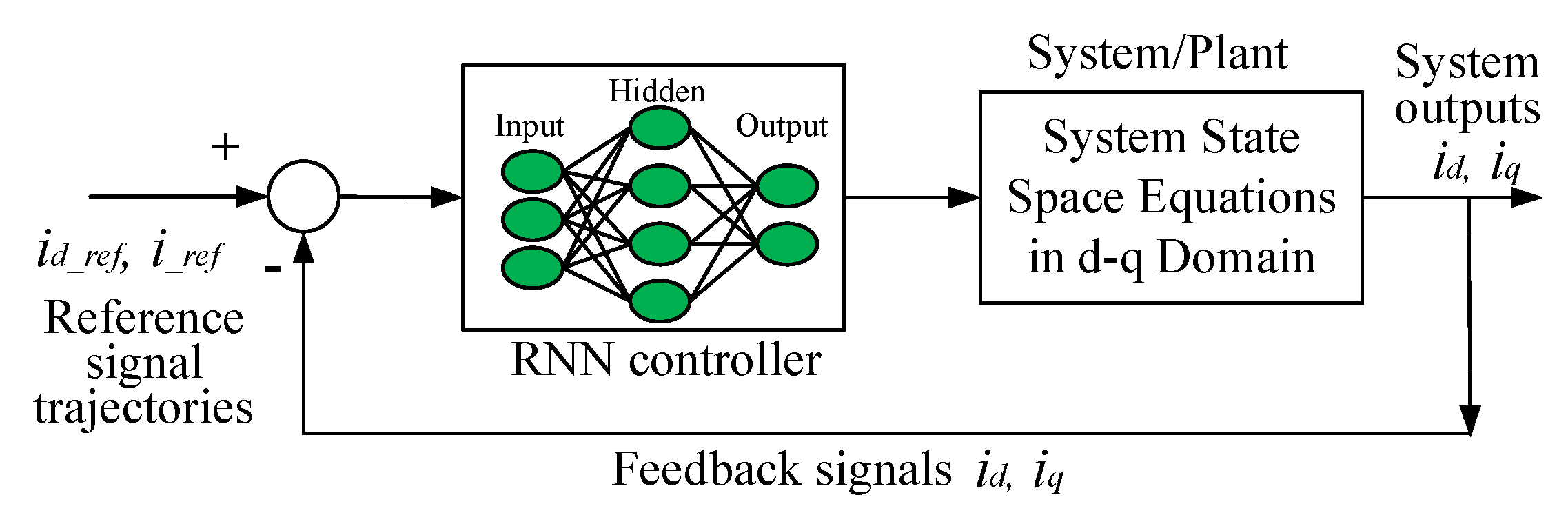
In a closed-loop control environment, the NN will be a Recurrent Neural Network as the outputs of a CHB system are fed back to the NN as the inputs at the next time step, as illustrated in Figure 8. The system state-space equations in the d-q domain serve as the feedback confections for the NN controller.
Further, Equation (13) describes the system equation of an LCL filter-based GCC in the d-q domain [35], which was used for NN training, as shown in Figure 7, Figure 8 and Figure 9.
where is the angular frequency of the grid voltage, and all other symbols are consistent with those used in Equations (2) and (3). The corresponding relationships of all the variables between the d-q domain and the single-phase circuit domain are the following: , ↔ ,, , ↔ ,, , ↔ ,, , ↔ ,, and , ↔ ,.
5. Simulation Results
MATLAB SIMULINK was used for design verification and comparison in this paper. Figure 10 shows the Simulink model for the grid-tied CHB inverter. Both the proposed novel RNN control and conventional PI-based vector control were implemented in the shown Simulink model. Two modulation techniques, that is phase-shifted modulation and model-shifted modulation, were adopted in the simulation.
Table 1 specifies the parameters of a single-phase CHB grid-tied inverter system. Most system parameters were taken from references [36,37]; the LCL filter values were selected to provide better attenuation results.
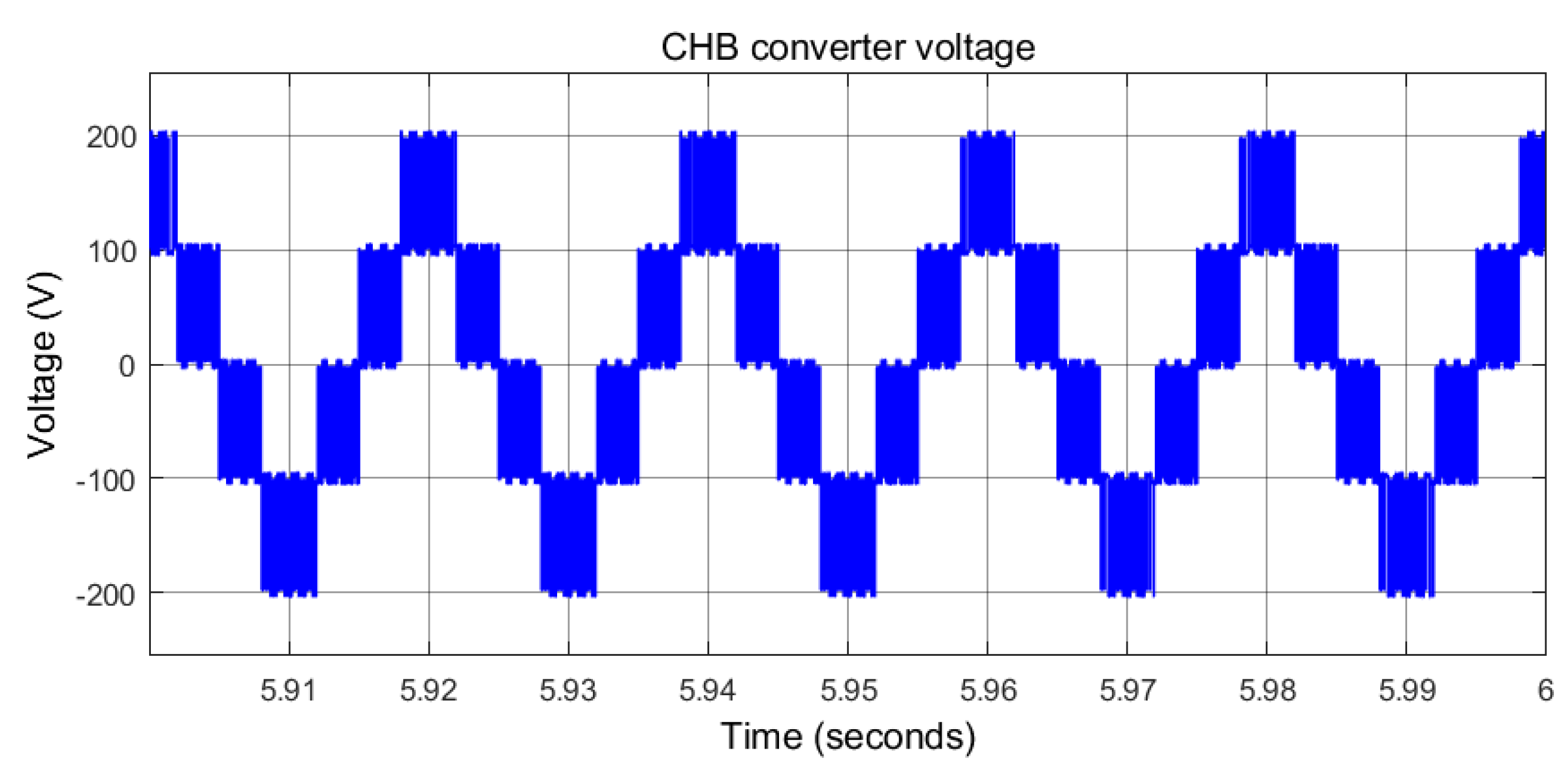
5.1. Five-Level CHB DC Voltage
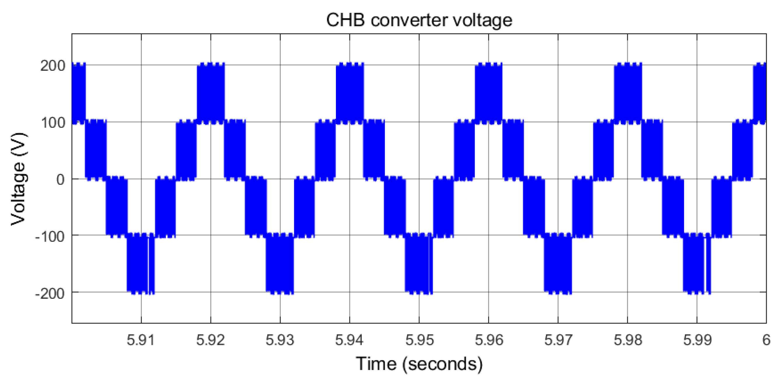
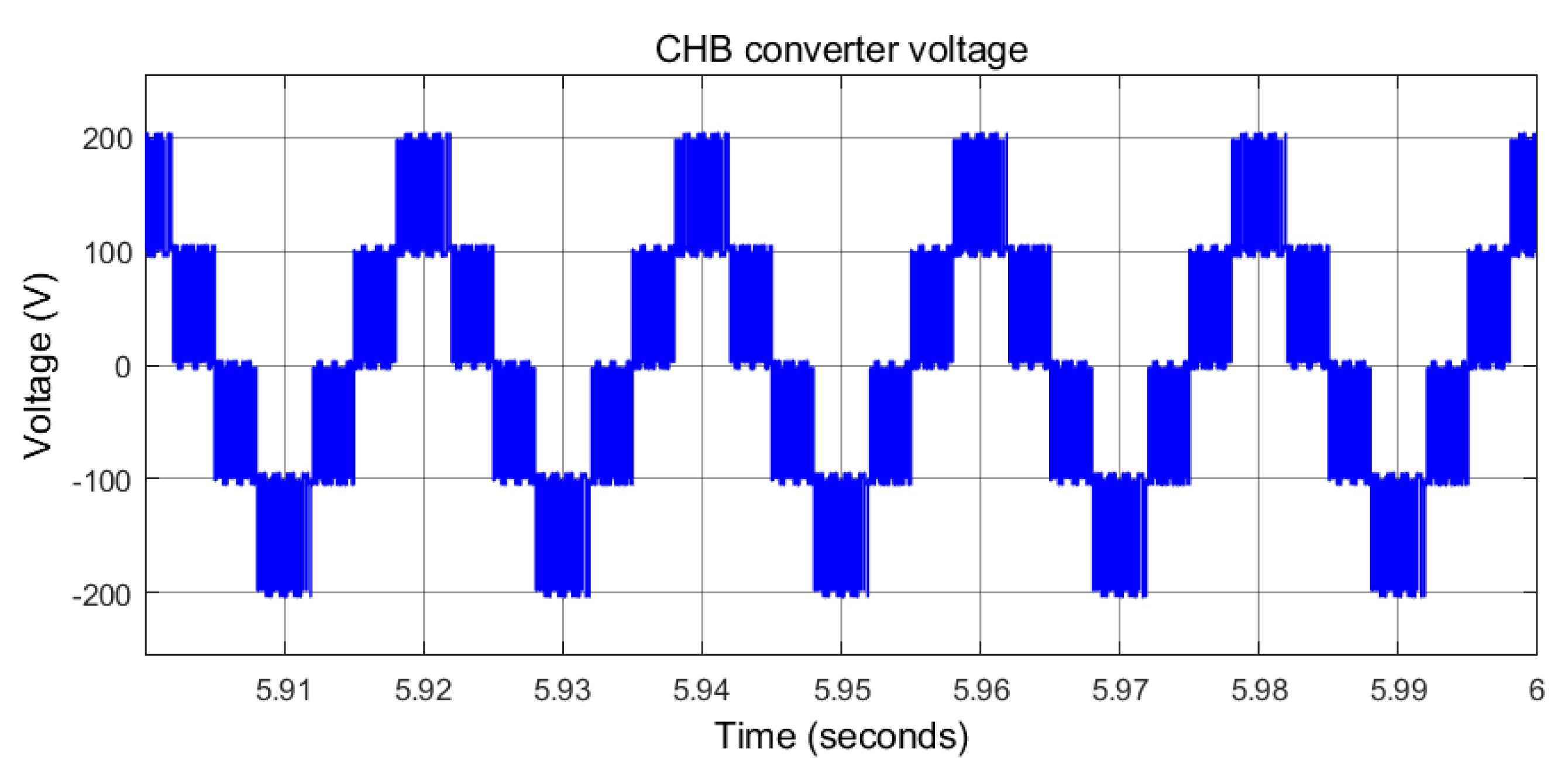
Two cascaded-connected H-Bridge converters generate combined five-level converter voltages. Figure 11 and Figure 12 show the generated five-level CHB converter voltages under conventional PI-based vector control with phase-shifted modulation and level-shifted modulations, respectively. Figure 13 and Figure 14 shows the generated five-level CHB converter voltages under novel RNN control with phase-shifted modulation and level-shifted modulations, respectively.
Compared with one H-Bridge-based grid-tied inverter, the five-level converter systems can generate more close to sinusoidal voltage waveform and less Total Harmonic Distortion (THD). This advantage will definitely help better and high-quality integration of renewable sources to be obtained.
5.2. Voltage Tracking
Figure 15 and Figure 16 show the CHB combined DC voltage, the voltage, , of capacitor , and the voltage, , of capacitor under conventional PI-based vector control with phase-shifted modulation and level-shifted modulations, respectively.
Figure 17 and Figure 18 show the CHB-combined DC voltage, the voltage, , of capacitor , and the voltage, of capacitor under novel RNN control with phase-shifted modulation and level-shifted modulations, respectively.
Exactly the same voltage loop PI controllers were used in all simulations. The CHB combined DC voltages in four scenario simulations were all able to stabilize at 200 V, as expected.
5.3. Current Tracking in the d-q Domain
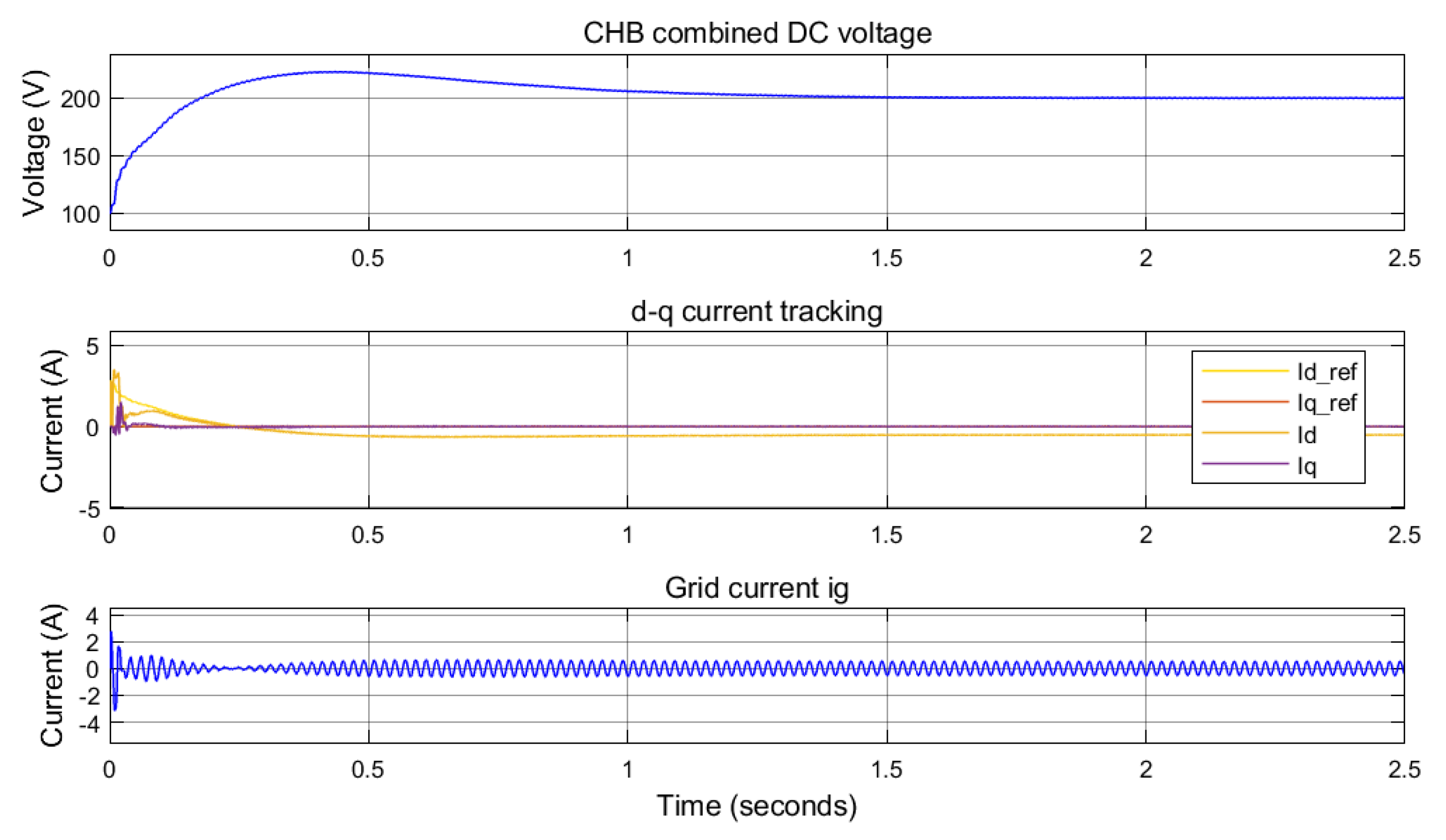
Figure 19 and Figure 20 show the CHB-combined DC voltage, d-q current tracking and the grid current, , under conventional PI-based vector control with phase-shifted modulation and level-shifted modulations, respectively.
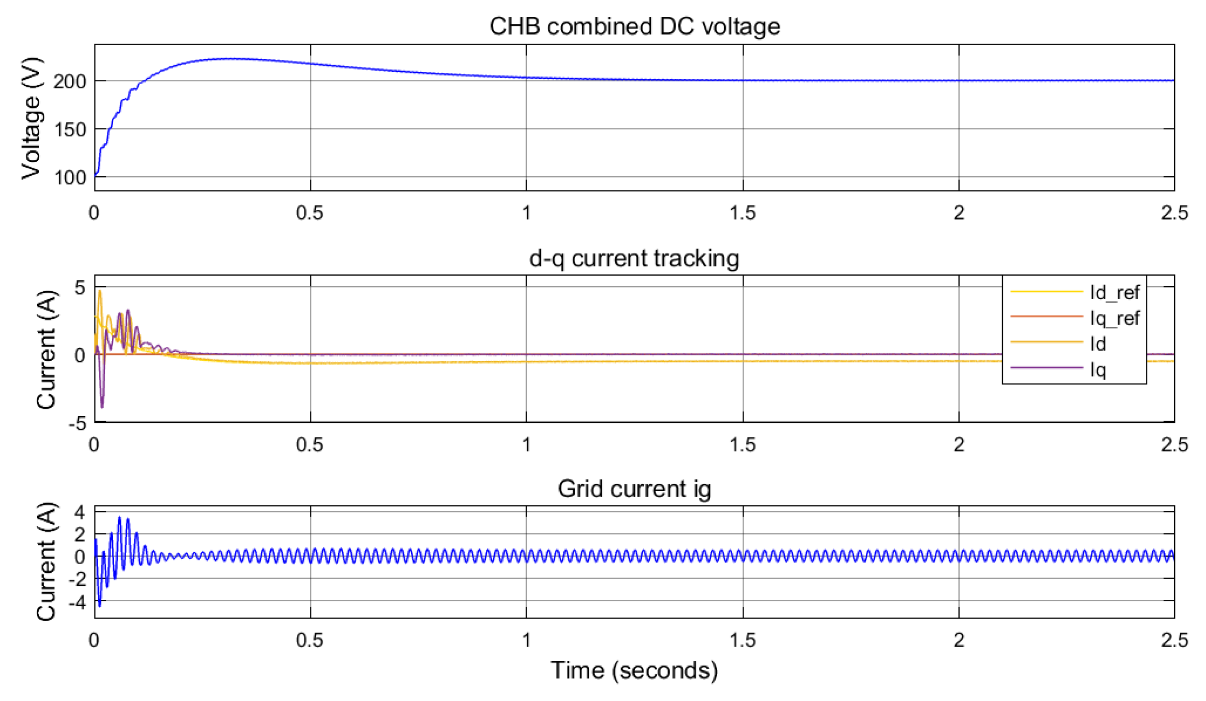
Figure 21 and Figure 22 show the CHB-combined DC voltage, d-q current tracking, and grid current, , under novel RNN control with phase-shifted modulation and level-shifted modulations, respectively.
The comparison between conventional PI-based vector control and novel RNN control indicated that the proposed RNN control has fewer oscillations and a fast response in d-q current waveforms, especially at the starting point, which can be recognized from the d-q current plots in Figure 19, Figure 20, Figure 21 and Figure 22.
5.4. Total Harmonic Distortion of the Inverter Voltage ()
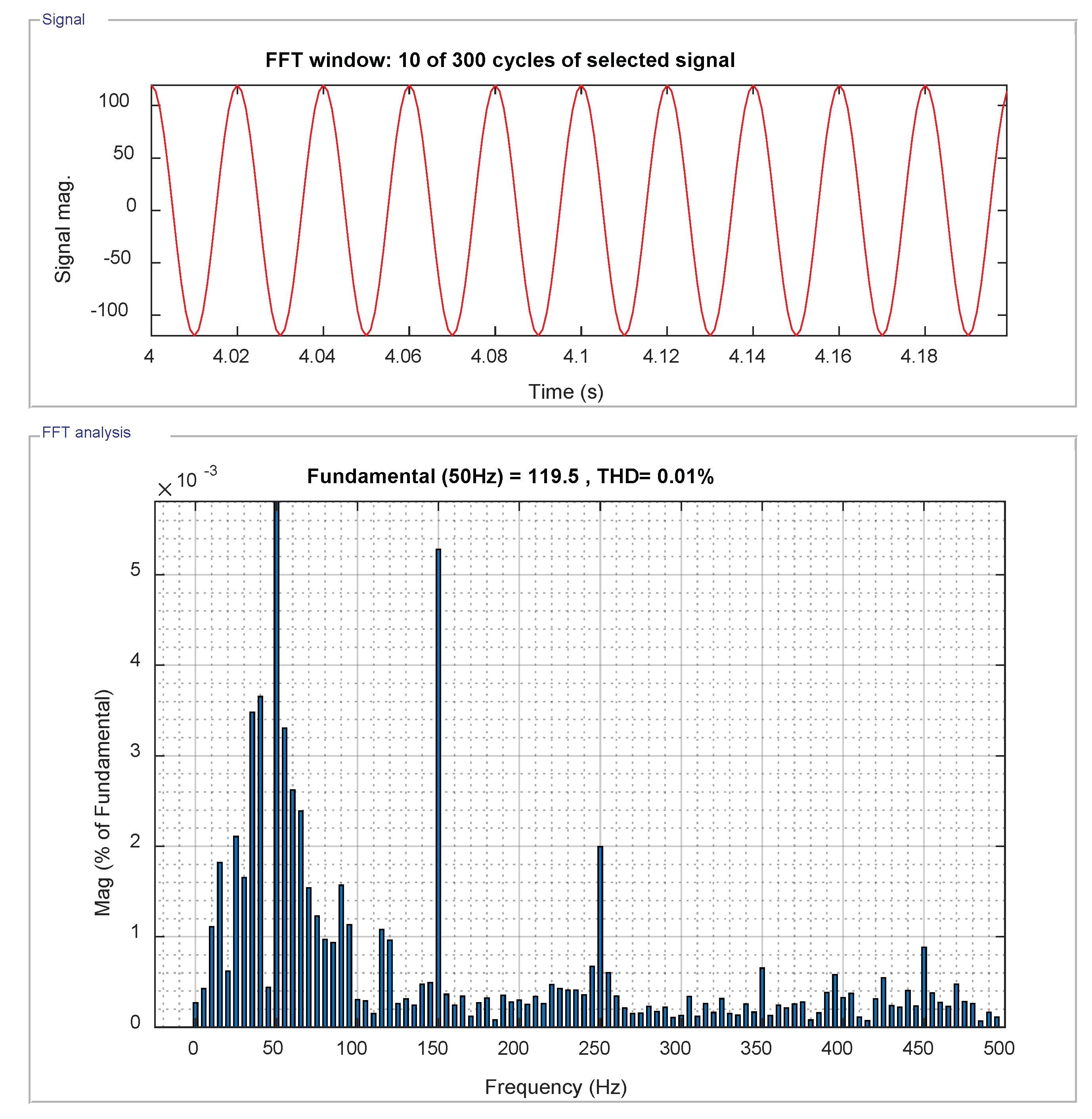
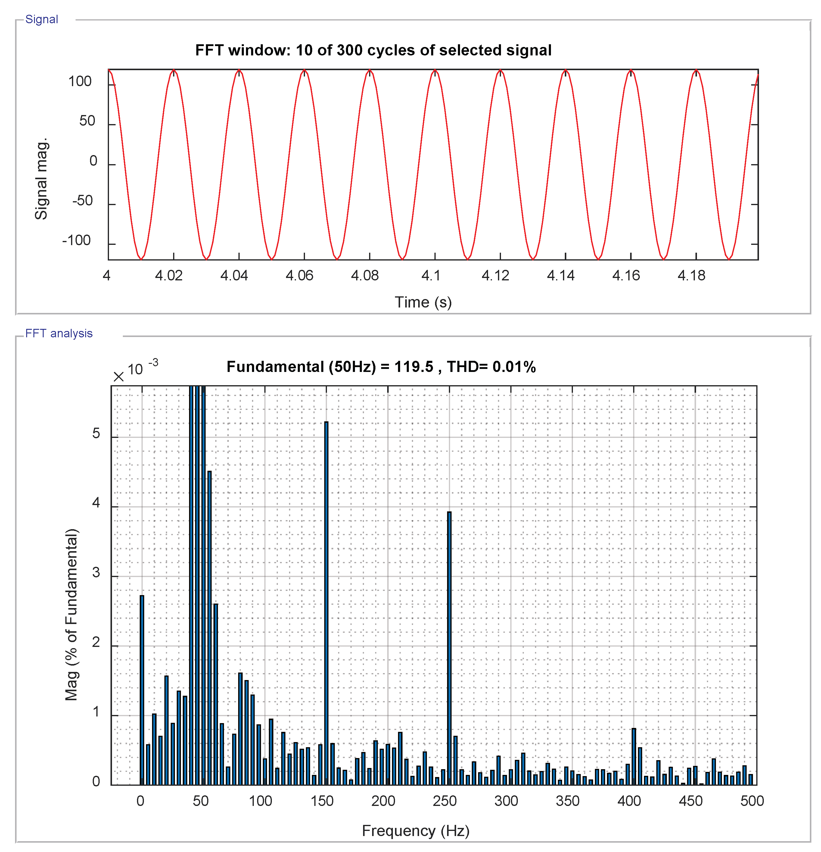
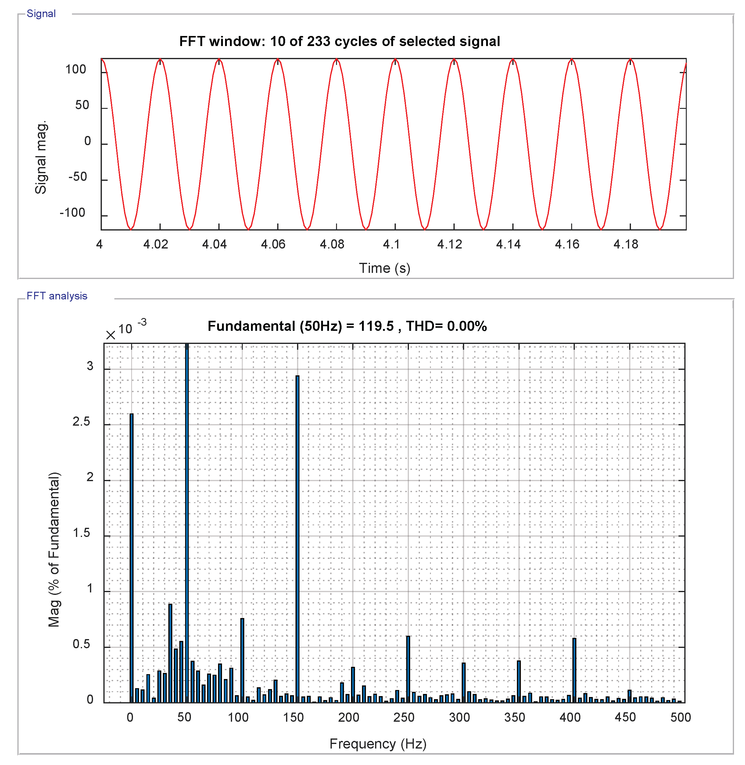
Figure 23 and Figure 24 show the calculated Total Harmonic Distortion (THD) of the filtered inverter voltage, , under conventional PI-based vector control with phase-shifted modulation and level-shifted modulation, respectively.
From Figure 23 and Figure 24, it can be seen that the THD of the inverter voltage, , is very small—around 0.01%. This indicates very good harmonic reduction ability of the LCL filter under conventional PI-based vector control with both phase-shifted modulation and level-shifted modulation.
5.5. Total Harmonic Distortion of Grid Current
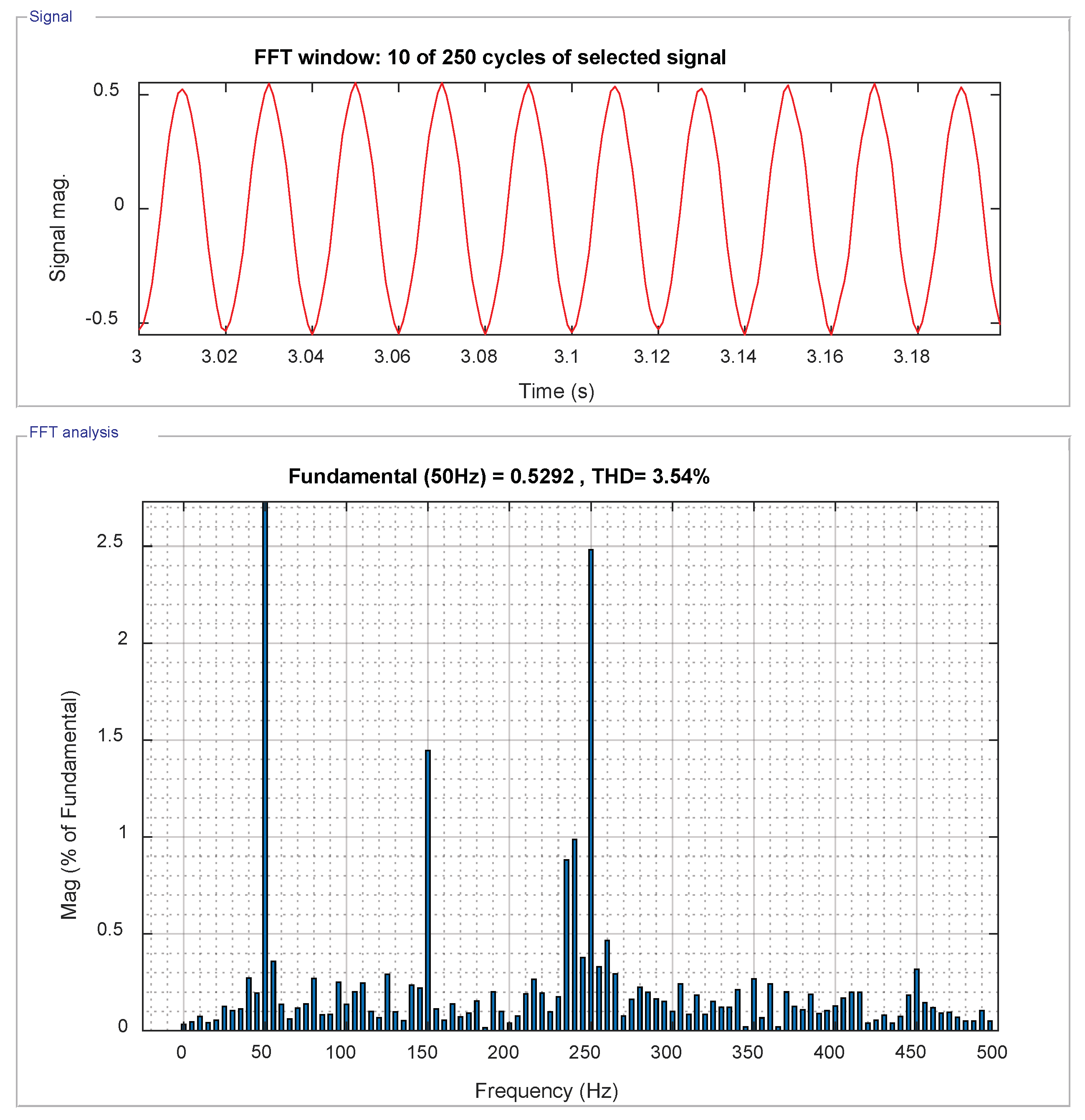
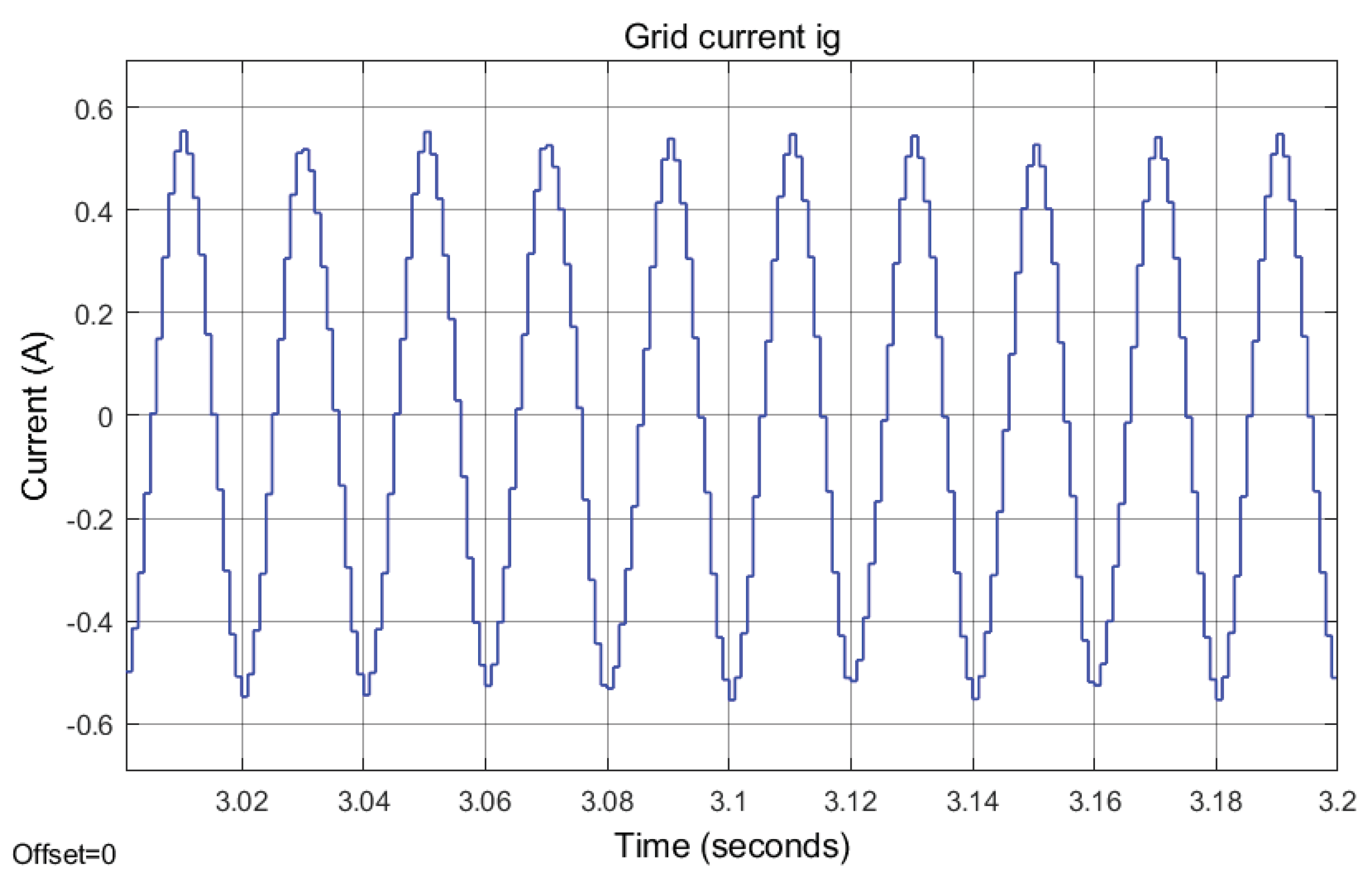
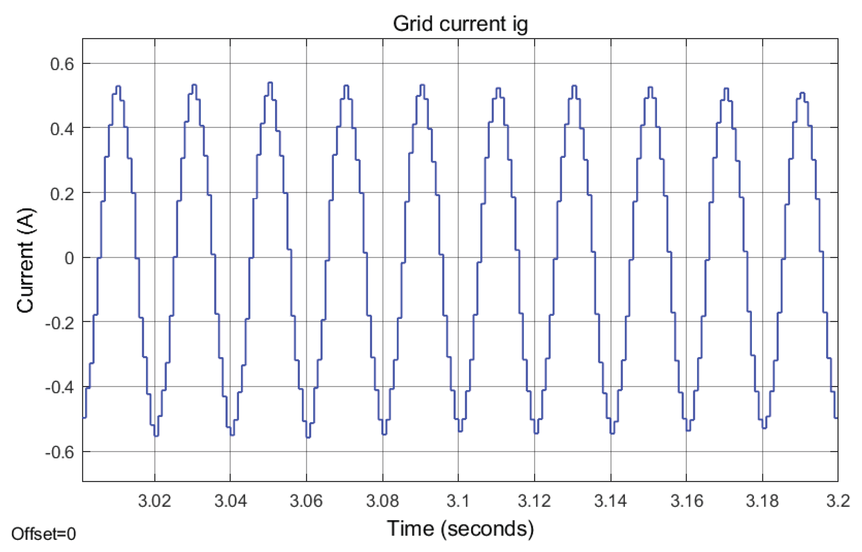
Figure 27 and Figure 28 show the grid current, , and the calculated Total Harmonic Distortion (THD) of the grid current, , under conventional PI-based vector control with phase-shifted modulation.
Figure 29 and Figure 30 show the grid current and the calculated Total Harmonic Distortion (THD) of the grid current, , under conventional PI-based vector control with level-shifted modulation.
Figure 31 and Figure 32 show the grid current, , and the calculated Total Harmonic Distortion (THD) of the grid current, , under novel RNN control with phase-shifted modulation.
6. Conclusions
This paper focused on a control system design with different carrier signal generation for the PWM of a grid-tied multilevel converter. The proposed RNN control system can be easily extended for higher level systems, i.e., seven, nine, eleven or more. In sum, this paper demonstrates the complete simulation process with the RNN-based closed-loop control strategy for both phase-shifted and level-shifted PWM inverters. The effectiveness and correctness of DC bus voltage balancing capability have been successfully validated through MATLAB simulation results. To further evaluate the feasibility of the NN technique, testing the proposed NN controller in a complete hardware-in-loop experiment with a microcontroller board and a solar panel is planned for future research.
Author Contributions
X.F. and S.L. contributed to the neural controller design and training, X.F. and A.A.H. developed the Simulink model, X.F., S.L., A.A.H., and R.C. all contributed to manuscript writing and revisions.
Funding
This research received no external funding.
Conflicts of Interest
The authors declare no conflict of interest.
Abbreviations
The following abbreviations are used in this manuscript:
| CHB | Cascaded H-Bridge |
| DP | Dynamic Programming |
| FATT | Forward Accumulation Through Time |
| GCC | Grid-Connected Converter |
| LM | Levenberg-Marquardt |
| NN | Neural Network |
| PI | Proportional Integral |
| PWM | Pulse Width Modulation |
| RNN | Recurrent Neural Network |
| THD | Total Harmonic Distortion |
References
- Blaabjerg, F.; Teodorescu, R.; Liserre, M.; Timbus, A.V. Overview of control and grid synchronization for distributed power generation systems. IEEE Trans. Ind. Electron. 2006, 53, 1398–1409. [Google Scholar] [CrossRef]
- Xue, Y.; Chang, L.; Kjær, S.B.; Bordonau, J.; Shimizu, T. Topologies of single-phase inverters for small distributed power generators: An overview. IEEE Trans. Power Electron. 2004, 19, 1305–1314. [Google Scholar] [CrossRef]
- Ji, S.; Zhang, Z.; Wang, F. Overview of high voltage SiC power semiconductor devices: Development and application. CES Trans. Electr. Mach. Syst. 2017, 1, 254–264. [Google Scholar]
- Patil, S.S.; Patil, U.V. Solar photovoltaic power conversion using modular multilevel converter. Int. J. Ind. Electron. Electr. Eng. 2016, 4, 117–122. [Google Scholar]
- Calais, M.; G.Agelidis, V.; Meinhardt, M. Multilevel converters for single-phase grid connected photovoltaic systems: An overview. Solar Energy 1999, 66, 325–335. [Google Scholar] [CrossRef]
- Krishnamoorthy, H.S.; Essakiappan, S.; Enjeti, P.N.; Balog, R.S.; Ahmed, S. A new multilevel converter for Megawatt scale solar photovoltaic utility integration. In Proceedings of the 2012 Twenty-Seventh Annual IEEE Applied Power Electronics Conference and Exposition (APEC), Orlando, FL, USA, 5–9 February 2012; pp. 1431–1438. [Google Scholar]
- Lai, J.; Peng, F. Multilevel converters—A new breed of power converters. IEEE Trans. Ind. Appl. 1996, 32, 2348–2356. [Google Scholar]
- Krug, D.; Bernet, S.; Fazel, S.S.; Jalili, K.; Malinowski, M. Comparison of 2.3-kV medium-voltage multilevel converters for industrial medium-voltage drives. IEEE Trans. Ind. Electron. 2007, 54, 2979–2992. [Google Scholar] [CrossRef]
- Essakiappan, S.; Krishnamoorthy, H.S.; Enjeti, P.N.; Balong, R.S.; Ahmed, S. Multilevel medium frequency link inverter for utility-scale photovoltaic integration. IEEE Trans. Power Electron. 2015, 30, 3674–3684. [Google Scholar] [CrossRef]
- Bellman, R.E. Dynamic Programming; Princeton University Press: Princeton, NJ, USA, 1957. [Google Scholar]
- Balakrishnan, S.N.; Biega, V. Adaptive-critic-based neural networks for aircraft optimal control. J. Guid. Control Dyn. 1996, 19, 893–898. [Google Scholar] [CrossRef]
- Prokhorov, D.V.; Wunsch, D.C. Adaptive critic designs. IEEE Trans. Neural Netw. 1997, 8, 997–1007. [Google Scholar] [CrossRef] [PubMed] [Green Version]
- Wang, F.; Zhang, H.; Liu, D. Adaptive dynamic programming: An introduction. IEEE Comput. Intell. Mag. 2009, 4, 39–47. [Google Scholar] [CrossRef]
- Li, S.; Fairbank, M.; Wunsch, D.C.; Alonso, E. Vector Control of a Grid-Connected Rectifier/Inverter Using an Artificial Neural Network. In Proceedings of the IEEE World Congress on Computational Intelligence, Brisbane, Australia, 10–15 June 2012; pp. 1–7. [Google Scholar]
- Li, S.; Fairbank, M.; Johnson, C.; Wunsch, D.C.; Alonso, E.; Proaño, J.L. Artificial neural networks for control of a grid-connected rectifier/inverter under disturbance, dynamic and power converter switching conditions. IEEE Trans. Neural Netw. Learn. Syst. 2014, 25, 738–750. [Google Scholar] [PubMed]
- Fu, X.; Li, S.; Jaithwa, I. Implement Optimal Vector Control for LCL-Filter-Based Grid-Connected Converters by Using Recurrent Neural Networks. IEEE Trans. Ind. Electron. 2015, 62, 4443–4454. [Google Scholar] [CrossRef]
- Fu, X.; Li, S. Control of single-phase grid-connected converters with LCL filters using recurrent neural network and conventional control methods. IEEE Trans. Power Electron. 2016, 31, 5354–5364. [Google Scholar] [CrossRef]
- Zhang, R.; Cardinal, M.; Szczesny, P.; Dame, M. A grid simulator with control of single-phase power converters in D-Q rotating frame. In Proceedings of the IEEE Power Electronics Specialists Conference, Cairns, Australia, 23–27 June 2002; pp. 1431–1436. [Google Scholar]
- Liserre, M.; Blaabjerg, F.; Hansen, S. Design and control of an LCL filter-based three-phase active rectifier. IEEE Trans. Ind. Appl. 2005, 41, 1281–1291. [Google Scholar] [CrossRef]
- Dannehl, J.; Wessels, C.; Fuchs, F.W. Limitations of voltage-oriented PI current control of grid-connected PWM rectifiers with LCL filters. IEEE Trans. Ind. Electron. 2009, 56, 380–388. [Google Scholar] [CrossRef]
- Blasko, V.; Kaura, V. A novel control to actively damp resonance in input LC filter of a three-phase voltage source converter. IEEE Trans. Ind. Appl. 1997, 33, 542–550. [Google Scholar] [CrossRef]
- Peña-Alzola, R.; Liserre, M.; Blaabjerg, F.; Sebastián, R.; Dannehl, J.; Fuchs, F.W. Analysis of the passive damping losses in LCL-filter-based grid converters. IEEE Trans. Power Electron. 2013, 28, 2642–2646. [Google Scholar] [CrossRef]
- Dannehl, J.; Liserre, M.; Fuchs, F.W. Filter-based active damping of voltage source converters with LCL filter. IEEE Trans. Ind. Electron. 2011, 58, 3623–3633. [Google Scholar] [CrossRef]
- Jalili, K.; Bernet, S. Design of LCL filters of active-front-end two level voltage-source converters. IEEE Trans. Ind. Electron. 2009, 56, 1674–1689. [Google Scholar] [CrossRef]
- Li, S.; Haskew, T.A.; Hong, Y.K.; Xu, L. Direct-current vector control of three-phase grid-connected rectifier-inverter. Electr. Power Syst. Res. 2011, 81, 357–366. [Google Scholar] [CrossRef]
- Franquelo, L.G.; Rodrigues, J.; Leon, J.I.; Kouro, S.; Portillo, R.; Prats, M.A.M. The age of multilevel converters arrives. IEEE Ind. Electron. Mag. 2008, 2, 1932–4529. [Google Scholar] [CrossRef]
- Caciotta, M.; Giarnetti, S.; Leccese, F.; Orioni, B.; Oreggia, M.; Pucci, C.; Rametta, S. Flavors mapping by Kohonen network classification of panel tests of extra virgin olive oil. Meas. J. Int. Meas. Confed. 2016, 78, 366–372. [Google Scholar] [CrossRef]
- Caciotta, M.; Giarnetti, S.; Leccese, F. Hybrid Neural Network System for Electric Load Forecasting of Telecomunication Station. In Proceedings of the 19th XIX IMEKO World Congress Fundamental and Applied Metrology, Lisbon, Portugal, 6–11 September 2009; pp. 657–661. [Google Scholar]
- Hagan, M.T.; Demuth, H.B.; Beale, M.H. Neural Network Design; PWS Publishing: Boston, MA, USA, 2002. [Google Scholar]
- Mohan, N.; Undeland, T.M.; Robbins, W.P. Power Electronics: Converters, Applications, and Design, 3rd ed.; John Wiley and Sons: Chichester, West Sussex, UK, 2002. [Google Scholar]
- Hagan, M.T.; Menhaj, M.B. Training feedforward networks with the marquardt algorithm. IEEE Trans. Neural Netw. 1994, 5, 989–993. [Google Scholar] [CrossRef] [PubMed]
- Fu, X.; Li, S.; Fairbank, M.; Wunsch, D.C.; Alonso, E. Training recurrent neural networks with the Levenberg-Marquardt algorithm for optimal control of a grid-connected converter. IEEE Trans. Neural Netw. Learn. Syst. 2015, 26, 1900–1912. [Google Scholar] [CrossRef] [PubMed]
- Levenberg, K. A method for the solution of certain non-linear problems in least squares. Q. J. Appl. Math. 1994, 2, 164–168. [Google Scholar] [CrossRef]
- Marquardt, D.W. An algorithm for least-squares estimation of nonlinear parameters. J. Soc. Ind. Appl. Math. 1963, 11, 431–441. [Google Scholar] [CrossRef]
- Teodorescu, R.; Liserre, M.; Rodriguez, P. Grid Converters for Photovoltaic and Wind Power Systems; John Wiley and Sons: Chichester, West Sussex, UK, 2011. [Google Scholar]
- Castilla, M.; Miret, J.; Matas, J.; de Vicuña, L.G.; Guerrero, J.M. A review of single-phase grid-connected inverters for photovoltaic modules. IEEE Trans. Ind. Appl. 2005, 41, 4492–4501. [Google Scholar]
- Castilla, M.; Miret, J.; Matas, J.; de Vicuña, L.G.; Guerrero, J.M. Control design guidelines for single-phase grid-connected photovoltaic inverters with damped resonant harmonic compensators. IEEE Trans. Ind. Electron. 2009, 56, 4492–4501. [Google Scholar] [CrossRef]
Figure 1.
The schematic of a five-level grid-tied inverter.
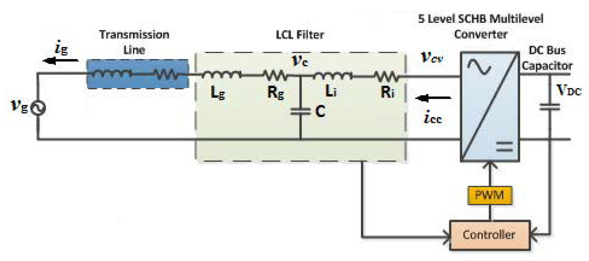
Figure 2.
The schematic of a five-level grid-tied inverter.
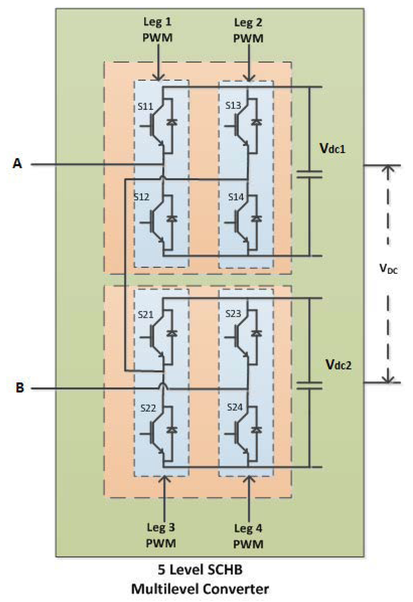
Figure 3.
The tuning process of the PI controllers.

Figure 4.
The PI-based vector control for the single-phase grid-tied inverter system.

Figure 5.
The phase shifted carrier signal with modulation.
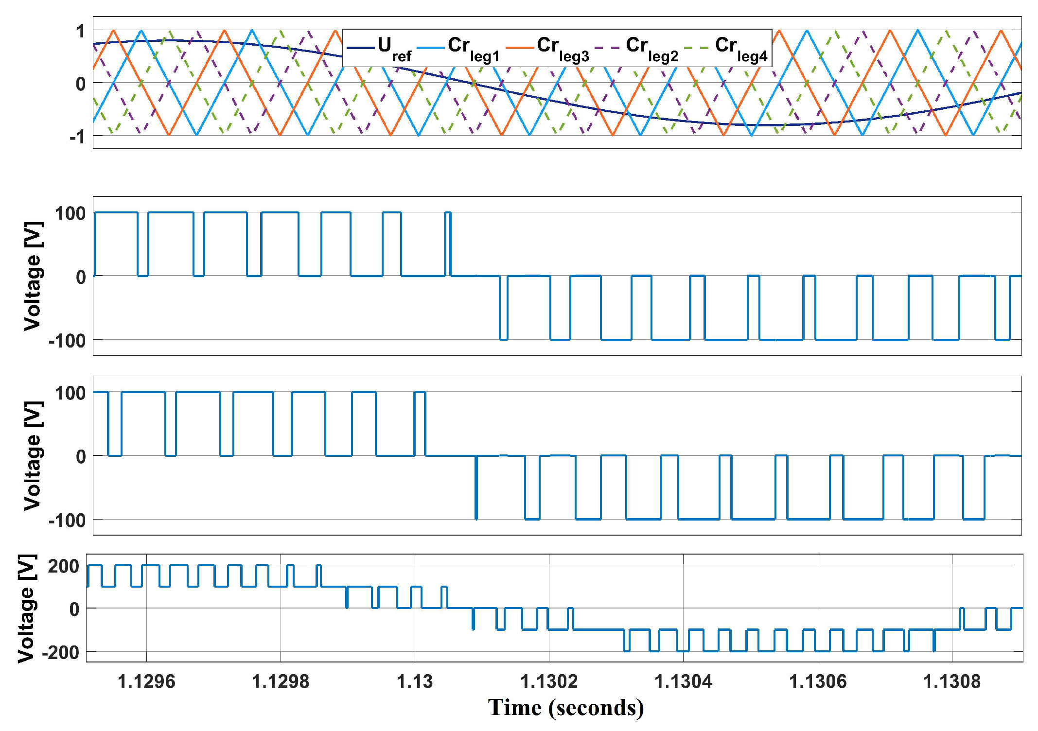
Figure 6.
The level shifted carrier signal with modulation.

Figure 7.
NN current-loop controller structure.
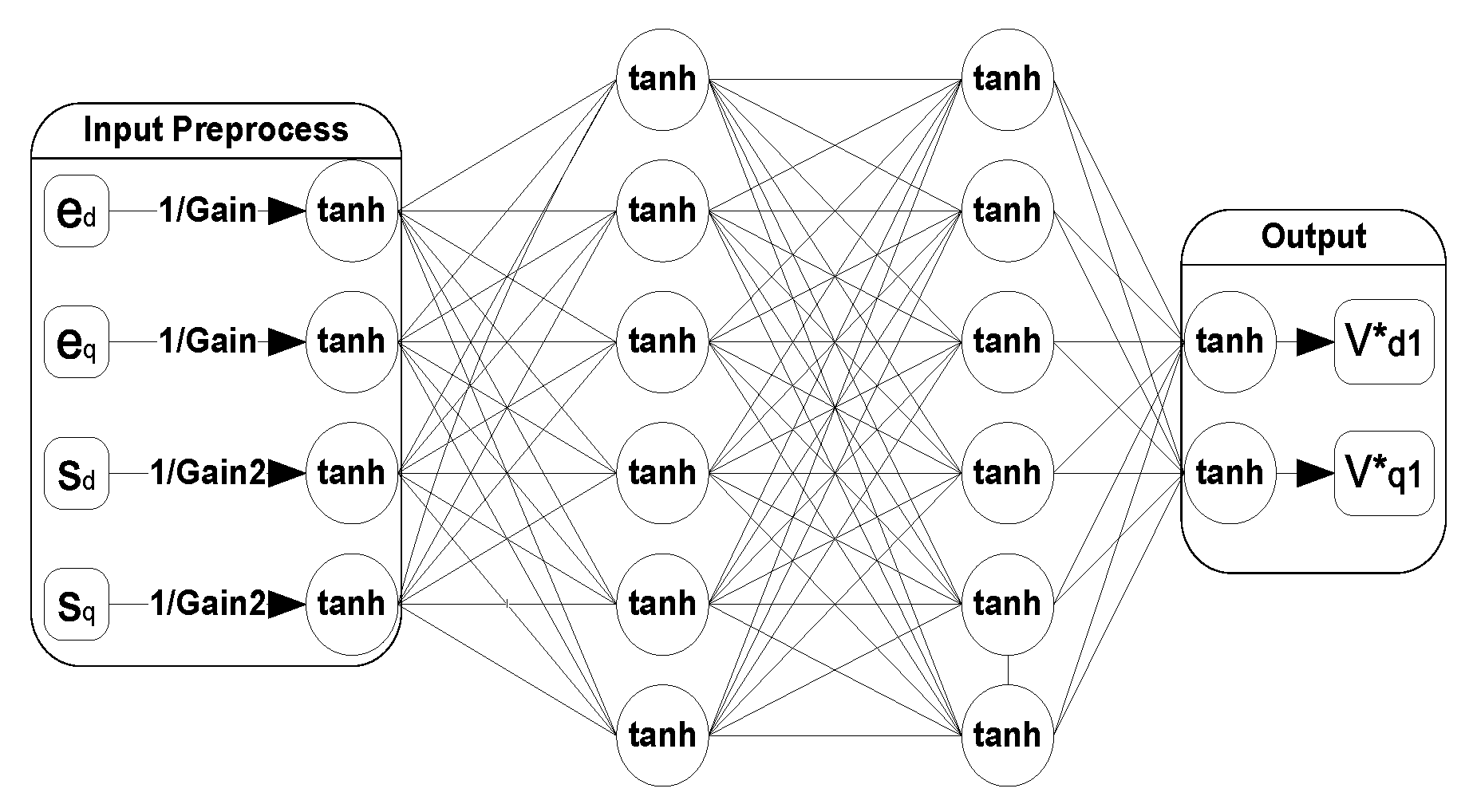
Figure 8.
The NN controller training in a closed loop control system.

Figure 9.
Illustration of the proposed Forward Accumulation Through Time (FATT) algorithm for training an NN controller.
Figure 9.
Illustration of the proposed Forward Accumulation Through Time (FATT) algorithm for training an NN controller.
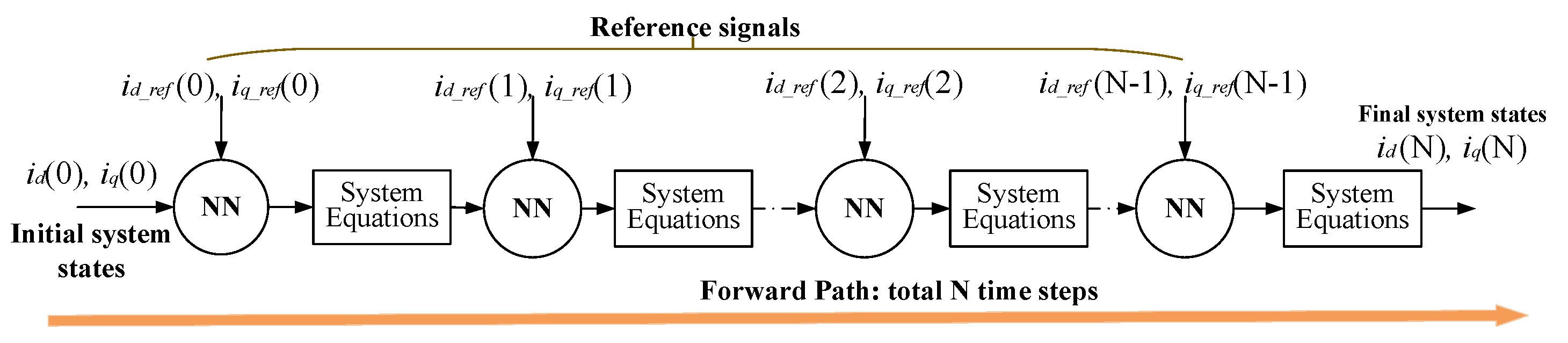
Figure 10.
The developed Simulink model of the Recurrent Neural Network (RNN) control & PI-based vector control for a five-level grid-tied converter.
Figure 10.
The developed Simulink model of the Recurrent Neural Network (RNN) control & PI-based vector control for a five-level grid-tied converter.
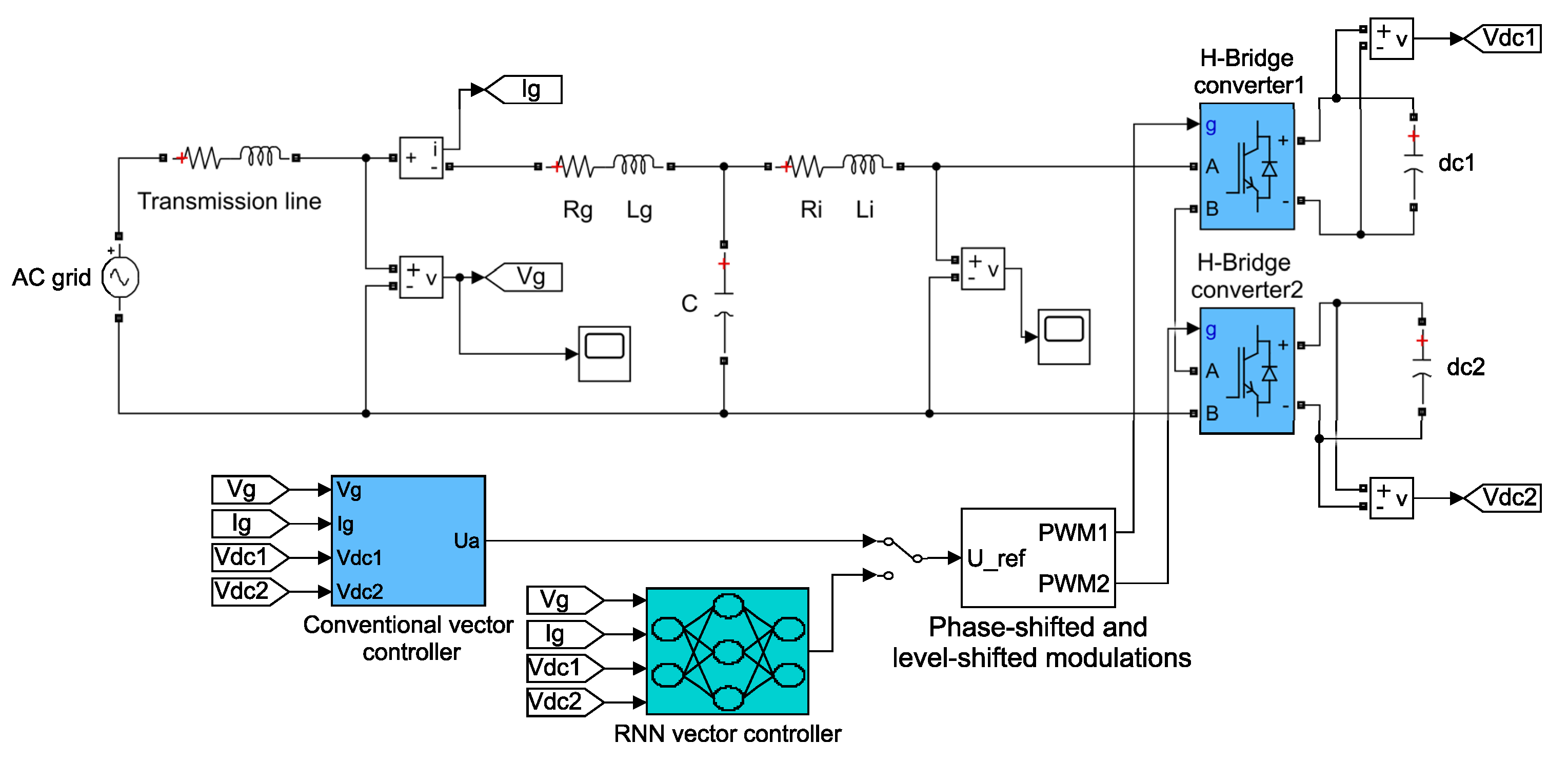
Figure 11.
Five-level CHB voltage under conventional PI-based vector control with phase-shifted modulation.
Figure 11.
Five-level CHB voltage under conventional PI-based vector control with phase-shifted modulation.

Figure 12.
Five-level CHB voltage under conventional PI-based vector control with level-shifted modulation.
Figure 12.
Five-level CHB voltage under conventional PI-based vector control with level-shifted modulation.

Figure 13.
Five-level CHB voltage under novel RNN control with phase-shifted modulation.

Figure 14.
Five-level CHB voltage under novel RNN control with level-shifted modulation.

Figure 15.
CHB DC voltage tracking under conventional PI-based vector control with phase-shifted modulation.
Figure 15.
CHB DC voltage tracking under conventional PI-based vector control with phase-shifted modulation.
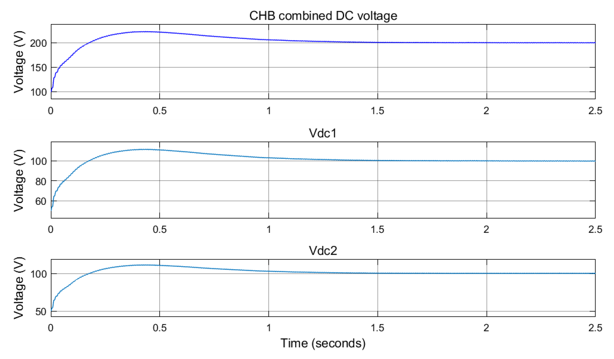
Figure 16.
CHB DC voltage tracking under conventional PI-based vector control with level-shifted modulation.
Figure 16.
CHB DC voltage tracking under conventional PI-based vector control with level-shifted modulation.
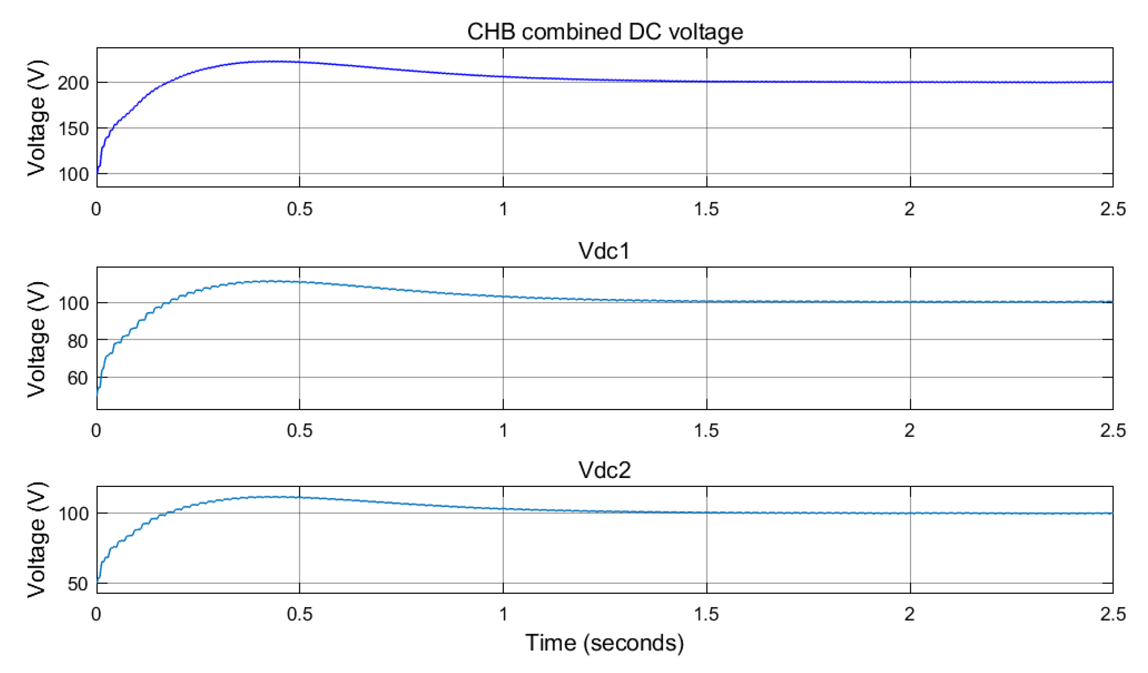
Figure 17.
CHB DC voltage tracking under novel RNN control with phase-shifted modulation.
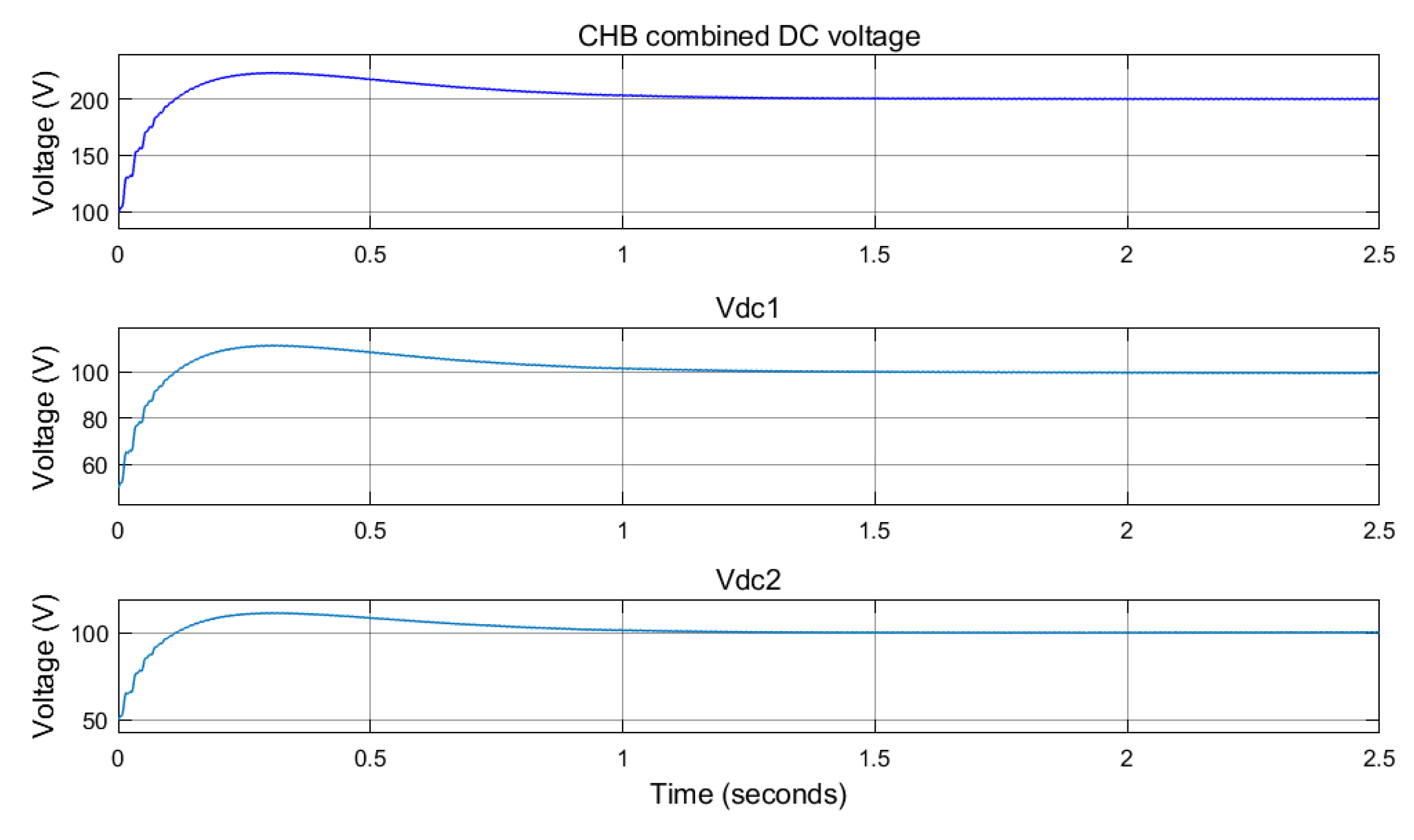
Figure 18.
CHB DC voltage tracking under novel RNN control with level-shifted modulations.
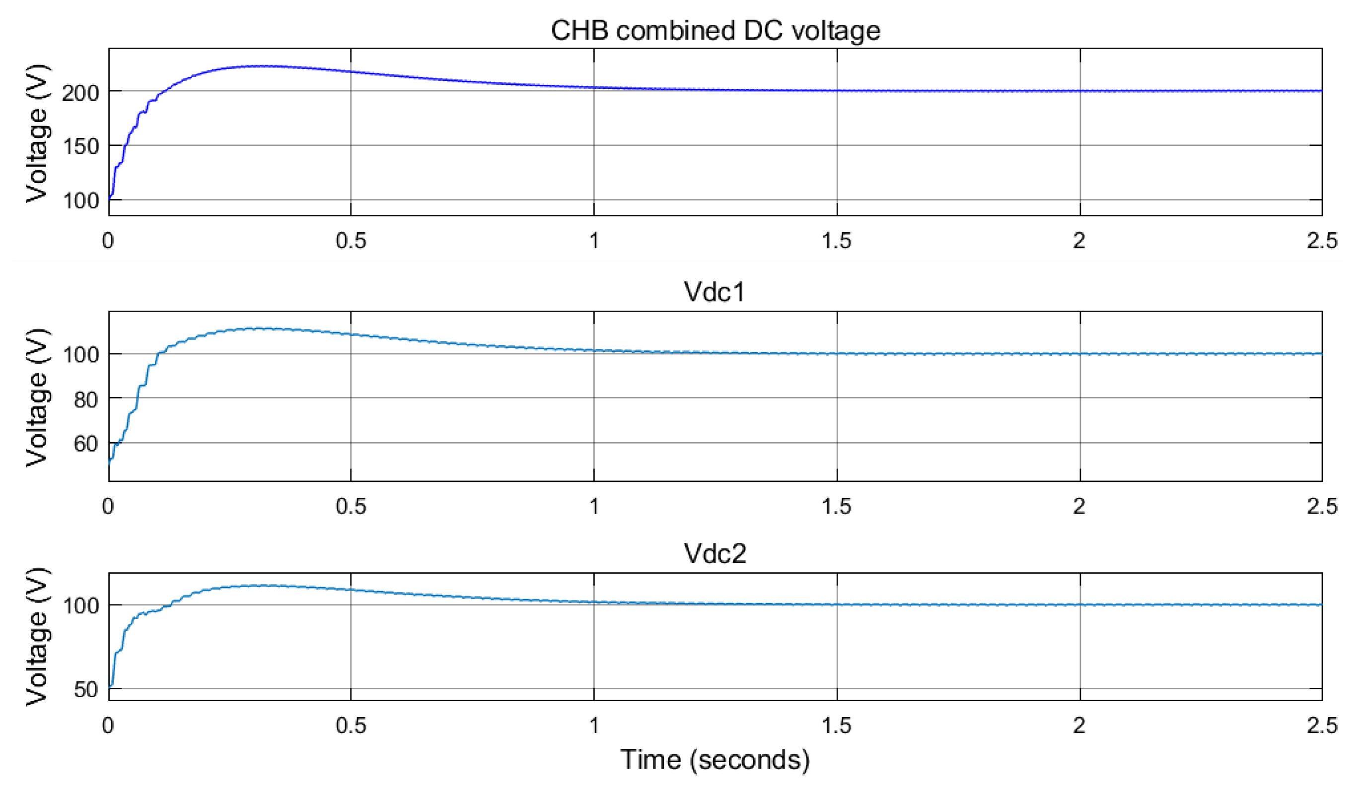
Figure 19.
CHB combined DC voltage tracking, d-q current tracking, and grid current under conventional PI-based vector control with phase-shifted modulations.
Figure 19.
CHB combined DC voltage tracking, d-q current tracking, and grid current under conventional PI-based vector control with phase-shifted modulations.

Figure 20.
CHB-combined DC voltage tracking, d-q current tracking, and grid current under conventional PI-based vector control with level-shifted modulations.
Figure 20.
CHB-combined DC voltage tracking, d-q current tracking, and grid current under conventional PI-based vector control with level-shifted modulations.
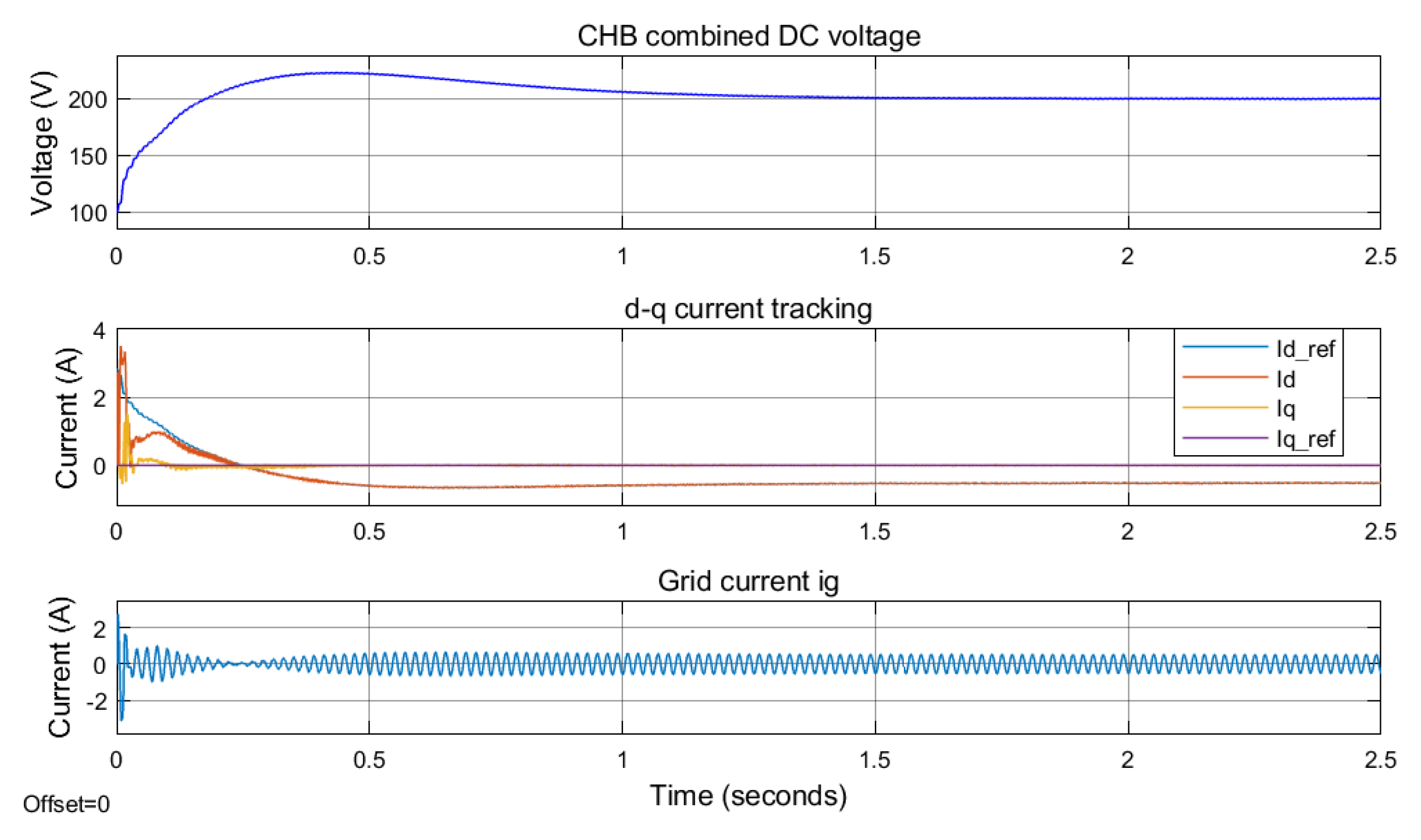
Figure 21.
CHB-combined DC voltage tracking, d-q current tracking, and grid current, under novel RNN control with phase-shifted modulations.
Figure 21.
CHB-combined DC voltage tracking, d-q current tracking, and grid current, under novel RNN control with phase-shifted modulations.
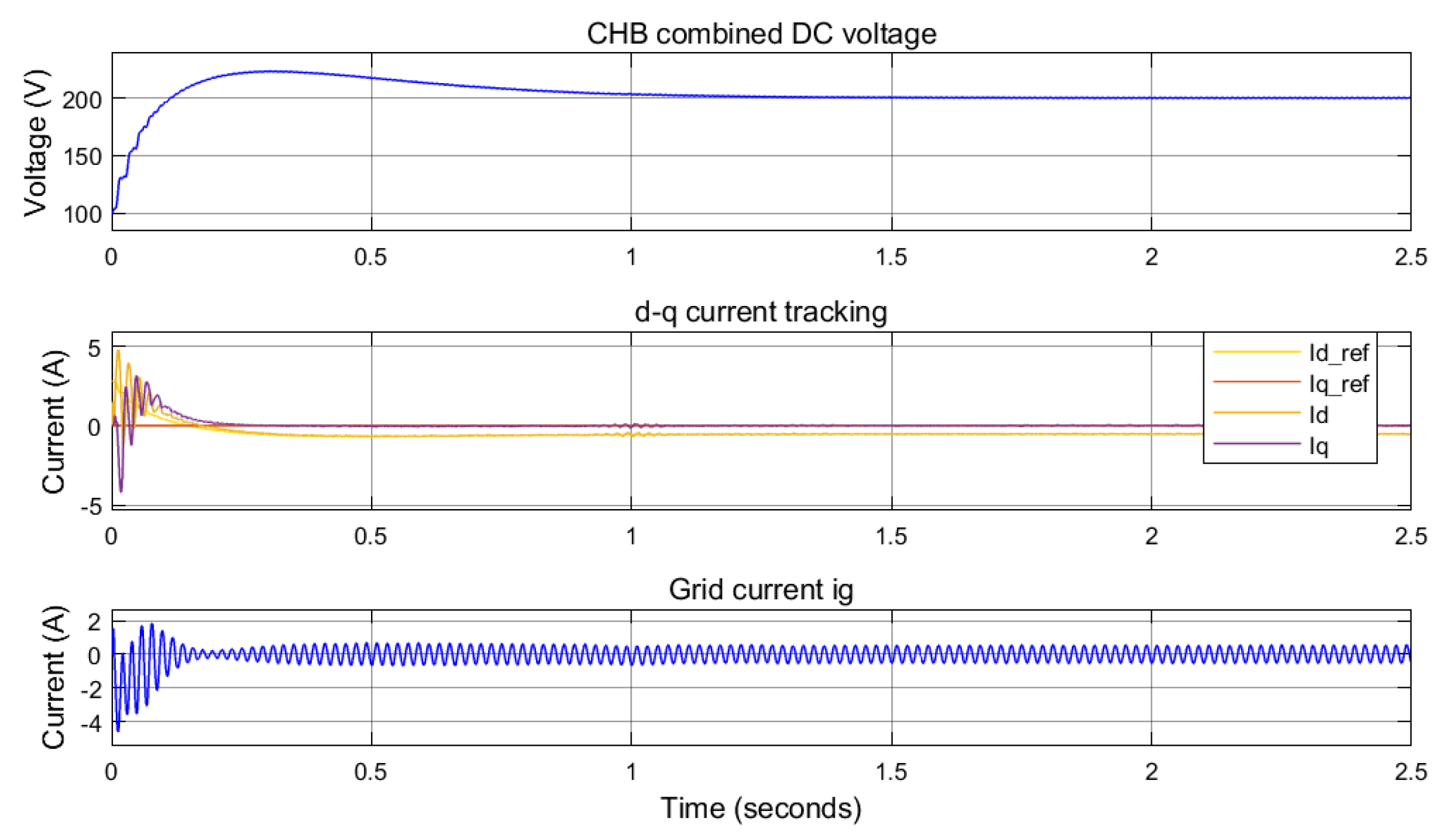
Figure 22.
CHB-combined DC voltage tracking, d-q current tracking, and grid current, , under novel RNN control with level-shifted modulations.
Figure 22.
CHB-combined DC voltage tracking, d-q current tracking, and grid current, , under novel RNN control with level-shifted modulations.

Figure 23.
Total Harmonic Distortion (THD) of the inverter voltage, , under conventional PI-based vector control with phase-shifted modulation.
Figure 23.
Total Harmonic Distortion (THD) of the inverter voltage, , under conventional PI-based vector control with phase-shifted modulation.

Figure 24.
Total Harmonic Distortion (THD) of the inverter voltage, , under conventional PI-based vector control with level-shifted modulation.
Figure 24.
Total Harmonic Distortion (THD) of the inverter voltage, , under conventional PI-based vector control with level-shifted modulation.

Figure 25.
Total Harmonic Distortion (THD) of the inverter voltage, , under novel RNN control with phase-shifted modulation.
Figure 25.
Total Harmonic Distortion (THD) of the inverter voltage, , under novel RNN control with phase-shifted modulation.
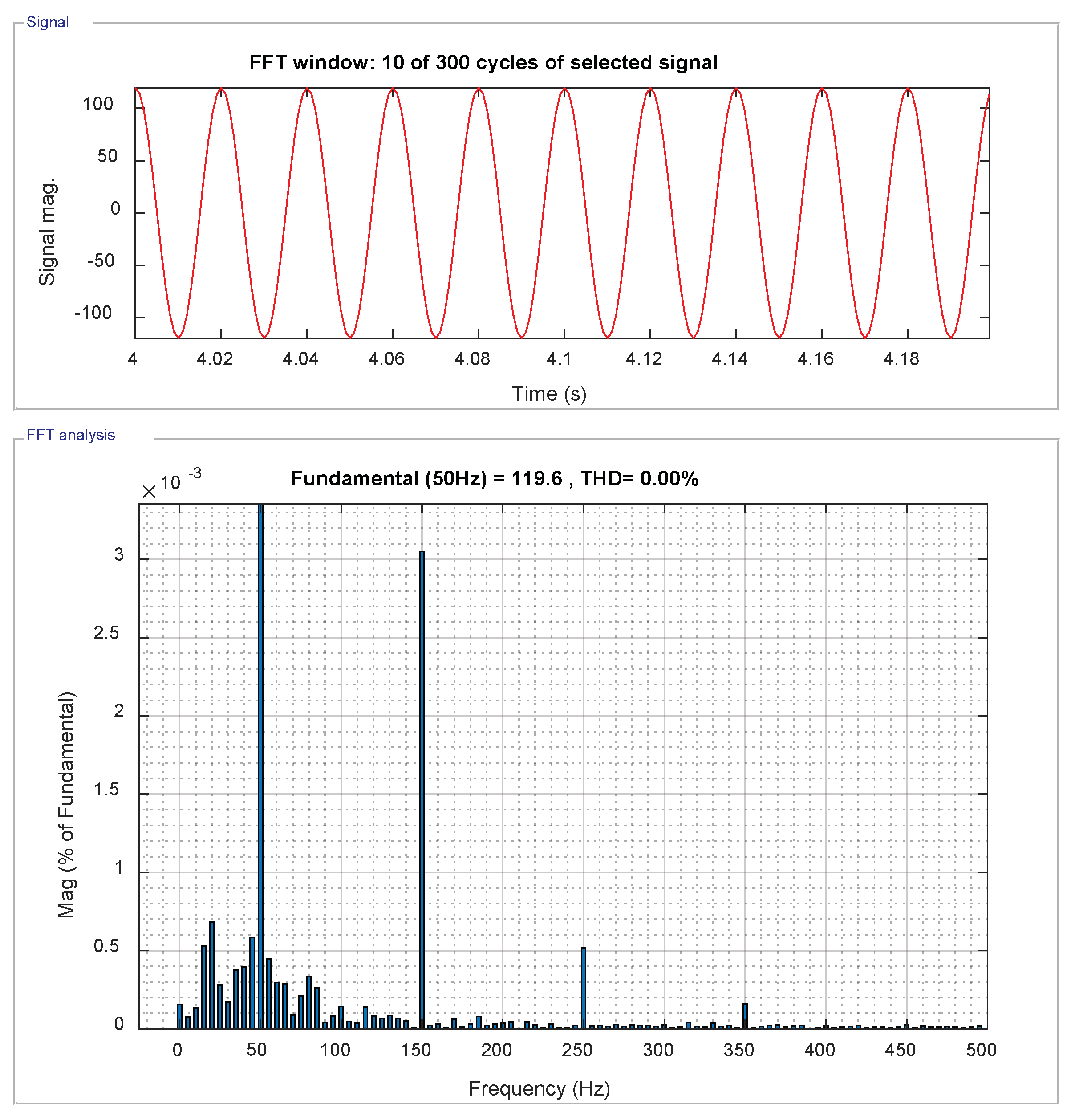
Figure 26.
Total Harmonic Distortion (THD) of the inverter voltage, , under novel RNN control with level-shifted modulation.
Figure 26.
Total Harmonic Distortion (THD) of the inverter voltage, , under novel RNN control with level-shifted modulation.

Figure 27.
Grid current, , under conventional PI-based vector control with phase-shifted modulation.
Figure 27.
Grid current, , under conventional PI-based vector control with phase-shifted modulation.
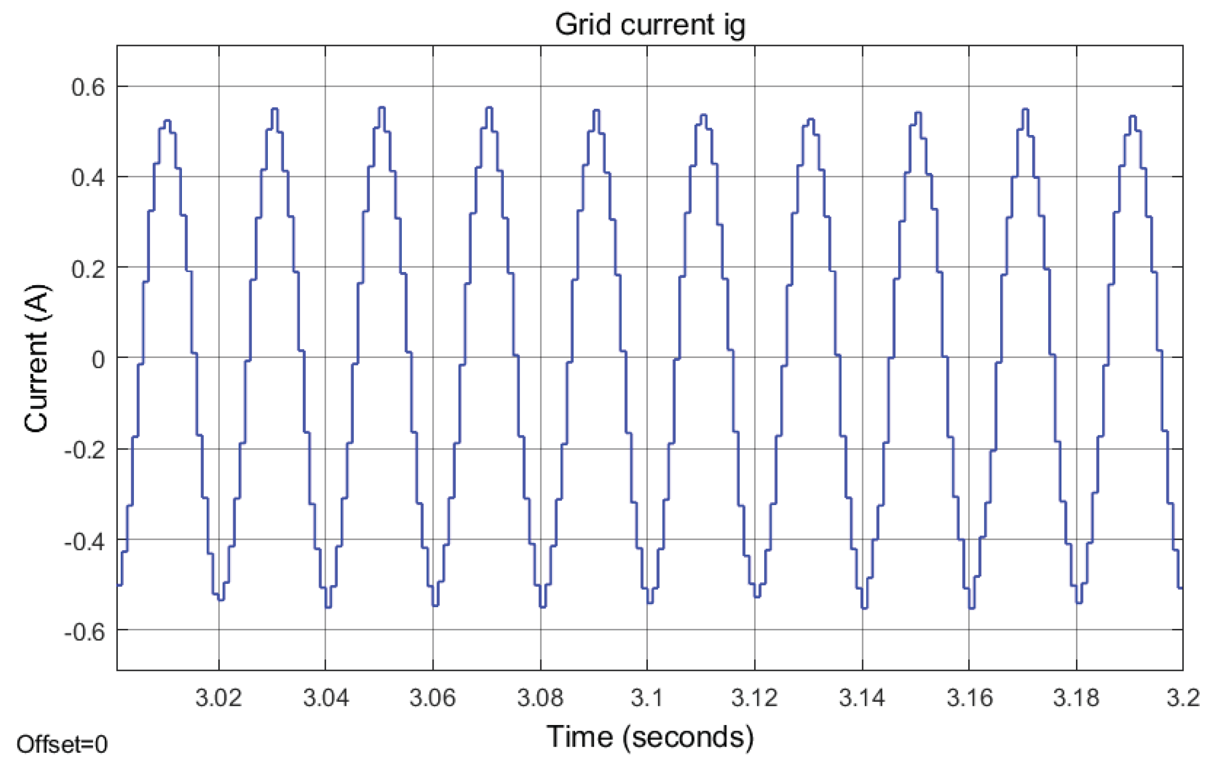
Figure 28.
Total Harmonic Distortion (THD) of the grid current, , under conventional PI-based vector control with phase-shifted modulation.
Figure 28.
Total Harmonic Distortion (THD) of the grid current, , under conventional PI-based vector control with phase-shifted modulation.

Figure 29.
Grid current, , under conventional PI-based vector control with level-shifted modulation.
Figure 29.
Grid current, , under conventional PI-based vector control with level-shifted modulation.
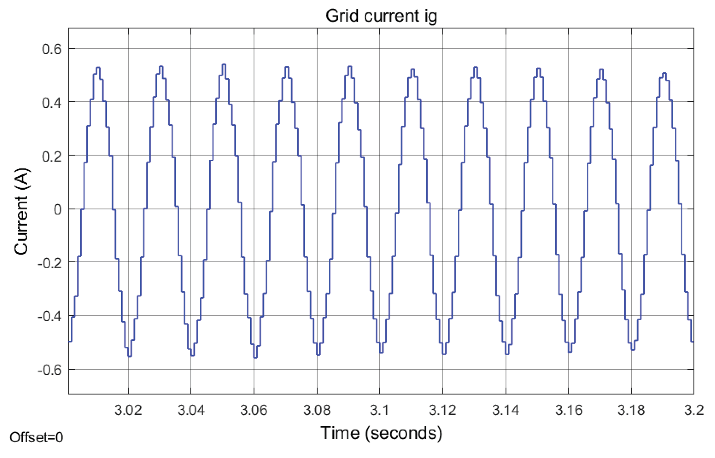
Figure 30.
Total Harmonic Distortion (THD) of the grid current, , under conventional PI-based vector control with level-shifted modulation.
Figure 30.
Total Harmonic Distortion (THD) of the grid current, , under conventional PI-based vector control with level-shifted modulation.
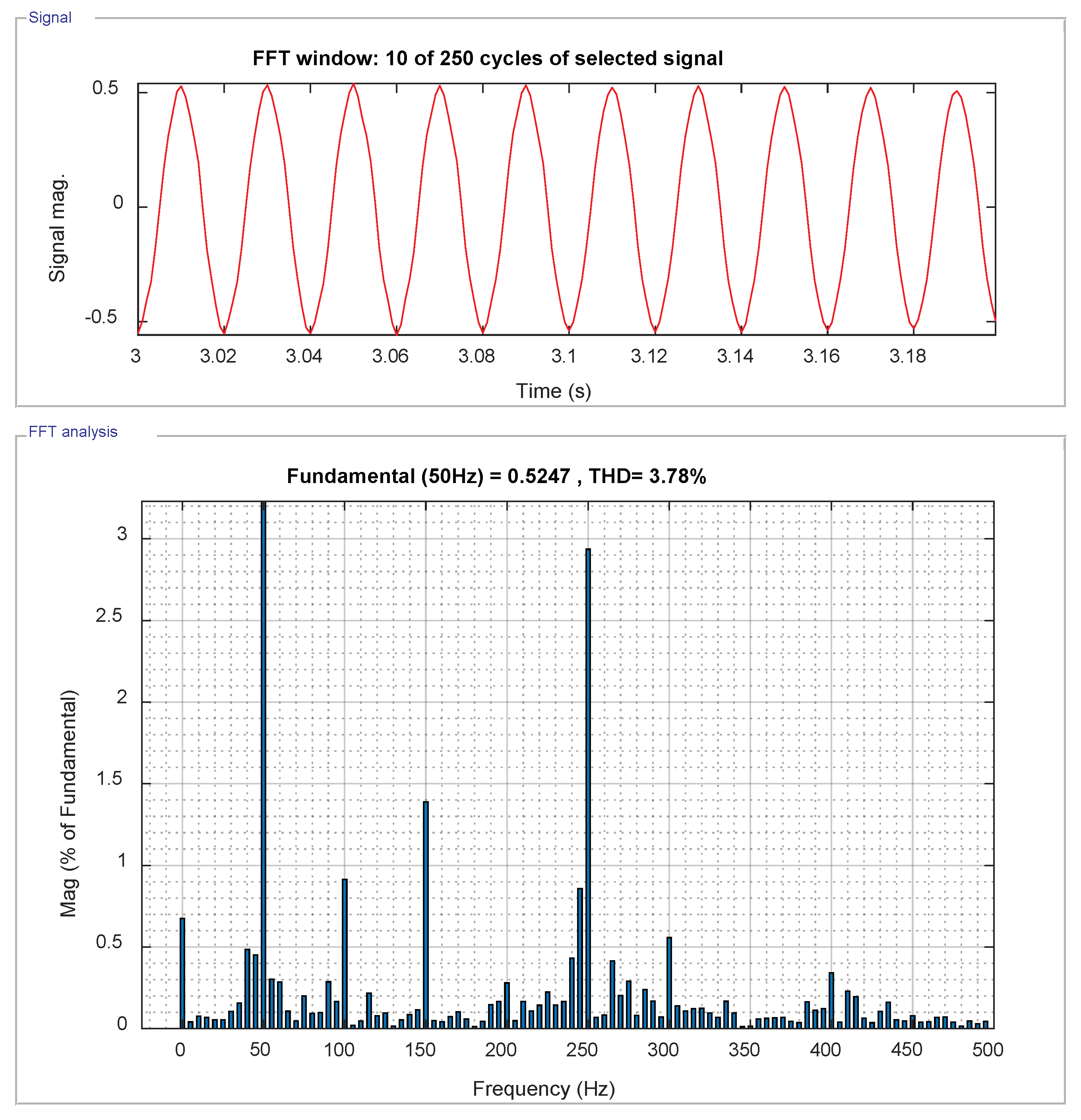
Figure 31.
Grid current, , under novel RNN control with phase-shifted modulation.

Figure 32.
Total Harmonic Distortion (THD) under novel RNN control with phase-shifted modulation.
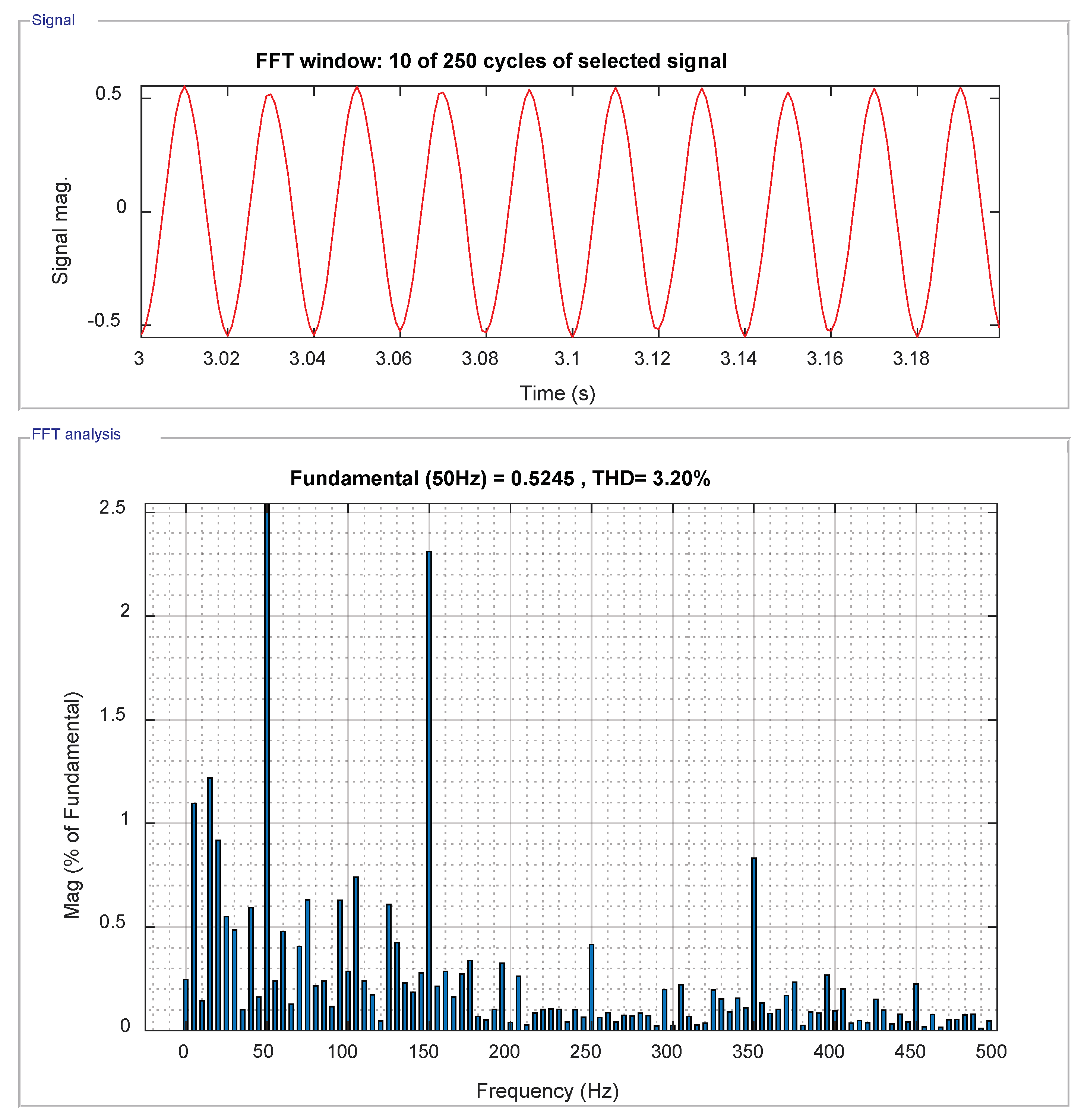
Figure 33.
Grid current, , under novel RNN control with level-shifted modulation.

Figure 34.
Total Harmonic Distortion (THD) under novel RNN control with level-shifted modulation.


Table 1.
Single-phase five level grid-tied Cascaded H-Bridge (CHB) inverter system parameters.
| Symbol | Quantity | Value | Units |
|---|---|---|---|
| nominal grid voltage (rms) | 120 | V | |
| f | nominal grid frequency | 50 | Hz |
| DC-link voltage | 200 | V | |
| & | LCL filter inductor | 25 | mH |
| & | LCL filter resistor | 0.25 | |
| C | LCL filter parallel capacitor | 2.2 | F |
| & | DC capacitors | 1630 | F |
| the PWM switching frequency | 6000 | Hz | |
| the sampling time | 1 | ms |
© 2018 by the authors. Licensee MDPI, Basel, Switzerland. This article is an open access article distributed under the terms and conditions of the Creative Commons Attribution (CC BY) license (http://creativecommons.org/licenses/by/4.0/).
Share and Cite
MDPI and ACS Style
Fu, X.; Li, S.; Hadi, A.A.; Challoo, R. Novel Neural Control of Single-Phase Grid-Tied Multilevel Inverters for Better Harmonics Reduction. Electronics 2018, 7, 111. https://doi.org/10.3390/electronics7070111
AMA Style
Fu X, Li S, Hadi AA, Challoo R. Novel Neural Control of Single-Phase Grid-Tied Multilevel Inverters for Better Harmonics Reduction. Electronics. 2018; 7(7):111. https://doi.org/10.3390/electronics7070111
Chicago/Turabian StyleFu, Xingang, Shuhui Li, Abdullah Al Hadi, and Rajab Challoo. 2018. "Novel Neural Control of Single-Phase Grid-Tied Multilevel Inverters for Better Harmonics Reduction" Electronics 7, no. 7: 111. https://doi.org/10.3390/electronics7070111
Note that from the first issue of 2016, this journal uses article numbers instead of page numbers. See further details here.