Design of a Building-Integrated Photovoltaic System with a Novel Bi-Reflector PV System (BRPVS) and Optimal Control Mechanism: An Experimental Study


 ,
,  , ,
, , 

Abstract
:1. Introduction
2. System Components and Development
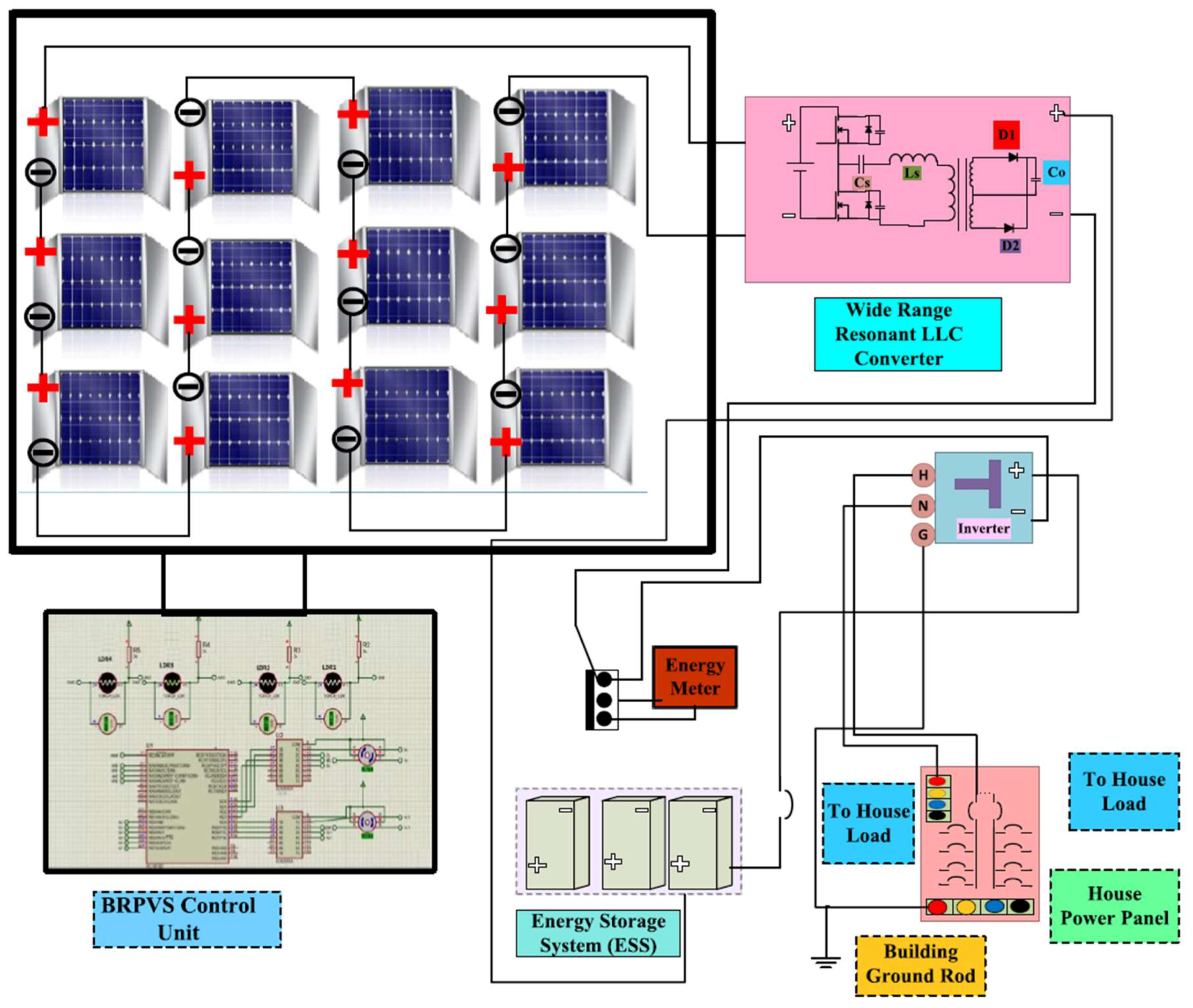
2.1. An Overview of Proposed BRPVS
2.2. Components of Designed BRPVS System for BIPV
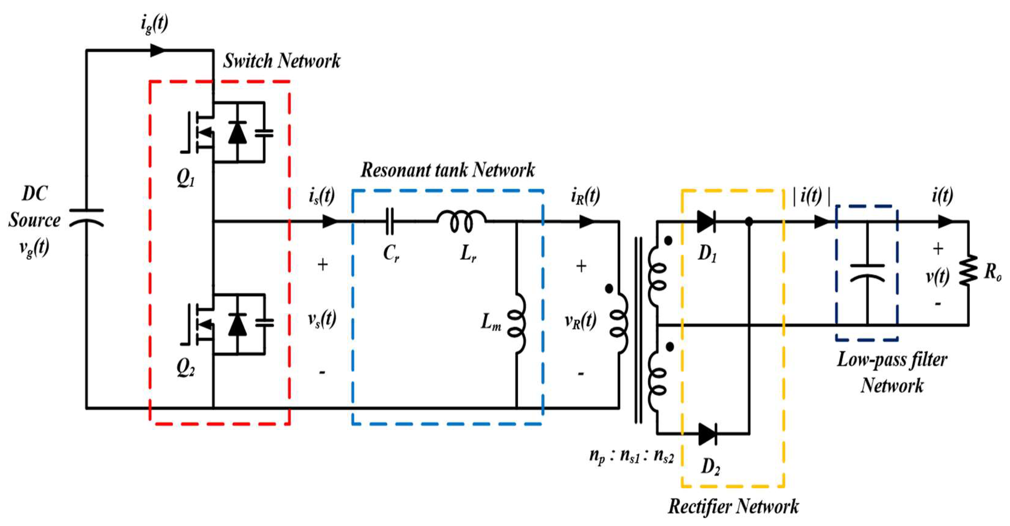
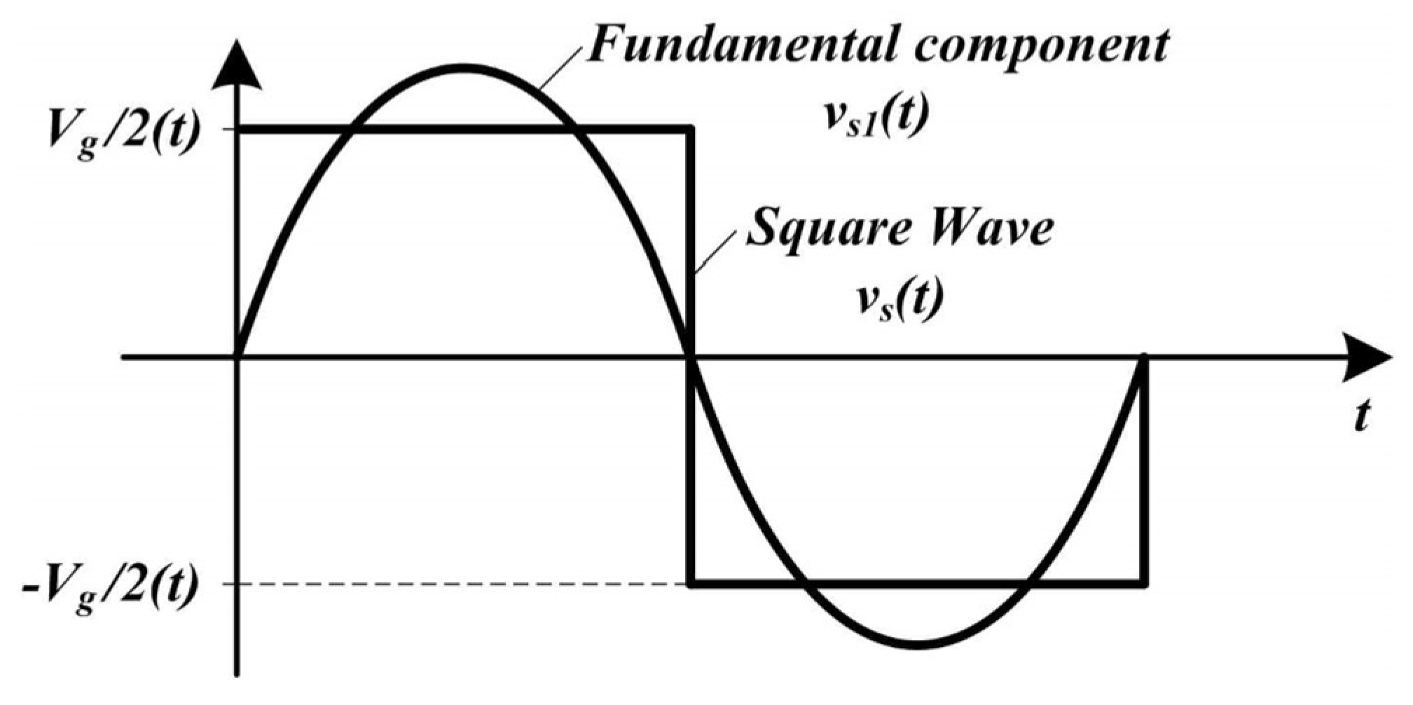
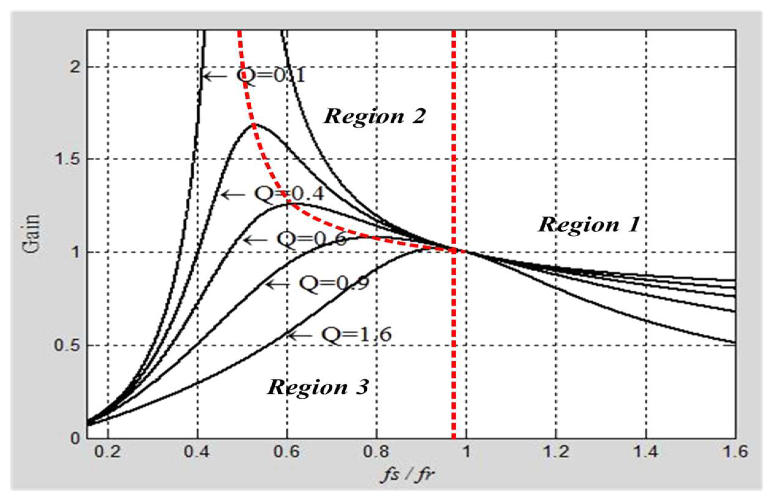
2.2.1. Wide Range Medium Power LLC Converter
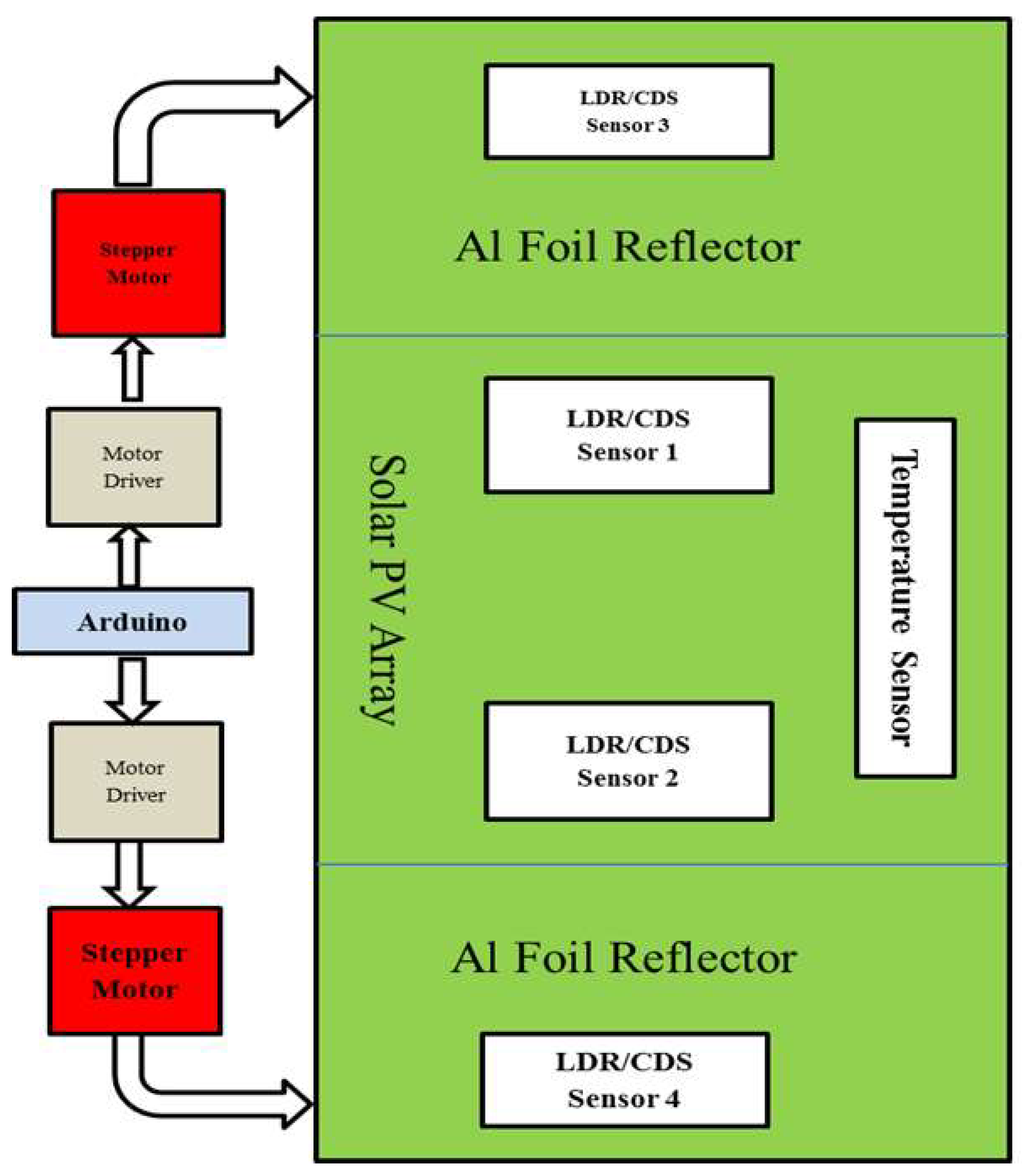
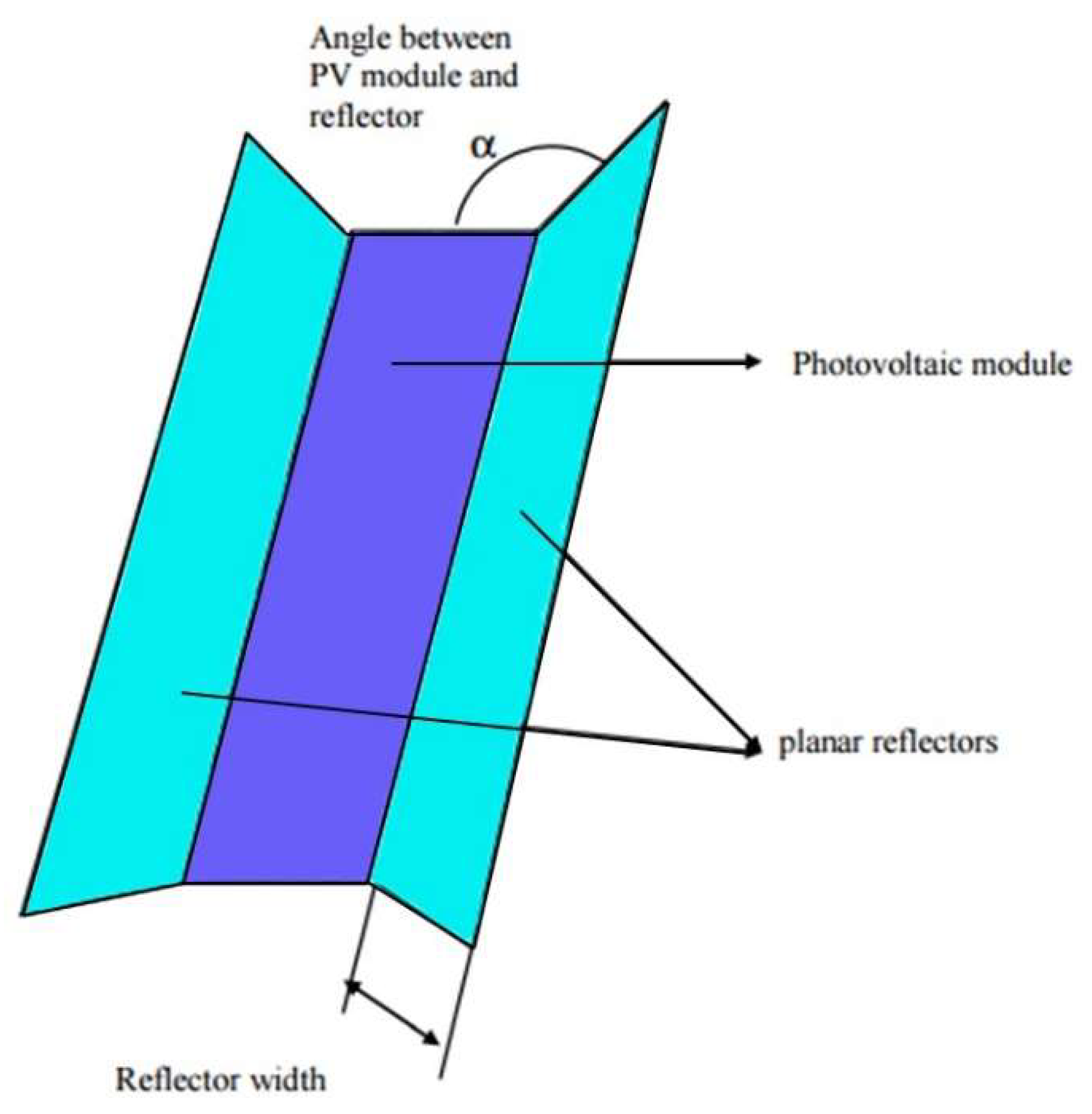
2.2.2. Al-Foil Based Bi Reflector System (Al-BRS)
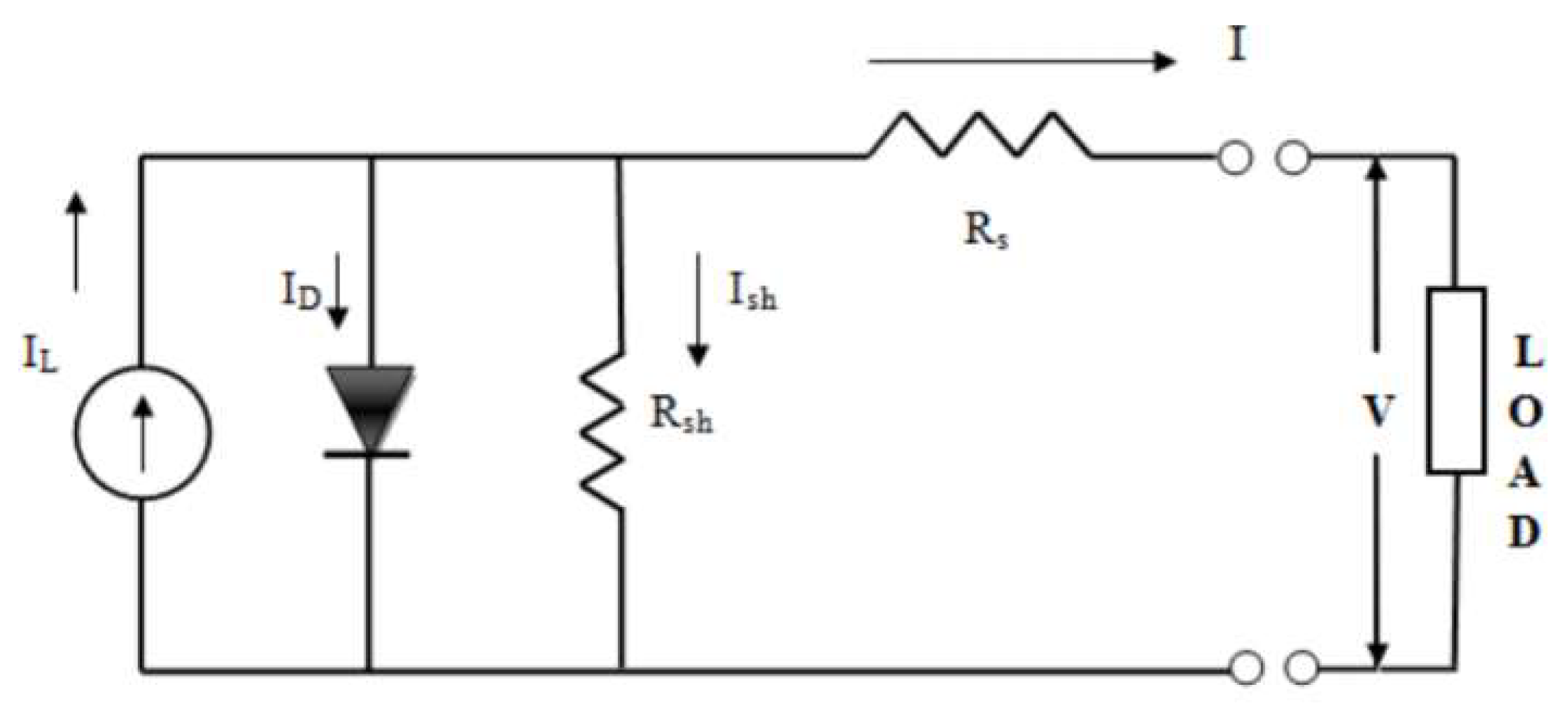
Electrical Modeling
Optical Modeling
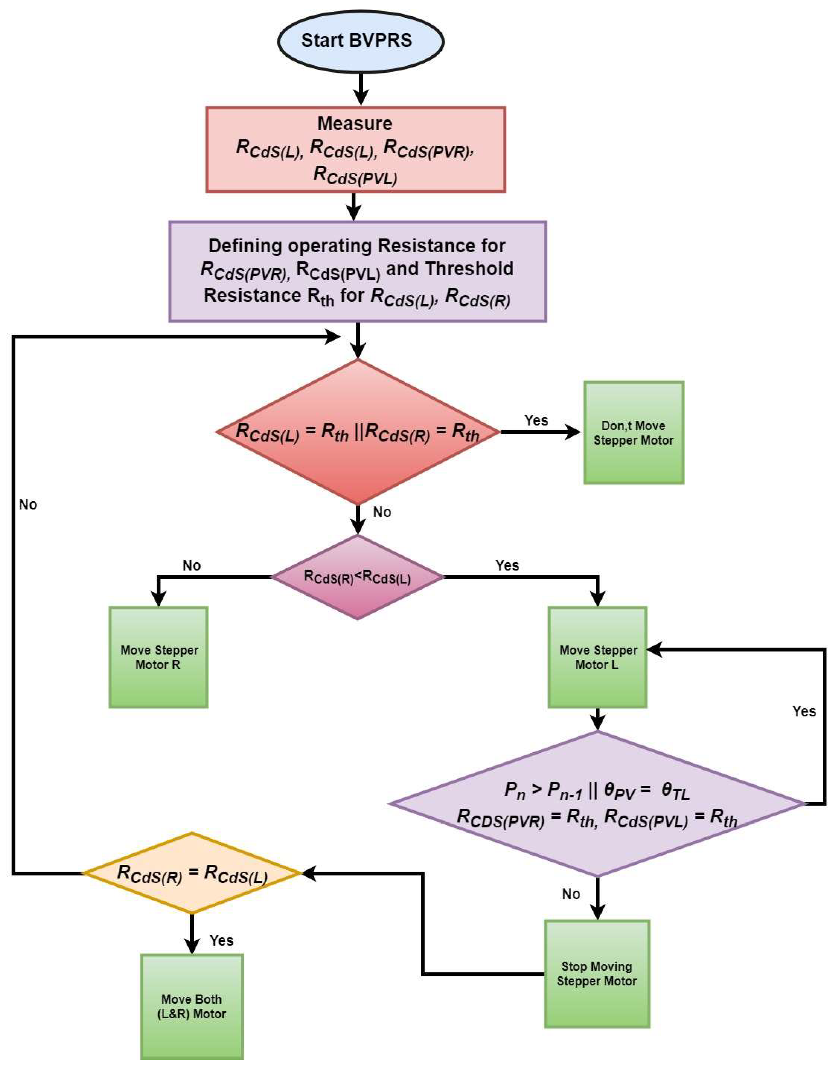
Control Mechanism
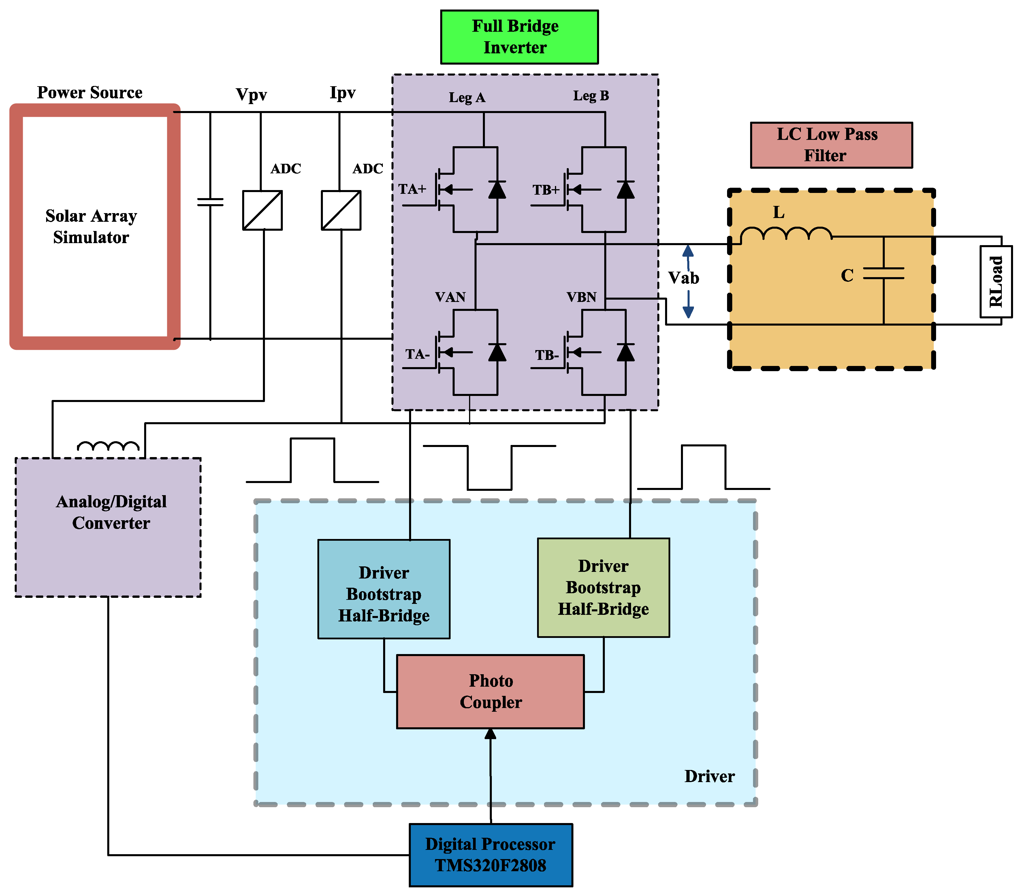
2.2.3. Inverter (Full-Bridge)
2.2.4. Energy Storage System (ESS)
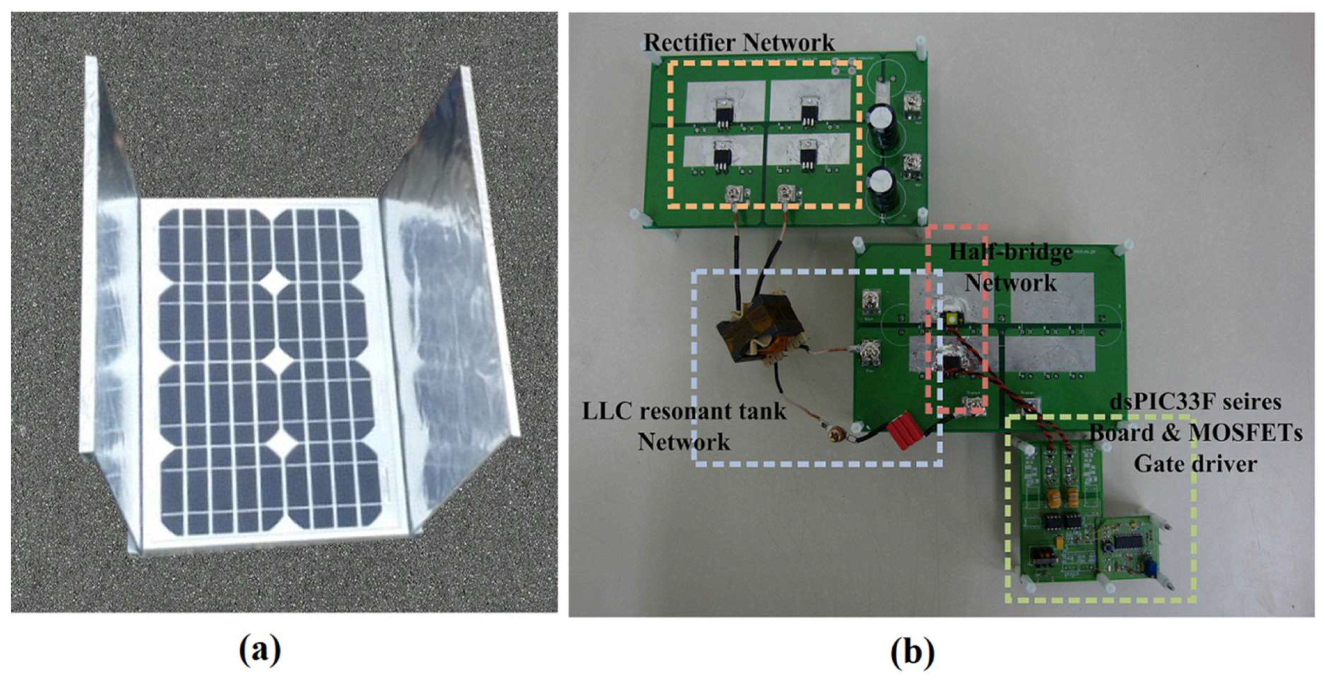
3. Experimental Setup
4. Results and Discussion
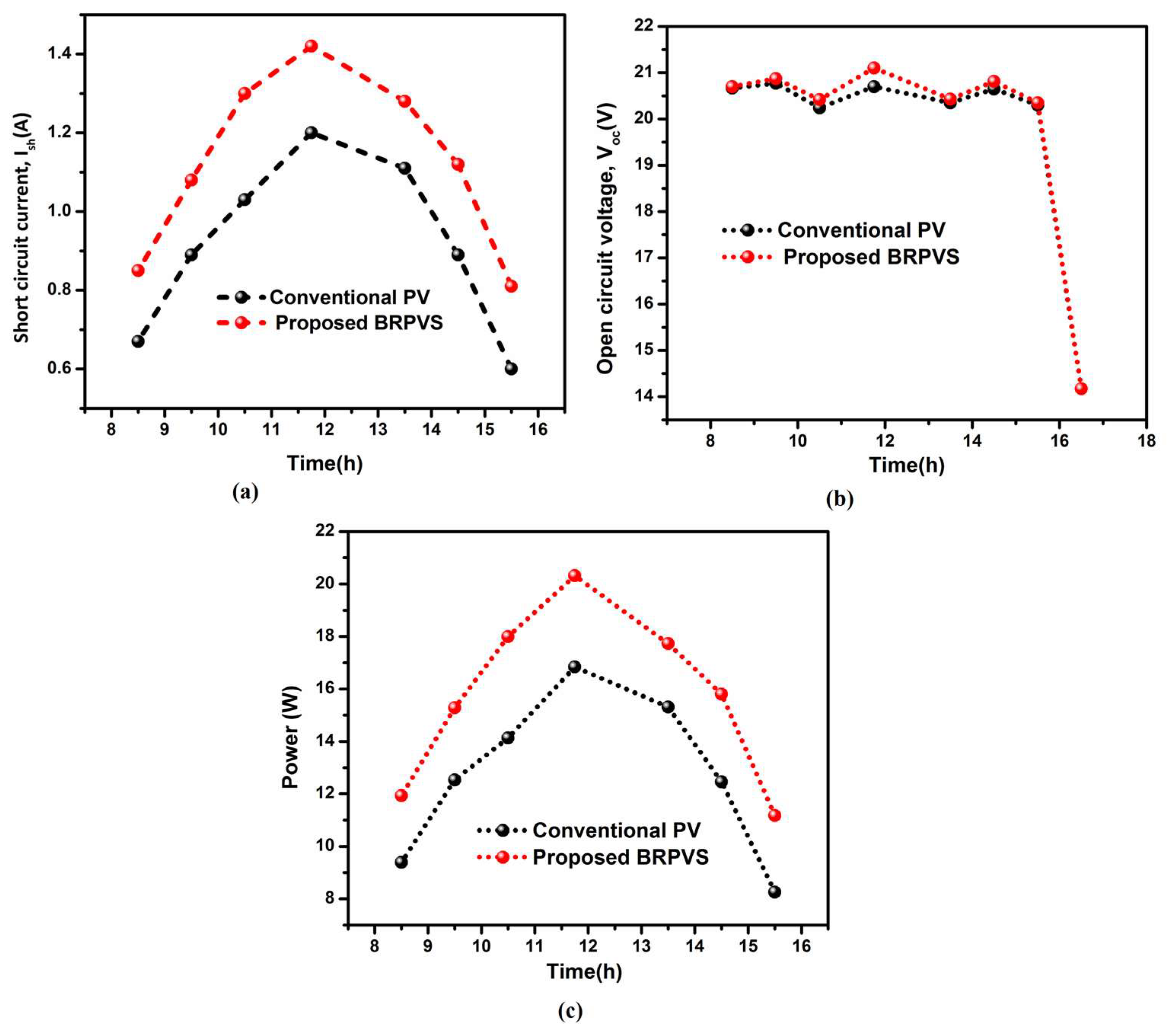
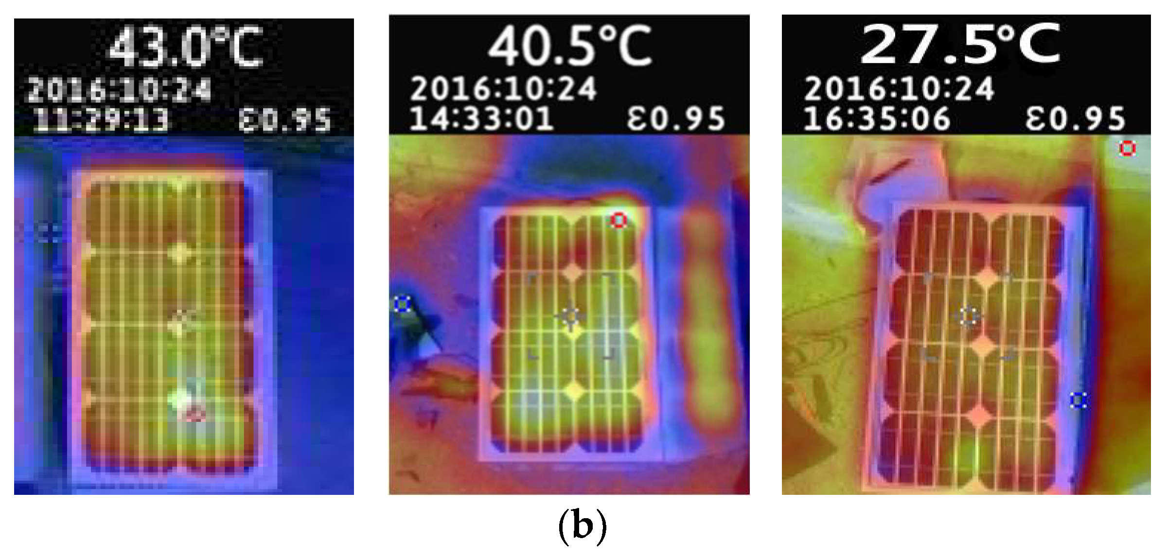
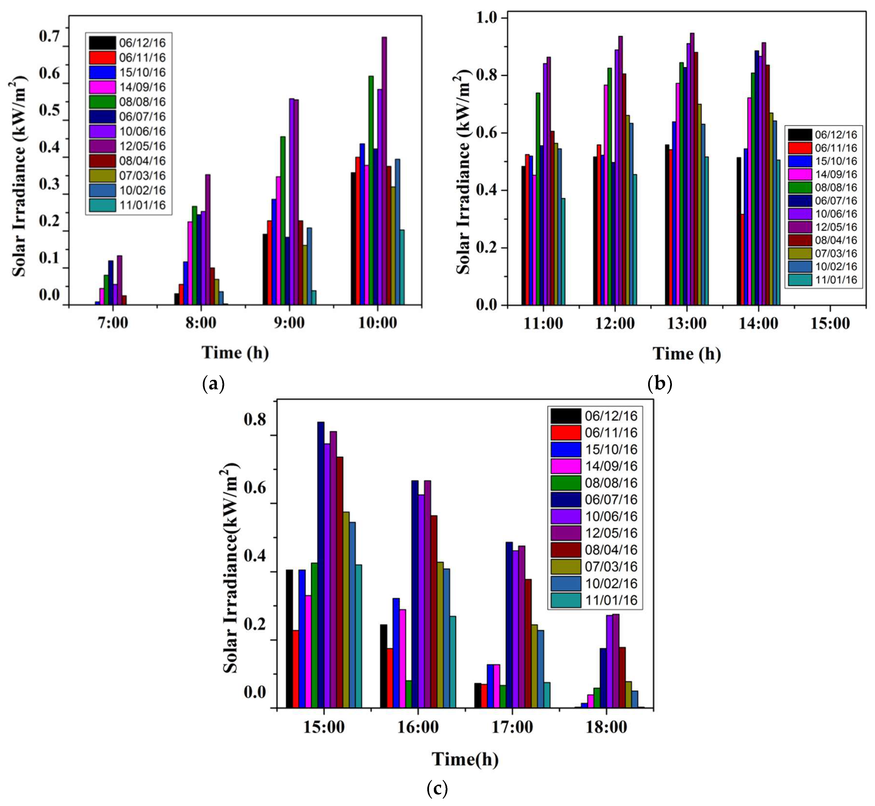
4.1. Investigating Effectiveness of BRPVS
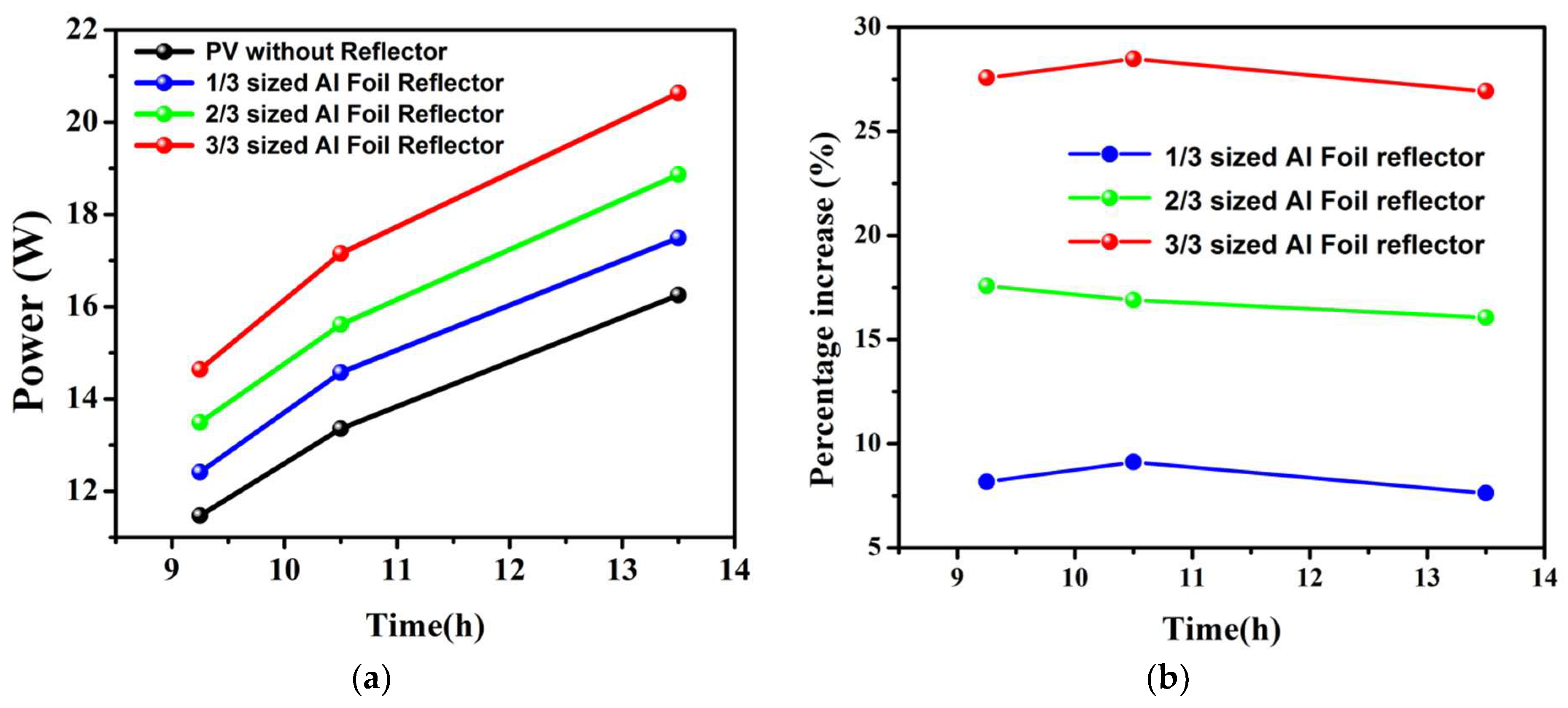
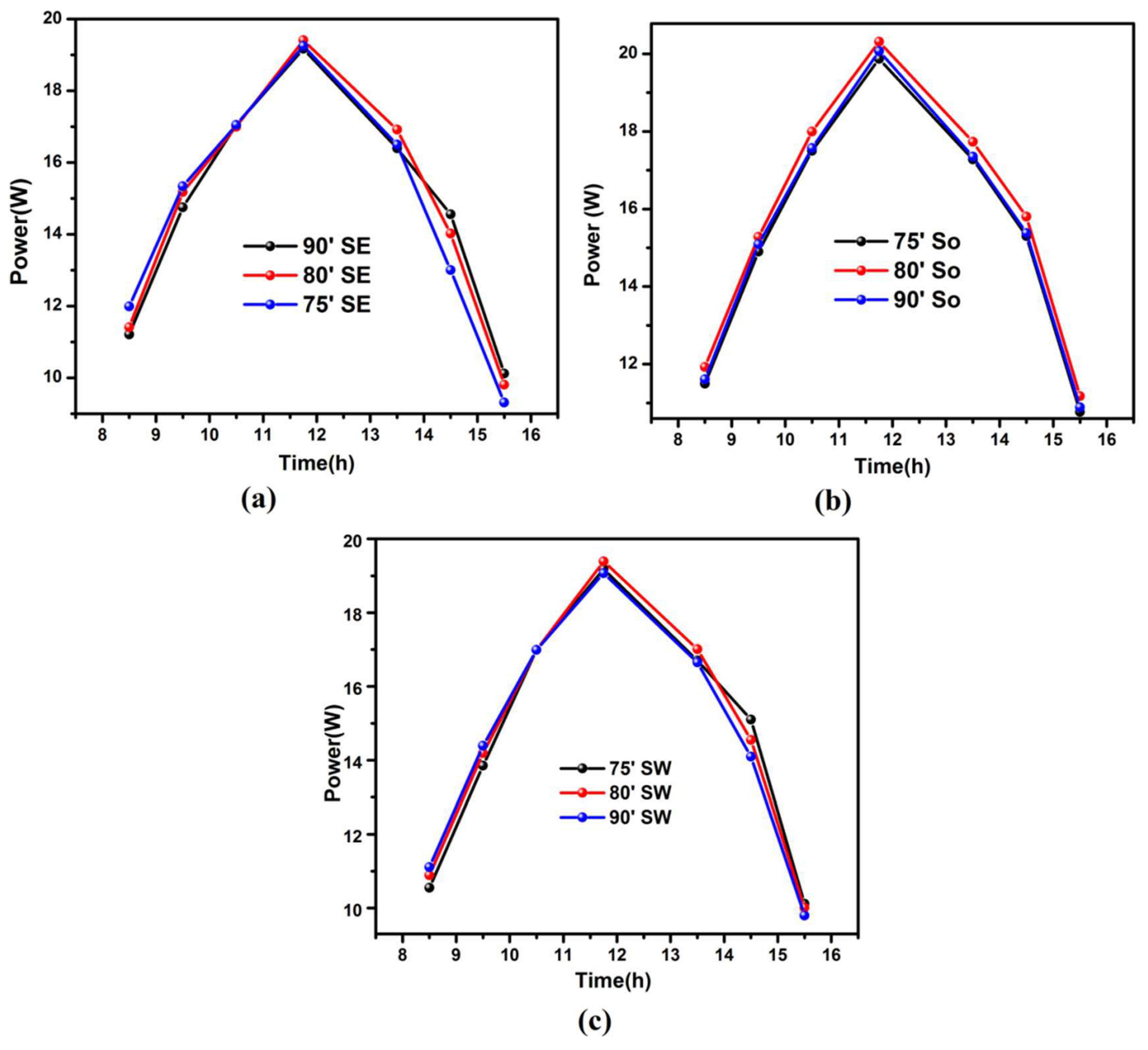
4.2. Al-Foil Reflector Optimal Size and Position for BRPVS
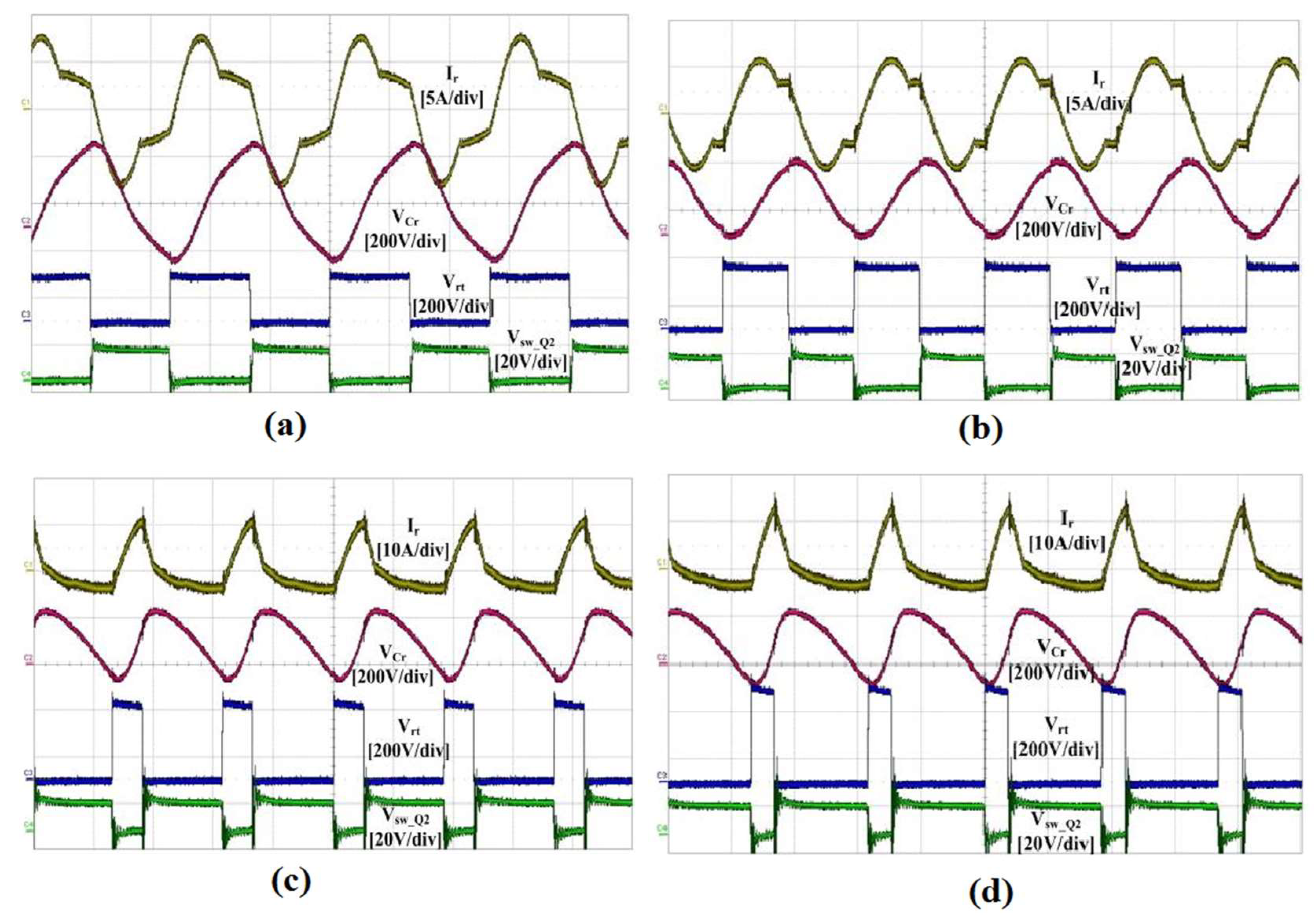
4.3. Performance Evaluation of Designed Half Bridge LLC Converter
5. Conclusions
Author Contributions
Acknowledgments
Conflicts of Interest
References
- Liu, X.; Wu, Y.; Hou, X.; Liu, H. Investigation of the Optical Performance of a Novel Planar Static PV Concentrator with Lambertian Rear Reflectors. Buildings 2017, 7, 88. [Google Scholar] [CrossRef]
- Tahir, S.; Wang, J.; Baloch, M.H.; Kaloi, G.S. Digital Control Techniques Based on Voltage Source Inverters in Renewable Energy Applications: A Review. Electronics 2018, 7, 18. [Google Scholar] [CrossRef]
- Norton, B.; Eames, P.C.; Mallick, T.K.; Huang, M.J.; McCormack, S.J.; Mondol, J.D.; Yohanis, Y.G. Enhancing the performance of building integrated photovoltaics. Sol. Energy 2011, 85, 1629–1664. [Google Scholar] [CrossRef] [Green Version]
- Öztürk, S.; Canver, M.; Çadırcı, I.; Ermiş, M. All SiC Grid-Connected PV Supply with HF Link MPPT Converter: System Design Methodology and Development of a 20 kHz, 25 kVA Prototype. Electronics 2018, 7, 85. [Google Scholar] [CrossRef]
- Tian, H.; Yu, X.; Zhang, J.; Duan, W.; Tian, F.; Yu, T. The influence of environmental factors on DSSCs for BIPV. Int. J. Electrochem. Sci. 2012, 7, 4686–4691. [Google Scholar]
- Mousazadeh, H.; Keyhani, A.; Javadi, A.; Mobli, H.; Abrinia, K.; Sharifi, A. A review of principle and sun-tracking methods for maximizing solar systems output. Renew. Sustain. Energy Rev. 2009, 13, 1800–1818. [Google Scholar] [CrossRef]
- Yaden, M.F.; Melhaoui, M.; Gaamouche, R.; Hirech, K.; Baghaz, E.; Kassmi, K. Photovoltaic System Equipped with Digital Command Control and Acquisition. Electronics 2013, 2, 192–211. [Google Scholar] [CrossRef] [Green Version]
- Hafez, A.Z.; Yousef, A.M.; Harag, N.M. Solar tracking systems: Technologies and trackers drive types—A review. Renew. Sustain. Energy Rev. 2018, 91, 754–782. [Google Scholar] [CrossRef]
- Vračar, L.; Prijić, A.; Nešić, D.; Dević, S.; Prijić, Z. Photovoltaic Energy Harvesting Wireless Sensor Node for Telemetry Applications Optimized for Low Illumination Levels. Electronics 2016, 5, 26. [Google Scholar] [CrossRef]
- Khan, M.A.; Zeb, K.; Sathishkumar, P.; Ali, M.U.; Uddin, W.; Hussain, S.; Ishfaq, M.; Khan, I.; Cho, H.-G.; Kim, H.-J. A Novel Supercapacitor/Lithium-Ion Hybrid Energy System with a Fuzzy Logic-Controlled Fast Charging and Intelligent Energy Management System. Electronics 2018, 7, 63. [Google Scholar] [CrossRef]
- Chemisana, D. Building integrated concentrating photovoltaics: A review. Renew. Sustain. Energy Rev. 2011, 15, 603–611. [Google Scholar] [CrossRef]
- Yoon, S.; Tak, S.; Kim, J.; Jun, Y.; Kang, K.; Park, J. Application of transparent dye-sensitized solar cells to building integrated photovoltaic systems. Build. Environ. 2011, 46, 1899–1904. [Google Scholar] [CrossRef]
- French, R.H.; Murray, M.P.; Lin, W.C.; Shell, K.A.; Brown, S.A.; Schuetz, M.A.; Davis, R.J. Solar radiation durability of materials components and systems for low concentration photovoltaic systems. In Proceedings of the IEEE Energytech, Cleveland, OH, USA, 25–26 May 2011; pp. 1–5. [Google Scholar]
- Probst, M.M.; Roecker, C. Towards an improved architectural quality of building integrated solar thermal systems (BIST). Sol. Energy 2007, 81, 1104–1116. [Google Scholar] [CrossRef]
- Augustin, D.; Chacko, R.; Jacob, J. Canal top solar PV with reflectors. In Proceedings of the 2016 IEEE International Conference on Power Electronics, Drives and Energy Systems (PEDES), Trivandrum, India, 14–17 December 2016; pp. 1–5. [Google Scholar]
- Karlsson, B.; Wilson, G. MaReCo design for horizontal, vertical or tilted installation. In Proceedings of the EuroSun, Copenhagen, Denmark, 19–22 June 2000. [Google Scholar]
- Brogren, M.; Karlsson, B. Low-concentrating water-cooled PV thermal hybrid systems for high latitudes. In Proceedings of the Conference Record of the Twenty-Ninth IEEE Photovoltaic Specialists Conference, New Orleans, LA, USA, 19–24 May 2002; pp. 1733–1736. [Google Scholar]
- Dubey, S.; Tiwari, G.N. Thermal modeling of a combined system of photovoltaic thermal (PV/T) solar water heater. Sol. Energy 2008, 82, 602–612. [Google Scholar] [CrossRef]
- Anderson, T.N.; Duke, M.; Morrison, G.L.; Carson, J.K. Performance of a building integrated photovoltaic/thermal (BIPVT) solar collector. Sol. Energy 2009, 83, 445–455. [Google Scholar] [CrossRef] [Green Version]
- Baitule, A.S.; Sudhakar, K. Solar powered green campus: a simulation study. Int. J. Low-Carbon Technol. 2017, 12, 400–410. [Google Scholar] [CrossRef] [Green Version]
- Tien, N.X.; Shin, S. A Novel Concentrator Photovoltaic (CPV) System with the Improvement of Irradiance Uniformity and the Capturing of Diffuse Solar Radiation. Appl. Sci. 2016, 6, 251. [Google Scholar] [CrossRef]
- Pérez-Higueras, P.; Muñoz, E.; Almonacid, G.; Vidal, P.G. High concentrator photovoltaics efficiencies: Present status and forecast. Renew. Sustain. Energy Rev. 2011, 15, 1810–1815. [Google Scholar] [CrossRef]
- Kosti, L.T.; Pavlovi, Z.T. Optimal position of flat plate reflectors of solar thermal collector. Energy Build. 2012, 45, 161–168. [Google Scholar] [CrossRef]
- Pucar, M.D.J.; Despic, A.R. The enhancement of energy gain of solar collectors and photovoltaic panels by the reflection of solar beams. Energy 2002, 27, 205–223. [Google Scholar] [CrossRef]
- Hall, M.; Roos, A.; Karlsson, B. Reflector materials for two-dimensional low-concentrating photovoltaic systems: The effect of specular versus diffuse reflectance on the module efficiency. Prog. Photovolt. Res. Appl. 2005, 13, 217–233. [Google Scholar] [CrossRef]
- Grassie, S.L.; Sheridan, N.R. The use of planar reflectors for increasing the energy yield of flat-plate collectors. Sol. Energy 1977, 19, 663–668. [Google Scholar] [CrossRef]
- Tina, G.M.; Ventura, C. Energy assessment of enhanced fixed low concentration photovoltaic systems. Sol. Energy 2015, 119, 68–82. [Google Scholar] [CrossRef]
- Lin, W.C.; Hollingshead, D.; French, R.H.; Shell, K.A.; Schuetz, M.; Karas, J. Non-tracked mirror-augmented photovoltaic design and performance. In Proceedings of the 38th IEEE Photovoltaic Specialists Conference (PVSC), Austin, TX, USA, 3–8 June 2012; pp. 2076–2081. [Google Scholar]
- Van Dijk, L.; van de Groep, J.; Veldhuizen, L.W.; Di Vece, M.; Schropp, R.E.I. Concepts for external light trapping and its utilization in colored and image displaying photovoltaic modules. Prog. Photovolt. Res. Appl. 2017, 25, 553–568. [Google Scholar] [CrossRef]
- Matsushima, T.; Setaka, T.; Muroyama, S. Concentrating solar module with horizontal reflectors. Sol. Energy Mater. Sol. Cells 2003, 75, 603–612. [Google Scholar] [CrossRef]
- Khan, M.A.; Ko, B.; Alois Nyari, E.; Park, S.E.; Kim, H.-J. Performance Evaluation of Photovoltaic Solar System with Different Cooling Methods and a Bi-Reflector PV System (BRPVS): An Experimental Study and Comparative Analysis. Energies 2017, 10, 826. [Google Scholar] [CrossRef]
- Filippini, M.; Molinas, M.; Oregi, E.O. A Flexible Power Electronics Configuration for Coupling Renewable Energy Sources. Electronics 2015, 4, 283–302. [Google Scholar] [CrossRef] [Green Version]
- Sathishkumar, P.; Krishna, T.N.V.; Himanshu; Khan, M.A.; Zeb, K.; Kim, H.-J. Digital Soft Start Implementation for Minimizing Start Up Transients in High Power DAB-IBDC Converter. Energies 2018, 11, 956. [Google Scholar] [CrossRef]
- Khan, M.A.; Krishna, T.N.V.; Sathishkumar, P.; Sarat, G.; Kim, H.-J. A hybrid power supply with fuzzy controlled fast charging strategy for mobile robots. In Proceedings of the International Conference on Information and Communication Technology Robotics (ICT-ROBOT 2016), Busan, Korea, 7–9 September 2016. [Google Scholar]
- Khan, M.A.; Badshah, S. Design and analysis of cross flow turbine for micro hydro power application using sewerage water. RJASET 2014, 8, 821–828. [Google Scholar] [CrossRef]
- Popavath, L.N.; Kaliannan, P. Photovoltaic-STATCOM with Low Voltage Ride through Strategy and Power Quality Enhancement in a Grid Integrated Wind-PV System. Electronics 2018, 7, 51. [Google Scholar] [CrossRef]
- Moonem, M.A.; Pechacek, C.L.; Hernandez, R.; Krishnaswami, H. Analysis of a Multilevel Dual Active Bridge (ML-DAB) DC-DC Converter Using Symmetric Modulation. Electronics 2015, 4, 239–260. [Google Scholar] [CrossRef] [Green Version]
- Buccella, C.; Cecati, C.; Latafat, H.; Razi, K. A grid-connected PV system with LLC resonant DC-DC converter. In Proceedings of the International Conference on Clean Electrical Power (ICCEP), Alghero, Italy, 11–13 June 2013. [Google Scholar]
- Beiranvand, R.; Rashidian, B.; Zolghadri, M.R.; Alavi, S.M.H. Using LLC resonant converter for designing wide-range voltage source. IEEE Trans. Ind. Electron. 2011, 58, 1746–1756. [Google Scholar] [CrossRef]
- Chang, C.H.; Chang, E.C.; Cheng, H.L. A high-efficiency solar array simulator implemented by an LLC resonant DC–DC converter. IEEE Trans. Ind. Electron. 2013, 28, 3039–3046. [Google Scholar] [CrossRef]
- Mishima, T.; Nakaoka, M. A novel high-frequency transformer-linked soft-switching half-bridge DC–DC converter with constant-frequency asymmetrical PWM scheme. IEEE Trans. Ind. Electron. 2009, 56, 2961–2969. [Google Scholar] [CrossRef]
- Jang, J.; Pidaparthy, S.K.; Choi, B. Current Mode Control for LLC Series Resonant DC-to-DC Converters. Energies 2015, 8, 6098–6113. [Google Scholar] [CrossRef] [Green Version]
- Shin, D.; Lee, K.J.; Lee, J.P.; Kim, H.J. Hybrid Control Scheme for a Half-Bridge LLC Resonant Converter with a Wide Input Range. In Proceedings of the International Conference on Intelligent Robotics and Applications, Busan, Korea, 25–28 September 2013; pp. 345–352. [Google Scholar]
- Feng, W.; Lee, F.C.; Mattavelli, P. A hybrid strategy with simplified optimal trajectory control for LLC resonant converters. In Proceedings of the Twenty-Seventh Annual IEEE Applied Power Electronics Conference and Exposition (APEC), Orlando, FL, USA, 5–9 February 2012; pp. 1096–1103. [Google Scholar]
- The Facets about Aluminum. Available online: http://www.alufoil.org/facts.html (accessed on 24 July 2017).
- Stutenbaeumer, U.; Mesfin, B. Equivalent model of monocrystalline, polycrystalline and amorphous silicon solar cells. Renew. Energy 1999, 18, 501–512. [Google Scholar] [CrossRef]
- Bahaidarah, H.M.; Tanweer, B.; Gandhidasan, P.; Rehman, S. A Combined optical, thermal and electrical performance study of a V-trough PV System—Experimental and analytical investigations. Energies 2015, 8, 2803–2827. [Google Scholar] [CrossRef]
- Andrews, R.W.; Pollard, A.; Pearce, J.P. Photovoltaic system performance enhancement with nontracking planar concentrators: Experimental results and bidirectional reflectance function (BDRF)-based modeling. In Proceedings of the IEEE 39th Photovoltaic Specialists Conference (PVSC), Tampa, FL, USA, 16–21 June 2013; pp. 229–234. [Google Scholar]
- Khan, M.A.; Zeb, K.; Sathishkumar, P.; Himanshu; Rao, S.S.; Gopi, C.V.V.M.; Kim, H.-J. A Novel Off-Grid Optimal Hybrid Energy System for Rural Electrification of Tanzania Using a Closed Loop Cooled Solar System. Energies 2018, 11, 905. [Google Scholar] [CrossRef]


| Density | 2.7 g/cm³ |
| Melting point | 660 °C |
| Al foil specific weight | 6.35 µm foil weighs 17.2 g/m2 |
| Melting point | 660 °C |
| Electrical resistivity | 26.5 nΩm |
| Electrical conductivity | 64.94% IACS (IACS: International Annealed Copper Standard) |
| Thermal conductivity | 235 W/m·K |
| Thickness | Foil is defined as measuring less than 0.2mm (<200 µm) |
| At short circuit | |
| At open circuit voltage | I = 0, V = Voc,ref |
| At short circuit current | I = Isc,ref, V = 0 |
| At the maximum power point | I = Imp,ref, V = Vmp,ref |
| At the maximum power point |
| Parameter | Value |
|---|---|
| Maximum Power () | 400 W |
| Switching Frequency () | 60–112 kHz |
| Input voltage range () | 200–400 V |
| Series Resonant Capacitance () | 66 nF |
| Output voltage () | 48 V |
| Series Resonant Inductance () | 30.56 μH |
| Parallel Resonant Inductance () | 103.44 μH |
| Turn Ratio of Transformer ( | 24:7 |
| Input Capacitance ( | 450 V/330 μF |
| Output Capacitance ( | 200 V/220 μF |
© 2018 by the authors. Licensee MDPI, Basel, Switzerland. This article is an open access article distributed under the terms and conditions of the Creative Commons Attribution (CC BY) license (http://creativecommons.org/licenses/by/4.0/).
Share and Cite
Khan, M.A.; Zeb, K.; Uddin, W.; Sathishkumar, P.; Ali, M.U.; Hussain, S.; Ishfaq, M.; Himanshu; Subramanian, A.; Kim, H.-J. Design of a Building-Integrated Photovoltaic System with a Novel Bi-Reflector PV System (BRPVS) and Optimal Control Mechanism: An Experimental Study. Electronics 2018, 7, 119. https://doi.org/10.3390/electronics7070119
Khan MA, Zeb K, Uddin W, Sathishkumar P, Ali MU, Hussain S, Ishfaq M, Himanshu, Subramanian A, Kim H-J. Design of a Building-Integrated Photovoltaic System with a Novel Bi-Reflector PV System (BRPVS) and Optimal Control Mechanism: An Experimental Study. Electronics. 2018; 7(7):119. https://doi.org/10.3390/electronics7070119
Chicago/Turabian StyleKhan, Muhammad Adil, Kamran Zeb, Waqar Uddin, P. Sathishkumar, Muhammad Umair Ali, S. Hussain, M. Ishfaq, Himanshu, Archana Subramanian, and Hee-Je Kim. 2018. "Design of a Building-Integrated Photovoltaic System with a Novel Bi-Reflector PV System (BRPVS) and Optimal Control Mechanism: An Experimental Study" Electronics 7, no. 7: 119. https://doi.org/10.3390/electronics7070119