1. Introduction
Full-scale testing of agricultural operations management can often prove both costly and time consuming, while computer simulations often make assumptions and estimates about the environment, sensors and actuators in the system. In particular, when considering agricultural operations, full-scale testing can only be carried out at certain times of the year, possible only a few months, and tests on the same area cannot be easily repeated, i.e., a crop can only be harvested once.
Computer models intended to simulate sensors and actuators are only a representation of reality with a certain level of accuracy. The models are designed to simulate scenarios the developers have deemed relevant to test design parameters. In [
1], GPS signals are simulated to realize the external noise sources affecting the operations of an agricultural vehicle’s auto-steering system. The GNSS and vehicle model are tested with a nonlinear model predictive controller. The current system models are still only designed to test the scenarios the developers want to research based on current domain knowledge.
Software tools for modeling and simulation of robot vehicles exist in the form of tools, such as player-stage-gazebo and Microsoft robotics studio. Game engines for physical simulation or model-based differential equations allow a robotics simulation tool to simulate the system physics [
2]. Robotics simulation frameworks have been used to move directly from simulation to full deployment on a vehicle. Robotics simulation frameworks provide a number of generalized building blocks (vehicle, sensors and actuators) that can be modified to describe different setups. To select viable solutions, extensive domain knowledge of the system type and tool building blocks is needed. The authors of [
3] first use computer simulation and then real life testing to gather results on the effectiveness of a system to control small robots during an environment discovery procedure. Simply procedural algorithms were tested in the computer simulation, and once their robustness was proven, real life testing was carried out on a small scale.
An intermediate step between simulation and deployment has been developed in recent years, by utilizing a Hardware-In-the-Loop [
4] test setup to evaluate an algorithm’s control response and robustness. A Hardware-In-the-Loop test setup is still dependent on the correct modeling of sensors and actuators, for evaluation of the control loop.
In the case of field machinery operations, whilst there are a number of examples for the implementation of test platforms and small-scale machines, these are limited. The authors of [
5] used two iRobot Magellan Pro robots in an indoor environment in order to demonstrate a methodology for real-time docking of combined harvesters and transport carts. The authors of [
6] used the iRobot platform to test a swarm intelligence algorithmic approach for multi-robot setup for controlling weed patches distributed within a field area, and [
7] developed a robotic platform equipped with cameras for row guidance and weed detection for the mapping of weed populations in fields, which was used to demonstrate intelligent concepts for autonomous vehicles.
Nevertheless, the above-mentioned examples are customized tools developed specifically for each application under study and do not build in a common standard framework.
LEGO Mindstorms is an example of a common framework that has been used in other scientific disciplines related to robotics, e.g., robotic exploitation [
8] and team intelligence [
9]. LEGO Mindstorms provides a proven, versatile framework for prototyping mechanical robotic systems that are programmed with a high degree of complexity. It also provides a system that has the ability to add and remove functionalities, as well as to reconfigure its architecture. This allows it to adapt to the needs of the different requirements of various applications, giving it an advantage over other frameworks. This critical notion is in accordance with the requirements of future innovative agricultural fleet management systems, as have been outlined [
10].
In order to quickly test operational management techniques, a test platform was developed, utilizing a LEGO Mindstorms micro-tractor, allowing for easily replicable results that can be evaluated while interpreting collected data. The test platform also consists of control and display modules that enable it to execute and monitor management techniques. Compared to a Hardware-In-the-Loop, solution the micro-tractor allows for the evaluation of software components using actual sensory input. This test platform is seen as an intermediate between simulation and full-scale testing, rather than a replacement of either.
In this paper, the test platform is described in terms of its hardware and software components. The performance of the platform is demonstrated and tested in terms of its capability of supporting decision making on field operation planning by indoor environment simulations. Following this introduction, the LEGO Mindstorms suite is described in
Section 2. In
Section 3, the hardware and the software components are described.
Section 4 outlines the tests, which were conducted to prove the test platforms’ fitness for the purpose, and finally, conclusions are made in
Section 5.
2. The LEGO Mindstorms NXT
LEGO Mindstorms is a suite developed by LEGO containing the “NXT Intelligent Brick” as the main controlling unit. It is programmed either using LEGO’s own Mindstorms IDE (integrated development environment) or various third-party development tools. The NXT Brick is capable of controlling three LEGO NXT servo motors in terms of rotation speed and direction, via voltage regulation. The NXT servo motors also have built-in rotary encoders that can deliver 720 steps, equivalent to an accuracy of 0.5°, which are used to monitor the angular position respective to their starting position, which is deemed to be zero degrees. The NXT Brick can have up to four sensors as inputs through either analogue or I2C connections. These sensors include standard LEGO sensors, such as light sensors, touch sensors and ultra-sonic sensors, and sensors developed from other companies (e.g., ViTech, Microinfinity, Dexter Industries), such as temperature sensors, color sensors, chemical sensors, etc., coping with the measuring requirements of scientific experimentations.
3. Methods
3.1. Hardware
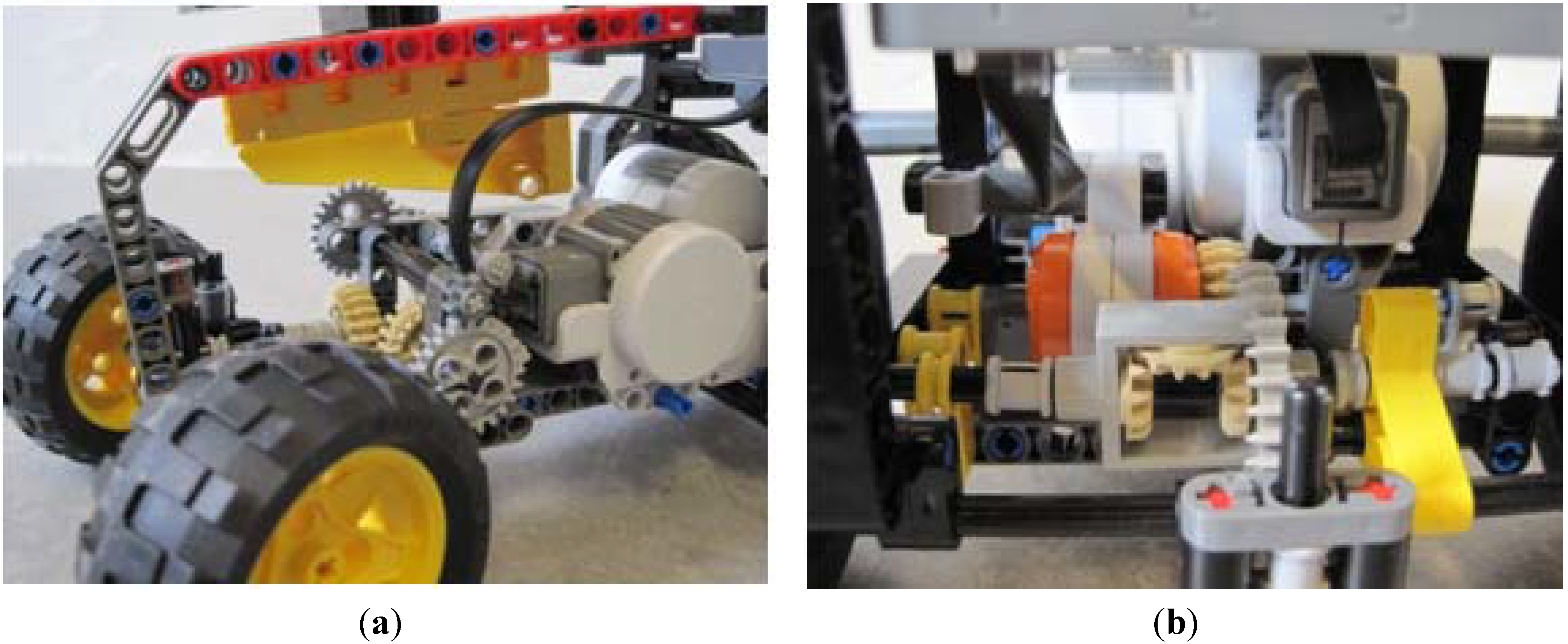
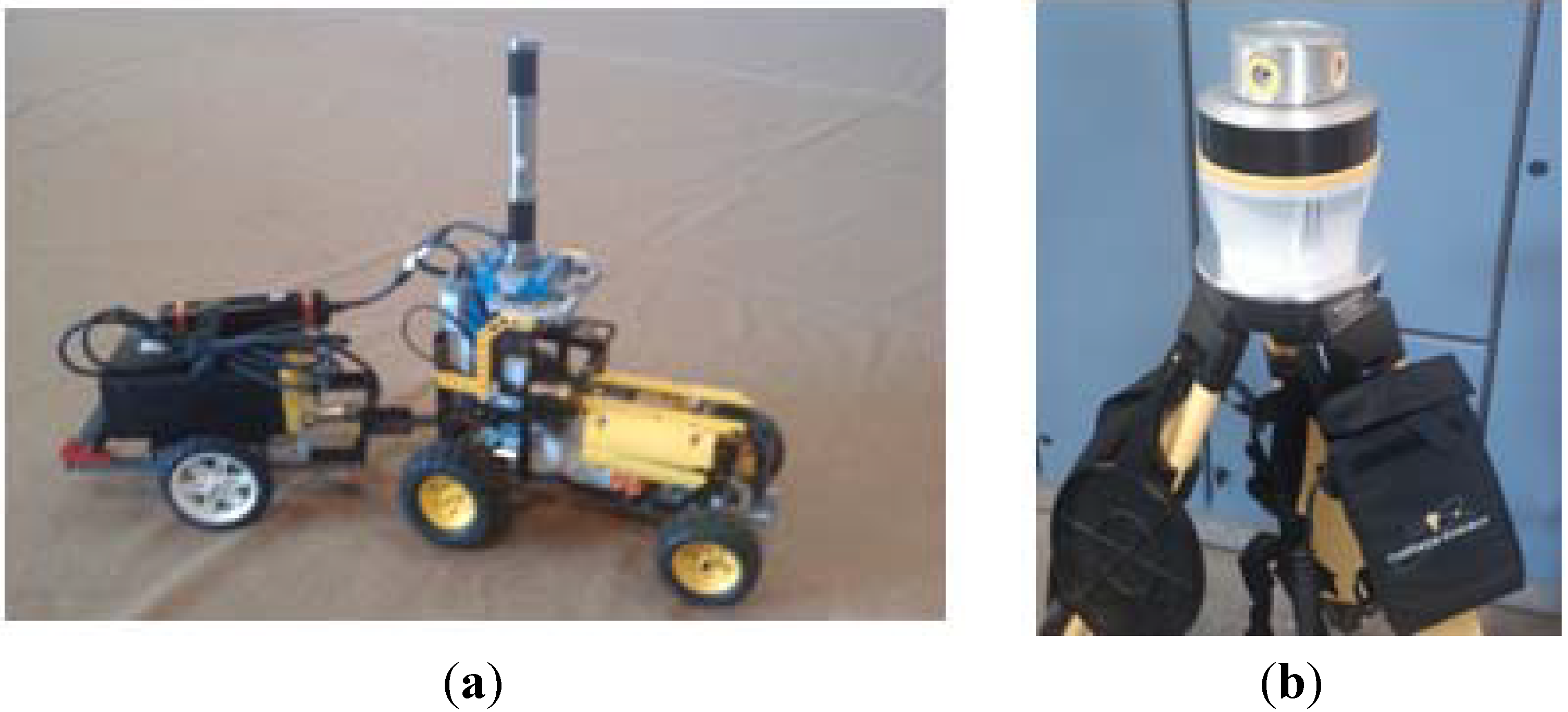
The steering of the tractor is actuated with a rack and pinion system, which allows the front wheels to turn through ±30°. A standard NXT motor was used to control the steering (
Figure 1a) with a gearing at a ratio of 7:1 to increase the range of the control. The rear wheels are controlled by another NXT motor (
Figure 1b), which transmits the power to the back axles via a differential gear. This allows the vehicle to turn corners without the back wheels slipping. The specific relation of the gearing ratio and the size of the rear wheels tires results in a 0.51 mm movement of the tractor for each degree that the drive motor turns.
The micro-tractor was designed to be a representation of a generic tractor, rather than a specific tractor, so as to allow more flexibility in the transferability of the results. The micro-tractor has a wheelbase of 175 mm and a turning radius of 370 mm. Considering that an average medium-sized tractor (150 hp) has a wheelbase and turn radius of approximately 2.5 m and 5.2 m, this would correspond to a scaling of 1:14. If there is a need for the test result to demonstrate a specific tractor, the use of LEGO would allow for fast modification.
Figure 1.
Photos of the steering and drive components.
Figure 1.
Photos of the steering and drive components.
The main navigation sensor is the CruizCore® XG1300L IMU, which is mounted on the front of the micro-tractor and is able to measure the relative heading of the micro-tractor compared to the starting position with a relative accuracy stated as <0.1°. The device contains a single axis MEMS gyroscope and a three-axis accelerometer. The signals from these sensors are processed onboard the device, applying factory set compensation factors, which helps to reduce the most significant errors. The measured heading is susceptible to a maximum error of 10°, according to the product specifications, during one hour of continuous operation.
As part of developing a platform to demonstrate various agricultural operations, implements can be constructed using additional NXT units. However, the micro-tractor has one motor port and three sensor ports available for implements that are not equipped with an NXT unit. The micro-tractor is equipped with a drawbar suitable for connecting implements.
3.2. Software
The BricxCC (Bricx Command Center), an open source Windows program that uses the NXC programming language [
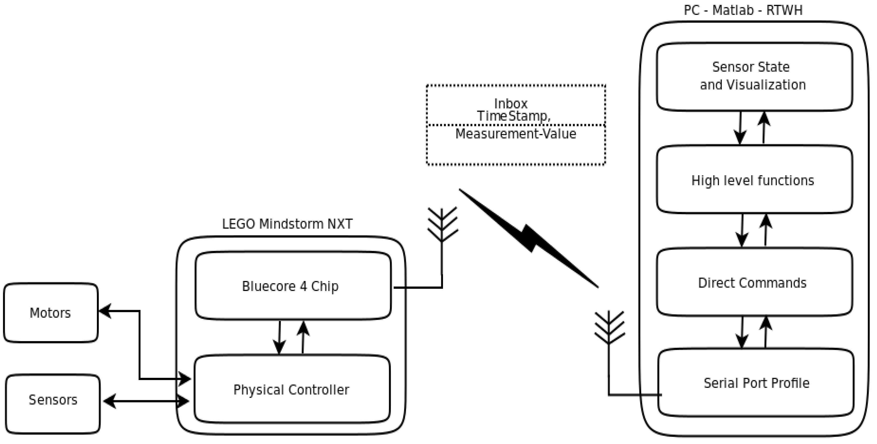
11], is used to compile the programs contained on the NXT Brick. Matlab (MathWorks
®) and the RWTH-Mindstorms NXT toolbox [
12] were used for remote communication with the NXT Brick via Bluetooth (
Figure 2).
Figure 2.
The communication architecture.
Figure 2.
The communication architecture.
3.2.1. Communication
The Bluetooth protocol utilized by LEGO is placed on top of the Serial Port Profile (SPP) protocol. Direct control commands provide the ability to remote control the NXT from a computer. Each NXT command over a Bluetooth connection takes approximately 100 ms to successfully process, making it too slow for precision control of the tractor. As a consequence, the micro-tractor was chosen to be programmed in the NXC programming language, and the compiled code was loaded directly onto the NXT for execution. Programming the NXT directly provides the ability to control the position and angle with a much higher accuracy, compared to the Bluetooth solution. If communication between the computer and brick is lost at any point during the testing, the NXT makes a sound, so that testing can be aborted and restarted.
3.2.2. Route Planning
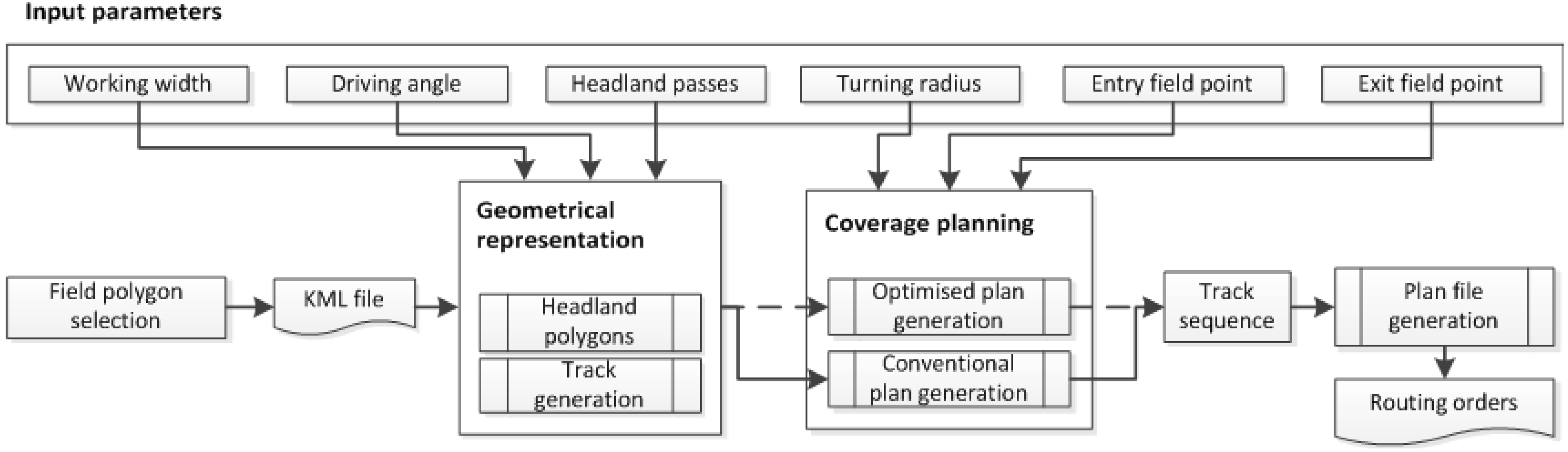
The route planning for the micro-tractor was implemented offline using the Matlab programming language. The input for planning includes the boundaries of the working area, which can be selected in a digital map, and a number of operational parameters (
Figure 3). Based on the input, as the first step, the geometrical representation of the field is generated. The geometrical representation regards the definition, in terms of their coordinates, of the geometrical entities inherent in a field area representation. These entities include the parallel field-work tracks and the peripheral boundary passes (headland area). The next step includes a coverage path generation, which could be either a conventional plan (e.g., sequential ordering of the tracks) or optimized according to the principle of
B-patterns, that algorithmically results in an optimal field-work track traversal sequence according to an optimization criterion [
13,
14]. In the latter case, the coverage plan does not follow the repetition of standard motifs, but the plan is a unique result of the optimization approach on the specific combination of the mobile unit kinematics, the operating width and the optimization criterion, such as, total or non-working travelled distance, total or non-productive operational time, a soil compaction measure [
15],
etc. In the presented case, the non-working travelled distance has been considered as the minimization criterion. The optimization problem is that of finding the optimal track sequence:
![Robotics 02 00203 i001]()
, where
T ={1,2,3,…} is the arbitrarily ordered set of the field tracks that cover the entire field area, σ =<
p‒1(1),
p‒1(2),…,
p‒1(│
T│) > is a permutation,
p(·) :
T →
T is the bijective function, which for any field track
i ϵ
T returns the position of the
ith field track in the track traversal sequence, and
![Robotics 02 00203 i002]()
is the cost for moving between tracks,
p‒1(
i + 1) and
p‒1(
i) , which, in the particular case, corresponds to the nonworking travelled distance.
Figure 3.
The architecture of the route planning.
Figure 3.
The architecture of the route planning.
The final function is the generation of the routing orders, which include a sequence of straight lines and turnings executions. Straight line segments are described by the heading, the distance to be travelled, the driving speed and the starting X and Y coordinates. Turning segments are described by the initial heading, the final heading, the direction of the turn (clockwise or anti-clockwise) and the driving speed.
3.2.3. Position Determination
The micro-tractor determines its position onboard the NXT using the heading value from the IMU and the encoder value from the drive motor. Using these values, the position and heading are calculated relative to the micro-tractor’s starting position and heading. While communicating with the visualization computer, the micro-tractor samples the IMU and drive motor encoder and calculates its position, at a rate of approximately 12 Hz. Using these techniques for position determination requires the micro-tractor to be operated on a face surface with minimal slip between the wheels and surface occurring.
3.2.4. Vehicle Navigation Control
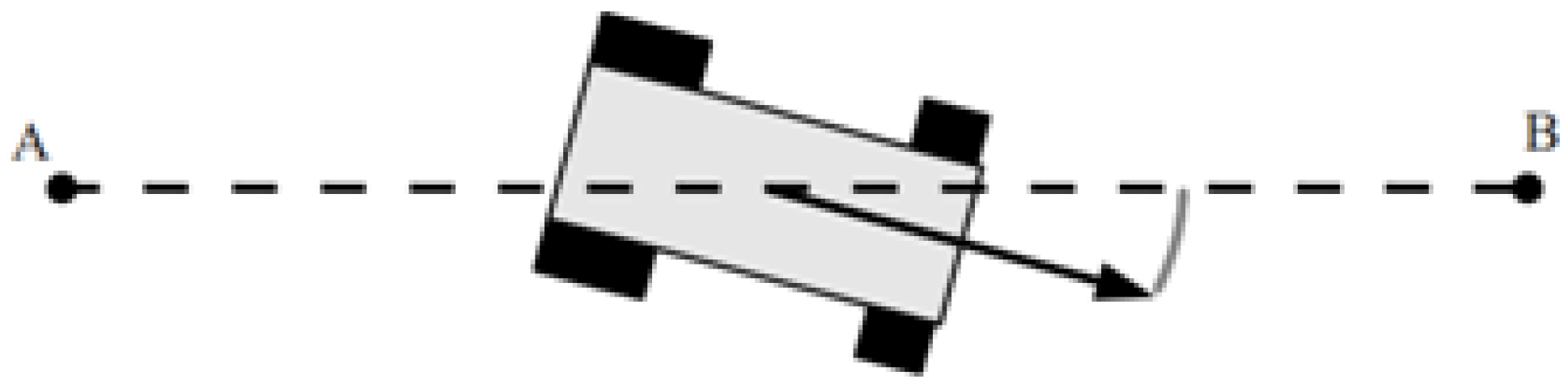
The route maintains its structure of a straight line and turning segments. The segment commands are passed to the NXT one at a time from the Matlab control system; this allows for the execution of management techniques that require real-time adaption of the route. During straight segments, the NXT calculates the number of revolutions of the drive motor it needs to make to drive the prescribed distance. While this is executing, the NXT monitors the micro-tractors distance from the line normal to the direction of travel and the angular error in the heading to that direction of travel (
Figure 4). These two calculated errors are entered into a transfer function, and the NXT makes an adjustment to the steering wheels in order for the micro-tractor to reduce these errors and follow the line as described. A similar control system is described in [
16] for use with a full-scale four-wheeled machine, where the errors are referred to as the lateral and angular error. The LEGO test platform also assumes that it is operating on a hard, flat surface with minimal slip. The parameters for the transfer function used were determined empirically.
Figure 4.
Heading error and distance from the line to travel.
Figure 4.
Heading error and distance from the line to travel.
To execute a turn segment, a second control function is used. The micro-tractor sets its wheel in a full lock position in the direction of the turn and then starts the drive motor. During the turn, the heading is monitored until the micro-tractor reaches its desired angle, at which point the drive motor is stopped and the steering wheels are turned back to the zero position. The reason the steering wheels are moved while the vehicle is stationary is to ensure that the micro-tractor traces perfect circles.
3.2.5. Visualization
The estimated current heading and position of the micro-tractor are written to a text string and passed into separate mailboxes with 100 ms division, overwriting the old message in the mailbox, along with a timestamp. The task of the Matlab system is to read the content of the mailbox and store and display the results. The current state of the tractor is then calculated and plotted on the map, the travelled path and the desired path are also plotted for comparison reasons.
3.3. Test Platform Architecture
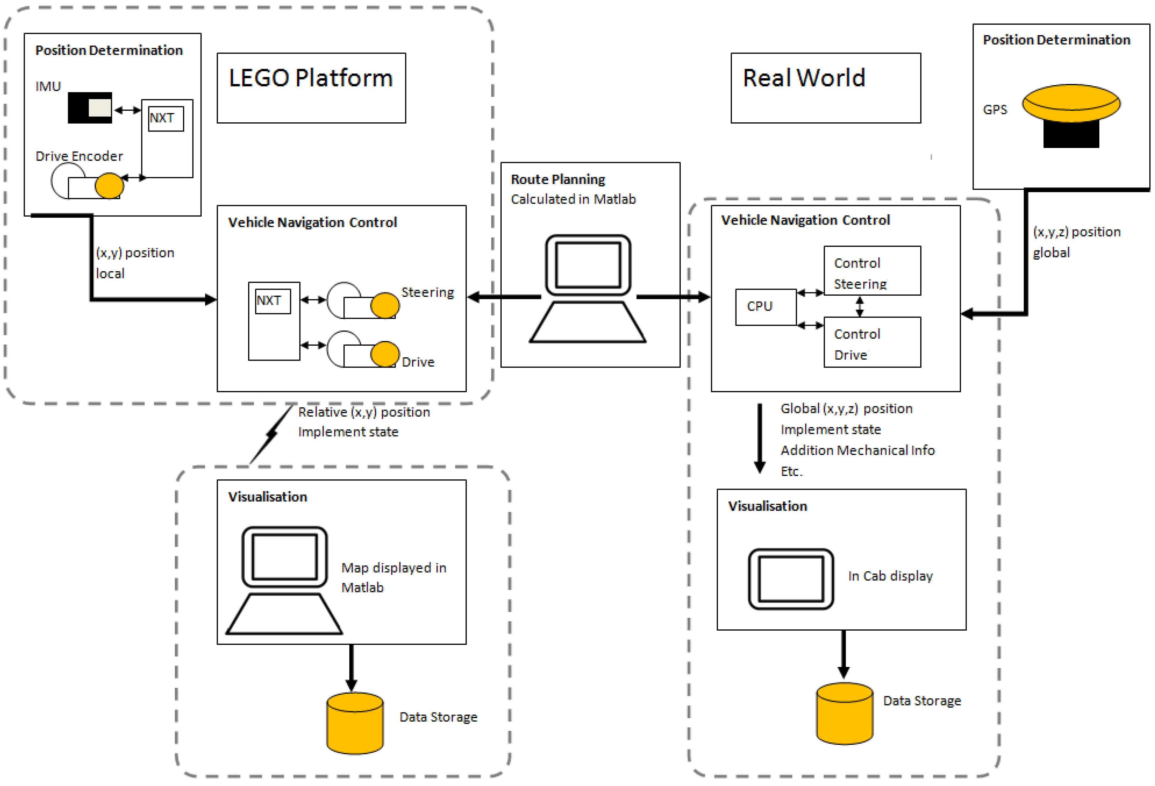
The architecture of the LEGO test platform aims at mimicking the real-world system in a meaningful way (
Figure 5). The main three modules of the system are the Position Determination, Vehicle Control and Visualization. Each of these modules is replicated within the test platform. Within the LEGO platform, although the Route Planning and Visualization are separate systems, they are run on the same computer. The dashed lines on
Figure 4 indicate the components of the system that contain the modules. There are some differences between the component setups in the systems; however, this does affect the functionality. For example, the connection between the Vehicle Control and Visualization modules is implemented via a wired connection in the real-world system and a wireless, Bluetooth connection in the LEGO platform. The functionality of these connections is simply to pass information from the Vehicle Control module to be displayed by the Visualization module. The rate at which this information is sent, approximately 10 Hz, is well within the tolerance of the Bluetooth connection; plus, as mentioned in
Section 3.2.1, if the connection is interrupted, the test is aborted. Therefore, the Bluetooth connection has the same functionality as the wired connection.
A similar full-scale testing system is described in [
17]. Route plans are first generated on a computer and transferred to the test tractor via USB. The tractor then executes the plan, while performing vehicle navigation, and displays the results on a small onboard computer. By using a similar architecture on the test platform as in the real world, the solutions that are found, such as route plans and management techniques, are able to be transferred to the real-world system more effectively.
Figure 5.
Depiction of LEGO platform and real-world architectures.
Figure 5.
Depiction of LEGO platform and real-world architectures.
The methods used in the Position Determination modules of the LEGO platform and the real world are vastly different; however, their outputs are the same. A limitation of the current Position Determination module in the LEGO platform is that the operation surface must be flat and provide minimal tire slip, which is not the case in the real world. A limitation of the real-world GPS system is the need for contact with many satellites, which can be susceptible to overhead obstructions, such as trees or cloud cover. Since the LEGO platform operates indoors, the use of a GPS system would be extremely difficult. In the real world, a combination of sensors, such as computer vision techniques or multiple GPS antennae, would be required to obtain an accurate estimate of the vehicle’s heading; however, in the LEGO platform, the IMU sensor is sufficient. In both systems, the Position Determination modules provide the Navigation Control module with an estimation of the current position and the current heading, so that steering corrections can be made, and in this way, they can be considered to be comparable.
The system architecture of the platform is built in a modular manner, so that components, such as the Navigation Control or Visualization, could be easily exchanged with another module, as long as the new module takes the same inputs and gives the same outputs. To increase the functionality of the system to allow for real-time operations management, the link between the Route Planning and Navigation Control modules should be modified to a two-way connection, so that data can flow between them. This connection would allow the Route Planning module to update the current plan due to any changes that may be observed. The micro-tractor can receive commands to execute each segment of the path separately; therefore, the remaining segments of the path, after the current segment, are still open to being altered. This modification of the architecture will be investigated in future work.
5. Conclusions
The proposed system represents the basic measures for developing a complete test platform for field operations, where route plans, mission plans, multiple-machinery cooperation strategies and machinery coordination can be simulated and tested in the laboratory. The laboratory tests are easy to demonstrate and replicate at any time of the year; full-scale testing is often limited by weather and field conditions. Furthermore, using a small-scale test platform eliminated a lot of the safety concerns associated with operating large driverless machinery. The test platform should be seen as an extension to simulations-based evaluation rather than a replacement. Even the most stringently programmed simulations are susceptible to errors or to things being overlooked. The test platform provides another stage of quality assurance, with systems interacting with real collected data, before full-scale testing is attempted. The results from the test platform also add credence when planning full-scale testing and eliminate costly, superfluous tests.
The proposed system also provides many opportunities as an educational tool. Students can quickly and easily test management techniques in a classroom environment and see their ideas implemented in a physical way. Moreover, the modular setup of the system architecture allows students to develop and test new modules, gaining many insights into system engineering and controller design. While the use of the IMU and encoder values adequately estimates the micro-tractors position, it limits the system, as the surface it is run on must be smooth, flat and solid. For the purposes of testing operational management techniques, this is of no consequence, as fields are often simplified using flat 2D representation. However, if another method for efficiently determining the micro-tractor position were deemed necessary, this module could be replaced without affecting the rest of the system.
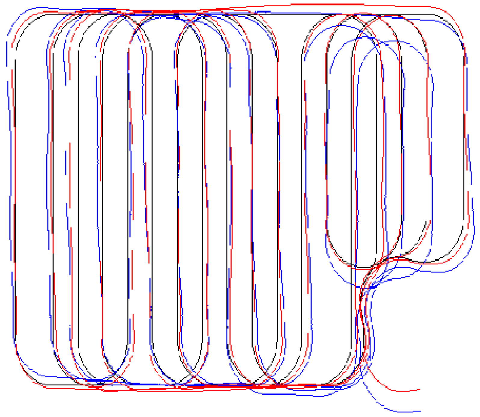
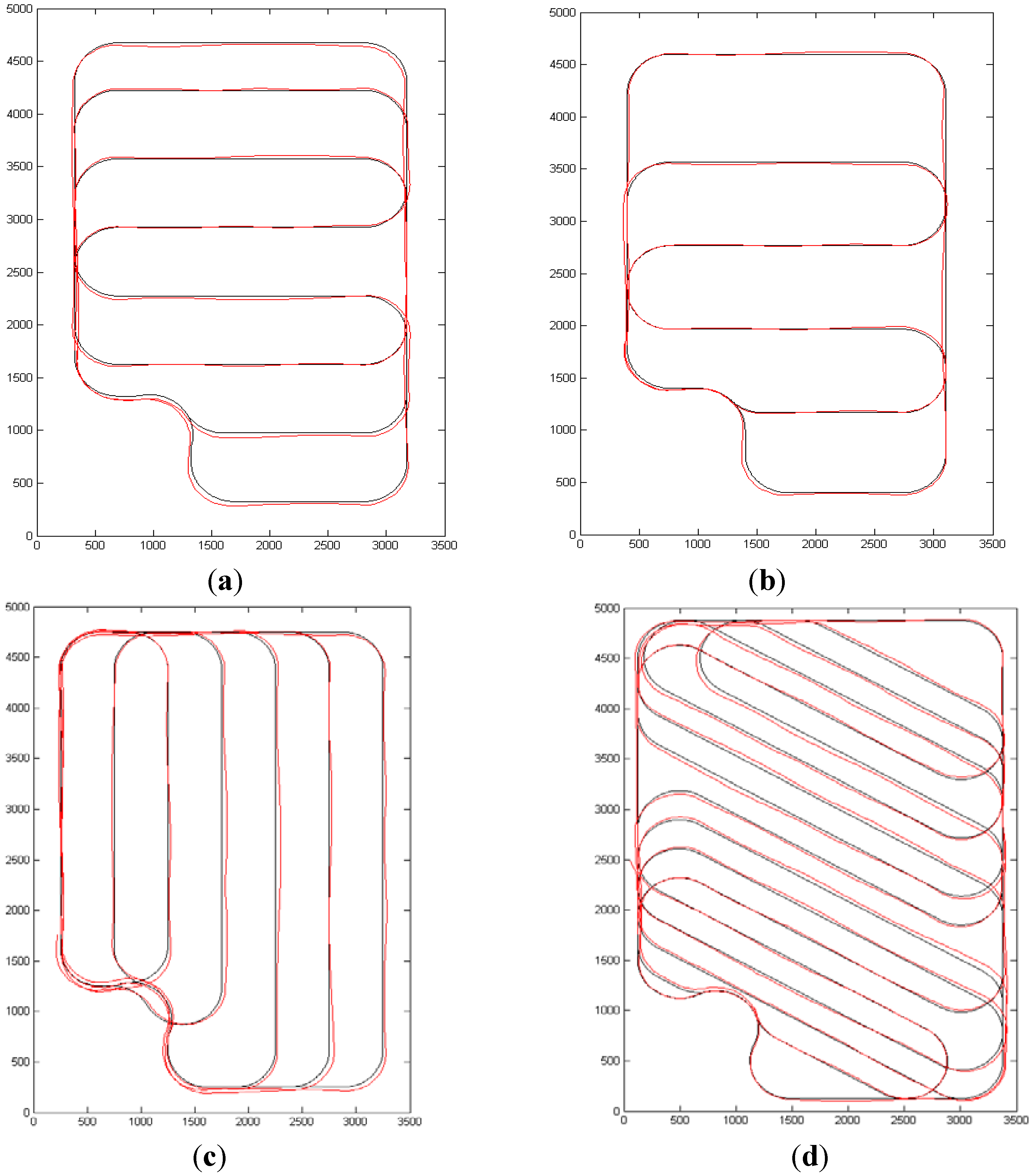
The execution of coverage plans was chosen to show the capabilities of the test platform to implement agricultural operations management techniques. The demonstration examples also show that is possible to evaluate coverage plan scenarios, involving different operational features (e.g., working widths, driving angles and number of headland passes), in terms of different operational efficiency measures, e.g., the measured non-working travelled distance, overlapped or missed area and operational time. The example using the real field (
Figure 9) could be used as the first step in developing a Control Traffic System for the real-world field. Since the route planning has been shown to be effective, the full-scale testing could proceed more quickly.
The next steps are envisioned to be, for example, the inclusion of additional sensors (e.g., for mapping spatial variations within an area, crop row following, collision detection and enhanced navigation accuracy) and the implementation of multiple micro-tractor systems.


 , where T ={1,2,3,…} is the arbitrarily ordered set of the field tracks that cover the entire field area, σ =< p‒1(1),p‒1(2),…,p‒1(│T│) > is a permutation, p(·) : T → T is the bijective function, which for any field track i ϵ T returns the position of the ith field track in the track traversal sequence, and
  is the cost for moving between tracks, p‒1(i + 1) and p‒1(i) , which, in the particular case, corresponds to the nonworking travelled distance.


