1. Introduction
Actuators with inherent compliance have been in development worldwide during the last decades with the goal of giving the advanced robots and/or rehabilitation devices a functionality which could not be found in traditional rigid robots. In general, inherent compliance of actuators can be achieved by using electromechanical drives in combination with elastic transmissions [
1] as well as by using actuators possessing natural inherent compliance such as pneumatic muscles [
2] or fluidic rotary elacstic chambers (REC) actuators [
3]. Due to their compliance, these actuators are very suitable to provide safe physical human–robot interaction, especially for rehabilitation applications. However, they include a fixed mechanical rotation axis and exoskeleton-like rehabilitation devices that require an exact adjustment to the individual human before the treatment. This procedure strongly reduces the effective treatment time in medical and rehabilitation centers.
To follow the polycentric movements of human joints, sophisticated mechanical structures are required [
4,
5]. These exoskeleton-like rehabilitation devices can indeed provide an exact adjustment to the individual human, but are not compliant and have high production costs. An implicit self-alignment (i.e., a proximate adjustment between the actuator and human joint movements) without complex mechanics, combined with a controllable stiffness/compliance can be achieved using multi-axial pneumatic soft-actuators [
6,
7]. This device is based on patented [
8] pneumatic skewed rotary elastic chambers (sREC). The next logical step was to remove the fixed mechanical axis. In doing so, the novel compliant pneumatic bending actuator has been developed, the so-called skewed rotary elastic chambers bending actuator (sRECBA). In contrast to intrinsically soft bending actuators as described in [
9], this kind of bending actuator is based on a combination of inherent compliant bellows (sREC) and rigid metal plates, which enables the provision of sufficient forces/torques to move the human’s extremities against gravity.
On the other hand, the sRECBA does not include any mechanical rotation axis and it is assumed that this compliant bending actuator can adjust itself to the polycentric motion of the human joint axis and thus provide for an implicit self-alignment to the human, which should increase the effective treatment time. A first prototype of an elbow trainer based on sRECBA is presented in [
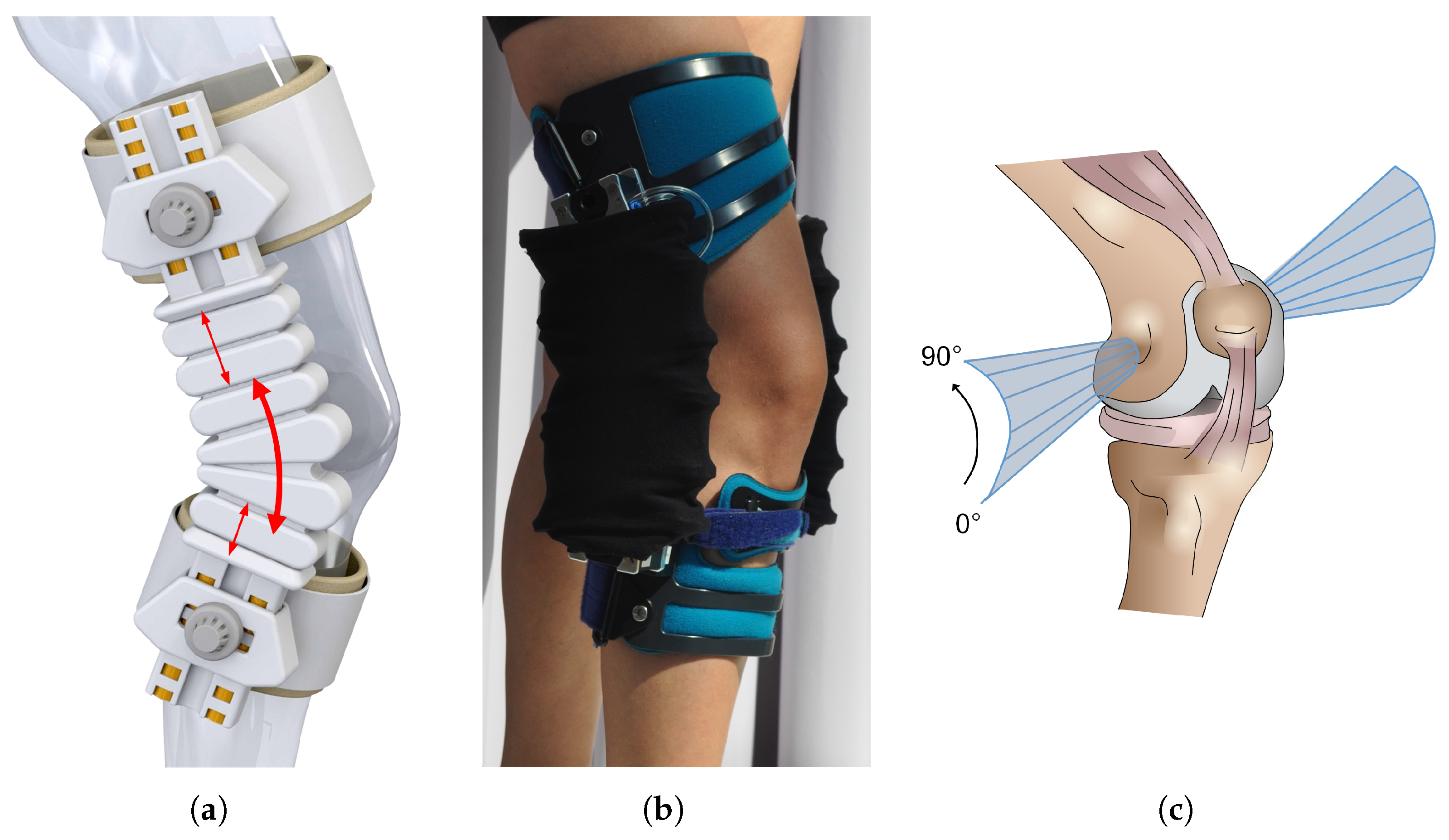
10]. As another possible realization example, an active knee orthesis (knee brace) is realized using the sRECBA, see
Figure 1. The conceptual design is shown in
Figure 1a and the first mock-up using a commercial passive knee brace (SecuTec
® Genu, Bauerfeind AG, Zeulenroda-Triebes, Germany) as a technical basis with the removed internal passive orthesis joints is shown in
Figure 1b.
To provide for an implicit self-alignment, knowledge about the motion capabilities of the sRECBA is of high interest. In contrast to intrinsically soft bending actuators, whose kinematics, as a subclass of continuum robots, can be generally described by a continuous function and whose behavior requires continuous mathematics in order to be modeled [
9], the kinematics of sRECBA can be described in a more simple manner.
The goal in this paper was to develop an equivalent kinematic model of the sRECBA in a simple, but sufficient and effective way, in order to investigate the motion of the actuator in simulation. It is shown in this paper that the kinematics of the sRECBA can be described using a series of four-bar linkages. To achieve this, at first, the finite helical axes (FHA) of basic actuator elements are determined and analyzed in an experimental manner. This specific axis of rotation is often used to describe the motion of an object in the three-dimensional space [
11,
12]. An illustration of FHA with respect to the knee flexion angle is presented in
Figure 1c. FHA are widely used in biomechanical applications, as they provide a description of joint motion independent of anatomical landmarks or cross talk effect—that is, misinterpreting the rotation of one axis as the rotation of another axis. Additionally, with FHA, the translational shift and the proportions of a rotational movement can be clearly visualized. The marker-based method proposed by Spoor and Veldpaus [
13] is used, based on data determined using a three-dimensional (3D) camera system. Afterwards, a simplified two-dimensional (2D) kinematic simulation model based on a four-bar linkage was developed and the resulting motion was compared to the experimental data by calculating the instantaneous center of rotation (ICR). The kinematic model of the sRECBA was developed using a series of four-bar linkages and the ICR was analyzed in simulation using different motion sequences. Finally, the FHA of the active knee orthesis based on sRECBA were determined and analyzed for three different specific motions.
Furthermore, the developed kinematic model is used to realize a mechanical reference sensor system, which will be used in the next step to develop a cost-effective position estimation system based on artificial neural networks (ANNs). The development of the signal processing algorithm is beyond the scope of this publication.
2. Compliant Pneumatic Bending Actuator with Skewed Rotary Elastic Chambers
The conceptual design of the developed sRECBA used for the application example of an active knee orthesis is presented in
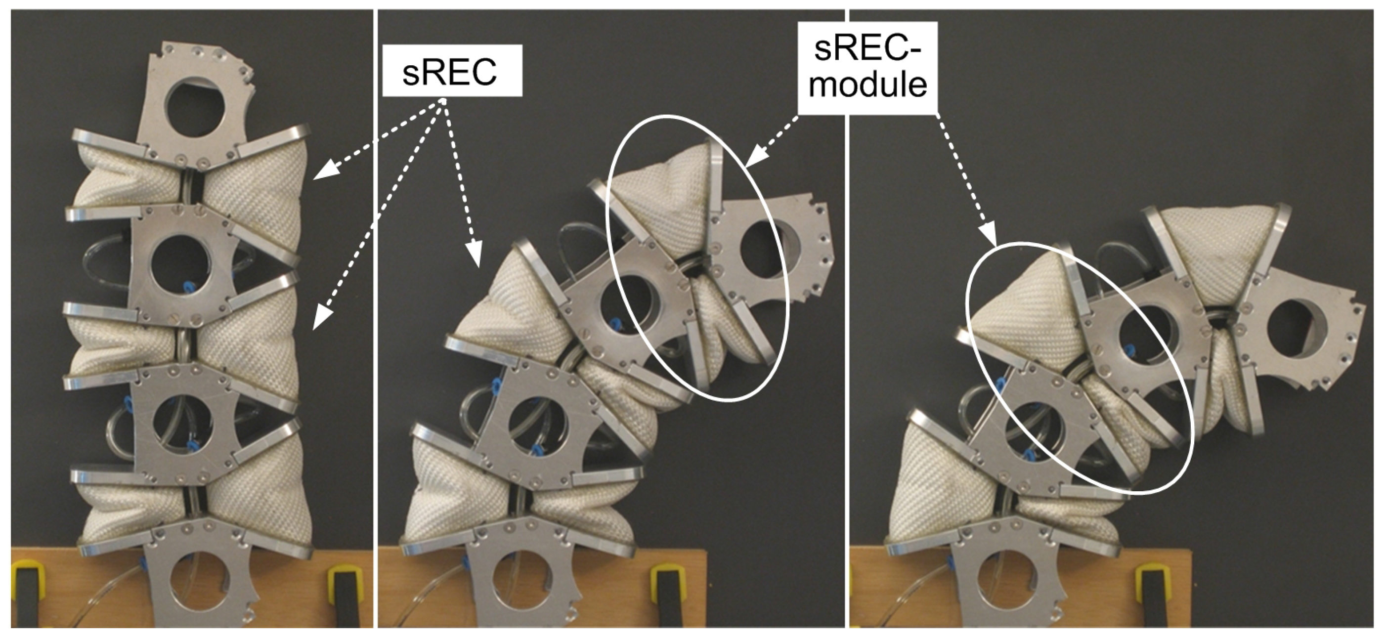
Figure 1a. The basic elements that are used for actuator development are self-made pneumatic bellows (sREC), see
Figure 2, that provide a direct rotational motion without any mechanical rotation axis. These patented actuator elements [
8] are manufactured using standard fire flat hose (Syntex Folia, Ohrdrufer SchlauchWeberei Eschbach GmbH, Ohrdruf, Germany) with low material costs—one meter costs about 2€. The hose is made of fabric with an inside coating of elastomers and is dimensioned for maximum pressures of 8 bar to 20 bar, so that high chamber reliability can be achieved. To realize bidirectional motion, two sRECs are mechanically connected antagonistically, resulting in a basic actuator element named as “sREC-module”, see
Figure 2. The stiffness of the actuator depends on the pressure provided in both actuator chambers. Finally, the actual realization of sRECBA is built as a series of three of these actuator modules. All bellows that are working in the same direction are pneumatically connected to achieve a bidirectional rotary movement with an overall moving range of almost 120°. Due to the asymmetric arrangement of the bellows, the moving range of the actuator is adjusted to the moving range of human joints, providing hard stops at moving range limits. Extension to more than 0° (i.e., stretching) is mechanically restricted to ensure the safety of human joints such as the knee and/or elbow.
Due to the construction, sufficient actuator forces/torques can be achieved—pressurized with 4 bar, the sRECBA can lift a load up to 8 kg in the flexion direction. This force level is sufficient to support a movement of human joints such as the elbow or knee during rehabilitation. In general, the developed force/torque is a nonlinear function of chamber pressure, angle and load condition. The investigation of these characteristics requires special test equipment which is in the planning stage. Because no common position sensors, such as incremental encoders that require a mechanical axis, can be used to determine the configuration of the sRECBA, inertial measurement units (IMUs) and flex sensors—as a “shaftless” measurement system that does not need mechanical axes—were tested and compared for use as possible sensors, see [
10]. It could be shown that for rehabilitation application, the use of cost-effective flex sensors in combination with ANNs, to compensate for nonlinearities and hysteresis effects, is sufficient. However, to train the ANNs, a reference sensor signal is required and therefore a mechanical reference sensor system—see
Figure 7—is developed based on the kinematic model of the sRECBA, as shown in the
Section 5.
3. Experimental Determination of Finite Helical Axes of the sREC-Module
In order to develop a general kinematic model of the sRECBA, the idea was to first determine a model describing the kinematics of a single sREC-module composed of two antagonistic arranged sRECs and afterwards to use a series of these models to describe the kinematics of the whole bending actuator.
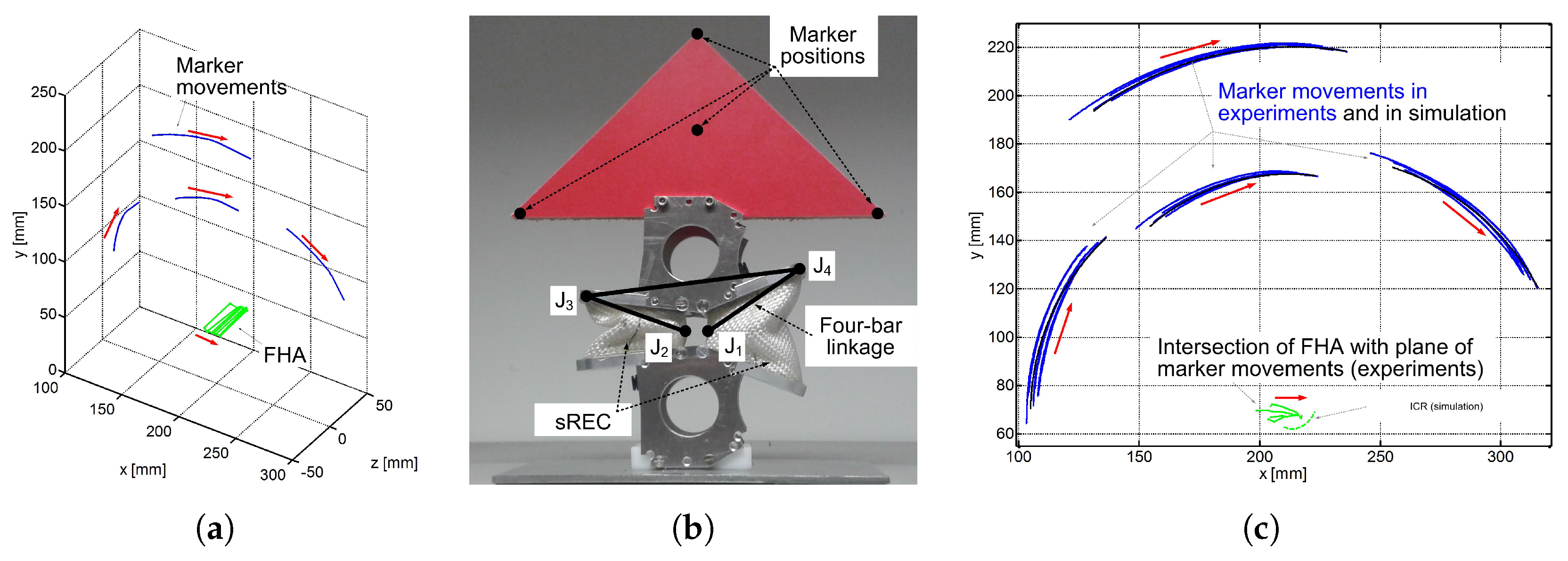
As reference data to verify the kinematic model, the FHA of the sREC-module are analyzed experimentally using a marker based 3D camera system (Vicon Motion Systems Ltd., Oxford, UK) with a maximal resolution of 0.2 mm. Therefore, four retroreflective markers were placed on an extension of the sREC-module to increase the accuracy of the measurement, as can be seen in
Figure 3b. The other part of the module was rigidly attached to a table. The air chambers were inflated to rotate the sREC-module clockwise from left to right and the marker movement was captured by the camera with 50 Hz. Thus, the sREC-module could move freely, with no load applied. All computations were performed using Matlab R2014b (The MathWorks, Natick, MA, USA).
The FHA for a marker movement from an initial orientation to a final orientation is defined by a position vector
s and a directional vector
n. With the four markers at specific time points, the position vector was calculated with the method presented in [
13]. This method uses at least three non-collinear markers
with a position vector
at the initial position and
at the final position respectively. Thus, the marker movement can be described with a rotation matrix
and a translation vector
as follows
To obtain
and
, a quaternion based method, as described in detail by Horn [
14], is used because it seems to be more robust for the presented application. With
, the directional vector
and the rotation angle
was computed, using Matlab built-in functions. The position vector
of the FHA was computed according to Spoor and Veldpaus as follows
With
and
, the FHA is defined in space. To investigate the motion of the sREC-module, the current FHA were computed every 20 data points. As the FHA are of infinite length, the resulting ICR were defined as the distance
d of
j intersection points
Q of the axes with the plane of marker movement. It follows that
where the maximal range of motion for a sREC-module is 36°. The experimental results for one sREC-module as an example are presented in
Figure 3. The determined movement of the markers are shown as solid blue lines and the FHA as solid green lines. The movement direction of markers as well as of FHA is illustrated using red arrows. It can be seen that during rotation, the FHA move about approximately 15 mm in the horizontal direction, with the translation starting at the compressed air chamber. The orientation of the FHA is perpendicular to the plane of marker movement. The development of the kinematic model and a comparison between simulation and experimental results are presented in the next section.
4. Experimental Investigation of Bending Actuator Kinematics
For the next experiment, two sRECBAs are connected in parallel to activate a commercial passive knee brace (SecuTec
® Genu, Bauerfeind AG, Zeulenroda-Triebes, Germany) after removing the internal passive orthesis joints, see
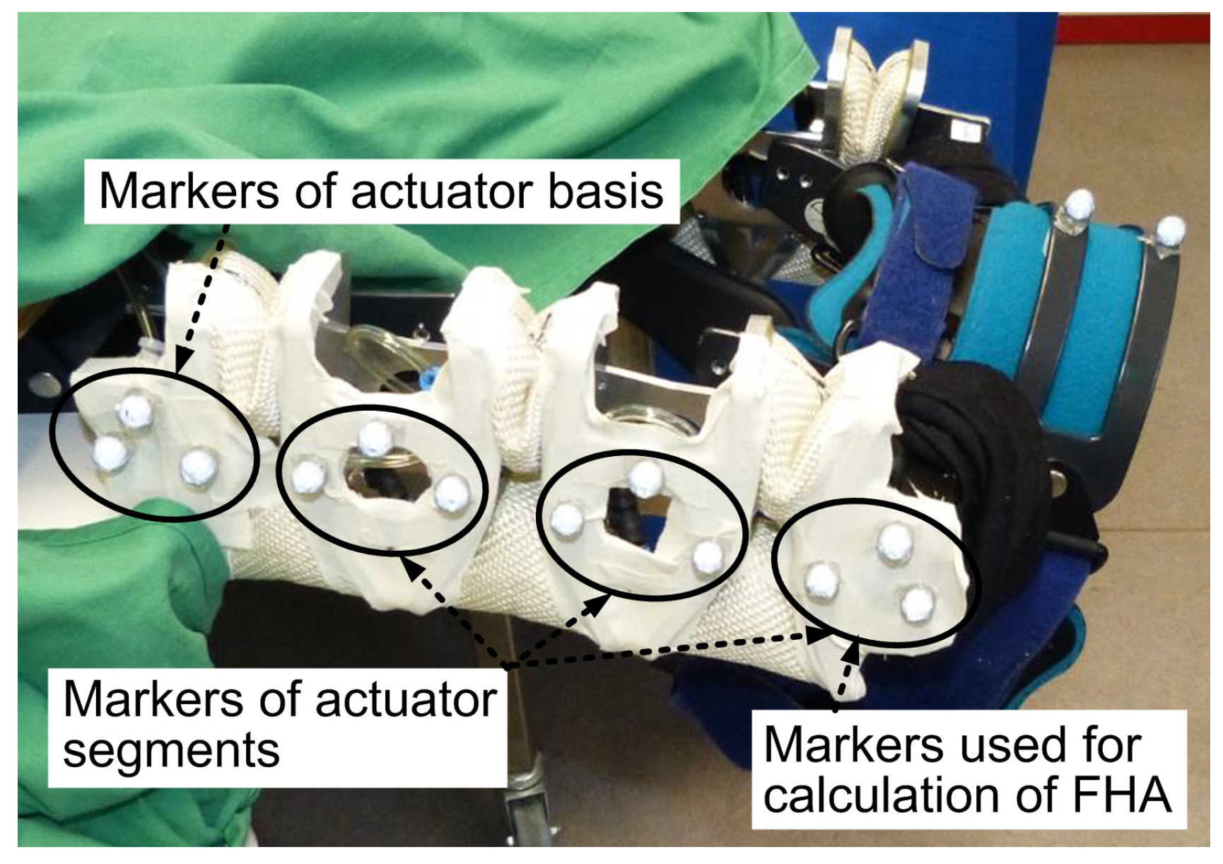
Figure 1b. In this way, a first mock-up of an active knee orthesis is realized as a proof of concept. For basic investigations, the FHA of the knee orthesis are analyzed separately without connecting the device to a human’s extremity. Shown in
Figure 4 is the experimental setup used for experimental investigation of FHA including the activated orthesis based on sRECBA with three markers attached to each sREC-module as well as to the actuator basis, i.e., upper cuff shell (UCS). The markers attached to the lower cuff shell (LCS) are used for calculation of the FHA. The FHA are calculated according to the procedure presented in
Section 3, using the 3D camera system to determine the marker movements.
Three different experiments were performed. During all experiments, the sRECBA is moved from extension to flexion. By moving the sRECBA in specific different ways, the changes of FHA were analyzed with the goal of investigating the reactions on different physical (mechanical) impacts. The sufficient range of changes is a required condition for self-alignment; furthermore, the measured trajectories of the FHA will be used as a sample for comparison with the simulation results (see
Section 5).
In the first experiment, the actuator is not pressurized and only the UCS of orthesis moved manually while the LCS was fixed. During the performed motion, first, the sREC-module connected to the LCS is moved in the whole working range and afterwards the other two actuator sREC-modules are moved together until flexion is completed. The second experiment performed is similar to the first experiment, but in this case, first, the sREC-module connected to the UCS is moved and afterwards the two other sREC-modules are moved together. The different sequence of sREC-modules motion took place because of different external impacts applied to UCS while manual moving. In the third experiment, no external physical (mechanical) impact is provided to the actuator and the sRECBA is pressurized. Therefore, first, the extension actuator chambers are pressurized until extension is reached and afterwards this pressure is reduced until flexion is reached.
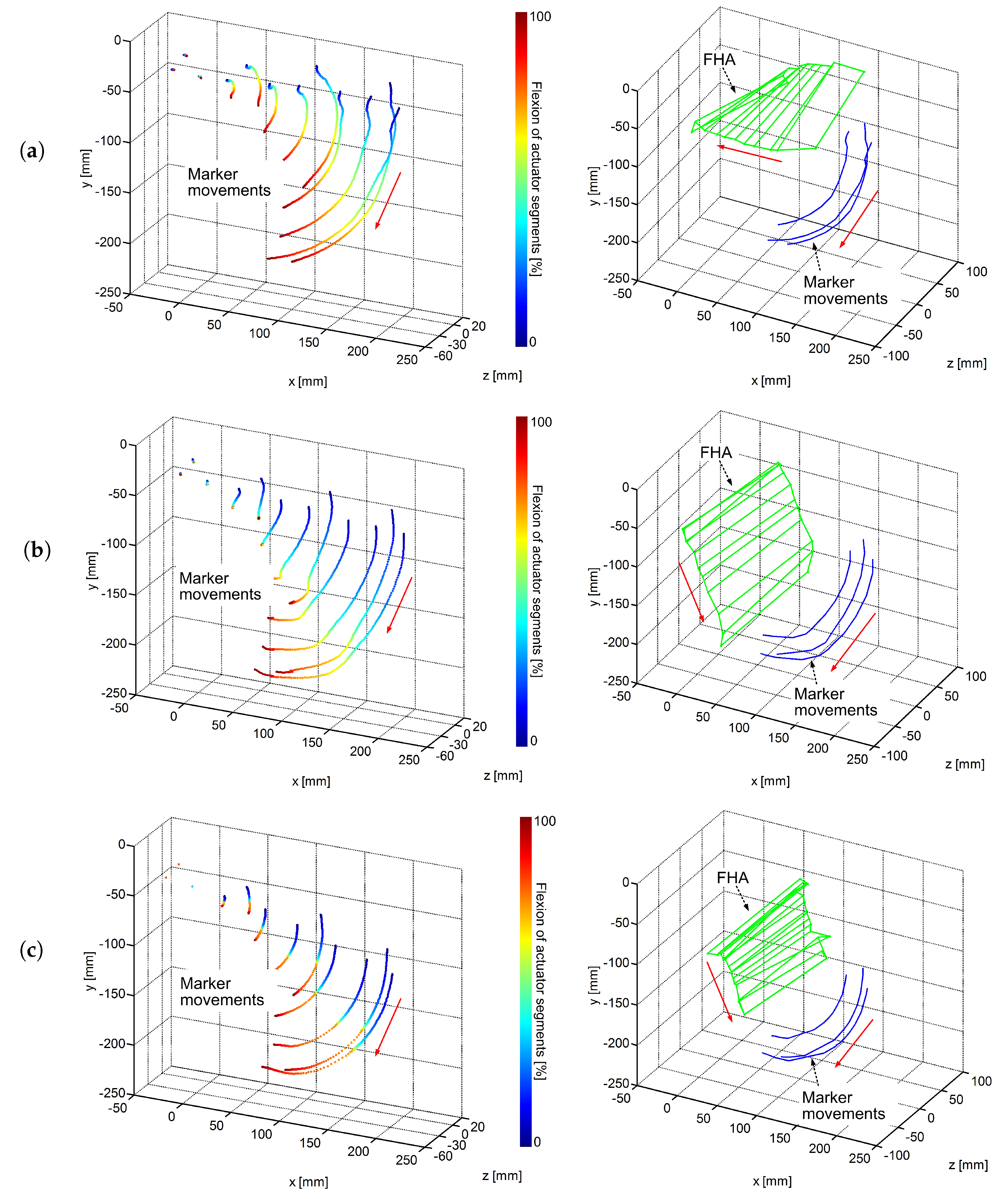
The results of the first experiment are presented in
Figure 5a. The determined marker movements of the actuator sREC-modules and of the actuator basis are shown in
Figure 5a. The colorbar on the right side of the figure shows the percentage flexion of the three single sREC-modules during the performed motion. The direction of the motion is illustration using red arrows. The calculated FHA and the marker movements used for calculation are shown in
Figure 5a. Red arrows are used to illustrate the motion direction of FHA and of markers. The experimental results of the second experiment performed are presented in
Figure 5b. In both cases—compare
Figure 5a with
Figure 5b—the sRECBA is moved manually but in different ways and it can be seen that even if the marker movements of the sREC-modules attached to the LCS part look similar, the sRECBA adapts to the different mechanical impacts that are provided and the FHA change in such a way that the motion of the FHA are in completely different directions with a change in rotation of more than 90°. The difference in the way the actuator sREC-modules move can be seen by comparing
Figure 5a with
Figure 5b. The experimental results of the third experiment performed are shown in
Figure 5c. It can be seen that the motion direction of the FHA is in a similar direction when compared to the results of the second experiment but the overall length of the path of FHA motion is reduced in the case of pressurized actuator chambers.
Based on the results, it can be concluded that the FHA of sRECBA change depending on the applied internal and external impacts, provided by the pressured actuator or human strength. Due to this, it can be assumed that the actuator will be able to provide for implicit self-alignment to the polycentric motion of the human joint axis.
5. Equivalent Kinematic Model of the Bending Actuator and Investigation of Motion in Simulation
After basic experimental kinematic investigations and due to the assumption that each sREC bellow consists of a fixed virtual rotation axis—see
and
in
Figure 3b—it was presumed that the kinematics of the sREC-module can be described in two-dimensional space using a simple four-bar linkage model. To verify this, the intersection of the experimentally determined FHA, see
Section 3, with the plane of marker movements was compared to the ICR calculated using a simulation model based on a four-bar linkage with suitable link lengths. The two additional required rotation axes, see
and
in
Figure 3b, are placed at the end of the upper metal plates of the bellows. According to [
15], the Cartesian coordinates of the ICR
and
can be calculated in the two-dimensional space as follows
where the three constants are defined as
,
as well as
. To determine comparable data, the coordinates of the four required points
and
for
are chosen to be equivalent with the positions of both the outside markers at two points in time used for experimental determination as shown in the previous section, see
Figure 3b. The Matlab toolbox SimMechanics was used for modeling the four-bar linkage.
A comparison of experimental and simulation results is presented in
Figure 3c. The experiment was repeated with four sREC-modules of the same type. The movements of the markers in the experiments are shown as blue lines; the movements of the four points in the simulation are shown as black lines; the intersection of the FHA with the plane of marker movements determined experimentally is shown as solid green lines. The ICR calculated based on the simulation model using the algorithm presented in this section, according to Equation (4), is shown as a dashed green line. The result shows that there is a deviation even in the marker movements of different sREC-modules, which is a result of the non-industrial “handmade” manufacturing process of sRECs. Furthermore, the deviations also depend on the resolution of the camera system. However, it can also be seen that a four-bar linkage model can be used to describe the kinematics of the sREC-module.
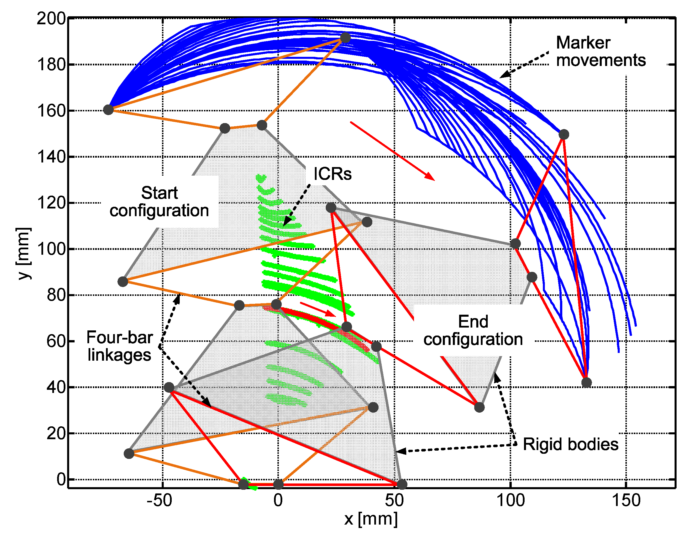
After model verification, a kinematic model of the whole bending joint was implemented as series of three four-bar linkages, as shown in
Figure 6. The actuator model in start and end configuration for the performed motion in the simulation is presented. For the start configuration, the three four-bar-linkages are plotted with orange lines and for end configuration with red lines. The gray areas between the four-bar linkages are connectors (i.e., rigid bodies), representing the metal plates that are used to connect the sREC-modules and to provide for the asymmetric arrangement of the bellows, see
Figure 2. The blue lines represent the movement of the four points that are required to calculate the ICR. The simulation was repeated with different combinations of motion for the three sREC-modules and different velocities. The calculated ICR for the motions performed are plotted in green as well as in red to show exemplarily the ICR for one of the motions. The result shows that the ICR is different for different motions performed and thus the simulation model of the sRECBA possesses the ability to adjust itself to the polycentric movement of the human joint axis in the case of rehabilitation application.
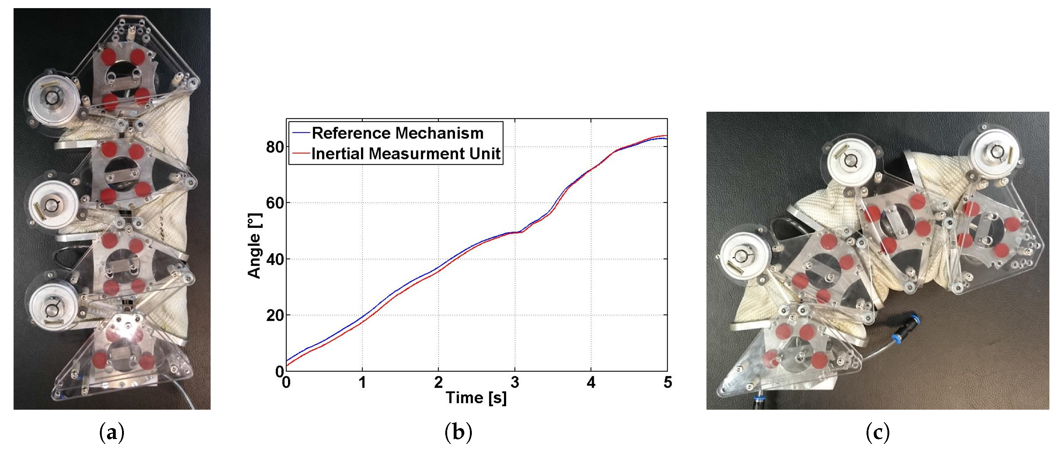
Based on the developed kinematic model, a reference mechanism with a sensor system is realized as shown in
Figure 7. Three high precision incremental encoders (RE
237, Netzer Precision Motion Sensors, Misgav, Israel) are used to measure the angular position of one joint of the three four-bar linkages, respectively. The reference mechanism is mounted on rigid metal plates of the sRECBA with respect to the virtual rotation axis shown in
Figure 7b. The conducted experiments show the sufficient kinematic correspondence between the motions of the sRECBA and the reference mechanism, which move parallel without disturbing one other.
By adding the reference sensor data, the full bending angle of the sRECBA can be calculated.
Figure 3b shows a comparison of the calculated bending angle using the reference sensor system and the angular position of an IMU directly mounted on the sRECBA with bending motion from the stretched to the bent configuration. The sufficient correlation of both graphs indicates the correctness of the developed kinematic model and reference sensor system. The reference sensor system is necessary in order to implement a cost-effective sensor system based on flex sensors, which can be integrated in each sREC and will be used to control the actuator configuration. As mentioned above, to compensate for nonlinearities and the hysteresis effects of flex sensors, an ANN is required; for its training, the reference sensor system will be applied. This topic is, however, beyond the scope of this paper.
Figure 7.
Reference mechanism with a sensor system mounted on the current prototype of the bending actuator (sRECBA) in two different configurations (a,c); Comparison of the measured angle of the reference mechanism with a sensor system and IMU (b).
Figure 7.
Reference mechanism with a sensor system mounted on the current prototype of the bending actuator (sRECBA) in two different configurations (a,c); Comparison of the measured angle of the reference mechanism with a sensor system and IMU (b).
6. Conclusions
This paper presents experimental and simulation-based kinematic investigations of a novel pneumatic bending actuator (sRECBA). This inherent compliant bending actuator is constructed as a series of sREC-modules, utilizing antagonistic arranged patented skewed rotary elastic chambers (sREC) connected with rigid plates. However, without a mechanical rotation axis, the construction allows for sufficient actuator loading and due to its polycentric motion ability it is appropriate for robotic rehabilitation devices with implicit self-alignment to human joint movements.
The concept and the first prototype of the developed bending actuator are presented in
Section 2. For experimental kinematic investigations, the FHA of the basic actuator elements are determined using a 3D camera system, see
Section 3. Afterwards, the FHA of the mock-up of active knee orthesis were determined and analyzed for three different specific motions, see
Section 4. Finally, a simplified 2D kinematic simulation model, as a four-bar linkage, is proposed and its parameters (bar lengths) are determined. The ICR of this model is calculated based on motion simulation and compared to the experimental data. The kinematic model of the sRECBA is developed using a series of three four-bar linkages; the ICR of the bending actuator is analyzed in simulation, and a reference mechanism which corresponds to the motion of the sRECBA was realized, see
Section 5.
The results achieved show that the ICR and the FHA of the sRECBA, respectively, depend on the applied external impacts and changes for different motions performed. Because of this fact, it can be expected that robotic rehabilitation devices using sRECBA will be able to self-adjust to the polycentric movement of the human joint axis.
In the next step, the realized reference sensor system will be used to provide for sufficient reference signals to develop an integrated sensor system based on flex sensors in combination with artificial neural networks to estimate an angular position (configuration) of sRECBA. If the angular position estimation is realized, then the next step is to implement assistive controllers that take into account the patient’s effort, behavior and abilities. Combined with the self-aligning capabilities of sRECBA, it opens the possibility for commercially effective robot-assisted therapy.


 ,
, 