Augmented Reality Guidance with Multimodality Imaging Data and Depth-Perceived Interaction for Robot-Assisted Surgery

1
Singapore Institute of Manufacturing Technology, 138634, Singapore
2
Department of Mechanical Engineering, National University of Singapore, 117575, Singapore
*
Author to whom correspondence should be addressed.
Robotics 2017, 6(2), 13; https://doi.org/10.3390/robotics6020013
Submission received: 30 March 2017
/
Revised: 18 May 2017
/
Accepted: 22 May 2017
/
Published: 24 May 2017
(This article belongs to the Special Issue Robotics and 3D Vision)
Abstract
:Image-guided surgical procedures are challenged by mono image modality, two-dimensional anatomical guidance and non-intuitive human-machine interaction. The introduction of Tablet-based augmented reality (AR) into surgical robots may assist surgeons with overcoming these problems. In this paper, we proposed and developed a robot-assisted surgical system with interactive surgical guidance using tablet-based AR with a Kinect sensor for three-dimensional (3D) localization of patient anatomical structures and intraoperative 3D surgical tool navigation. Depth data acquired from the Kinect sensor was visualized in cone-shaped layers for 3D AR-assisted navigation. Virtual visual cues generated by the tablet were overlaid on the images of the surgical field for spatial reference. We evaluated the proposed system and the experimental results showed that the tablet-based visual guidance system could assist surgeons in locating internal organs, with errors between 1.74 and 2.96 mm. We also demonstrated that the system was able to provide mobile augmented guidance and interaction for surgical tool navigation.
1. Introduction
Motivated by the numerous benefits of minimally invasive surgery (MIS) such as reduction in blood loss, reduction in tissue trauma, and improved recovery times, operation techniques are slowly transitioning from direct open surgery, to indirect, image guided surgery. In traditional open surgery, surgeons identify anatomical structures and perform operations directly. Conversely, in image-guided procedures, surgeons have to mentally establish the spatial relationship between medical image information and the physical surgical site. This additional complexity is mitigated by advances in medical imaging technologies such as computed tomography (CT), magnetic resonance (MRI), and ultrasound (US) imaging, where preoperative and intraoperative medical images are acquired before and during surgery to assist surgeons in planning the surgery and in guiding surgical tool manipulation. Various clinical investigations [1,2,3] have demonstrated that the use of medical image-guidance is able to reduce risk of errors and improve the success rate of operations.
By augmenting the physical surgical field with medical image information and human-computer interaction interfaces, surgeons can incorporate their knowledge with patient-specific conditions to develop optimal surgical plans and subsequently perform the surgery precisely. This was shown by Cura et al. [4], where two-dimensional (2D) medical images (e.g., CT and US) were used in state-of-the-art surgical planning and navigation. Augmented reality (AR), which is visualization technology that overlays computer generated virtual models onto images of the physical world, has recently been explored for surgical guidance. In our previous works, we investigated projection-based visual guidance for percutaneous needle insertion [5,6]. However, as the projections on the patient’s (skin) surface may suffer significant geometric and radiometric distortion, sophisticated algorithms for system calibration were required. Head-mounted displays (HMD) are another heavily studied AR mode for surgical guidance and are generally classified into two main categories—optical see-through and video see-through [7]. Optical see-through HMD applies optical combiners which are partially transmissive and reflective, to combine virtual images with the real world. Video see-through HMD on the other hand, uses a camera mounted on the HMD to captured live feed of the real world and combine virtual images with a scene generator. Although the size of HMDs has reduced over the years, power and data transmission cables still restrict the movement of the surgeon during surgery. In addition, image latency and scene distortion are two significant hurdles limiting the effectiveness of HMDs. Alternatively, AR windows have been explored for surgical guidance. Fichtinger et al. [8] presented a medical image overlay system with a semi-transparent mirror that enabled surgeons to view overlaid 2D CT images that were reflected from a monitor. Mercier-Ganady et al. [9] presented a system for viewing brain activity using augmented reality. Both systems utilize AR windows with little machine-user interaction and mobility, limiting the surgical field visualization to a single fixed position. Rassweiler et al. [10] and Müller et al. [11] both investigated the use of tablet-based AR for visual assistance in percutaneous nephrolithotomy. Both authors applied marker-based tracking and registration for model-patient alignment with limited success—overlaid virtual anatomical models were found to have limited accuracy on the phantom model [10], and the lack of depth perception was identified to be a potential cause of large errors [11].
Existing image-guided systems are limited by the following characteristics: (1) Skilful manipulation of instruments for minimally invasive procedures has a steep learning curve. A large number of practice sessions are often required to narrow the gap between good and poor surgical outcomes; (2) Most systems are narrowly designed for very specific applications with limited input and output options. Surgeons are unable to flexibly reconfigure the system for new minimally invasive procedures; and (3) There is a lack of intraoperative three-dimensional (3D) data support and intuitive human-machine interaction [12].
In this paper, we proposed and developed an interactive medical image-guidance system using tablet-based AR for 3D localization of patient anatomic structures and intraoperative 3D surgical tools navigation. A stereo range sensor (Kinect) was used and its depth data was visualized in a 2D AR display. Virtual visual cues generated by the system were overlaid on the images of patient during surgery. Registration of the virtual visual cues with the physical surgical field was realized by points-model registration algorithm, and a 3D augmented interaction for a mobile tablet AR system was also developed. The structure of this paper is as follows: an overview of the mobile medical AR guidance system is presented in Section 2.1. Section 2.2 describes the patient-model registration, and Section 2.3 describes the AR pose estimation. Section 2.4 describes the use of the touch screen for augmented interaction on a tablet and integration of depth information. The experimental results are reported in Section 3, and discussed in Section 4. Lastly, the conclusion and future work is presented in Section 5.
2. Materials and Methods
2.1. Overview of the AR Surgical Guidance System
The AR surgical guidance system with a robotic surgical system is shown in Figure 1 and Figure 2. The guidance system consists of a tablet computer, a desktop workstation and a Microsoft Kinect v2 sensor. The Kinect sensor provides spatial data acquisition of the surgical field including the outline of the patient’s body, positions of surgical tools and motion of the surgeon’s hands. The Polaris Optical Tracking System [13] could be an alternative for surgical field tracking. The desktop computer, acting as the server in our server-client architecture, is used to accelerate point-cloud data processing. To facilitate the ease of using the tablet computer, a mobile mechanical stand was fabricated with lockable wheels and a gooseneck mount for the surgeon to control and adjust the tablet to the desired position. The mobile mechanical stand allows the gooseneck mount to be positioned securely and to provide additional degrees of freedom (DOF) to the tablet. The gooseneck has a length of 500 mm and holds the tablet rigidly while users are interacting with it. It can be attached to either the surgical bed or the mobile mechanical stand with a c-clamp. The tablet holder can be rotated, providing an additional DOF and allowing for more flexibility. The tablet’s position and pose can be adjusted manually so that the target can be viewed at different viewing angles.
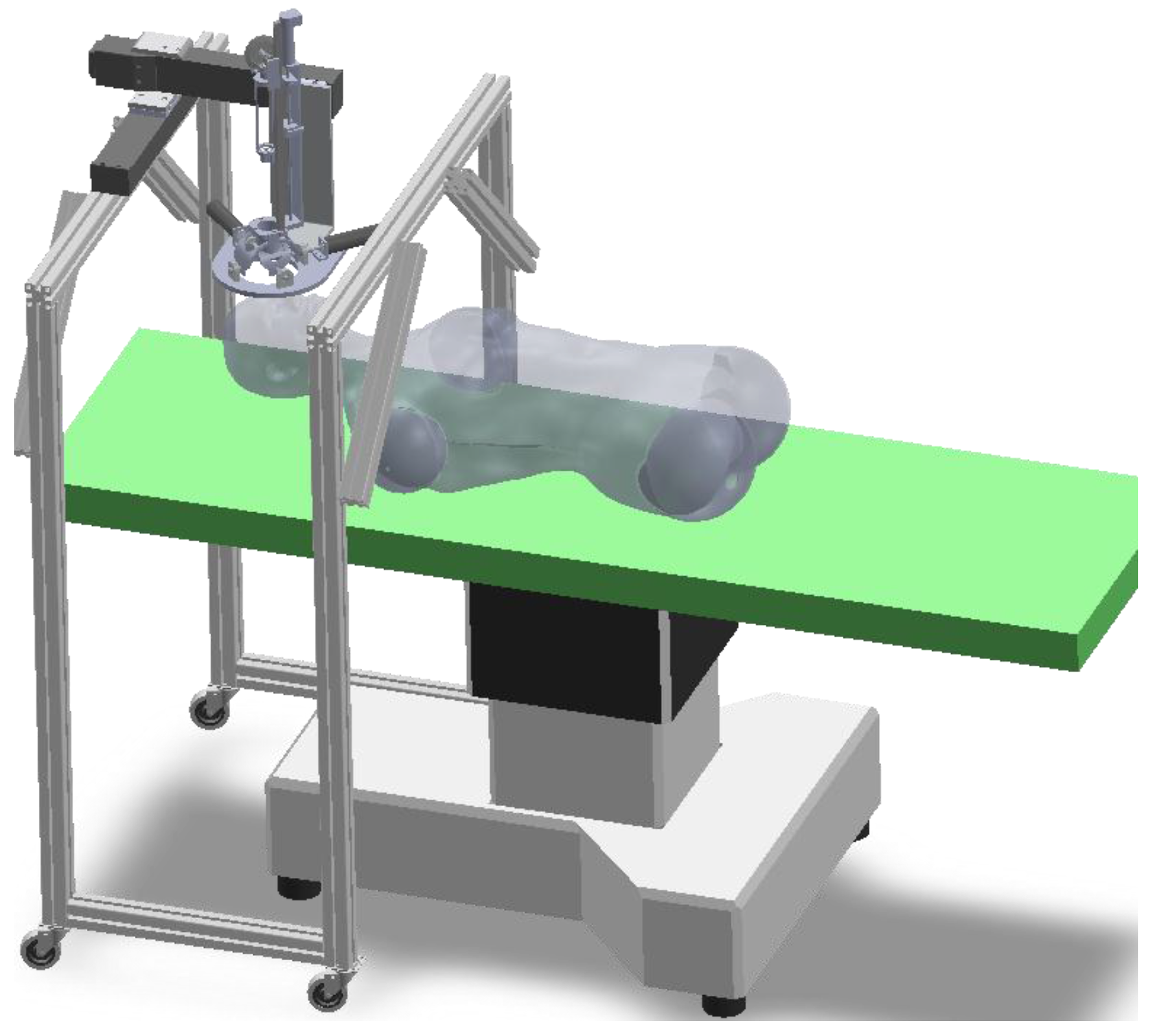
Figure 2 depicts the robotic surgical system utilized in our setup. The system consists of three parts: robot controller, robotic platform and a crossing-arc rotatable mechanism (CARM). The CARM mechanism, comprising of two semi-circular arcs, is used to realize the manipulation of surgical tools within a limited working space. In order to enable the robot to adapt to different procedures, the end effector is designed as a replaceable unit. The movement of the surgical tools (e.g., blunt dissector, heart-shaped forceps) can be discretized into two steps. First, the surgical tool is adjusted to the desired orientation so that it can reach the target point through the access port. Next, the tool is controlled to move along the vector to the target surgical area. The remote center of motion generated by the CARM reduces surgical tool entry time and achieves efficient movement.
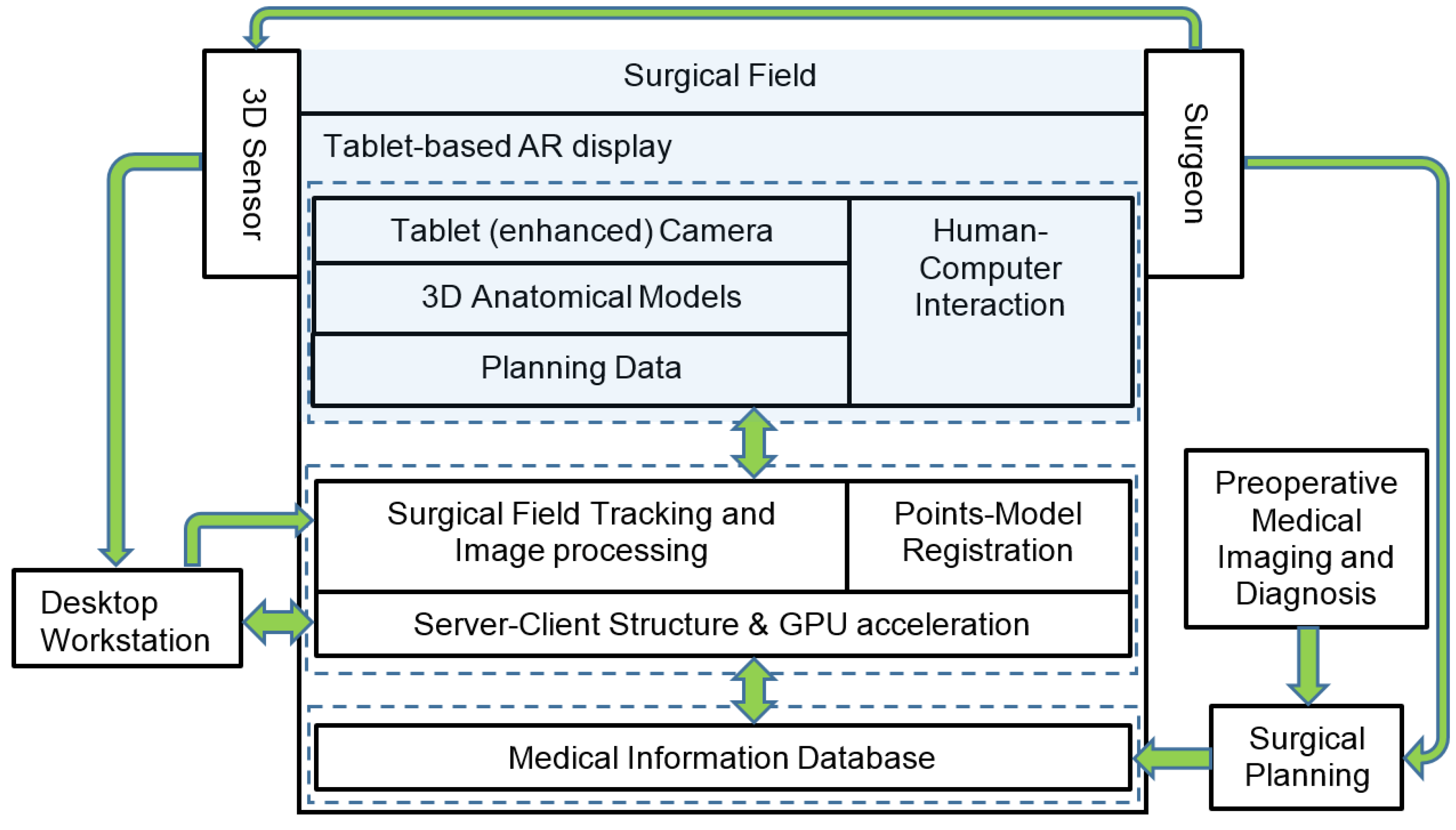
Figure 3 illustrates the general work flow of the mobile AR based surgical guidance. The area highlighted in blue represents the established AR environment on the physical surgical field. The spatial data captured by the Kinect sensor is communicated to the desktop workstation, where higher computational capability with GPU acceleration could be leveraged. Preoperative medical imaging that was obtained before the actual surgery provides surgeons with images of anatomical information for pathological analysis and surgical planning. During surgical planning, surgeons define target operation areas, surgical tools access ports, and trajectories. The structures and organs of high risk are also marked on 2D images and reconstructed 3D models. 3D models of the target anatomic structures and data of the surgical plans are transferred to the tablet via cable or Wi-Fi. In order to register the surgical planning data with the surgical field and patient, the tablet’s built-in camera and the Kinect are used to align the AR model with the patient by vision-based tracking and points-model registration. The depth data that is captured by Kinect is registered in the virtual world’s coordinate system and displayed on the tablet screen. In the guidance procedure, the surgeon is free to decide which type of overlay is to be used for intraoperative surgical guidance, and is able to switch between 2D medical images, 3D models or a hybrid display of both.
2.2. Patient Registration
A challenging problem in AR-based surgical guidance is in the registration of preoperative 3D models with patients intraoperatively. Since the point cloud data captured by the Kinect sensor and the data of medical images are in different imaging modalities, finding data correspondences between the data sets will involve implementation of sophisticated algorithms [5,14] requiring extensive computational resources. While fiducial markers could be used to reduce the complexity of the registration process, marker shift may be unavoidable and could cause significant errors between AR models and the target positions.
In order to achieve efficient registration for surgical guidance, a points-model registration method was developed in our system. This is different from point correspondence approaches [6,15] that use implicit representation of the model set with continuous and smooth distance functions for registration. Without searching for point correspondences between the data sets, the method is independent of point densities, and thus could be more robust to noise and missing data. The registration process is the first step in constructing the surgical AR environment, and subsequently AR pose estimation and updating is used to continuously register the AR position and pose during the surgical guidance process.
2.2.1. Three-dimensional Model Representation
In order to avoid searching for the point correspondences among the large data sets between the patient and his/her reconstructed surface model, 3D models of patient’s outline and anatomic structures are described as implicit polynomials (IP). The virtual 3D models can be registered with the real target object by calculating the spatial transformation to find optimal polynomials to fit the point cloud of the object. The point cloud is captured by Kinect and preprocessed by the desktop workstation. The methods of finding a best IP to fit the 3D model set has been investigated in [16]. A 3D model can be written as an IP of degree d by the equation:
where is the element of the polynomial coefficient for the point clouds . Equation (1) can be rewritten as:
where m is the column vector of monomials and c is the polynomial coefficient vector. To solve the parameters , a three level-sets (3L) algorithm [17] is applied for fitting the implicit polynomial surface to the point cloud due to its computational efficiency. The 3L algorithm is used to generate two level sets, and , from the original data set . With these three data sets, principle components analysis (PCA) [18] is used to generate vectors that are perpendicular to the original data, within a distance of . The polynomial coefficient vector c in Equation (2) can then be computed by:
where
and are matrices of monomials calculated in the original, inner and outer set respectively; are the corresponding expected values in the inner and outer level sets.
2.2.2. Registration between the Point Cloud and the 3D Model
With the IP equation of the 3D model, the registration problem is converted into finding the transformation, including rotation R and translation T, between the point cloud and the model f, which is described by:
is the distance function between the and the model . In order to minimize the distance , estimation of the orthogonal distance [19] is used. This approximation is based on the first order Taylor expansion of the distance function:
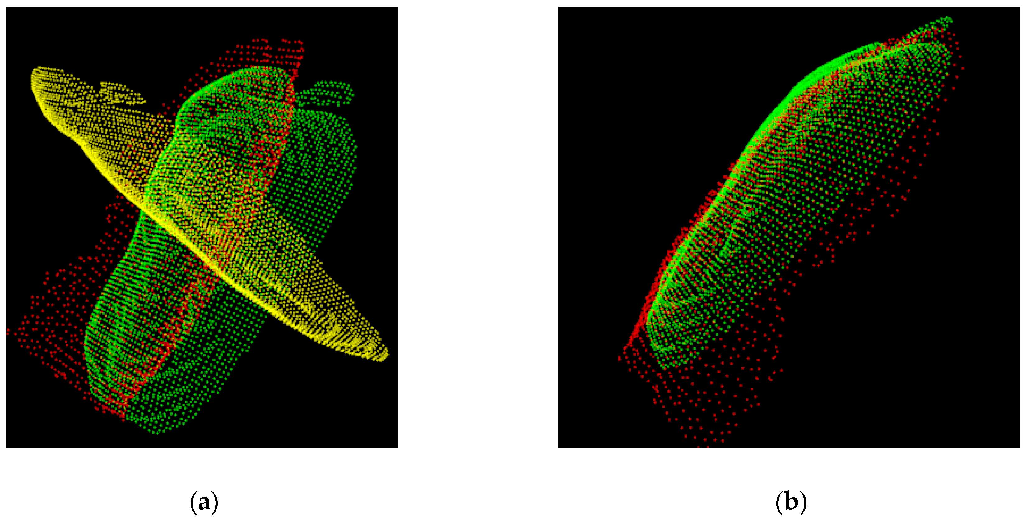
where is the weight to approximate this distance. In this way, the point-to-point correspondence based registration can be performed at a higher level using a curve or surface-to-point cloud based spatial transformation, which is robust to noise (Figure 4).
2.3. Augmented Reality Pose Estimation
With the initial registration between the virtual models and patient, the intraoperative AR guidance procedure requires computation of the continuous spatial relationship between the virtual visual assistance information, physical surgical field, and patient and target anatomical structures. This section describes the construction of the mobile surgical AR environment in continuous frames, including markerless feature tracking and AR pose estimation. While marker-based AR construction, such as Quick Response (QR) code and black-white image based patterns are often used, such methodologies may not be suitable for surgical applications, due to marker shift errors and the possibility of operational obstruction. In addition, it may be unfeasible to attach markers on patients or within the surgical area in some situations. Hence in this study, we developed a markerless and natural feature-based method that uses skin and tissue textures for intraoperative AR pose estimation.
2.3.1. Feature Detection and Tracking
In order to reduce the computation intensity of object tracking on the tablet computer, sparse sampling for feature extraction and Center Surrounded Extremas (CenSurE) [20] can be used for real-time feature detection. The sparse samples are acquired by computing bi-level Laplacian of Gaussian and filtering weak responses. By applying the Harris measure,
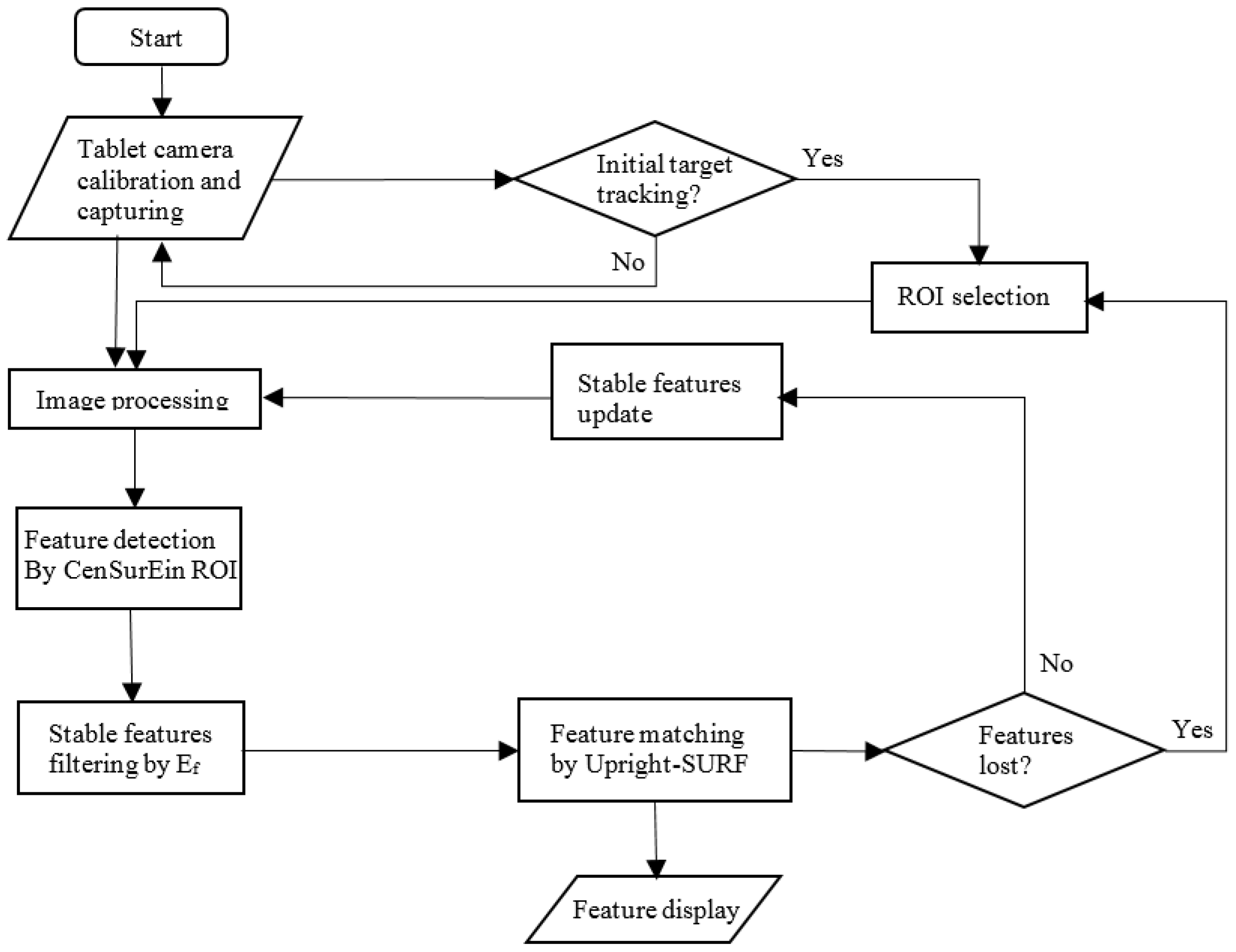
where is the response function, and and are its derivatives along x and y respectively. The local extrema with strong corner response can be detected. The summations in Equation (7) are over a window with a length proportional to the scale of the feature. The length of the window is the length of the outer box at the scale of the feature. Before the tracking begins, surgeons are required to select the region of interest (ROI) in the surgical field on the tablet screen. Figure 5 illustrates the workflow of the feature detection and matching process.
In the frames captured by the tablet camera (Figure 5), a Gaussian smoothing kernel with a 4 × 4 window is applied to filter noisy data. In order to enlarge the field of view of the ROI without reducing the image quality, a tablet camera attachment can be used. Features are then extracted from the area that was selected by surgeons and are initialized as landmarks for subsequent frame tracking. By comparing the modified descriptor Upright Speeded-up robust features (SURF) [21] between the preceding and current frames, features with similar characteristic scales and similar characteristic orientations are considered as pairs of correspondence. Since neighboring features are expected to move in a similar direction and distance because of the nature of tissue deformation, false positive matches of temporal feature matches can also be filtered by examining the movement of neighborhood features. In order to efficiently track stable key features, scale-space extrema , can be used to narrow down the number of possible matches, reducing unnecessary descriptor comparisons and improving performance, as well as the reducing the possibility of incorrect matches:
where G is convolution of a variable-scale Gaussian, is an input frame, and S is a scale space of an image produced by:
In the continuous frame tracking process, features are independently tracked by maintaining a list of features that have been previously found. All features that were matched previously are updated with new locations and descriptors. The remaining new unmatched features are appended to the list.
In the feature tracking process, a threshold k is defined by:
to evaluate if the features are consistently detected, where is number of times that feature has been found. represents average number of tracking frames. If k < d, the feature Ki is deleted, otherwise it will be retained on the tracking list. In order to avoid missing new features due to noisy points, 15 frames after the initial detection are chosen as samples for evaluation of k. In this way, a reference frame of feature points is continuously constructed and updated during the AR tracking process.
2.3.2. AR Pose Estimation and Update
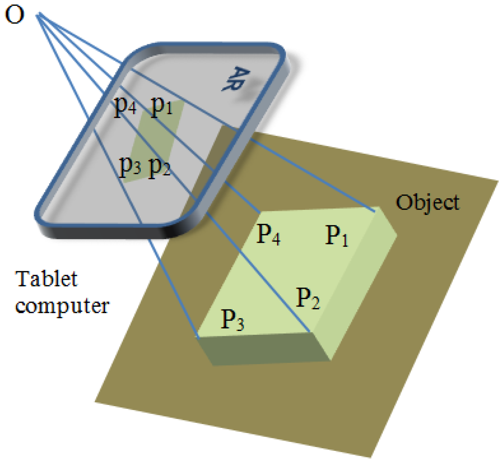
AR pose estimation aims to spatially ensure that the overlay of virtual models is consistent with the surrounding real environment. It determines how the virtual object is displayed, based on the user’s view perspective (tablet screen) in the real world. The AR pose is described by its spatial position coordinates and orientations, which consists of rotation angles around the three coordinate axes , respectively. Figure 6 illustrates the geometry of the AR pose estimation in a tablet window. The points P1 to P4 are 3D points in the real world coordinate system, and the p1 to p4 points are their corresponding projections on the camera’s image plane. The spatial transformation from the known object Pw to the virtual object pw in the tablet’s window can be described by the camera’s intrinsic matrix and extrinsic matrix between and . We assume that the point O is the user’s eye position.
Using standard camera calibration methods, camera intrinsic parameters including focal length f, and principle point Ox, Oy can be determined. The corresponding points (Pi, pi) can then be expressed by homography H in the equation p = HP:
The homography H can be rewritten with a camera intrinsic and spatial transformation matrix as:
where ri and ti are the elements of the rotation and translation matrix between Pi and pi respectively. With the estimated homography H, the 3D models (anatomic structures and planning data) are transformed from the world coordinate system to the virtual camera’s coordinate system. The view matrix derived from the matrix H defines the position of the camera in the OpenGL ES 3D virtual environment. By going through the rendering pipeline of OpenGL ES with the projection matrix and the view port transformation in each frame, the virtual object can be effectively rendered in the scene of the physical world.
With the tracked features in Section 2.3.1, random sample consensus (RANSAC) can be used to calculate the optimal homography matrix between the given feature correspondence and in the preceding and current frames. Object pose in the preceding frame is used as the initial pose of the current frame. The estimated homography for pose update can be computed by . In this way, a 3D virtual object with a specific pose seen in the physical world can be continuously rendered on the tablet screen.
2.4. Interactive Surgical Guidance
Besides the built-in camera that can be considered as the main sensor of a tablet computer, other sensors such as the tablet’s touch screen, orientation sensor and accelerometers may provide integrated guidance information during surgery. With these built in sensors, tablet computers may assist surgeons in achieving smart surgical guidance in the following aspects: (1) Surgeons can stabilize the view of the risky areas by using information from accelerometers for compensation. This will be particularly useful for stable surgical tool manipulation; (2) Orientation sensors can aid in the viewing of 3D anatomical models with the mobile tablet; (3) Surgeons can make intraoperative planning, such as selecting insertion ports and marking specific operation zones through the touch screen; (4) Surgeons are able to toggle the AR display between 2D medical images (e.g., preoperative CT and MRI image sequences) and 3D models, through the controls on the touch screen.
This section describes the use of the touch screen for augmented manipulation on the tablet. The built-in forward camera of the tablet can also provide an alternative for touchless gesture recognition as in [22] for AR operation if sterility is strictly required.
2.4.1. Touch Control for 3D AR Object Manipulation
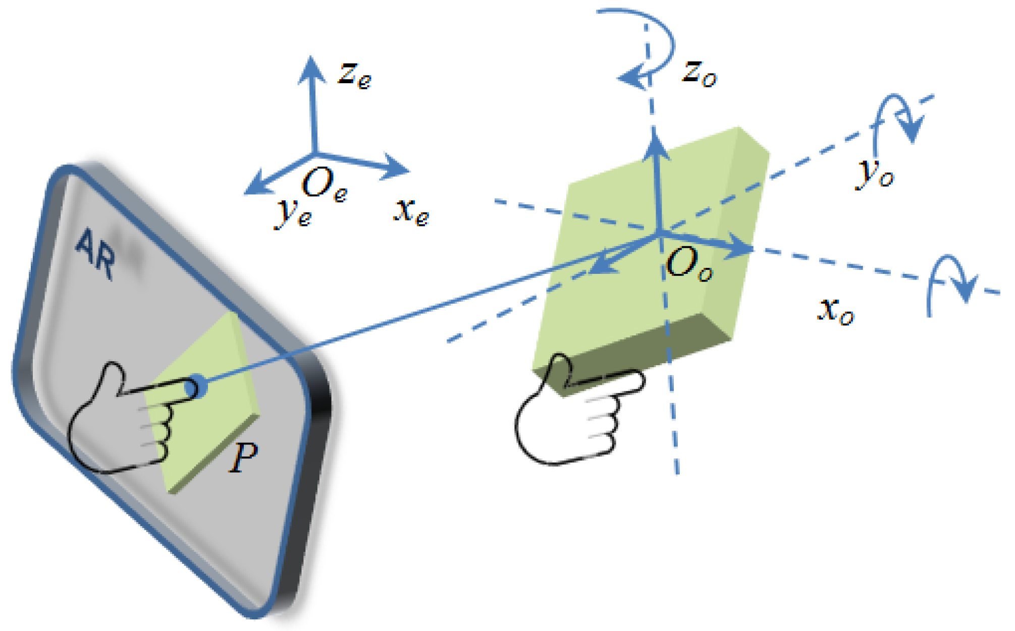
Virtual arm-extension and ray-casting are two main techniques for grabbing and manipulating virtual objects in a virtual environment. In order to realize interactions with 3D AR objects, a hand-centric object manipulation with extended ray casting is developed. Ray-casting is used to select an object in the AR environment. A mobile ray-casting can be constructed by backprojecting the finger-tip touch point Tp = (x; y) on the tablet screen into a 3D AR environment. The direction of the virtual ray, casted from the current virtual camera position, can be estimated by the current tablet camera pose. The first virtual object that the ray intersects is the object selected by the user. With the OpenGL ES pipeline, ray-casting and virtual object selecting can be realized by transforming the touch point P into a 3D norLimalized device coordinate system, and then establishing a 4D homogeneous clip space or intersection computing between the casting ray and the objects. Translation and rotation of a virtual object in the AR space are realized by mapping the current virtual camera’s pose to the target object Oo, as shown in Figure 7.
When a user picks an AR object at point P on tablet screen, the virtual object Oo is selected by ray-casting. Current hand manipulating position He can be mapped to the virtual hand position Hv, from the Oe to the Oo coordinate system. In each frame of the AR scene, object Oo’ translation is calculated by:
where . Rotation of the object can be performed by setting hand manipulation position P to the center of the object Oo. To change the size of the virtual object, the current center position of the object is reused, and the displacement of the virtual hand determines the size of the object.
2.4.2. Motion Tracking and Depth Integration
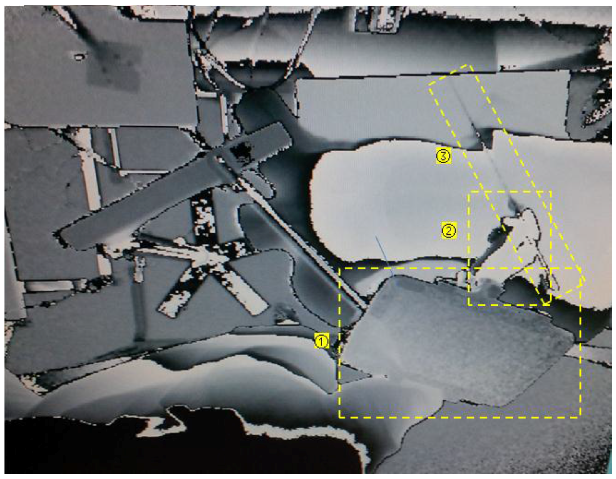
For human-machine interaction in surgical guidance, the tablet camera captures images of the ROI in the physical world, while the Kinect retrieves the depth information of the patient and surgeon position, hand motion, and surgical tool manipulation (Figure 8). The surgical tools’ positions are registered with the target organ model Vo in the virtual world coordinate system by the equation:
where is the spatial transformation between the real surgical tools and the real target organs in the Kinect-based world coordinate system. The position of the real target organ Vr is identified by the surgeon and calculated from the imaging parameters of the medical image data set. With Equation (14), the virtual needle position in the AR surgical field can be computed with respect to the virtual organ Vo. The surgeon’s hand motion can be used to provide robust needle pose estimation (Figure 8). The server-client architecture with GPU acceleration support is used to calculate the real-time augmented interaction between the actual needle and the virtual organs, and the calculated interaction results, including virtual needle position and guidance information can be transferred to the tablet wirelessly.
During the augmented interaction process, the 3D surface data of the surgical field (patient) is compared with the 3D model reconstructed from preoperative medical images, to monitor patient position variations. Three-dimensional data preprocessing techniques, such as sampling, smoothing, and segmentation, are used within the ROI to reduce computational intensity. The depth images provide actual spatial information for the tablet 2D AR environment, and together with the visualized 3D models, providing interactive depth perception in the 2D display. Cone-shaped layers are constructed in this study to represent the available workspace at different depth scales. As the objects displayed in the tablet-based AR environment have 3D coordinates that are registered with the patient body, surgeons are able to define or mark target locations and areas in the physical world through the touchscreen controls on the tablet. Intraoperative planning can thus be achieved through the tablet’s screen.
3. Results
Tablet-based AR surgical guidance was evaluated on two experimental setups: (1) An AR environment for vocal fold microsurgery. (2) An AR environment for percutaneous liver ablation. Both setups utilized mannequins with a tablet and a Kinect position setup similar to that shown in Figure 2. A mechanical stand with an attached flexible goose-neck mount was used to support tablet placement so that the tablet could be moved to an arbitrary position for AR construction. The accelerometer sensor of the tablet was used to detect and compensate for unexpected tablet shift after it was deployed during the procedure. The Kinect v.2 sensor was positioned over the surgical field encompassing the patient (mannequin) and the surgeons’ working space. The desktop workstation which received 3D data from the Kinect sensor was connected to the tablet wirelessly. The system was executed on a Google Nexus 10 (Samsung Electronics), with an Android operating system, dual-core of 1.7 GHz Cortex-A15 processor and 2 GB memory. The desktop workstation with MS Windows 7 had an Intel Xeon processor with 2.53 GHz, 12 GB memory and an NVIDIA Tesla GPU.
3.1. System Calibration
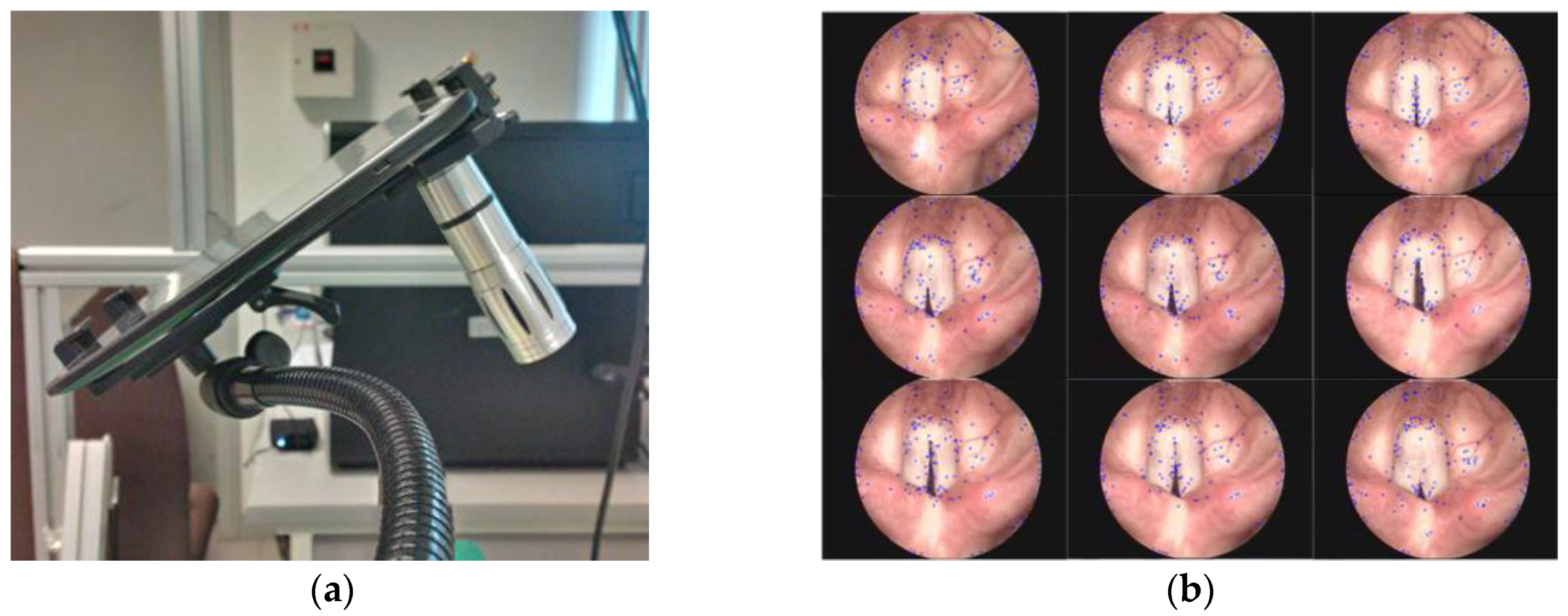
Camera calibration is a necessary step to acquire camera intrinsic parameters and estimate tablet pose in the physical world. By using the feature detection and matching algorithm described in Section 2.3.1, transformation between feature correspondences were calculated, and the intrinsic parameters and homography were obtained. The results were used on a setup for vocal fold microsurgery as depicted in Figure 9.
In order to test features detection and tracking on a non-rigid body, video clips of human vocal fold motion was used. As shown in Figure 10, the feature point cloud could be detected and tracked on the non-rigid body in continuous frames. The stable feature list was updated by scale-space extrema described in Section 2.3.1. With the feature points tracking, the AR pose could be estimated.
For the second experimental setup for liver ablation, Figure 11 shows the registration of the 3D plasticine models reconstructed from CT images, with their corresponding physical models in the mannequin. The registration results found that the 3D models were overlaid on the corresponding physical mannequin with errors between 0.53 mm to 3.62 mm.
3.2. AR Display for Interactive Visual Guidance
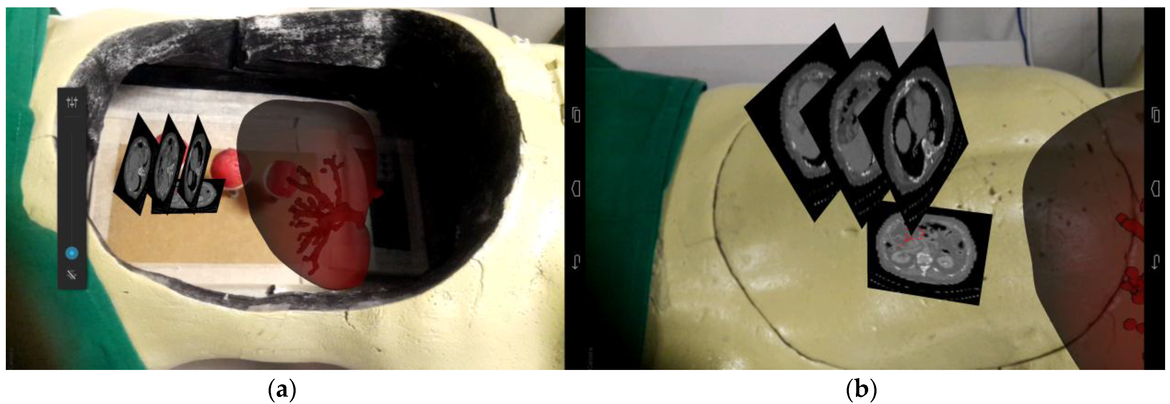
Figure 12 shows a hybrid AR display that consists of 2D CT image slices and 3D liver models. By using one of the plasticine models as a selection point, we were able to register and display the organ model in the mannequin body. Similarly, additional information such as CT images obtained preoperatively could be selected and displayed near the target surgical area. Specific anatomical structures or areas (Figure 12b) could be marked on the CT images for intraoperative guidance reference.
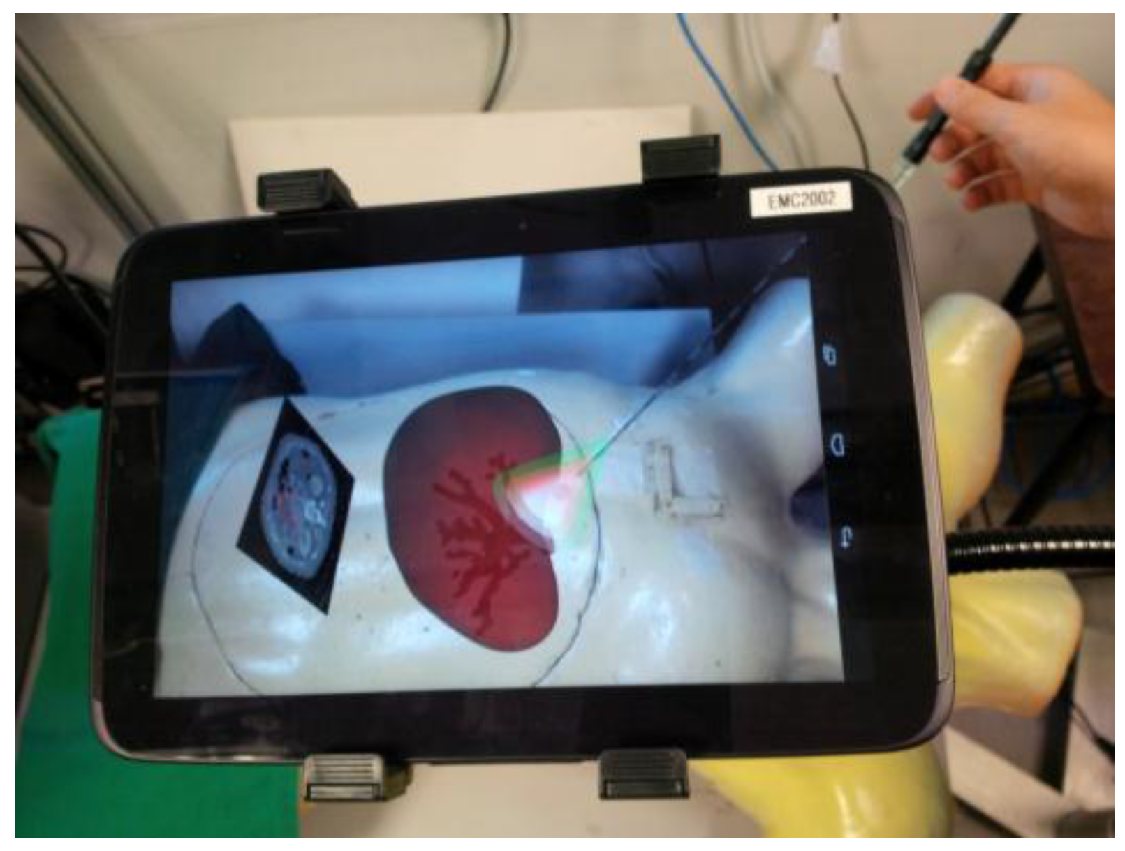
Figure 13 shows the tablet AR surgical guidance for minimally invasive RF needle insertion on the mannequin. The anatomic models were loaded from a tablet computer and registered at a preplanned position. The transparency of the organ (liver) model was set to 50% to display the internal blood vessels at high risk. The cone volumes, with different colors (green, red, and pink) covering the target area, represented the safe working spaces and depth differences for needle insertion guidance. With the CT image and 3D anatomical models’ guidance, users were able to locate the target area and critical vessels. Percutaneous RF needle insertion could be achieved by multimodality image guidance.
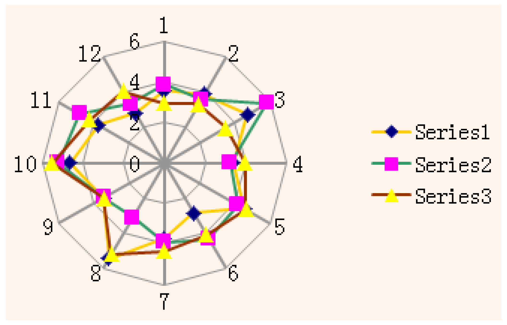
Figure 14 shows the RF needle errors that were produced by tablet AR guidance on a static mannequin where three plasticine models were made to mimic the tumors. Three groups of tests were conducted on the plasticine models. The plasticine models were able to clearly retain the insertion marks, including the insertion points and trajectories. The results indicated that the AR visual guidance enabled users to manipulate the RF needle to reach specified points from different directions, confirming the feasibility of the visual perspective-based AR guidance. All tumor data (plasticine models) were collected from CT scans post-insertion. The Figure 14 shows three groups of insertion tests and the distribution of AR guided insertion points, with the errors produced by the AR guidance falling within a range of between 1.74 mm to 2.96 mm.
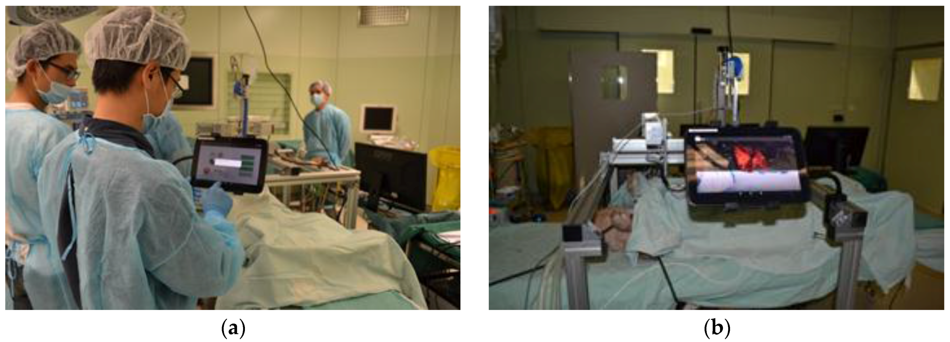
A preliminary system test in a real surgical environment for the robotic platform and parts of the tablet human machine interface (HMI) functions was carried out (Figure 15). In order to efficiently acquire the medical data after CT scanning, a 3D level set method was applied for the segmentation of target organs. Parameters of the level set model were automatically computed, based on the homogeneous region specified by the user. A cuboid that contained the whole target object was also generated, according to the specified rectangle, so as to remove irrelevant parts of the volume. After that, an anisotropic diffusion filter was applied to the images, in order to reduce noise while preserving salient features. Finally, level set segmentation was performed on the filtered data to produce the surface of the target. In addition, morphological operations were also performed to refine the segmentation result.
For surgical path planning on the tablet computer, the user was tasked to specify the insertion and target points from which the surgical path could be generated automatically. A spherical model was generated to represent the target region where the user could move the spherical model to the target, via planning tools provided by the tablet computer. After the target region was located, the intermediate section of the sphere was selected as the target plane, and the target points were distributed on this plane. After the surgical path and reconstructed models were ready, the data was then transformed into the marker coordinate system in which an AR registration could be implemented to align the data with the physical coordinate system.
4. Discussion
Evaluation of the medical image guidance using a tablet computer and Kinect device for intuitive surgical guidance was conducted in the experiments. The system was found to be capable of assisting surgeons in visually detecting the hidden organ models and guiding needle insertion to the target tumor(s). The guidance accuracy was dependent on AR registration between the reconstructed mannequin model and its corresponding physical features, and Kinect-based tracking accuracy and stability. Augmented interaction with a touch screen enabled the intraoperative surgical navigation to be direct, intuitive and simple.
In the experiment, the overall system setup time took around 18 min. It included the following steps: (1) Segmentation of organ models in the CT image volume; (2) Hardware setup including a mechanical stand, tablet, Kinect and desktop workstation; (3) AR registration of the target organ model and needle; and (4) Identification of the 3D position of target organ and critical vessels on the tablet screen. The mobility of the guidance system enabled it to be flexibly deployed around the patient (mannequin), depending on the surgeon’s preference, easing positioning with peripheral equipment and devices. While in typical clinical applications [23,24], this may contradict the principles of stationary navigation, the mobility of the system facilitates the observation of AR objects from different view perspectives. In this study, we developed a prototype of the medical AR system. The gooseneck mount was a temporary choice to mimic a flexible robotic arm. In the future work, a robotic arm will be specifically designed and developed. This robot arm could provide robust and automated motion to support the tablet. The tablet pose and location could also be easily recorded. In addition, it would be easier for a robot arm to conform to aseptic standards.
Software modules on the tablet computer offered functions of (1) Semi-automatic segmentation; (2) 3D organ model overview and selection; (3) Model-patient registration; (4) A close-up view of surgical field; and (5) Interactive needle guidance. The software development consists of three parts: an android-based module solely for user interface and system management, a hybrid-code module for open source software de-velopment kit (SDK) integration including OpenCV, Point-cloud library (PCL), Vuforia [25] and jPCT-AE [26], and a Windows-based module for Kinect data acquisition and processing [27]. With the rapid development of tablet hardware, mobile AR guidance in clinical applications is becoming increasingly achievable, especially with significantly improved CPU power, memory, high-definition display and multiple built-in sensors. Dual-core processors have been widely used in tablet computers with 2.3 GHz and 2 GB RAM, and the storage of tablets has reached 64 GB. NVIDIA has also developed GPUs (Tegra series) for mobile devices for sophisticated graphical rendering and parallel computation. Additionally, the network accessibility of tablets enables surgeons to acquire more reference information from external sources like the local network or the Internet. Tablet computers thus provide an alternative way to display medical image information and construct an augmented surgical field or system of surgical visual guidance.
Compared to other works on tablet computer-based AR systems for image-guided surgery, our system has successfully incorporated multimodality medical imaging data and depth information acquired using the Kinect sensors. A main drawback during the needle insertion guidance was the lack of GPU acceleration support for the Android system. While the system could function smoothly for a simple position evaluation of an inserted needle, utilizing more complex organs and vessels would result in a slowdown in computation speed. Nevertheless, with the rapid improvements in tablet technology, we expect this issue to be mitigated in the future.
5. Conclusions and Future Work
We have proposed, designed and developed a tablet-based surgical guidance system that is able to provide surgeons an intuitive visual assistance and augmented interaction with a Kinect sensor. Computer graphical models are overlaid on a surgical field to reveal the hidden anatomic structure and provide necessary virtual guidance information, together with a variable view perspective. Registration of the 3D anatomical models with the patient is carried out by a points-model registration algorithm that reduces the heavy computational load on the tablet computer. Natural feature detection and tracking algorithms are developed for real-time estimation of the AR pose, which enables the tablet to render the models without repetitive registration. With the inclusion of the Kinect sensor, 2D AR guidance on the tablet can be extended to a 3D AR space. Surgeons are able to manipulate surgical tools in a 3D augmented surgical field via the tablet computer.
We are aiming to incorporate a commercially available open-sourced structure sensor into the system to directly provide color depth images. The structure sensor is to be embedded on the tablet and will replace the Kinect sensor. GPU-specific computational algorithms could be developed for intraoperative augmented interaction between the surgical tools and tissue deformation. Our system can also be extended to include the control and manipulation of a robot for RF needle insertion. In [22], we described a natural gestures control method for robust interaction with the AR and the surgical robot system. The front camera of the table computer can be used for recognition of hand gestures of surgeons so that strictly sterile interaction can be realized.
To realize medical AR guidance in a real surgical environment, non-rigid registration and soft tissue deformation-based simulations are critical issues. In future works, non-rigid object registration methods will be developed to incorporate tablet-based rigid object registration for medical AR construction. An offline soft tissue deformation-based simulation could be an effective supplementary to the non-rigid registration. Ex vivo and in vivo experiments will then be carried to test the improved medical AR system.
Acknowledgments
This work is supported in part by National University of Singapore FRC Tier 1 Grant (WBS: R265-000-446-112) and Agency of Science and Technology of Singapore (A*Star) BEP2013 POC Grant (WBS: R-265-000-522-305).
Author Contributions
Rong Wen and Chee-Kong Chui conceived and designed the experiments; Rong Wen and Chin-Boon Chng performed the experiments; Rong Wen and Chin-Boon Chng analyzed the data; Rong Wen, Chin-Boon Chng and Chee-Kong Chui wrote the paper.
Conflicts of Interest
The authors declare no conflict of interest.
References
- Perrin, D.P.; Vasilyev, N.V.; Novotny, P.; Stoll, J.; Howe, R.D.; Dupont, P.E.; Salgo, I.S.; Nido, P.J. Image guided surgical interventions. Curr. Probl Surg. 2009, 46, 730–766. [Google Scholar] [CrossRef] [PubMed]
- Thomas, G.W.; Johns, B.D.; Kho, J.Y.; Anderson, D.D. The Validity and Reliability of a Hybrid Reality Simulator for Wire Navigation in Orthopedic Surgery. IEEE Trans. Hum. Mach. Syst. 2015, 45, 119–125. [Google Scholar] [CrossRef]
- Yang, C.; Chen, Y.; Tseng, C.; Ho, H.; Wu, C.; Wang, K. Non-invasive, fluoroscopy-based, image-guided surgery reduces radiation exposure for vertebral compression fractures: A preliminary survey. Formos. J. Surg. 2012, 45, 12–19. [Google Scholar] [CrossRef]
- Cura, J.L.; Zabala, R.; Iriarte, J.I.; Unda, M. Treatment of Renal Tumors by Percutaneous Ultrasound-Guided Radiofrequency Ablation Using a Multitined Electrode: Effectiveness and Complications. Eur. Urol. 2010, 57, 459–465. [Google Scholar] [CrossRef]
- Wen, R.; Chui, C.; Ong, S.; Lim, K.; Chang, S.K. Projection-based visual guidance for robot-aided RF needle insertion. Int. J. Comput. Assist. Radiol. Surg. 2013, 8, 1015–1025. [Google Scholar] [CrossRef] [PubMed]
- Wen, R.; Yang, L.; Chui, C.; Lim, K.; Chang, S. Intraoperative visual guidance and control interface for augmented reality robotic surgery. In Proceedings of the 8th IEEE International Conference on Control and Automation 2010, Xiamen, China, 9–11 June 2010. [Google Scholar]
- Birkfellner, W.; Huber, K.; Watzinger, F.; Figl, M.; Wanschitz, F.; Hanel, R.; Rafolt, D.; Ewers, R.; Bergmann, H. Development of the Varioscope AR. A see-through HMD for computer-aided surgery. In Proceedings of the IEEE and ACM International Symposium on Augmented Reality, Munich, Germany, 6 October 2000. [Google Scholar]
- Fichtinger, G.; Deguet, A.; Masamune, K.; Balogh, E.; Fischer, G.S.; Mathieu, H.; Taylor, R.H.; Zinreich, S.J.; Fayad, L.M. Image overlay guidance for needle insertion in CT scanner. IEEE Trans. Biomed. Eng. 2005, 52, 1415–1424. [Google Scholar] [CrossRef] [PubMed]
- Mercier-Ganady, J.; Lotte, F.; Loup-Escande, E.; Marchal, M.; Lecuyer, A. The Mind-Mirror: See your brain in action in your head using EEG and augmented reality. In Proceedings of the IEEE Virtual Reality Conference, Minneapolis, MN, USA, 29 March–2 April 2014. [Google Scholar]
- Rassweiler, J.J.; Müller, M.; Fangerau, M.; Klein, J.; Goezen, A.S.; Pereira, P.; Meinzer, H.P.; Teber, D. iPad-assisted percutaneous access to the kidney using marker-based navigation: Initial clinical experience. Eur. Urol. 2012, 61, 628–631. [Google Scholar] [CrossRef] [PubMed]
- Müller, M.; Rassweiler, M.; Klein, J.; Seitel, A.; Gondan, M.; Baumhauer, M.; Teber, D.; Rassweiler, J.J.; Meinzer, H.; Maier-Hein, L. Mobile augmented reality for computer-assisted percutaneous nephrolithotomy. Int. J. Comput. Assist. Radiol. Surg. 2013, 8, 663–675. [Google Scholar] [CrossRef] [PubMed]
- Yaniv, Z.; Cleary, K. Image-guided procedures: A review. Comput. Aided Interv. Med. Robot. 2006, 3, 1–63. [Google Scholar]
- Inoue, D.; Cho, B.; Mori, M.; Kikkawa, Y.; Amano, T.; Nakamizo, A.; Hashizume, M. Preliminary study on the clinical application of augmented reality neuronavigation. J. Neurol. Surg. Part A Cent. Eur. Neurosurg. 2013, 74, 071–076. [Google Scholar] [CrossRef] [PubMed]
- Figl, M.; Rueckert, D.; Edwards, P. Registration of a Cardiac Motion Model to Video for Augmented Reality Image Guidance of Coronary Artery Bypass. In Proceedings of the World Congress on Medical Physics and Biomedical Engineering, Munich, Germany, 7–12 September 2009. [Google Scholar]
- Fornaro, J.; Keel, M.; Harders, M.; Marincek, B.; Székely, G.; Frauenfelder, T. An interactive surgical planning tool for acetabular fractures: Initial results. J. Orthop. Surg. Res. 2010, 5, 50. [Google Scholar] [CrossRef] [PubMed]
- Zheng, B.; Takamatsu, J.; Ikeuchi, V. An adaptive and stable method for fitting implicit polynomial curves and surfaces. IEEE Trans. Pattern Anal. Mach. Intell. 2010, 32, 561–568. [Google Scholar] [CrossRef] [PubMed]
- Rouhani, M.; Sappa, A.D. A fast accurate implicit polynomial fitting approach. In Proceedings of the IEEE International Conference on Image Processing, Hong Kong, China, 26–29 September 2010. [Google Scholar]
- Jolliffe, I.T. Principal component analysis and factor analysis. Princ. Compon. Anal. 2002, 150–166. [Google Scholar]
- Besl, P.J.; McKay, N.D. Method for registration of 3-D shapes in Robotics-DL tentative. In Proceedings of the International Society for Optics and Photonics, Boston, MA, USA, 30 April 1992. [Google Scholar]
- Agrawal, M.; Konolige, K.; Blas, M.R. Censure: Center surround extremas for realtime feature detection and matching. In Proceedings of the European Conference on Computer Vision, Marseille, France, 12–18 October 2008. [Google Scholar]
- Bay, H.; Ess, A.; Tuytelaars, T.; Gool, L.V. Speeded-up robust features (SURF). Comput. Vis. Imag. Underst. 2008, 110, 346–359. [Google Scholar] [CrossRef]
- Wen, R.; Tay, W.L.; Nguyen, B.P.; Chng, C.B.; Chui, C.K. Hand gesture guided robot-assisted surgery based on a direct augmented reality interface. Comput. Method. Progr. Biomed. 2014, 116, 68–80. [Google Scholar] [CrossRef] [PubMed]
- Lazarus, J.; Williams, J. The Locator: Novel percutaneous nephrolithotomy apparatus to aid collecting system puncture—A preliminary report. J. Endourol. 2011, 25, 747–750. [Google Scholar] [CrossRef] [PubMed]
- Ritter, M.; Siegel, F.; Krombach, P.; Martinschek, A.; Weiss, C.; Häcker, A.; Pelzer, A.E. Influence of surgeon’s experience on fluoroscopy time during endourological interventions. World J. Urol. 2013, 31, 183–187. [Google Scholar] [CrossRef] [PubMed]
- Xiao, C.; Zhang, L. Implementation of mobile augmented reality based on Vuforia and Rawajali. In Proceedings of the IEEE 5th International Conference on Software Engineering and Service Science, Beijing, China, 27–29 June 2014. [Google Scholar]
- Mukherjee, S.; Mondal, I. Future practicability of Android application development with new Android libraries and frameworks. Int. J. Comput. Sci. Inf. Technol. 2014, 5, 5575–5579. [Google Scholar]
- Wolf, I.; Vetter, M.; Wegner, I.; Böttger, T.; Nolden, M.; Schöbinger, M.; Hastenteufel, M.; Kunert, T.; Meinzer, H. The medical imaging interaction toolkit. Med. Imag. Anal. 2005, 9, 594–604. [Google Scholar] [CrossRef] [PubMed]
Figure 1.
System overview: (1) Kinect (2) tablet computer (3) mannequin (4) gooseneck mount and customized mobile mechanical stand, (5) desktop workstation.
Figure 1.
System overview: (1) Kinect (2) tablet computer (3) mannequin (4) gooseneck mount and customized mobile mechanical stand, (5) desktop workstation.
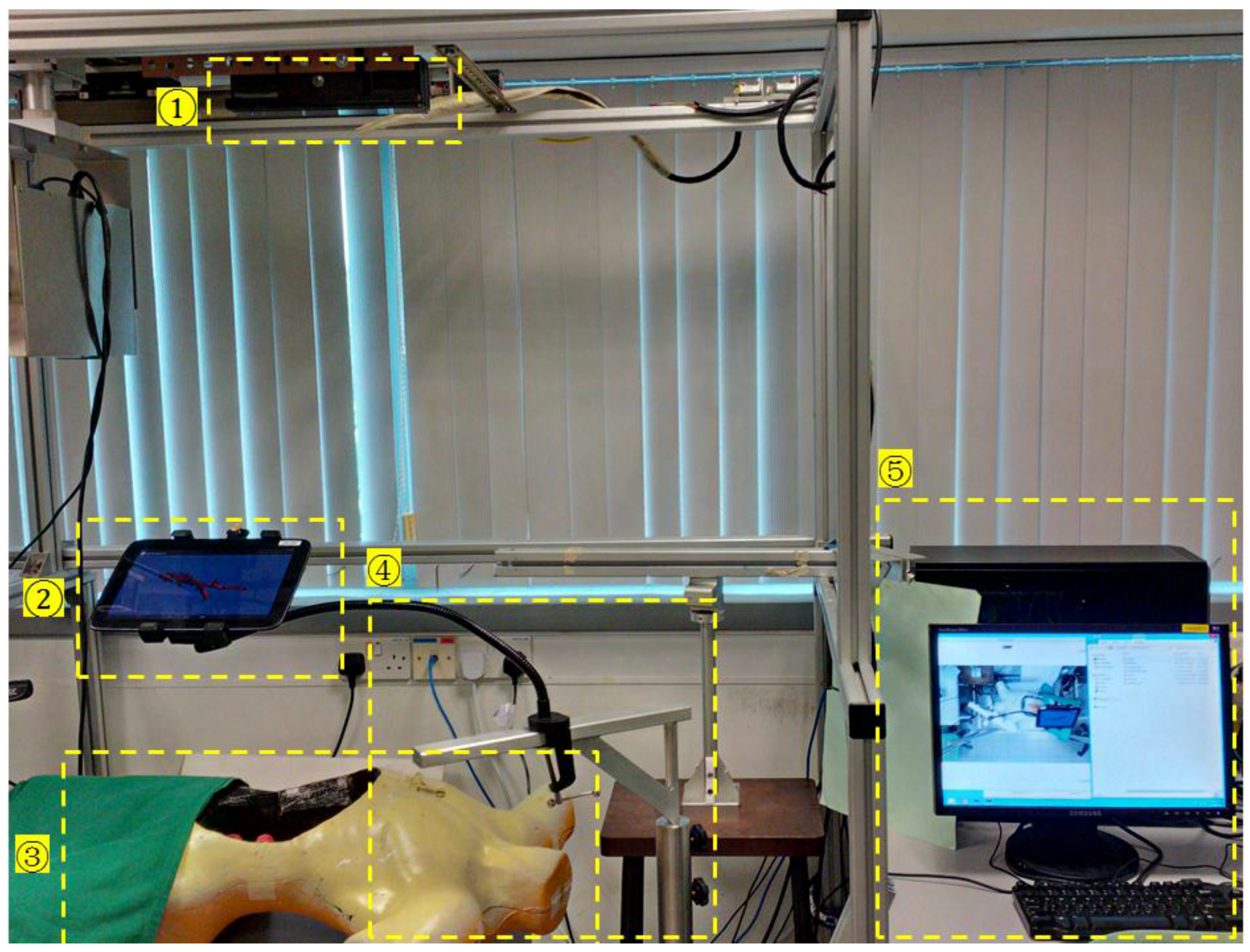
Figure 2.
Robotic system for voice microsurgery.

Figure 3.
System structures and work flow of the tablet based mobile augmented reality (AR) guidance.
Figure 3.
System structures and work flow of the tablet based mobile augmented reality (AR) guidance.

Figure 4.
Registration between point cloud and 3D model. (a) Point cloud generated from multimodality data sets: the point cloud of seventh degree implicit polynomials (IP) (yellow) generated from the source model (red) of the mannequin, and the point cloud acquired from the Kinect (green). (b) Registered surface with multimodality data sets.

Figure 5.
Work flow of feature detection and the matching process.

Figure 6.
Geometric model of tablet AR pose estimation. p1, p2; p3 and p4 are the corresponding points of P1, P2, P3 and P4 and on the object in physical world.
Figure 6.
Geometric model of tablet AR pose estimation. p1, p2; p3 and p4 are the corresponding points of P1, P2, P3 and P4 and on the object in physical world.

Figure 7.
3D touch interaction with an AR object.

Figure 8.
Depth image of the surgical field. (1) Tablet (2) Hand motion (3) Surgical tool (a radiofrequency (RF) ablation needle).
Figure 8.
Depth image of the surgical field. (1) Tablet (2) Hand motion (3) Surgical tool (a radiofrequency (RF) ablation needle).

Figure 9.
AR system test on a setup for vocal fold microsurgery with a 3D trachea model overlaid on a mannequin patient. (a) AR overview displaying both tablet view and the actual mannequin patient. (b) Screenshot of the tablet screen that augmented the patient with the trachea model. (c) Repositioning of the tablet for a side view of the patient.
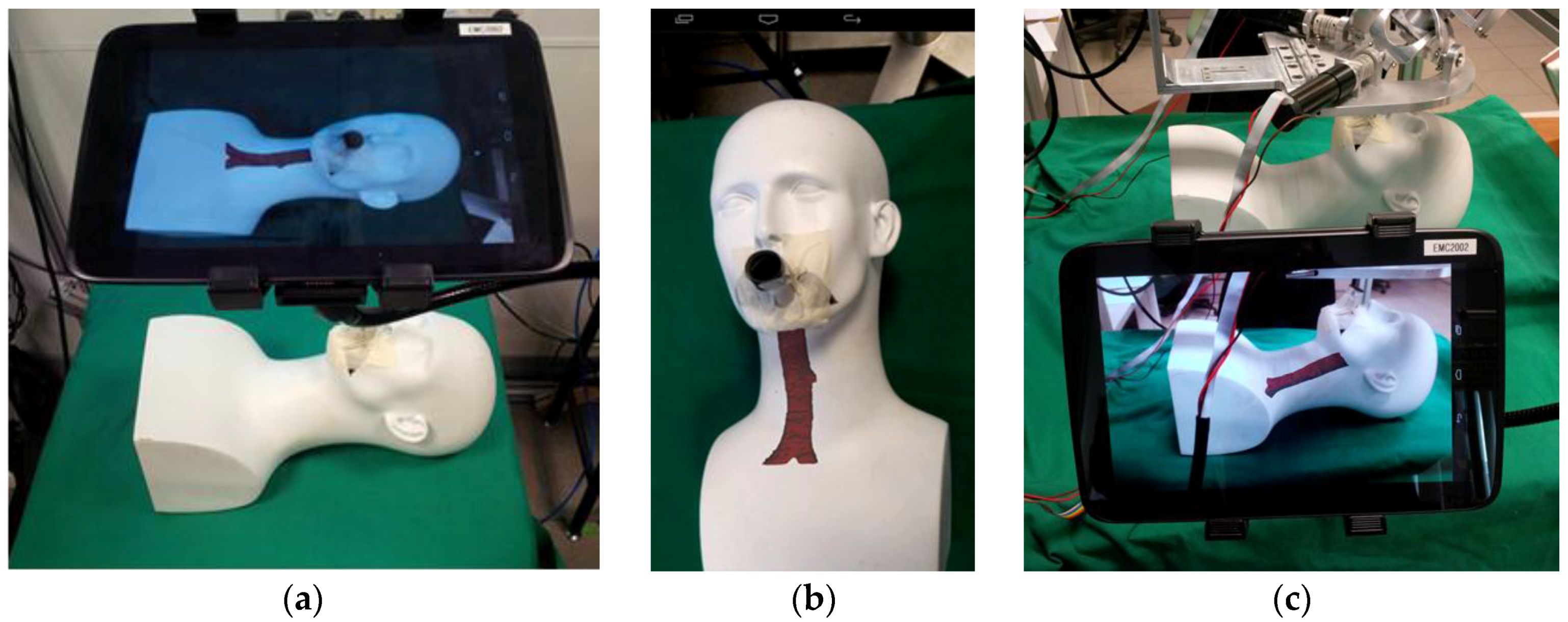
Figure 10.
Camera attachment for image quality and field of view enhancement. (a) Camera attachment setup on a tablet computer. (b) Test of feature points tracking and update in continuous frames of simulated vocal fold motion from a video recording.
Figure 10.
Camera attachment for image quality and field of view enhancement. (a) Camera attachment setup on a tablet computer. (b) Test of feature points tracking and update in continuous frames of simulated vocal fold motion from a video recording.

Figure 11.
Registration of 3D models with their corresponding objects in the physical world. Four virtual 3D models (white) were overlaid on their corresponding plasticine models (red) inside the mannequin.
Figure 11.
Registration of 3D models with their corresponding objects in the physical world. Four virtual 3D models (white) were overlaid on their corresponding plasticine models (red) inside the mannequin.
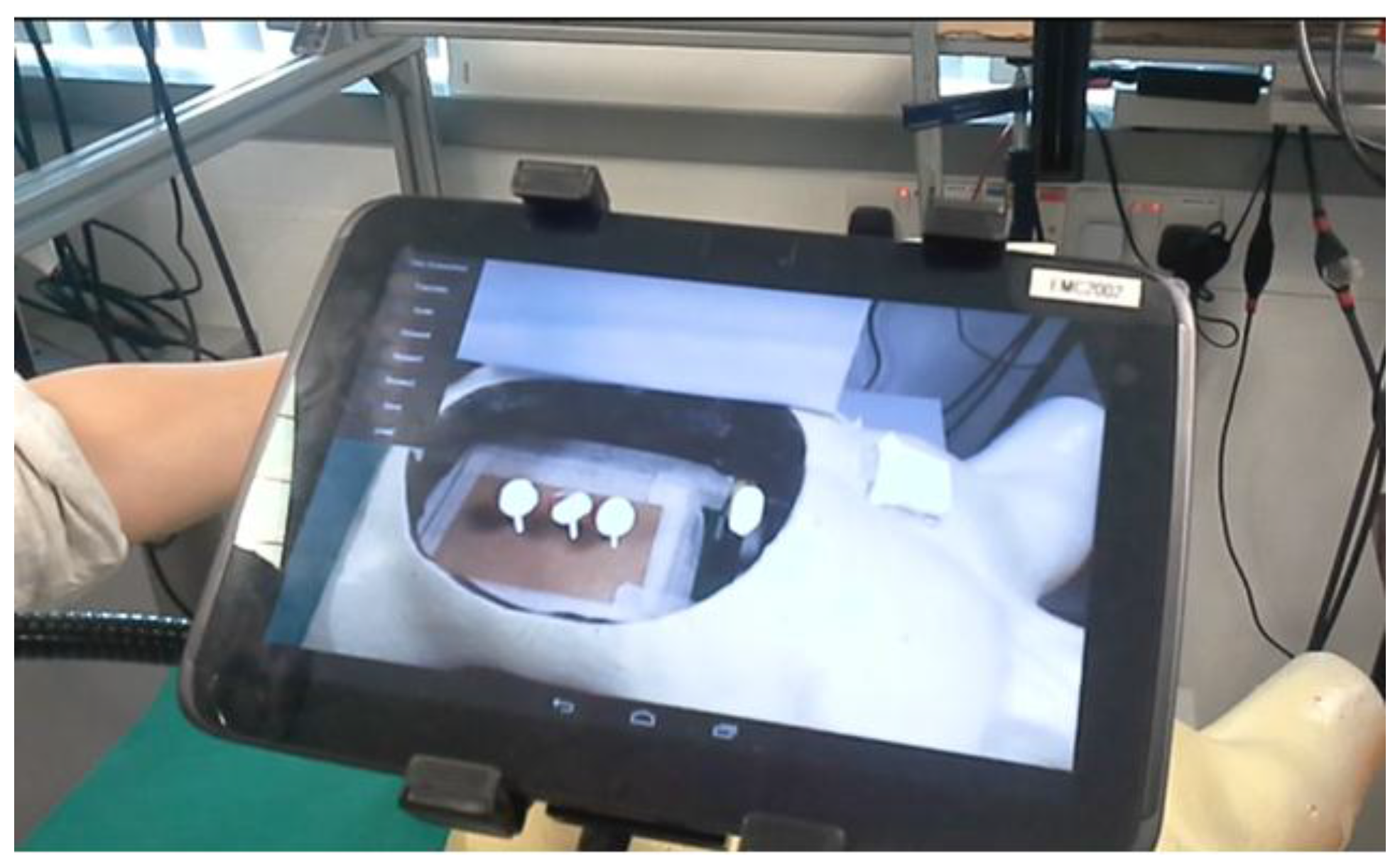
Figure 12.
Overlaying of hybrid multimodality data sets on the mannequin. (a) The image registered with one of the plasticine models. (b) Computed tomography (CT) slices being reviewed and selected by surgeons for intraoperative image reference. Specific areas of interest in red were marked onto the selected image.

Figure 13.
Multimodality augmented image guidance with a CT image and a 3D model for needle insertion. Different color-marked (green, red, pink) cone volumes represented the safety working spaces at different depth scale.
Figure 13.
Multimodality augmented image guidance with a CT image and a 3D model for needle insertion. Different color-marked (green, red, pink) cone volumes represented the safety working spaces at different depth scale.

Figure 14.
Mobile AR guidance errors that were produced by needle insertion tests. The center is the target point in the plasticine model, and the numbers around the circles are used to differentiate errors in orientation.
Figure 14.
Mobile AR guidance errors that were produced by needle insertion tests. The center is the target point in the plasticine model, and the numbers around the circles are used to differentiate errors in orientation.

Figure 15.
System setup in an operation room. (a) An in situ AR environment construction, (b) A preliminary system test in a real surgical environment.
Figure 15.
System setup in an operation room. (a) An in situ AR environment construction, (b) A preliminary system test in a real surgical environment.
© 2017 by the authors. Licensee MDPI, Basel, Switzerland. This article is an open access article distributed under the terms and conditions of the Creative Commons Attribution (CC BY) license (http://creativecommons.org/licenses/by/4.0/).
Share and Cite
MDPI and ACS Style
Wen, R.; Chng, C.-B.; Chui, C.-K. Augmented Reality Guidance with Multimodality Imaging Data and Depth-Perceived Interaction for Robot-Assisted Surgery. Robotics 2017, 6, 13. https://doi.org/10.3390/robotics6020013
AMA Style
Wen R, Chng C-B, Chui C-K. Augmented Reality Guidance with Multimodality Imaging Data and Depth-Perceived Interaction for Robot-Assisted Surgery. Robotics. 2017; 6(2):13. https://doi.org/10.3390/robotics6020013
Chicago/Turabian StyleWen, Rong, Chin-Boon Chng, and Chee-Kong Chui. 2017. "Augmented Reality Guidance with Multimodality Imaging Data and Depth-Perceived Interaction for Robot-Assisted Surgery" Robotics 6, no. 2: 13. https://doi.org/10.3390/robotics6020013
Note that from the first issue of 2016, this journal uses article numbers instead of page numbers. See further details here.