A Novel Docking System for Modular Self-Reconfigurable Robots

1
Division of Biomedical Engineering, University of Saskatchewan, Saskatoon, SK S7N 5A9, Canada
2
School of Mechatronics and Automation, Shanghai University, Shanghai 200444, China
3
Department of Mechanical Engineering, University of Saskatchewan, Saskatoon, SK S7N 5A9, Canada
*
Author to whom correspondence should be addressed.
Robotics 2017, 6(4), 25; https://doi.org/10.3390/robotics6040025
Submission received: 2 September 2017
/
Revised: 3 October 2017
/
Accepted: 9 October 2017
/
Published: 10 October 2017
(This article belongs to the Special Issue Robust and Resilient Robots)
Abstract
:Existing self-reconfigurable robots achieve connections and disconnections by a separate drive of the docking system. In this paper, we present a new docking system with which the connections and disconnections are driven by locomotion actuators, without the need for a separate drive, which reduces the weight and the complexity of the modules. This self-reconfigurable robot consists of two types of fundamental modules, i.e., active and passive modules. By the docking system, two types of connections are formed with the fundamental modules, and the docking and undocking actions are achieved through simple control with less sensory feedback. This paper describes the design of the robotic modules, the docking system, the docking process, and the docking force analysis. An experiment is performed to demonstrate the self-reconfigurable robot with the docking system.
1. Introduction
Self-reconfigurable robots are a class of robots that are composed of a set of modules that can control physical connections among modules and change their configuration. These robots are suitable for applications in unknown environments where robots may be required to change their configurations to meet the demands of a specific task. Particularly in planetary exploration, the robotic systems are desirable to be cost-effective, for example, to employ a single robot that is capable of performing different tasks such as assembling and carrying objects, and recovering its original function after partial damage.
There is a large number of researches in self-reconfigurable robotic systems, particularly in homogeneous systems that consist of identical active modules with actuators, connection systems, sensors, controllers, and effectors [1,2,3,4,5,6]. A recent survey paper is found in [7]. In contrast, there are fewer studies on heterogeneous self-reconfigurable robots [8,9,10]. Odin robot [8] consists of active links and active joints, in which the active links provide power and structure functionalities, and the active joints transfer the power and information between any adjacent links. ICubes robot [9] uses a manipulator composed of rigid links and active joints to move passive cubes around. Morpho robot [10] consists of passive and active modules and connectors, in which the passive modules function as linear joints, and they are specified for contraction and extension only. However, the existing heterogeneous systems are specified for a certain task, and it is insufficient to achieve an arbitrary configuration change.
To realize self-reconfigurability, an effective connection system for locking and releasing modules is crucial. Numerous connection systems for self-reconfigurable robots have been developed [7,11,12,13]. The most common connections are mechanical connections and magnetic connections. Mechanical connection systems enable strong connections. A motor or other form of actuating element, such as a shape memory alloy (SMA), is used to mate posts with latches, or mate holes with grooves. PolyBot robot [2] and CONRO robot [3,14] use peg-and-latch connection systems, in which a peg male part is inserted into the female part, and then a latch falls to lock the connection, and the connection is released when the shape memory actuators (SMAs) are heated. Crystalline robot [15] uses a rack-and-pinion mechanism to actuate the expansion and contraction of the faces. Each face of the module has a part of a connection mechanism. Two out of the four faces have active latches mechanisms, and the other two have passive channels. The module with faces that actively make the connection are called active, and the one that allows themselves to be connected are called passive. Similarly, ICubes robot [16] uses a key-lock connection mechanism, where the key inserts into a hole and rotates, and then is fixed into the locked position. The detachment action is carried out in reverse order. Another design is to change the peg or key into an active hook, and the robot uses a hook mechanism to achieve connection and disconnection, such as ATRON robot [17].
In magnetic connection systems, two surfaces are engaged by the attractive force between two magnets. In the M-TRAN robot [18], each module’s faces have polarity, and two connected faces have different polarity to connect. Disconnection of two surfaces was achieved by using SMA coils that, when heated, apply a strong pulling force to overcome the strength of the magnets. Another method of disconnecting two permanent magnet connectors, as applied to the SMORES platform [19], is to insert a docking key system into the connected modules’ docking port, holding it in place, while rotating its connector to separate the two magnets. This disconnection is much faster than the SMA approach. The locking actions for magnetic connection systems are relatively simple but the connection is not strong, and it may be disconnected by accident. As well, it consumes a relatively large amount of energy and it needs an actuation mechanism for detachment, which is usually more complex and increases the weight and energy consumption.
Another issue is that most connection systems have an independent power source for connection and disconnection only, which is designed at the cost of size, weight, and energy consumption. To overcome these disadvantages, this paper presents a novel key-lock docking system. Unlike the key-lock docking system in ICubes robot [16] that have only one locked position, the “key” of our docking system can have two statuses: (1) the “key” has relative motion with the “lock”, thus forming a passive joint; (2) the “key” can be locked at different positions in the “lock”. Another advantage of this docking system is that the reconfiguration (i.e., connections and disconnections) shares the same motor with the locomotion, rather than using a separate drive. Thus, the cost of the system is reduced, and the whole system has a relatively low energy consumption. To the authors’ best understanding, this study is the first time to integrate passive joints in a self-reconfigurable robot and to use the same drive for locomotion and reconfiguration in a self-reconfigurable robot. The concept of this key-lock docking system was originally proposed in our previous work [20], which was used for a resilient robot. The present paper will further analyze the detailed design of the docking system, docking process, docking forces, and how it achieves the self-reconfigurability for a self-reconfigurable robot.
2. Module Design and Docking Process
2.1. Module Design
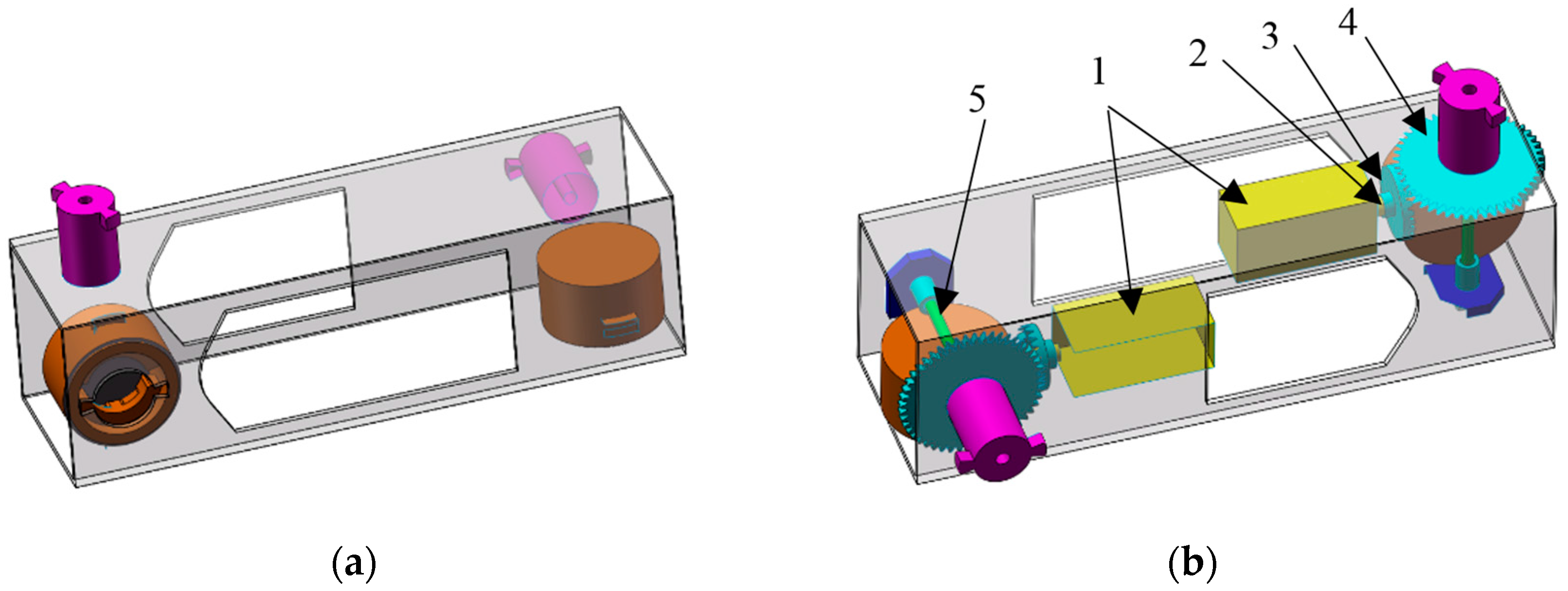
The robotic system consists of two types of fundamental modules, i.e., active modules and passive modules. An active module is a module that consists of actuators, sensors, and docking systems and is used for actuation. The active modules could provide actuation for locomotion and connections/disconnections. A passive module is a module that contains only docking system without any electronic devices. As shown in Figure 1, both active and passive modules are cuboids. All of the modules are structured to have two pairs of docking systems on each of the four sides. Each active module has two servomotors, which are the power supply of all movements, such as locomotion and reconfiguration. The output power of the motor is transmitted to the two male interfaces via two gears to an output axis.
2.2. Docking System
The docking system is designed based on a simple key-lock concept. Each docking system has a male interface (key part) and a female interface (lock part), and each module is structured to have two male interfaces and two female interfaces on each of its four sides, as shown in Figure 2. The male interface has two bits that engage the docking mechanism of any female interface of another module. The female interface has several layers that are spring-driven to achieve different types of connections.
Both linear motions and rotation motions are required to connect a female interface and a male interface, see Figure 2. To connect a pair of the docking system, the male interface of one module is engaged to either Layer 1 or Layer 2 of the female interface of another module, along Slot 1. To release, the male interface is driven to this slot and is released to disengage with the female interface.
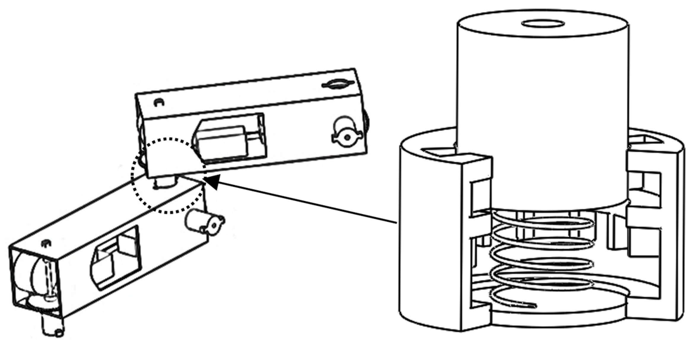
When a male interface inserts along Slot 1 and rotates to Layer 1 of a female interface and released, the two interfaces are connected to form a passive joint, see Figure 3. A passive joint is a type of connection formed by two modules, which generates a connection with the relative motion. When the male interface is rotated to Slot 1 and released, the passive joint is disconnected. It is noted that there are Velcro male side on Slot 1 and 2 to prevent the male interface from accidentally slipping out of Layer 1 if the bits of the male interface are aligned with the slots, see Figure 2.
When a male interface is pushed along Slot 2 and rotated, it will be spring-backed to the position between two teeth, and the two modules are locked and becomes a rigid link, see Figure 4. The length of the new link can be adjusted by changing the relative angle between two modules, i.e., unlocking the connections (i.e., pushing the male port to the bottom of the female interface) and then locking the connection (i.e., releasing when the male interface is rotated between another two teeth).
The adjustable length of a link formed by two modules is represented by a shadowed box in Figure 4a,b. The adjustable connection can be disassembled by rotating the male interface to Slot 2 and then rotating to Slot 1 and then releasing the male interface.
2.3. Docking Process
Since there are active joints, passive joints, and links, and all of the modules can connect with each other to achieve configuration changes, this robot is called underactuated self-reconfigurable robot. The architecture of the underactuated self-reconfigurable robot is as follows:
- An underactuated self-reconfigurable robot consists of two types of modules: joints and links. Further, joints are divided into active joints and passive joints. A link is formed by two modules with a fixed connection.
- The active and passive modules are the fundamental parts, and they are not disassembled.
- robot changes its configuration through a serial of docking actions between two modules, i.e., locking (forming a fixed connection) and unlocking (forming a passive joint), and disconnection (separation).
- The male interfaces of active modules provide actuation for both locomotion and reconfiguration.
- Docking and undocking need both linear and rotation motions and are driven by active modules in a closed-loop chain. If the male interface module is active, the rotation motion for docking can be driven by the male interface directly.
Reconfiguration is performed by connecting two branches (i.e., two branches forming a closed-loop), and disconnecting the closed-loop, as shown in Figure 5. Each branch should be a feasible branch in which a passive joint’s adjacent joint is not a passive joint. Thus, the passive joints are manipulated by their neighboring active joints. When neither branch is feasible to move to the other due to geometry or gravity, a third feasible branch will pick up one module and connect with another module.
An alternative reconfiguration approach is to switch a fixed connection into a passive joint, thus increasing the degree of freedoms (DOFs) of the chain. Figure 5 demonstrates the reconfiguration process of a robot with the following sequences:
- (1)
- Two branches are connected to form a closed-loop chain, and the junction forms a passive joint.
- (2)
- One connection of the two modules that will be separate in the next step is unlocked and become a passive joint. As needed, the fixed connection can be switched to passive joints to increase the DOF of the chain.
- (3)
- The connection in step (1) is locked.
- (4)
- The passive joint formed in step (2) is disconnected.
Note that the formation of passive joints formed in step (1) and (2) may be unnecessary if the DOF of the closed-loop chain is sufficient to complete a target disconnection. For example, if the required DOF in the closed-loop chain is satisfied, the connection in step (1) could become a locked connection directly, instead of passive joints. Thus, step (3) could be skipped. Similarly, step (2) could be skipped. Thus, two modules are disconnected directly in step (4).
3. Docking Force
Connecting a male interface and a female interface requires linear motions and rotation motions. The rotation motions are driven by the male interface directly, while the linear motion is actuated by the neighboring active modules. Because of the layered design of the female interface, linear motion does not need sensory feedback as long as the male interface is located in the slot. For example, to form a passive joint, after the male interface is guided into Slot 1 of the female interface, the subsequent motion with any displacement or any force is feasible, and it does not need any sensory feedback. The design of the female interface may be viewed as poke yoke design, which allows the entire system to require less sensory feedback and simple control.
In the following, we mainly analyzed the limits of force and torque, so as to achieve the corresponding linear and rotation motion. Here, we assume that one interface moves while the other one is fixed. There are two situations: (1) The male interface is pushed or rotated inside a female interface, while the female interface is fixed. Here, the rotation is achieved by the male interface directly, and the remaining movements are actuated by the neighboring active modules; (2) The female interface is pushed or rotated when the male interface is fixed inside of the female interface. Here, all of the movements are actuated by the neighboring active modules.
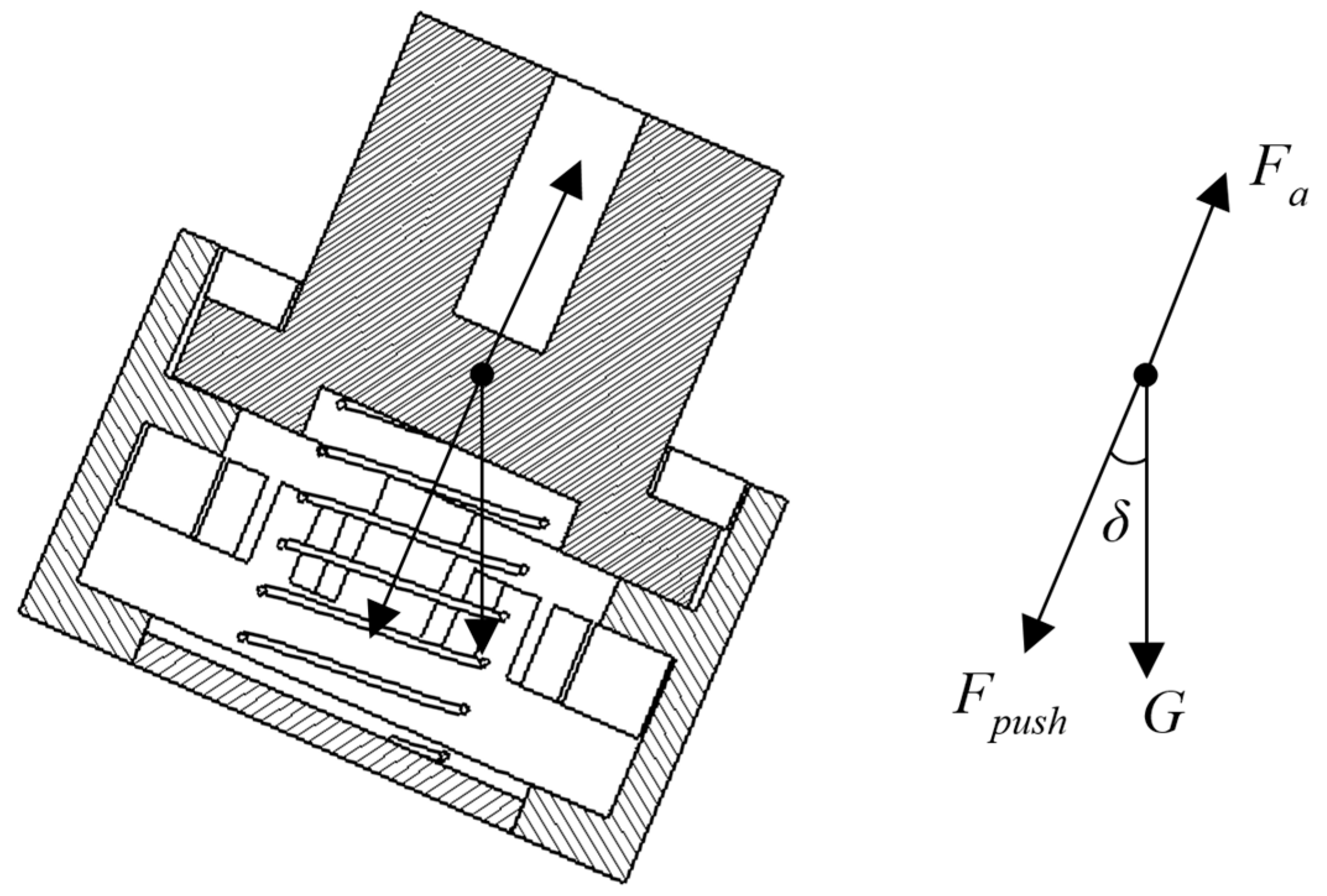
Figure 6 illustrates a passive joint in which the male interface locates in Layer 2 of the female interface. When the male interface pushes into the female interface axially, the spring creates the axial force Fa through the male interface. Therefore, the required push force is:
where G is the mass of the gravity of the male interface, Fa = kLbit, k is the spring constant, Lbit is the height of the bit of the male interface. δ is the angle between the direction of the vertical axis and that of the resultant force, see Figure 6.
Fpush = kLbit − Gcosδ
As the docking system uses the thermoplastic material, the bit of the male interface may be broken if the shear stress reaches or exceeds the ultimate strength. Therefore, the maximal push force Fmax is
where A is the cross-sectional area of the bit of the male interface, see Figure 7a. L0 is the maximal spring compression in Layer 1, i.e., the height of this layer. τ is the shear stress of the material.
Fmax = 2Aτ + Gcosδ − kLbit
To form a passive joint, the male interface rotates in Layer 1 of the female interface, and the bit develops friction f, see Figure 7b.
where μ is the coefficient of friction.
f = μ (k Lbit − Gcosδ)
Therefore, the minimum torque overcoming the friction is as follows:
where Mf is the minimum torque, and R is the radius of the bit.
Mf = 2fR
For a fixed connection, the minimum push force Fp is
where the spring free length is L, which is the length from Layer 1 to the bottom of the female interface.
Fp = kL − Gcosδ
In Layer 2, the minimum torque required to rotate the male interface into one pair of teeth is as follows:
Mf = 2μkLR
The bits are locked when the male interface locates between two teeth. The locking force exerted by the spring is:
Flock = kL − Gcosδ
In case the shear stress generated by the spring force reaches or exceeds the ultimate strength, the maximum spring constant kmax is as follows:
where L0 is the length from Layer 1 to the top of the teeth in Layer 2.
kmax = (2Aτ + Gcosδ)/(L0 + Lbit)
4. Hardware Implementation
4.1. Hardware
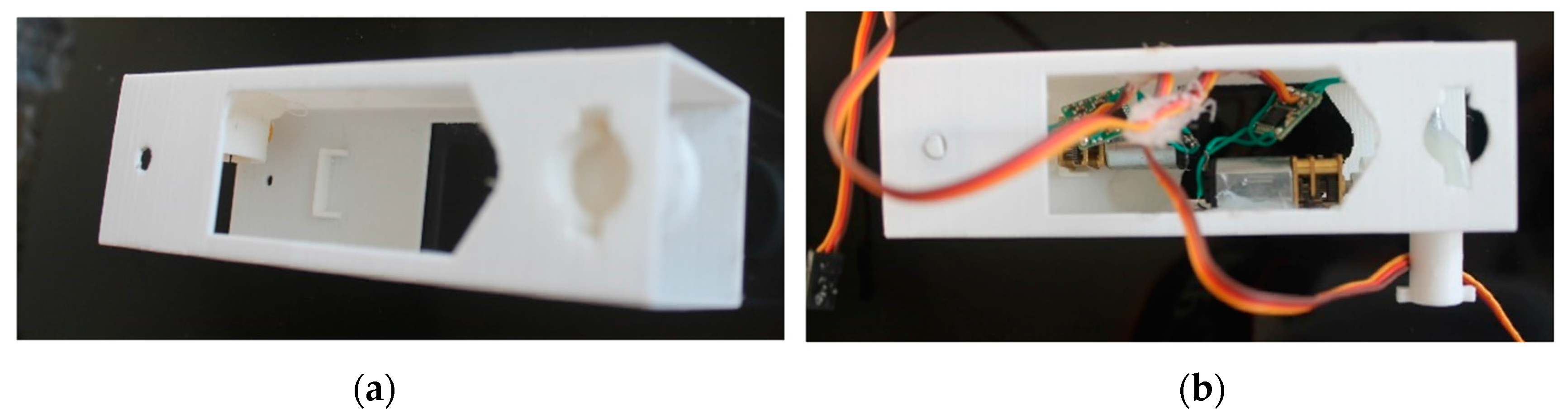
The designs given in Section 2 were implemented using plastic modules assembled with electrical components. The mechanical components, such as gears, shafts, and docking systems are created using PLA with MakerBot Replicator 2 printing machine. Files generated by Solidworks were sent to the three-dimensional (3D) printer for creating components that require minimal assembly. The printer’s resolution is 0.1 mm. The design of the modules is modeled using Solidworks. Figure 8 shows a passive module and an active module. The length, width, and height of modules are taken as 11 cm, 3.2 cm, and 3.2 cm, respectively. Actuation of the gear mechanism is provided by small servos, which are capable of providing a torque of 1.5 kg-cm at 6 volts. An active module with two servos and two pairs of docking systems, complete with shafts, gears measures approximately 200 gr, and a passive module with two pairs of docking system measures approximately 100 gr. It is noted that the spring is replaced by a rubber band and the Velcro male side on the two Slots was removed due to manufacturing difficulties. In order to reduce the complexity of the connection, we used the female interfaces from active modules or passive modules, but we only used the male interfaces of active modules as these male interfaces can directly complete the rotation action. The linear action is actuated by the neighboring active module drivers. Therefore, in the experiment, the passive module has only two female interface modules, see Figure 8a.
4.2. Experiment
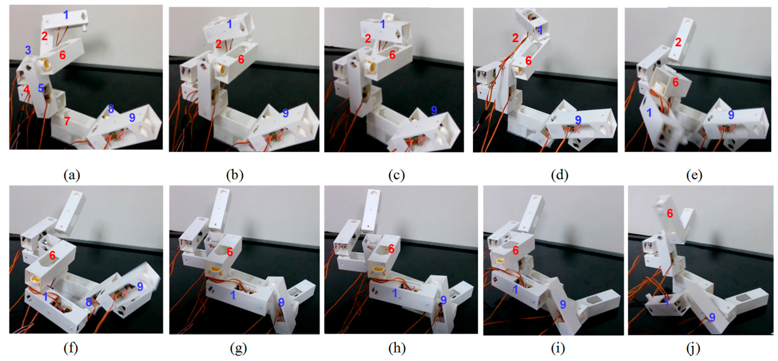
The prototypes described above are used to test the ability of reconfiguration of the system on a platform. These tests are carried out to show that the modules are capable of achieving undocking, docking, and disconnection actions. Figure 9 shows the reconfiguration process of a robotic structure, that is, Module 6 picks up Module 1 and connects to Module 9. The robotic structure consists of four passive modules (Modules 2, 4, 6, 7, marked in red) and five active modules (Modules 1, 3, 5, 8, 9, marked in blue).
As seen in the series of pictures in Figure 9, Module 6 “picks up” Module 1 and connects Module 1 with Module 9. First, driven by Module 3, Module 1 moves to Module 6 (Figure 9b), and forms a passive joint (Figure 9c), driven by Module 3 and Module 1. The connection between Module 1 and Module 2 becomes a passive joint, driven by Module 3 and Module 1 (Figure 9d). Module 1 and Module 2 are disconnected, driven by Module 1 and Module 5 (Figure 9e). Then, driven by Module 8, Module 9 moves to Module 1 (Figure 9f) and forms a passive joint driven by Module 8 and Module 1 (Figure 9h). Driven by Module 1 and Module 9, the connection between Module 1 and Module 6 becomes a passive joint (Figure 9i). Module 1 and Module 6 are disconnected, and driven by Module 1 and Module 9 (Figure 9j). The link to this video is https://m.youtube.com/watch?v=oxxjNu0kRO4.
Five runs were made to demonstrate the reconfiguration process. The average speed is approximately two minutes for docking and one and a half minutes for undocking. The modules are powered by an external power supply and controlled by the program through a PC. The whole reconfiguration took about ten minutes. The experiment demonstrated that the performance of the robot is good.
During the reconfiguration, no fixed connection is formed, i.e., no module was locked. The passive joint formation is seen in Figure 9c,d,h,i. As the module prototypes weigh less, that is, the gravity does not overcome the forces generated by the spring in the female interface, the passive joint does not have a free swing motion, but it still has a relative motion in a closed-loop chain with a driving force. As well, the modules were bent slightly due to the poor physical properties of the plastic material used in the experiment. However, these errors can be minimized by using a material with better physical properties.
5. Conclusions
In this paper, we presented a novel docking system for self-reconfigurable robots. With the docking system, the minimum number of fundamental modules (i.e., active and passive modules) is needed, thus to increase the overall resource utilization as well as to reduce the cost.
Based on the docking system, passive joints and fixed connections are formed with the fundamental modules. The reconfiguration and locomotion share the same drive. Although the proposed docking system has relatively lower accuracy due to shared drive, it leads to other advantages, such as a simple connection and disconnection mechanism, smaller size, lower cost, etc. Due to the passive joints and rigid links, the energy consumption in locomotion is reduced when compared with the existing self-reconfigurable robots. During the reconfiguration process, the rotation motion is directly actuated by the male interface, while the linear motion is actuated by the neighboring active modules, but it does not require precise displacement and force. As a result, the reconfiguration complexity is reduced, resulting in a reduction of energy consumption. Also, the docking actions are achieved by using a simple control with less sensory feedback due to the layered design for the female interface.
Besides, the inclusion of passive joints and fixed connections provides an effective approach to deal with the following failures: an active joint is unlocked and becomes a passive joint; an active joint is locked and becomes a fixed connection. This feature, that is, the failure of active modules may simply change the role of the modules instead of rendering the system completely useless, is a novel feature of the robotic system, and it will increase the degree of the resilience of the robot [20].
There are, however, some issues that remain to be investigated considering the manufacturing difficulties. We are working on the improvement of the modules and docking systems by using metal material, and the modules will be stiff to reduce errors. We intend to install microcontroller and sensors on each unit. In the present paper, to reduce the complexity of the reconfiguration, we have not considered the passive docking that is formed by a male interface from a passive module and a female interface from any other module, and this will be included in our next step. Also, we will consider more dynamic aspects of the whole system. Furthermore, the controller used for the robot in this paper is all centralized off-line, and our next step is to control the underactuated self-reconfigurable robot online using deep reinforcement learning method. We will investigate the influence of the design parameter, such as the dimension of the modules and spring constants, based on a quantitative analysis in energy-consumption, time-consumption, and accuracy-loss, in order to achieve a good balance between acceptable accuracy and real-time processing/energy-consumption for reconfiguration and locomotion.
Acknowledgments
The author (W.J. Zhang) wants to acknowledge a partial financial support to his involvement from NSF of China (No. 51375166) and NSERC Discovery Grant.
Author Contributions
Tan Zhang, Wenjun Zhang and Madan Gupta conceived and designed the testbed; Tan Zhang implemented the testbed and performed the experiments; Tan Zhang and Wenjun Zhang analyzed the data; Tan Zhang, Wenjun Zhang and Madan Gupta wrote the paper.
Conflicts of Interest
The authors declare no conflict of interest.
References
- Yim, M.; Shen, W.M.; Salemi, B.; Rus, D.; Moll, M.; Lipson, H. Modular self-reconfigurable robot systems—Challenges and opportunities for the future. IEEE Robot. Autom. Mag. 2007, 14, 43–52. [Google Scholar] [CrossRef]
- Yim, M.; Zhang, Y.; Roufas, K.; Duff, D.; Eldershaw, C. Connecting and disconnecting for chain self-reconfiguration with PolyBot. IEEE ASME Trans. Mechatron. 2002, 7, 442–451. [Google Scholar] [CrossRef]
- Castano, A.; Shen, W.M.; Will, P. CONRO: Towards Deployable Robots with Inter-Robots Metamorphic Capabilities. Auton. Robots 2000, 8, 309–324. [Google Scholar] [CrossRef]
- Kurokawa, H.; Tomita, K.; Kamimura, A.; Kokaji, S.; Hasuo, T.; Murata, S. Distributed self-reconfiguration of M-TRAN III modular robotic system. Int. J. Robot. Res. 2008, 27, 373–386. [Google Scholar] [CrossRef]
- Zykov, V.; Mytilinaios, E.; Adams, B.; Lipson, H. Self-reproducing machines. Nature 2005, 435, 163–164. [Google Scholar] [CrossRef] [PubMed]
- Gilpin, K.; Kotay, K.; Rus, D.; Vasilescu, I. Miche: Modular shape formation by self-disassembly. Int. J. Robot. Res. 2008, 27, 345–372. [Google Scholar] [CrossRef]
- Chennareddy, S.; Agrawal, A.; Karuppiah, A. Modular Self-Reconfigurable Robotic Systems: A Survey on Hardware Architectures. J. Robot. 2017, 2017. [Google Scholar] [CrossRef]
- Garcia, R.; Stoy, K. The Odin Modular Robot: Electronics and Communication. Master’s Thesis, The Maersk Mc-Kinney Moller Institute, University of Southern Denmark, Odense, Denmark, 2008. [Google Scholar]
- Ünsal, C.; Kiliççöte, H.; Khosla, P.K. A modular self-reconfigurable bipartite robotic system: Implementation and motion planning. Auton. Robots 2001, 10, 23–40. [Google Scholar] [CrossRef]
- Yu, C.H.; Haller, K.; Ingber, D.; Nagpal, R. Morpho: A self-deformable modular robot inspired by cellular structure. In Proceedings of the IEEE/RSJ International Conference on Intelligent Robots and Systems, Nice, France, 22–26 September 2008; pp. 3571–3578. [Google Scholar]
- Støy, K.; Brandt, D.; Christensen, D.J. Self-Reconfigurable Robots: An Introduction; MIT Press: Cambridge, MA, USA, 2010. [Google Scholar]
- Plooij, M.; Mathijssen, G.; Cherelle, P.; Lefeber, D.; Vanderborght, B. Lock your robot: A review of locking devices in robotics. IEEE Robot. Autom. Mag. 2015, 22, 106–117. [Google Scholar] [CrossRef]
- Brunete, A.; Ranganath, A.; Segovia, S.; de Frutos, J.P.; Hernando, M.; Gambao, E. Current trends in reconfigurable modular robots design. Int. J. Adv. Robot. Syst. 2017, 14, 1–21. [Google Scholar] [CrossRef]
- Shen, W.M.; Will, P. Docking in self-reconfigurable robots. In Proceedings of the 2001 IEEE/RSJ International Conference on Intelligent Robots and Systems, Maui, HI, USA, 29 October–3 November 2001; pp. 1049–1054. [Google Scholar]
- Rus, D.; Vona, M. Crystalline robots: Self-reconfiguration with compressible unit modules. Auton. Robots 2001, 10, 107–124. [Google Scholar] [CrossRef]
- Unsal, C.; Khosla, P. Mechatronic design of a modular self-reconfiguring robotic system. In Proceedings of the IEEE International Conference on Robotics and Automation, San Francisco, CA, USA, 24–28 April 2000; pp. 1742–1747. [Google Scholar]
- Ostergaard, E.H.; Kassow, K.; Beck, R.; Lund, H.H. Design of the ATRON lattice-based self-reconfigurable robot. Auton. Robots 2006, 21, 165–183. [Google Scholar] [CrossRef]
- Murata, S.; Yoshida, E.; Kamimura, A.; Kurokawa, H.; Tomita, K.; Kokaji, S. M-TRAN: Self-reconfigurable modular robotic system. IEEE ASME Trans. Mechatron. 2002, 7, 431–441. [Google Scholar] [CrossRef]
- Davey, J.; Kwok, N.; Yim, M. Emulating self-reconfigurable robots-design of the SMORES system. In Proceedings of the 2012 IEEE/RSJ International Conference on Intelligent Robots and Systems (IROS), Vilamoura, Portugal, 7–12 October 2012; pp. 4464–4469. [Google Scholar]
- Zhang, T.; Zhang, D.; Gupta, M.M.; Zhang, W.J. Design of a General Resilient Robotic System Based on Axiomatic Design Theory. In Proceedings of the 2015 IEEE International Conference on Advanced Intelligent Mechatronics (AIM), Busan, South Korea, 7–11 July 2015; pp. 71–78. [Google Scholar]
Figure 1.
Passive and active modules (adapted from [20]). (a) The three-dimensional (3D) view of a passive module; (b) The 3D view of an active module: servomotor (1), transmission shaft (2), small gear (3), big gear (4), and output axis (5).
Figure 1.
Passive and active modules (adapted from [20]). (a) The three-dimensional (3D) view of a passive module; (b) The 3D view of an active module: servomotor (1), transmission shaft (2), small gear (3), big gear (4), and output axis (5).

Figure 2.
Docking system structure.
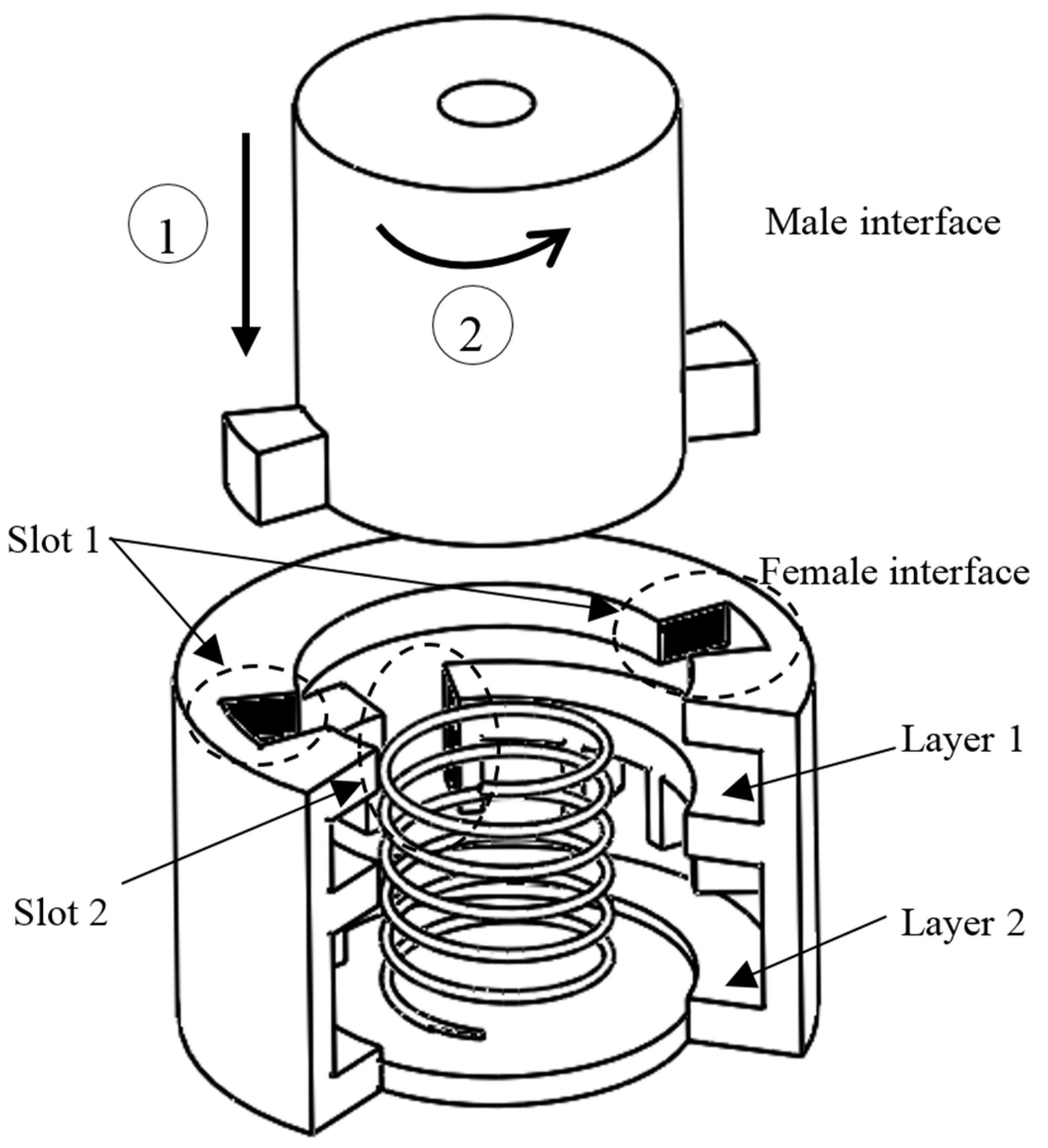
Figure 3.
A passive joint and a cross-sectional view of the docking system (adapted from [20]).
Figure 3.
A passive joint and a cross-sectional view of the docking system (adapted from [20]).

Figure 4.
A fixed connection between two modules and the cross-sectional view of the docking system (adapted from [20]). (a,b) show different states of the docking system with different angles, resulting in different lengths of the whole link which are represented by a shadowed box.
Figure 4.
A fixed connection between two modules and the cross-sectional view of the docking system (adapted from [20]). (a,b) show different states of the docking system with different angles, resulting in different lengths of the whole link which are represented by a shadowed box.
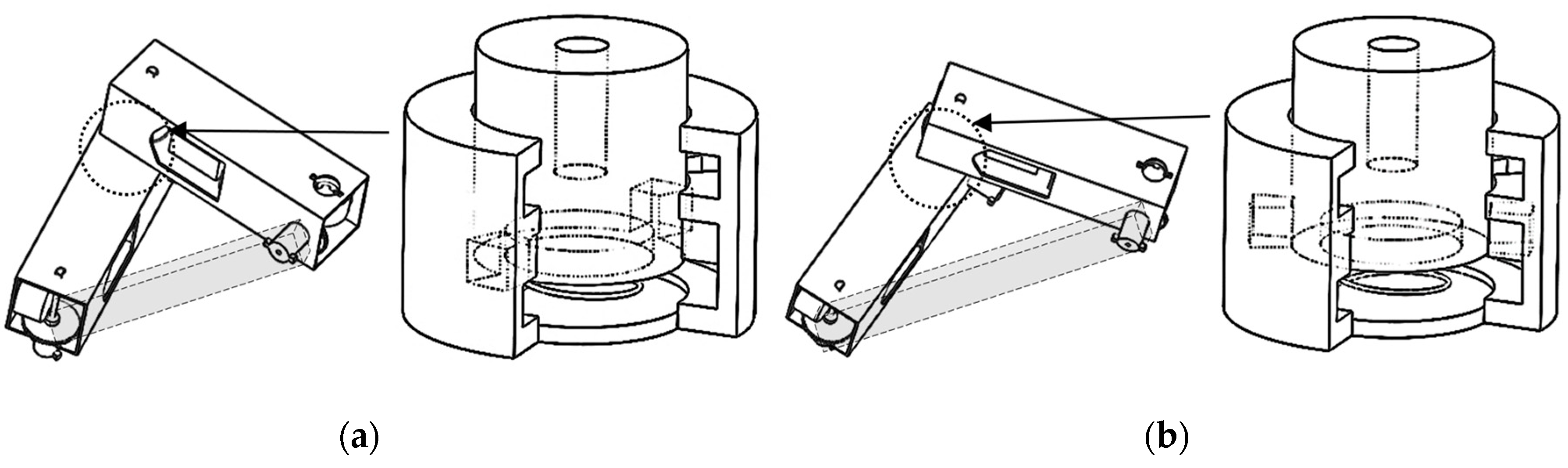
Figure 5.
The process of changing configuration. (a) initial configuration; (b) connecting two modules as passive connection; (c) unlocking the connection of the two modules that will be separate in the next step and change it into a passive one; (d) locking the passive joints formed in (b,e) disconnecting the passive joint formed in (c).
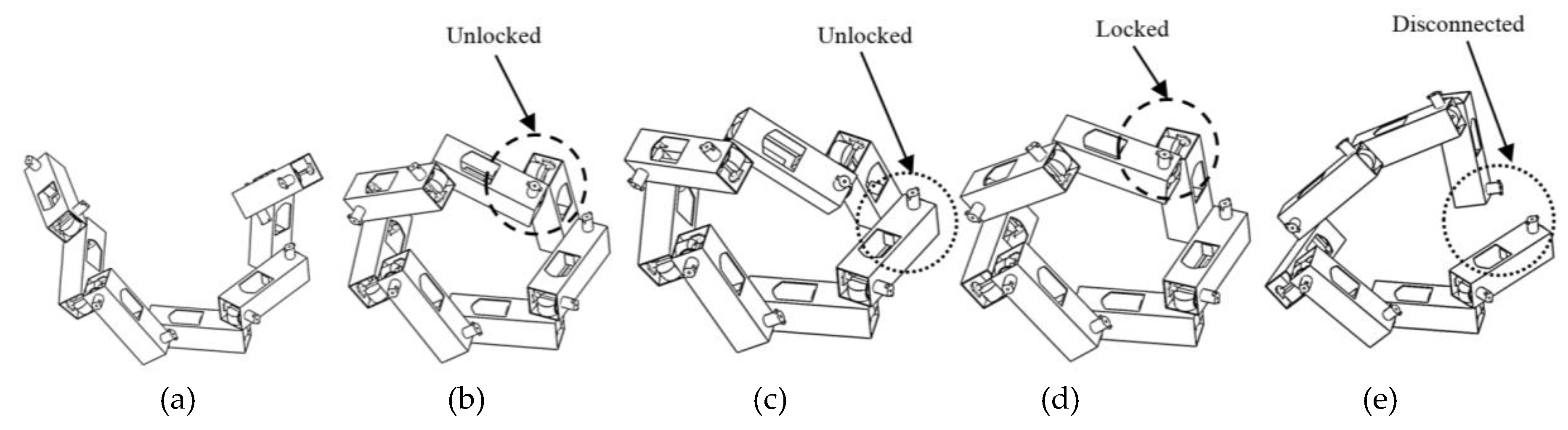
Figure 6.
Force reactions on the male interface for forming a passive joint.

Figure 7.
A cross-sectional area of a bit of a male interface (a), and a cross-sectional view of a passive joint (b).
Figure 7.
A cross-sectional area of a bit of a male interface (a), and a cross-sectional view of a passive joint (b).
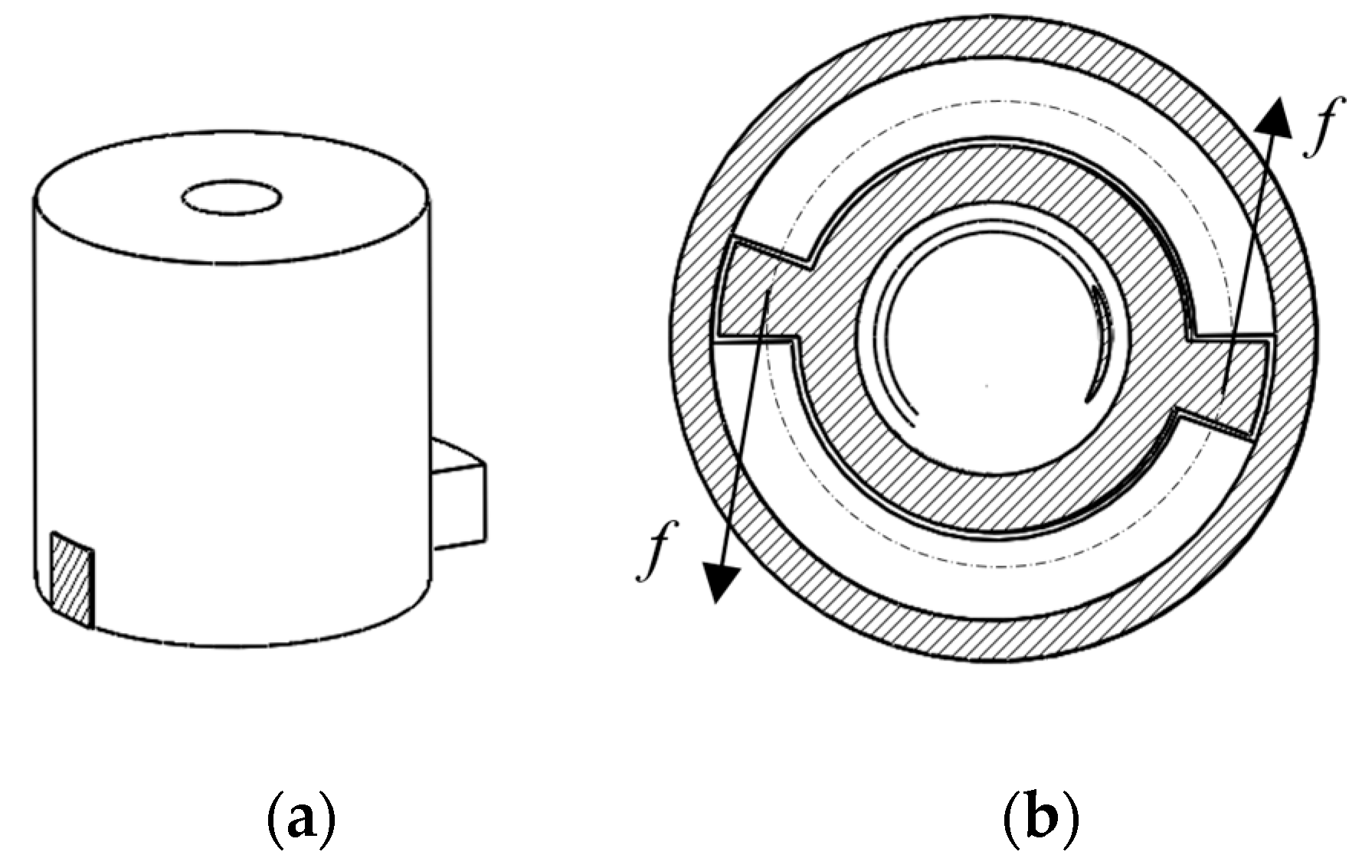
Figure 8.
The prototype of a passive module (a) and an active module (b).

Figure 9.
Self-reconfiguration process. (a) Original configuration; (b) Module 1 moves to Module 6; (c) Module 1 docks Module 6 and forms a passive joint; (d) the connection between Module 1 and Module 2 changes to passive joints; (e) Module 1 disconnects with Module 2; (f) Module 9 moves to Module 1; (g) Module 1 docks Module 9 and forms passive joint; (h) the connection between Module 6 and Module 1 becomes a passive joint; (i) Module 1 is released from Module 6; and, (j) Module 1 and Module 6 is disconnected.
© 2017 by the authors. Licensee MDPI, Basel, Switzerland. This article is an open access article distributed under the terms and conditions of the Creative Commons Attribution (CC BY) license (http://creativecommons.org/licenses/by/4.0/).
Share and Cite
MDPI and ACS Style
Zhang, T.; Zhang, W.; Gupta, M.M. A Novel Docking System for Modular Self-Reconfigurable Robots. Robotics 2017, 6, 25. https://doi.org/10.3390/robotics6040025
AMA Style
Zhang T, Zhang W, Gupta MM. A Novel Docking System for Modular Self-Reconfigurable Robots. Robotics. 2017; 6(4):25. https://doi.org/10.3390/robotics6040025
Chicago/Turabian StyleZhang, Tan, Wenjun Zhang, and Madan M. Gupta. 2017. "A Novel Docking System for Modular Self-Reconfigurable Robots" Robotics 6, no. 4: 25. https://doi.org/10.3390/robotics6040025
Note that from the first issue of 2016, this journal uses article numbers instead of page numbers. See further details here.