HexaMob—A Hybrid Modular Robotic Design for Implementing Biomimetic Structures


Birla Institute of Technology & Science (BITS) Pilani, K.K Birla Goa Campus, Goa, 403726, India
*
Author to whom correspondence should be addressed.
Robotics 2017, 6(4), 27; https://doi.org/10.3390/robotics6040027
Submission received: 27 July 2017
/
Revised: 11 October 2017
/
Accepted: 11 October 2017
/
Published: 16 October 2017
Abstract
:Modular robots are capable of forming primitive shapes such as lattice and chain structures with the additional flexibility of distributed sensing. The biomimetic structures developed using such modular units provides ease of replacement and reconfiguration in co-ordinated structures, transportation etc. in real life scenarios. Though the research in the employment of modular robotic units in formation of biological organisms is in the nascent stage, modular robotic units are already capable of forming such sophisticated structures. The modular robotic designs proposed so far in modular robotics research vary significantly in external structures, sensor-actuator mechanisms interfaces for docking and undocking, techniques for providing mobility, coordinated structures, locomotions etc. and each robotic design attempted to address various challenges faced in the domain of modular robotics by employing different strategies. This paper presents a novel modular wheeled robotic design - HexaMob facilitating four degrees of freedom (2 degrees for mobility and 2 degrees for structural reconfiguration) on a single module with minimal usage of sensor-actuator assemblies. The crucial features of modular robotics such as back-driving restriction, docking, and navigation are addressed in the process of HexaMob design. The proposed docking mechanism is enabled using vision sensor, enhancing the capabilities in docking as well as navigation in co-ordinated structures such as humanoid robots.
1. Introduction
Robotics is a rigorously researched domain for the development of automation technologies necessary for consumer and commercial requirements and this research is gaining prominence due to unique features facilitated by modular designs such as reconfigurability, higher reusability, low maintenance costs, numerous applications, and adaptability. Due to technological advancements, various robotic technologies are being employed in space exploration, automobiles, military surveillance and exploration, prosthetics, medical surgery and diagnosis, etc. Though significant advances have been made in research and prototyping of robots in these respective application domains, the robotic solutions are often application specific and their utilization is limited to a small subset of these domains. The restricted scope of such designs can be improvised by design and utilization of homogeneous modular units that suit multiple purposes. The research in modular robotics attempts to address these constraints by utilizing homogeneous robotic units with limited capabilities for the formation of coordinated structures [1,2].
The research in modular robotics is conventionally categorized using various parameters/features facilitated by individual robotic units such as structural formation capabilities, locomotion and form-factor. Table 1 provides a list of categories proposed so far based on the research in hardware modeling in the domain of modular robotics. Modular robotic units employ conventional actuators such as servo and DC motors for mobility and reconfiguration and the power consumption of such actuators increases during formation of 3D structures due to increase in loads. A powerless back-driving restriction mechanism at actuators is necessary for maintaining the 3D structures for long-term operation of robotic systems in practical scenarios. The docking interfaces featuring power-sharing and communication mechanisms along with provision for autonomous docking are also requirements for rapid reconfiguration. A survey provided in [3] on hardware architectures of modular robotics, a relative comparison on various reconfiguration features and structures of modular robots provided in [4] and an extensive survey including software components published in [5] provide deep insight into research in the domain of modular robotics.
CEBOT [6] robotic units were the first prototypes developed in the field of modular robots. The CEBOT robotic modules are heterogeneous units supporting mobility facilitating autonomous docking with each other for the formation of various lattice, chain, truss and free-form structures. Researchers subsequently explored numerous mechanisms for docking, mobility, reconfiguration, and locomotion for facilitating the autonomous functionality of robots by deriving inspiration from CEBOT. The robotic units depending on the design and hardware features can independently generate locomotion or implement locomotion and reconfiguration with the help of their environment or neighboring modular robots. Form-factor of the robotic units also plays a vital role in structural formations and sensor-actuator mechanisms enabling micro-sized robots to operate on electrostatic forces and macro-sized robots to operate on magnets and hooks in spite of maintaining the same outer skeleton structures.
Many robotic modules are later developed with capabilities for forming chain structures. Modular robotic designs such as ACM [7,8,9], Millibot [10], Uni-rover [11], Sambot [12], Scout [13,14] and Trimobot [15] are capable of forming chain structures along with mobility support. Robotic designs such as Polypod [16], CONRO [17], Polybot [18], Transmote [19], ModReD [20,21], and CKbot [22] are also capable of forming chain structures designed without self-mobility feature in independent robotic modules. Hybrid category robotic units such as ATRON [23,24], M3 robot [25], M3 Express [26], iMobot [27], SMORES [28], M-TRAN I-III [29,30,31], UBot [32], Soldercubes [33], HyMod [34] and CoSMO [35] are capable of forming both lattice and chain structures with few designs equipped with capabilities for self-mobility. Truss robotic units [36,37,38] employs telescopic links and variety of joints for forming reconfigurable structures. The free-form category robotic modules [39,40,41] are loosely linked to each other by means of weak magnetic forces and electrostatic forces.
The majority of modular robotic designs explored the concept of developing an immobile robot [33,42,43] which is coupled with homogeneous units for forming the coordinated structures. The major drawback of such systems is the requirement of manual intervention in most of the test scenarios. Few modular units are assembled manually to initiate locomotion and reconfiguration due to lack of aggregation and dispersion abilities [44]. The HexaMob robotic design proposed in this paper is a novel modular robotic design with mobility features capable of forming chain structures and aims at reducing human intervention to further lower levels by the employment of vision sensors. The majority of constraints in modular robotic designs such as autonomous docking and navigation are addressed in the design and details are provided in following sections.
2. Related Work
Numerous hybrid modular robotic designs were proposed and prototyped for analysis and research so far. The hybrid modular robotic designs are capable of forming chain along with lattice structures and seldom mimics biological structures like gaits and centipedes. The overall capabilities of hybrid modular robotic designs depend on the performance of autonomous capabilities, sensor-actuator interfaces, chassis structures and locomotion mechanisms. Few modular robots developed till date with capabilities of mobility are summarized below for outlining the hardware designs.
2.1. M3 & M3Express Modular Robot
M3 [25] modular robot is an L-shaped robot equipped with three wheels (one omnidirectional and two regular wheels) that are capable of supporting mobility as well as the formation of structures. Each wheel as shown in Figure 1a supports mobility and consists of sockets for docking with neighboring robotic modules. The wheels also aid in rotation and lifting after successful docking. M3 robotic module is prototyped in 2010 and it employs hooks for the sake of genderless docking. MExpress [26] prototyped in 2012 is morphologically similar to M robotic module and it employs internal magnets coupled with slip rings that control the position of magnets for docking and undocking.
2.2. iMobot
The iMobot [45] robotic module is an assembly of two semi-cylindrical structures as shown in Figure 1b comprising of six faces for docking of which two side faces can function as wheels for providing mobility to the robot. Numerous structures are possible with iMobot design due to its three degrees of freedom and multiple faces for manual latching. Authors demonstrated the platform capabilities in locomotion such as crawling, folding, standing and rolling. The absence of a back-driving restriction can be visualized as a drawback that leads to continuous power consumption in the iMobot design.
2.3. SMORES
SMORES [28] hybrid robotic module consists of a three-wheeled cuboid structure similar to M3 robot with four degrees of freedom. The front wheel apart from rotating can be lifted for generating pitch movement. Docking is facilitated and maintained by the magnets mounted on the wheels and undocking is facilitated by rotation of the wheels on neighboring module bringing magnets of same polarity face to face. A well designed gear train is mounted internally to regulate the torque and velocity ratios so that the rotational velocity of the side wheels is regulated and front face has double torque for upward/downward tilt when motors are controlled in synchronization. The SMORES-EP [46,47] robotic module is an enhancement to SMORES robot employing electro-permanent magnets on the faces in place of permanent magnets. Though back-driving restriction is absent in the designs, the inertia of its gear train and motors provides non-zero resistance for external torques observed while forming structures.
2.4. Trimobot
Trimobot [15] robotic module is unique in terms of autonomous capabilities in relation to the modular designs developed so far. The robotic module is equipped with five inactive faces and one active face for docking on side faces of the hexagonal box structure. The active face consists of rotating hooks for docking/undocking, and can rotate to provide pitch movement. It is also equipped with a camera module for object recognition and docking. Trimobot proposes numerous improvements in terms of autonomous capabilities of robots due to the employment of vision sensors as well as better navigation features due to omnidirectional wheels present in the robotic module.
2.5. CoSMO
CoSMO [35] robotic module is similar to SMORES in exterior design. The CoSMO robotic module is a cubic shaped structure with mechanical connectors mounted on four vertical walls of the cube and docking is guided by IR sensors. Three degrees of freedom is available with a CoSMO robotic unit of which two degrees are for mobility and one for pitch movement of a vertical face. The unique features of CoSMO robot are its mobility which is enabled by two screwdrive type wheels providing omnidirectional movement and heterogeneous designs for achieving complex tasks of autonomous nature.
The HexaMob robotic module detailed in this paper is a hybrid design (robot with chain formation capabilities equipped with mobility) with four degrees of freedom (2 degrees for mobility and 2 degrees for structural reconfiguration). The design addresses major requirements of modular robotics such as self-reconfiguration, homogeneity and autonomous configuration with more possibilities for structures as well as stability during locomotion. A summary of external features of few modular robotic designs along with HexaMob is provided in Table 2. The following sections explain in detail about various design considerations and choices made while modeling the HexaMob robotic module.
3. HexaMob—Design
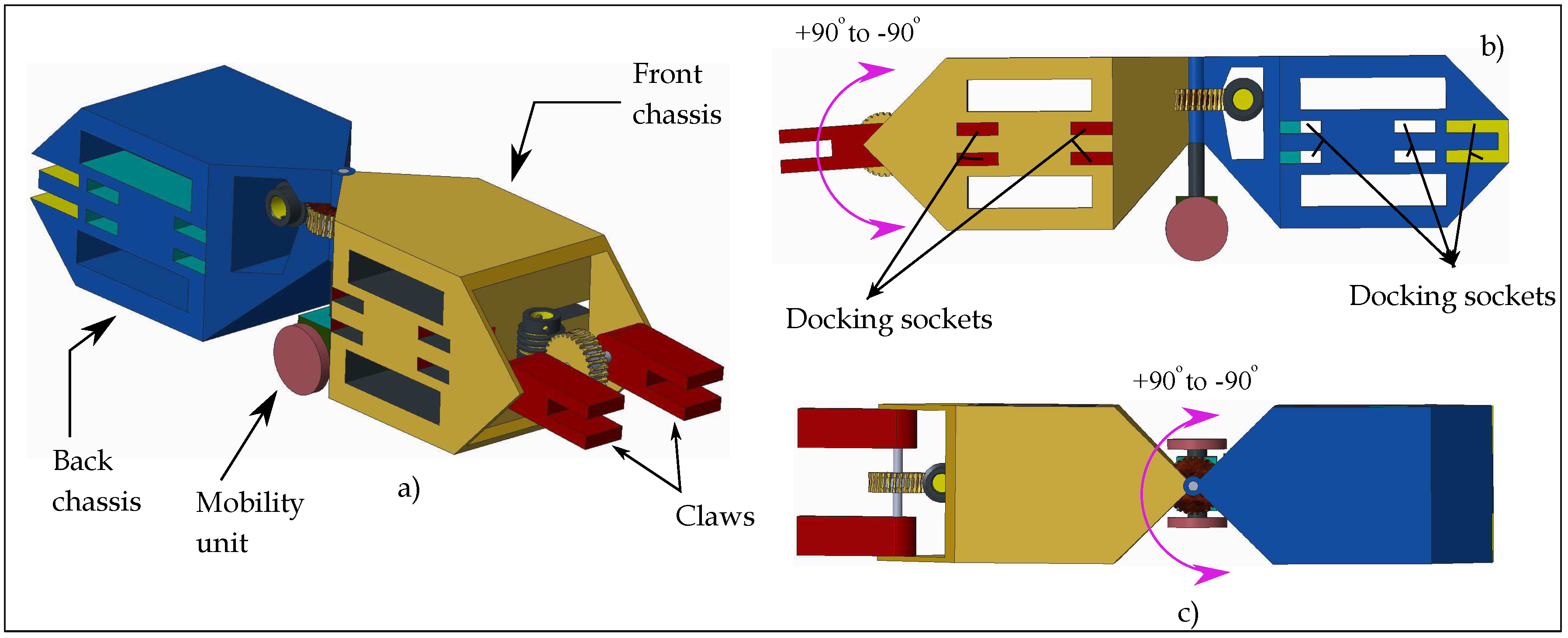
The HexaMob robotic module is designed to support the formation of chain and biomimetic structures in 2D and 3D. The hybrid category design of HexaMob along with its mobility support makes it a viable testbed for research in modular robotics. The design of HexaMob robotic module is shown in Figure 2. HexaMob robotic module is an assembly of three separate sections—Front chassis, Back chassis, and Mobility unit. The front chassis is equipped with two claws rotated by a common shaft and rotation of the shaft is sourced by a worm-gear present in front chassis. The claws are capable of positioning robotic modules mounted on them from vertically upwards (90) to vertically downwards (−90). The Front chassis also consists of docking sockets on the side faces for forming different structures. The back chassis consists of three docking faces including a face at the back along with sockets on side faces. A second worm gear mechanism is present at the center of the assembly of front and back chassis facilitating rotation around a vertical axis via a hinge mechanism. The DC motor and worm necessary for controlling the worm-gear present at the center of assembly are mounted in back chassis.
The designs of the front/back chassis is made to resemble hexagon structure both in the top and side views so that stresses on claws can be minimized in few chain structures. The robotic modules mount on chassis of each other at extreme angles of rotation and hence reducing the stresses on claws/hinges as proposed in [48]. The hinge mechanism coupled with worm-gear system present at the center of assembly provides precise control in navigation, docking and degrees of freedom for HexaMob during formation of various structures. The orientations possible with a single HexaMob robotic module upon activation of two worm gears (W.G 1 at the front and W.G 2 at the center) are shown in Figure 3.
4. HexaMob—Docking and Structures
The major merits of the HexaMob robotic module stem from the utilization of standard components in designing the robotic modules. HexaMob provides flexible possibilities for micro-sizing/macro-sizing the design in relative to numerous modular robots due to the employment of claws and vision for docking and locomotion. The locomotion in/using HexaMob robotic module is implemented by coordinated operation of a Twin-claw male interface actuated using worm-gear, a Hinge coupled worm-gear, Mobile unit, and the Vision system. The design choices for various mechanisms along with the possibilities of power and communication sharing are detailed below.
4.1. Twin-Claw Mechanism
HexaMob robotic modules are designed to employ energy-less docking mechanisms for forming structures. Numerous male interfaces for docking proposed in [48] are tested out using 3D printed models for identification of demerits and possible faults. The single claw mechanism in Figure 4a is found to be unstable during locomotion due to wobbling and the torque generation using two servo motors operating in synchronization and sharing a common axis of rotation proved to be an unsuitable mechanism due to high power consumption issues. It has been observed that a slight mismatch in the assembly of the servo motor system (due to manufacturing defects of motors or assembly materials) can push current consumption limits of both servo motor to the maximum in spite of the absence of a load. The double claw mechanism in Figure 4b is tested in the process of rectifying the power consumption issues and it has been found that such mechanism leads to structural faults and higher form-factor. In order to address issues such as continuous power consumption, latching without active parts while providing stability, more accurate control of speed and rotation, etc. the enveloped worm gear is chosen as a actuator mechanism due to its implicit locking of back-driving and torque improvement capabilities. The DC motor mounted in front chassis controls the position of claws using rotary encoders capable of measuring angles to the precision of 0.6.
The docking between various HexaMob robotic modules is facilitated by claws (male) and five female faces (each equipped with 4 sockets) as shown in Figure 2. The latching between male and female parts is firmly maintained by teeth present on the internal faces of the claws and on internal faces of the sockets as shown in Figure 5. The docking process is initiated by aligning the front faces of claw parallel to female faces of the neighboring module in front of sockets. Due to implicit gaps provided in design for sliding, the claws slide into the sockets of a neighboring module with zero force. After sliding, adjusting the angle of orientation of the claw using its worm gear leads to locking of internal teeth present in claw and female faces.
The teeth together with thin films of Velcros (not shown in Figure 5) placed on the claw and sockets can provide a firm binding during docking and locomotion for lighter loads. Since the twin claw mechanism is sourced using an enveloping worm gear as shown in Figure 4c and docking can be implemented without using energy, the HexaMob robotic module with its back-driving restriction capabilities from worm-gear maintains the structures with zero energy consumption.
4.2. Hinge Coupled Worm Gear
The first degree of freedom in HexaMob design is facilitated by twin claw mechanism located at the front of the robotic modules. The second degree of freedom is enabled by the barrel hinge mechanism located at the center of HexaMob. The hinge mechanism is rotated by a worm gear whose driving motor is mounted in the back chassis. Since direct interfacing of a DC motor to the worm extends it to outwards (refer to Figure 2b,c) of back chassis and obstructs the rotation, a bevel gear train is coupled with the worm gear for accommodating the motor in the back chassis. The gear train connecting the worm gear and bevel gears is shown in Figure 6.
The gear in the worm-gear mechanism is an integral part of the front chassis design and worm controlling the rotation of gear along with bevel gears are placed inside the back chassis of HexaMob. The mobility unit increases the inertia on the back chassis of HexaMob since it is fixed to it and hence the front chassis will rotate relative to the back chassis upon activation of bevel and worm gears providing better control in navigation/docking. The back-driving restriction mechanism was tested successfully and hence continuous power consumption can be reduced to zero while maintaining the structures along with improved control over angular velocity of rotation.
4.3. HexaMob—Mobility
Mobility is a critical feature in limiting the human intervention or maximizing the automation in robotics. Numerous wheeled steering mechanisms are considered while designing the HexaMob robotic module. The steering mechanisms such as Skid steering, Tricycle drive, Synchronous drive, Omnidirectional drive and Articulated drive are found to be conflicting with form factor constraint of the homogeneous modular design. Miniaturized robotic models of HexaMob can have two actuators in the mobility unit due to small form factor requirement for non-obstructive rotation at the center. An option of distributing the mobility actuators to front chassis and back chassis is also not viable as it adds unnecessary complexity to the steering kinematics. Differential wheel drive mechanism is chosen for the implementation due to its advantages such as easy reverse steering, and simple turning mechanism during navigation. Since the axis of rotation of worm gear mechanism at the center and axis of rotation of the mobility unit (axis when two wheels rotate in opposite direction with equal velocity) are coincident, the steering kinematics and docking process are further simplified. The Mobility unit is fixed to the back chassis adding extra inertia, and castor wheels are placed at suitable locations for providing stability to the HexaMob module. When redesigning HexaMob for heavier loads and large form factor, the motors can also be placed in back chassis such that the motor shafts can be extended into the mobility unit’s chassis in parallel from which the wheels can be connected to rotational shafts using bevel gears.
4.4. Vision System
The Vision system is a guidance mechanism for docking and navigation of HexaMob robotic modules. Unlike conventional modular designs, HexaMob design aims to inculcate a lightweight embedded electronic platform capable of assisting in docking and navigation using vision sensor into the mechanical structure similar to the trimobot robotic module. The concept of docking when the robotic modules are in proximity to each other was explored rigorously by the employment of IR sensors [18,39,49] and magnets [50,51] in the domain of modular robotics and success of such docking process is also limited to few orientations of robotic modules with respect to each other. Vision sensors aids in overcoming major limitations in autonomous docking during reconfiguration in both 2D and 3D scenarios and also automating the aggregation and dispersion processes. The major requirements of the modular robotics electronic platforms such as low power consumption, various power modes and reactiveness along with image processing capabilities are fulfilled by FlexEye platform proposed in [52] and the same platform is utilized (without transceiver) for identifying the error in alignment process during docking. The vision sensor recognizes an area of interest and calculates the alignment error between male and female interfaces with respect to its camera axis as shown in Figure 7.
Algorithm 1 implemented for recognition of error in alignment during docking process is a lightweight algorithm that recognizes a particular area of interest from a given image after converting it from a grayscale image to a binary image. The binary image is further analyzed to recognize the presence of an area of interest (a rectangle with dark borders and relatively bright internal area). The center of the rectangle and its location with respect to camera axis provides the error in alignment. A solid of pyramid structure with 1 cm side and 1 cm height, colored black on alternate faces is glued with its base parallel to the vertical plane to a rectangular structure with dark borders as shown in Figure 8 for testing the algorithm. The location of the apex of a pyramid in the image and area of bright and dark triangles provide information regarding the error in alignment with respect to the center of a image during docking when the male interface approach from various angles. The major advantage of using pyramid structure is its structural symmetry that also aids in docking when the robotic modules are floating in the air during reconfiguration. The algorithm searches for the rectangles in images and after successful recognition of rectangle(s), it searches for triangles and calculates their areas. The recognition starts with the identification of the rectangular frame to which pyramid is attached. After successful identification of frame from possible locations on the HexaMob, the pyramid projection is searched and analyzed for orientation and precise error. The identification of rectangular frame is possible in almost all cases except at the extreme conditions where the camera plane and the pyramid plane are orthogonal to each other or near to the orthogonal angles. The precise angle at which the recognition fails at extreme angles is capped only by the quality of the image sensor and the resolution of a image acquired for processing. Since the angle between the pyramid plane and camera plane while approaching for docking cannot be 90 or even close to angles such as 80, the recognition is almost always successful.
| Algorithm 1 Alignment |
|
The method of calculating the area of triangles in different scenarios shown in Figure 8 provides better results as the robotic modules move closer to each other and hence assisting in precise docking. The recognition was successfully tested in from the distance of 65 cm to 5 cm from the vision sensor. The rotation of front claws and center hinge controlled by worm gears provides precise control in both horizontal and vertical planes and hence the HexaMob docking process on five female sides can be completed in both 2D and 3D scenarios with the help of five pyramids each mounted towards the sides as shown in Figure 7.
4.5. Power and Communication Sharing
The majority of lattice structured and few chain structures modular robotic designs prototyped so far implemented power and communication channel sharing by designing docking interfaces embedded with metallic contacts connecting the batteries on multiple robotic modules using a common two-wire bus. Similarly, another two-wire bus was also made available at the same interface for sharing a communication bus for enabling locomotion and reconfiguration. The HexaMob robotic module establishes two contacts at each claw and hence there are four contacts in total with each neighboring robot after docking. The power and communication bus sharing can be implemented (if necessary) in HexaMob robotic units by placing thin uninsulated copper lines from batteries and microcontroller communication peripherals stretched over the length of internal faces of claws as shown in Figure 9 due to 100% certainty present in establishing contact at claws.
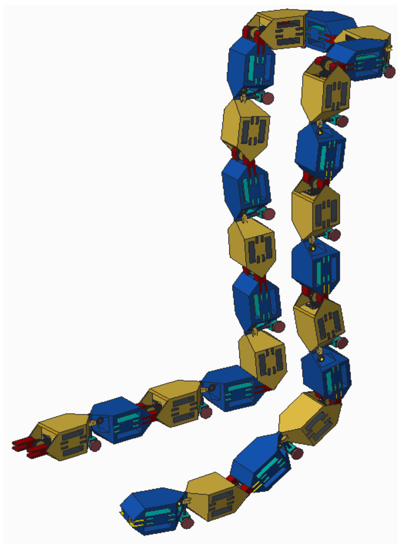
Numerous features embedded into the design of HexaMob robotic module aids in formation of multiple structures autonomously. The HexaMob design also made it possible to mimic biological organisms such as centipede and vertebrates with relative ease in docking and locomotion. Few coordinated structures that are possible with HexaMob modular robot are shown in Figure 10.
5. Path to Implementation
The HexaMob robotic unit is designed with enough spacing for integrating the electronic and other accessories necessary into the system for production of a complete robotic module. The top and bottom faces of the HexaMob can be replaced with PCB boards with necessary electronics for facilitation communication and navigation capabilities. The space between sockets and the top/bottom faces can be utilized for mounting Li-Po batteries, other sensors during macro-sizing etc.
Major design time of HexaMob is expended on analysis and modeling the worm gears as per the application requirements. Since worm gears suffer from friction present between materials participating in sliding motion, the choice of materials plays a vital role in efficiency and performance of the mechanism and hence the performance of HexaMob robotic module. The conditions for backward rotation restrictions and design parameters for worm gears are available in [53]. The Kinetic friction of various materials at numerous sliding angles are available in [54] and American Gear Manufactures Standard Association also made available optimal tables for numerous lead angles and normal pressure angles. It is possible to determine the efficiency and output torques for a given worm-gear specifications and a suitable material as per the design requirements. The HexaMob robotic module apart from worm-gear mechanism(s) uses standard components for implementing the structures and hence provides relative ease in prototyping and research. Though the losses in sliding motion are relatively large in relation to other gear mechanisms, the advantage of retaining the structure in a fail-safe state or in a recent stable state without utilizing power supersedes losses and such conservation of power by the employment of back-driving restriction mechanism continues energy conservation till the lifetime of charge in power source.
6. Results and Conclusions
A comparison of a number of modular robotic designs equipped with the self-mobility feature is listed in Table 2 and Table 3. The unsymmetrical design of M3 robotic module poses some constraints in forming structures in spite of having a precise docking mechanism and better navigation system. iMobot robotic provides better mobility and numerous possibilities for the formation of structures but exhibits less autonomous nature due to the absence of docking and undocking mechanisms. SMORES is a sophisticated modular design like iMobot equipped with docking and undocking capabilities and lack autonomous features due to lack of sensors for navigation and docking. Trimobot is unique in the perspective of enhancement of navigation and docking capabilities including omnidirectional mobility but has limitations in different structures possible with the robotic module.
The HexaMob robotic design is unique in terms of its back-driving restriction capabilities with zero energy consumption. The design of HexaMob is made with the perspective of minimizing the stresses on various internal components during configuration and locomotion while meeting all constraints of modular robots. Numerous interfaces on HexaMob increase the capabilities of the design in forming various structures and the back-driving restriction feature in locomotion improves the longevity of system by reducing the power consumption while improving torques so that implementation of gait structure for humanoid structures shown in Figure 11 is also feasible.
The HexaMob robotic design can be easily micro-scaled and macro-scaled due to its design simplicity and modularity in relative to various modular robot prototypes developed so far. Due to the independence of docking mechanism using vision sensors with other internal elements of design, the vision based alignment error detection mechanism for docking can be re-utilized without major modifications in the scaled designs. The HexaMob platform with its numerous features such as back-driving restriction, vision based docking and numerous docking interfaces and capabilities can be utilized as a testbed in the field of robotics for analysis on the performance of crawling, rolling and wheeled robots and their applications.
Author Contributions
S. Sankhar Reddy C.H. and Anupama K.R conceived and designed the models; Sharath Patlolla developed the prototypes and performed the experiments; The paper was written by Anita Agrawal and S. Sankhar Reddy C.H.
Conflicts of Interest
The authors declare no conflict of interest.
References
- Yim, M.; Shen, W.M.; Salemi, B.; Rus, D.; Moll, M.; Lipson, H.; Klavins, E. Modular Self-reconfigurable Robot Systems: Challenges and Opportunities for the Future. IEEE Robot. Autom. Mag. 2007, 14, 43–52. [Google Scholar] [CrossRef]
- Baca, J.; Pagala, P.; Rossi, C.; Ferre, M. Modular robot systems towards the execution of cooperative tasks in large facilities. Robot. Auton. Syst. 2015, 66, 159–174. [Google Scholar] [CrossRef]
- Chennareddy, S.S.R.; Agrawal, A.; Karuppiah, A. Modular Self-Reconfigurable Robotic Systems: A Survey on Hardware Architectures. J. Robot. 2017, 2017, 1–19. [Google Scholar]
- Moubarak, P.; Ben-Tzvi, P. Modular and reconfigurable mobile robotics. Robot. Auton. Syst. 2012, 60, 1648–1663. [Google Scholar] [CrossRef]
- Ahmadzadeh, H.; Masehian, E.; Asadpour, M. Modular Robotic Systems: Characteristics and Applications. J. Intell. Robot. Syst. 2016, 81, 317–357. [Google Scholar] [CrossRef]
- Fukuda, T.; Nakagawa, S. Dynamically reconfigurable robotic system. In Proceedings of the 1998 IEEE International Conference on Robotics and Automation, Philadelphia, PA, USA, 24–29 April 1988; pp. 1581–1586. [Google Scholar]
- Endo, G.; Togawa, K.; Hirose, S. Study on self-contained and terrain adaptive active cord mechanism. J. Robot. Soc. Jpn. 2000, 18, 419–425. [Google Scholar] [CrossRef]
- Togawa, K.; Mori, M.; Hirose, S. Study on three-dimensional active cord mechanism: Development of ACM-R2. In Proceedings of the 2000 IEEE/RSJ International Conference on Intelligent Robots and Systems, (IROS 2000) (Cat. No. 00CH37113), Takamatsu, Japan, 31 October–5 November 2000; Volume 3, pp. 2242–2247. [Google Scholar]
- Mori, M.; Hirose, S. Development of active cord mechanism ACM-R3 with agile 3D mobility. In Proceedings of the 2001 IEEE/RSJ International Conference on Intelligent Robots and Systems, Maui, HI, USA, 29 October–3 November 2001; Volume 3, pp. 1552–1557. [Google Scholar]
- Brown, H.B.; Vande Weghe, J.M.; Bererton, C.A.; Khosla, P.K. Millibot trains for enhanced mobility. IEEE/ASME Trans. Mechatron. 2002, 7, 452–461. [Google Scholar] [CrossRef]
- Kawakami, A.; Torii, A.; Motomura, K.; Hirose, S. SMC Rover: Planetary Rover with Transformable Wheels. In Proceedings of the 41st SICE Annual Conference on SICE 2002, Osaka, Japan, 5–7 August 2002; Volume 5, pp. 498–506. [Google Scholar]
- Wei, H.; Chen, Y.; Tan, J.; Wang, T. Sambot: A self-assembly modular robot system. IEEE/ASME Trans. Mechatron. 2011, 16, 745–757. [Google Scholar] [CrossRef]
- Harada, K.; Russo, S.; Ranzani, T.; Menciassi, A.; Dario, P. Design of Scout Robot as a robotic module for symbiotic multi-robot organisms. In Proceedings of the 2011 International Symposium on Micro-NanoMechatronics and Human Science (MHS), Nagoya, Japan, 6–9 November 2011. [Google Scholar]
- Russo, S.; Harada, K.; Ranzani, T.; Manfredi, L.; Stefanini, C.; Menciassi, A.; Dario, P. Design of a robotic module for autonomous exploration and multimode locomotion. IEEE/ASME Trans. Mechatron. 2013, 18, 1757–1766. [Google Scholar] [CrossRef]
- Zhang, Y.; Song, G.; Liu, S.; Qiao, G.; Zhang, J.; Sun, H. A Modular Self-Reconfigurable Robot with Enhanced Locomotion Performances: Design, Modeling, Simulations, and Experiments. J. Intell. Robot. Syst. Theory Appl. 2016, 81, 377–393. [Google Scholar] [CrossRef]
- Yim, M. New locomotion gaits. In Proceedings of the 1994 IEEE International Conference on Robotics and Automation, San Diego, CA, USA, 8–13 May 1994; pp. 2508–2514. [Google Scholar]
- Rubenstein, M.; Payne, K.; Will, P.; Shen, W.-M. Docking among independent and autonomous CONRO self-reconfigurable robots. In Proceedings of the 2004 IEEE International Conference on Robotics and Automation, New Orleans, LA, USA, 26 April–1 May 2004; Volume 3, pp. 2877–2882. [Google Scholar]
- Yim, M.; Zhang, Y.; Roufas, K.; Duff, D.; Eldershaw, C. Connecting and disconnecting for chain self-reconfiguration with polybot. IEEE/ASME Trans. Mechatron. 2002, 7, 442–451. [Google Scholar] [CrossRef]
- Qiao, G.; Song, G.; Zhang, J.; Sun, H.; Wang, W.; Song, A. Design of transmote: A modular self-reconfigurable robot with versatile transformation capabilities. In Proceedings of the 2012 IEEE International Conference on Robotics and Biomimetics (ROBIO), Guangzhou, China, 11–14 December 2012; IEEE: Piscataway, NJ, USA; pp. 1331–1336. [Google Scholar]
- Dasgupta, P.; Baca, J.; Hossain, S.; Dutta, A.; Nelson, C.A. Mechanical design and computational aspects for locomotion and reconfiguration of the ModRED modular robot. In Proceedings of the 2013 International Conference on Autonomous Agents and Multi-Agent Systems, St. Paul, MN, USA, 6–10 May 2013; pp. 1359–1360. [Google Scholar]
- Hossain, S.G.M.; Nelson, C.A.; Dasgupta, P. Hardware Design and Testing of ModRED: A Modular Self-Reconfigurable Robot System. In Advances in Reconfigurable Mechanisms and Robots I; Dai, J.S., Zoppi, M., Kong, X., Eds.; Springer: London, UK, 2012; pp. 515–523. [Google Scholar]
- Yim, M.; Shirmohammadi, B.; Sastra, J.; Park, M.; Dugan, M.; Taylor, C.J. Towards robotic self-reassembly after explosion. In Proceedings of the IEEE/RSJ International Conference on Intelligent Robots and Systems, San Diego, CA, USA, 29 October–2 November 2007; pp. 2767–2772. [Google Scholar]
- Jorgensen, M.W.; Ostergaard, E.H.; Lund, H.H. Modular ATRON: Modules for a self-reconfigurable robot. In Proceedings of the 2004 IEEE/RSJ International Conference on Intelligent Robots and Systems (IROS) (IEEE Cat. No. 04CH37566), Sendai, Japan, 28 September–2 October 2004; Volume 2, pp. 2068–2073. [Google Scholar]
- Schultz, U.P.; Bordignon, M.; Stoy, K. Robust and reversible self-reconfiguration. In Proceedings of the IEEE/RSJ International Conference on Intelligent Robots and Systems, IROS 2009, St. Louis, MO, USA, 10–15 October 2009; pp. 5287–5294. [Google Scholar]
- Kutzer, M.D.M.; Moses, M.S.; Brown, C.Y.; Scheidt, D.H.; Chirikjian, G.S.; Armand, M. Design of a new independently-mobile reconfigurable modular robot. In Proceedings of the 2010 IEEE International Conference on Robotics and Automation, Anchorage, AK, USA, 3–7 May 2010; pp. 2758–2764. [Google Scholar]
- Wolfe, K.C.; Moses, M.S.; Kutzer, M.D.M.; Chirikjian, G.S. M 3Express: A low-cost independently-mobile reconfigurable modular robot. In Proceedings of the 2012 IEEE International Conference on Robotics and Automation, Saint Paul, MN, USA, 14–18 May 2012; pp. 2704–2710. [Google Scholar]
- Ko, D.; Cheng, H.H. Programming reconfigurable modular robots. In Proceedings of the 2012 IEEE/ASME 8th IEEE/ASME International Conference on Mechatronic and Embedded Systems and Applications, Suzhou, China, 8–10 July 2012; IEEE: Piscataway, NJ, USA, 2012; pp. 160–165. [Google Scholar]
- Davey, J.; Kwok, N.; Yim, M. Emulating self-reconfigurable robots—Design of the SMORES system. In Proceedings of the 2012 IEEE International Conference on Intelligent Robots and Systems, Vilamoura, Portugal, 7–12 October 2012; pp. 4464–4469. [Google Scholar]
- Murata, S.; Yoshida, E.; Kamimura, A.; Kurokawa, H.; Tomita, K.; Kokaji, S. M-TRAN: Self-reconfigurable modular robotic system. IEEE/ASME Trans. Mechatron. 2002, 7, 431–441. [Google Scholar] [CrossRef]
- Kurokawa, H.; Kamimura, A.; Yoshida, E.; Tomita, K.; Kokaji, S.; Murata, S. M-TRAN II: Metamorphosis from a four-legged walker to a caterpillar. In Proceedings of the 2003 IEEE/RSJ International Conference on Intelligent Robots and Systems (IROS), Las Vegas, NV, USA, 27–31 October 2003; Volume 3, pp. 2454–2459. [Google Scholar]
- Kurokawa, H.; Tomita, K.; Kamimura, A.; Kokaji, S.; Hasuo, T.; Murata, S. Distributed Self-Reconfiguration of M-TRAN III Modular Robotic System. Int. J. Robot. Res. 2008, 27, 373–386. [Google Scholar] [CrossRef]
- Zhu, Y.; Zhao, J.; Cui, X.; Wang, X.; Tang, S.; Zhang, X.; Yin, J. Design and implementation of UBot: A modular Self-Reconfigurable Robot. In Proceedings of the 2013 IEEE International Conference on Mechatronics and Automation, Takamatsu, Japan, 4–7 August 2013; IEEE: Piscataway, NJ, USA; pp. 1217–1222. [Google Scholar]
- Neubert, J.; Lipson, H. Soldercubes: A self-soldering self-reconfiguring modular robot system. Auton. Robots 2016, 40, 139–158. [Google Scholar] [CrossRef]
- Parrott, C.; Dodd, T.J.; Gross, R. HyMod: A 3-DOF Hybrid Mobile and Self-Reconfigurable Modular Robot and its Extensions. In Proceedings of the 13th International Symposium on Distributed Autonomous Robotic Systems, London, UK, 6–9 November 2016. [Google Scholar]
- Liedke, J.; Matthias, R.; Winkler, L.; Worn, H. The Collective Self-reconfigurable Modular Organism (CoSMO). In Proceedings of the 2013 IEEE/ASME International Conference on Advanced Intelligent Mechatronics, Wollongong, Australia, 9–12 July 2013; pp. 1–6. [Google Scholar]
- Hamlin, G.J.; Sanderson, A.C. TETROBOT: A modular approach to parallel robotics. IEEE Robot. Autom. Mag. 1997, 4, 42–50. [Google Scholar] [CrossRef]
- Ramchurn, V.; Richardson, R.C.; Nutter, P. ORTHO-BOT: A Modular Reconfigurable Space Robot Concept. In Proceedings of the 8th International Conference on Climbing and Walking Robots and the Support Technologies for Mobile Machines (CLAWAR 2005), London, UK, 13–15 September 2005; Tokhi, M.O., Virk, G.S., Hossain, M.A., Eds.; Springer: Berlin, Germany, 2006; pp. 659–666. [Google Scholar]
- Lyder, A.; Garcia, R.F.M.; Stoy, K. Mechanical design of Odin, an extendable heterogeneous deformable modular robot. In Proceedings of the IEEE/RSJ International Conference on Intelligent Robots and Systems, Nice, France, 22–26 September 2008; pp. 883–888. [Google Scholar]
- Campbell, J.; Pillai, P.; Goldstein, S.C. The robot is the tether: Active, adaptive power routing for modular robots with unary inter-robot connectors. In Proceedings of the 2005 IEEE/RSJ International Conference on Intelligent Robots and Systems, Edmonton, AB, Canada, 2–6 August 2005; pp. 2960–2967. [Google Scholar]
- Shimizu, M.; Mori, T.; Ishiguro, A. A development of a modular robot that enables adaptive reconfiguration. In Proceedings of the 2006 IEEE International Conference on Intelligent Robots and Systems, Beijing, China, 9–15 October 2006; pp. 174–179. [Google Scholar]
- Karagozler, M.E.; Goldstein, S.C.; Reid, J.R. Stress-driven MEMS assembly + electrostatic forces = 1 mm diameter robot. In Proceedings of the 2009 IEEE/RSJ International Conference on Intelligent Robots and Systems, St. Louis, MO, USA, 10–15 October 2009; pp. 2763–2769. [Google Scholar]
- Krivokon, M.; Everist, J.; Rubenstein, M.; Venkatesh, J. Multimode locomotion via SuperBot robots. In Proceedings of the 2006 IEEE International Conference on Robotics and Automation, Orlando, FL, USA, 15–19 May 2006; IEEE: Piscataway, NJ, USA; pp. 2552–2557. [Google Scholar]
- Shen, W.M.; Kovac, R.; Rubenstein, M. Singo: A single-end-operative and genderless connector for self-reconfiguration, self-assembly and self-healing. In Proceedings of the IEEE International Conference on Robotics and Automation, Kobe, Japan, 12–17 May 2009; pp. 4253–4258. [Google Scholar]
- Liu, W.; Winfield, A.F.T. Morphogenetic Engineering. Morphog. Eng. 2012, 9, 61–87. [Google Scholar]
- Ryland, G.G.; Cheng, H.H. Design of iMobot, an intelligent reconfigurable mobile robot with novel locomotion. In Proceedings of the 2010 IEEE International Conference on Robotics and Automation, Anchorage, AK, USA, 3–7 May 2010; pp. 60–65. [Google Scholar]
- Sfcl, I.M.T.; Chung, D.C.; Yoo, B.H.; Cho, Y.S.; Jung, B.I.; Choi, H.S.; Sung, T.H. Design and Characterization of the EP-Face Connector. In Proceedings of the 2016 IEEE/RSJ International Conference on Intelligent Robots and Systems (IROS), Daejeon, South Korea, 9–14 October 2016. [Google Scholar]
- Jing, G.; Tosun, T.; Yim, M.; Kress-Gazit, H. An End-To-End System for Accomplishing Tasks with Modular Robots. In Proceedings of the Robotics: Science and Systems, Ann Arbor, MI, USA, 18–22 June 2016. [Google Scholar]
- Sankhar, C.S.; Agrawal, A.; Anupama, K.R. SQ-BOT—A Modular Robot Prototype for Self- Reconfiguring Structures. In Proceedings of the International Conference on Robotics: Current Trends and Future Challenges (RCTFC), Thanjavur, India, 19–20 December 2016; IEEE: Piscataway, NJ, USA; pp. 1–6. [Google Scholar]
- An, B.K. EM-Cube: Cube-shaped, self-reconfigurable robots sliding on structure surfaces. In Proceedings of the IEEE International Conference on Robotics and Automation, Pasadena, CA, USA, 19–23 May 2008; pp. 3149–3155. [Google Scholar]
- Murata, S.; Kurokawa, H.; Kokaji, S. Self-assembling machine. In Proceedings of the IEEE International Conference on Robotics and Automation, San Diego, CA, USA, 8–13 May 1994; IEEE: Piscataway, NJ, USA; pp. 441–448. [Google Scholar]
- Romanishin, J.W.; Gilpin, K.; Claici, S.; Rus, D. 3D M-Blocks: Self-reconfiguring robots capable of locomotion via pivoting in three dimensions. In Proceedings of the 2015 IEEE International Conference on Robotics and Automation (ICRA), Seattle, WA, USA, 26–30 May 2015; pp. 1925–1932. [Google Scholar]
- Anupama, K.R.; Reddy, C.S.S.; Shenoy, M.V. FlexEye—A flexible camera mote for sensor networks. In Proceedings of the 2015 2nd International Conference on Signal Processing and Integrated Networks (SPIN), Noida, India, 19–20 February 2015; IEEE: Piscataway, NJ, USA; pp. 1010–1015. [Google Scholar]
- Richard Budynas, K.N. Shigley’s Mechanical Engineering Design, 10th ed.; McGraw Hill: New York, NY, USA, 2014. [Google Scholar]
- Rothbart, H.A.; Brown, T.H. Mechanical Design Handbook: Measurement, Analysis and Control of Dynamic Systems (Handbooks); McGraw Hill: New York, NY, USA, 2006. [Google Scholar]
Figure 1.
(a) M3 modular robot; (b) iMobot modular robot.
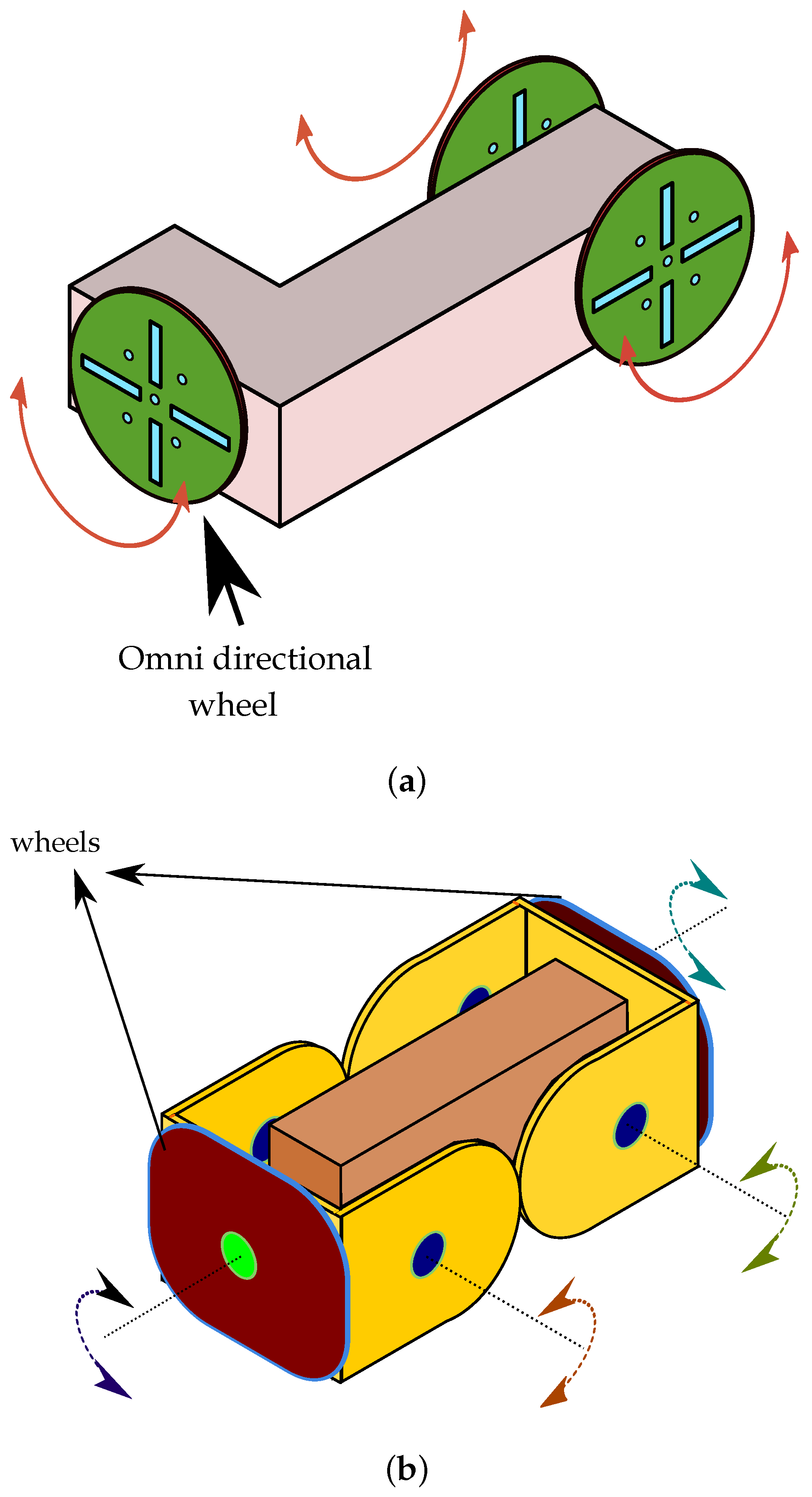
Figure 2.
HexaMob robotic module. (a) 3D view; (b) Side view; (c) Top view.

Figure 3.
HexaMob—Orientations.
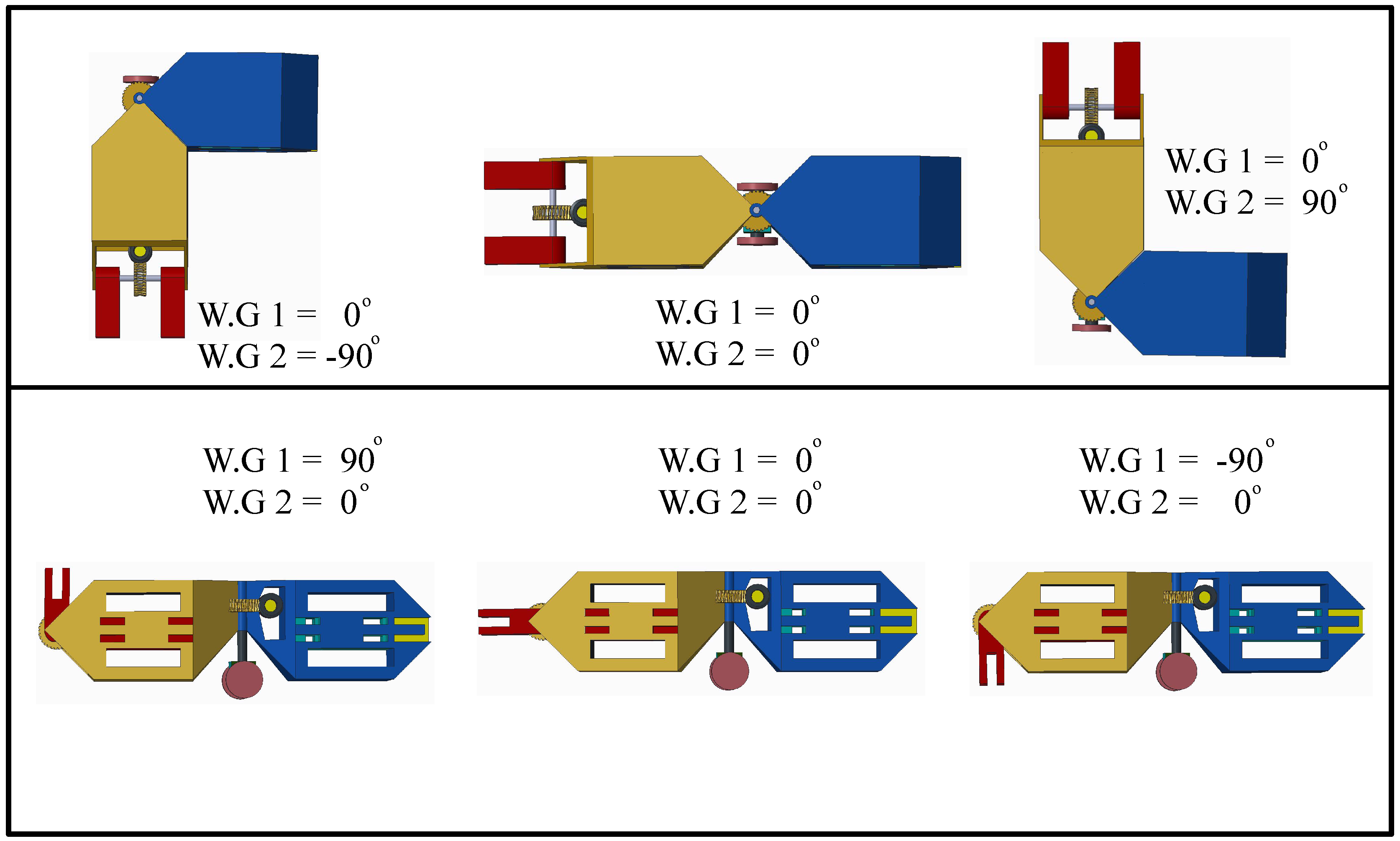
Figure 4.
Docking Prototypes. (a) Single claw—double servo; (b) Double claw—double servo; (c) Double claw—Worm gear.
Figure 4.
Docking Prototypes. (a) Single claw—double servo; (b) Double claw—double servo; (c) Double claw—Worm gear.
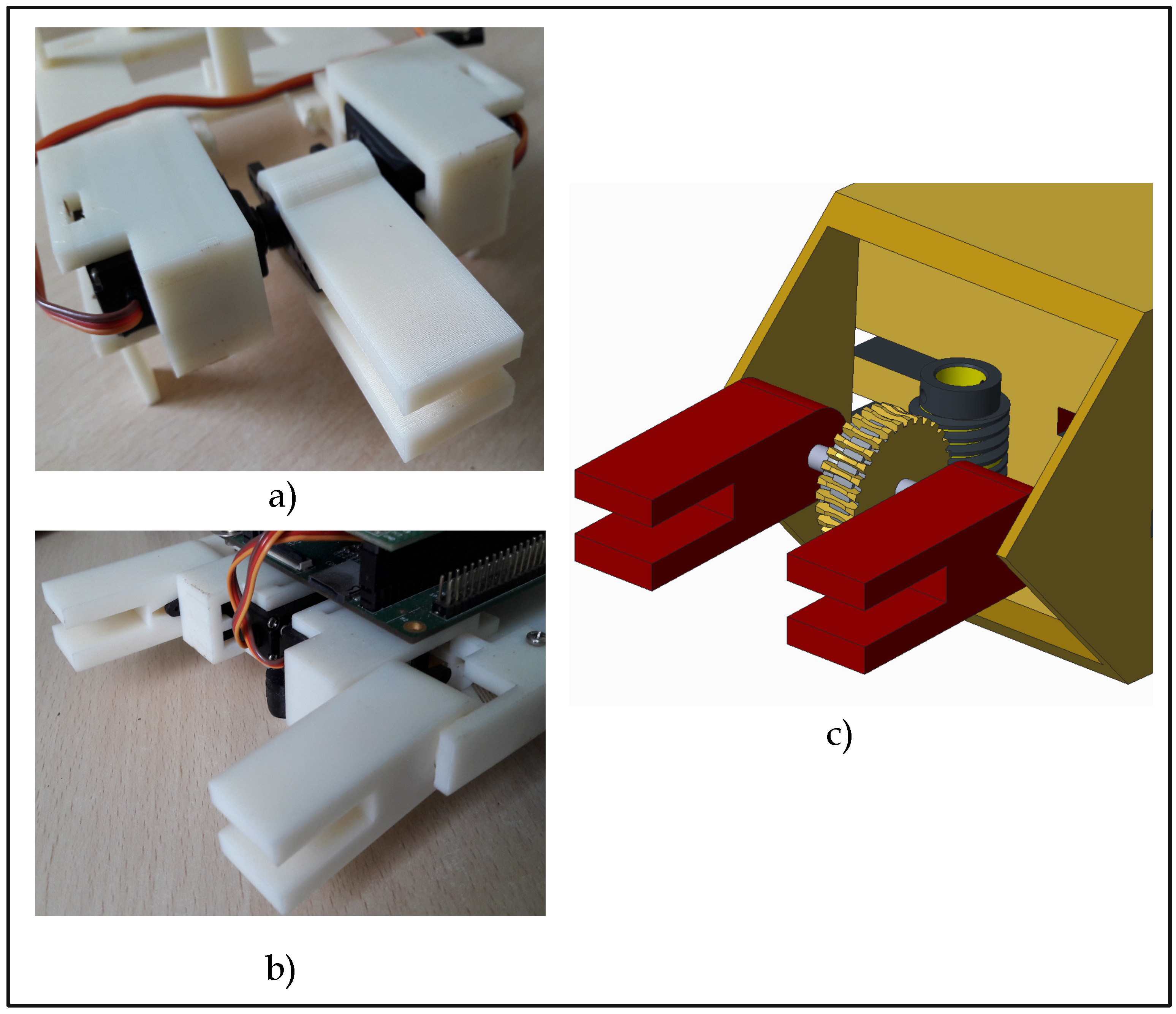
Figure 5.
HexaMob—Latching process.
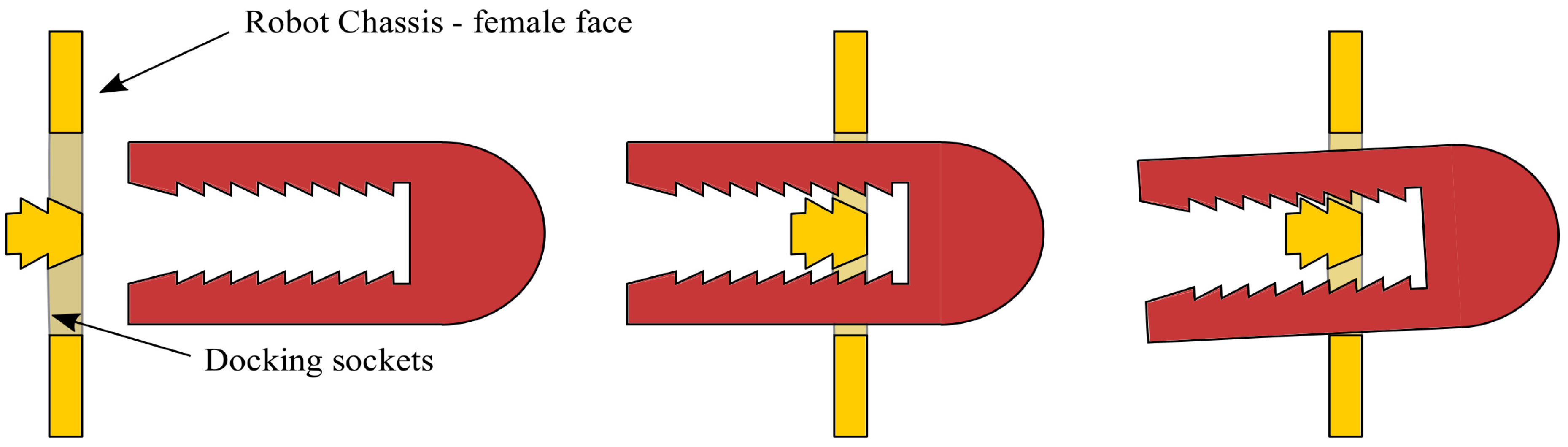
Figure 6.
Worm and Bevel gear assembly (a) Worm gear location in HexaMob robot; (b) 3D-prototype for testing.
Figure 6.
Worm and Bevel gear assembly (a) Worm gear location in HexaMob robot; (b) 3D-prototype for testing.
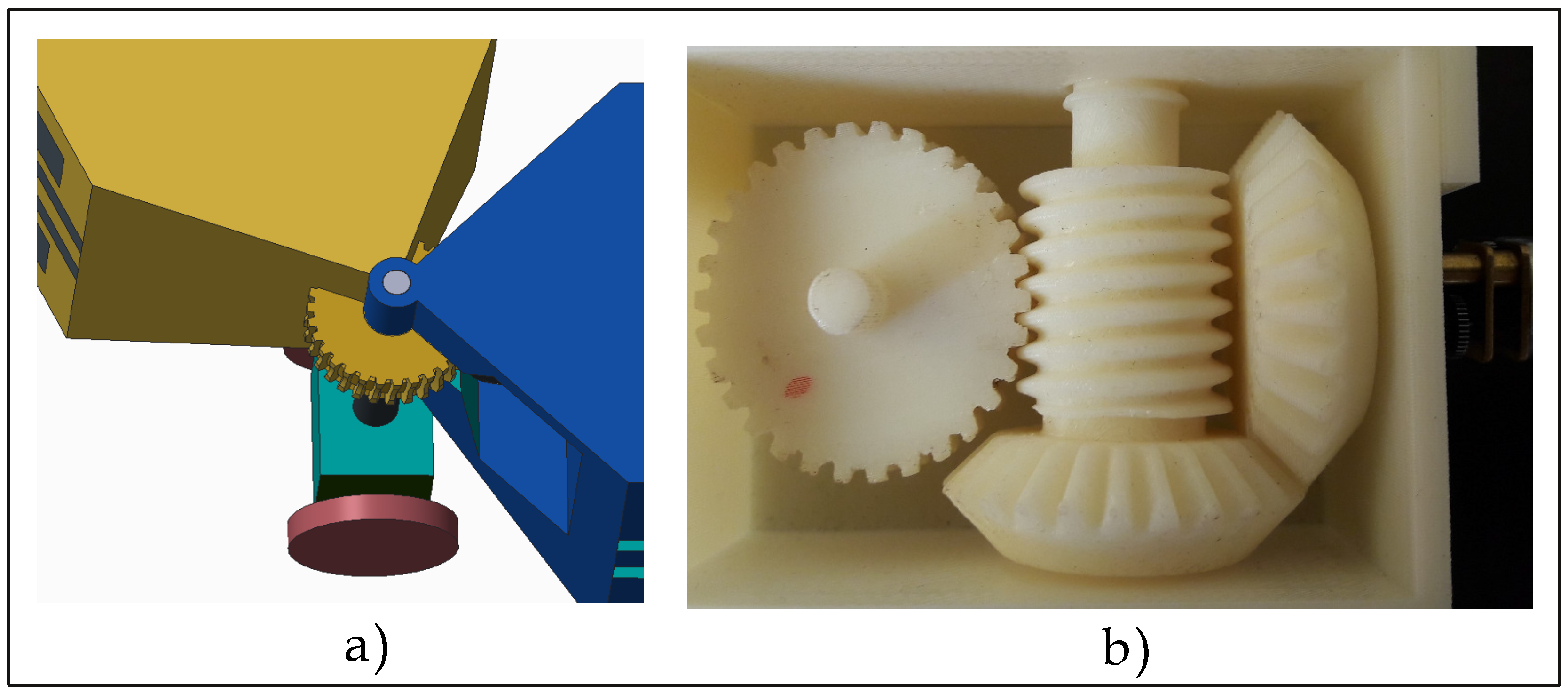
Figure 7.
HexaMob robotic module—Alignment using vision sensors.
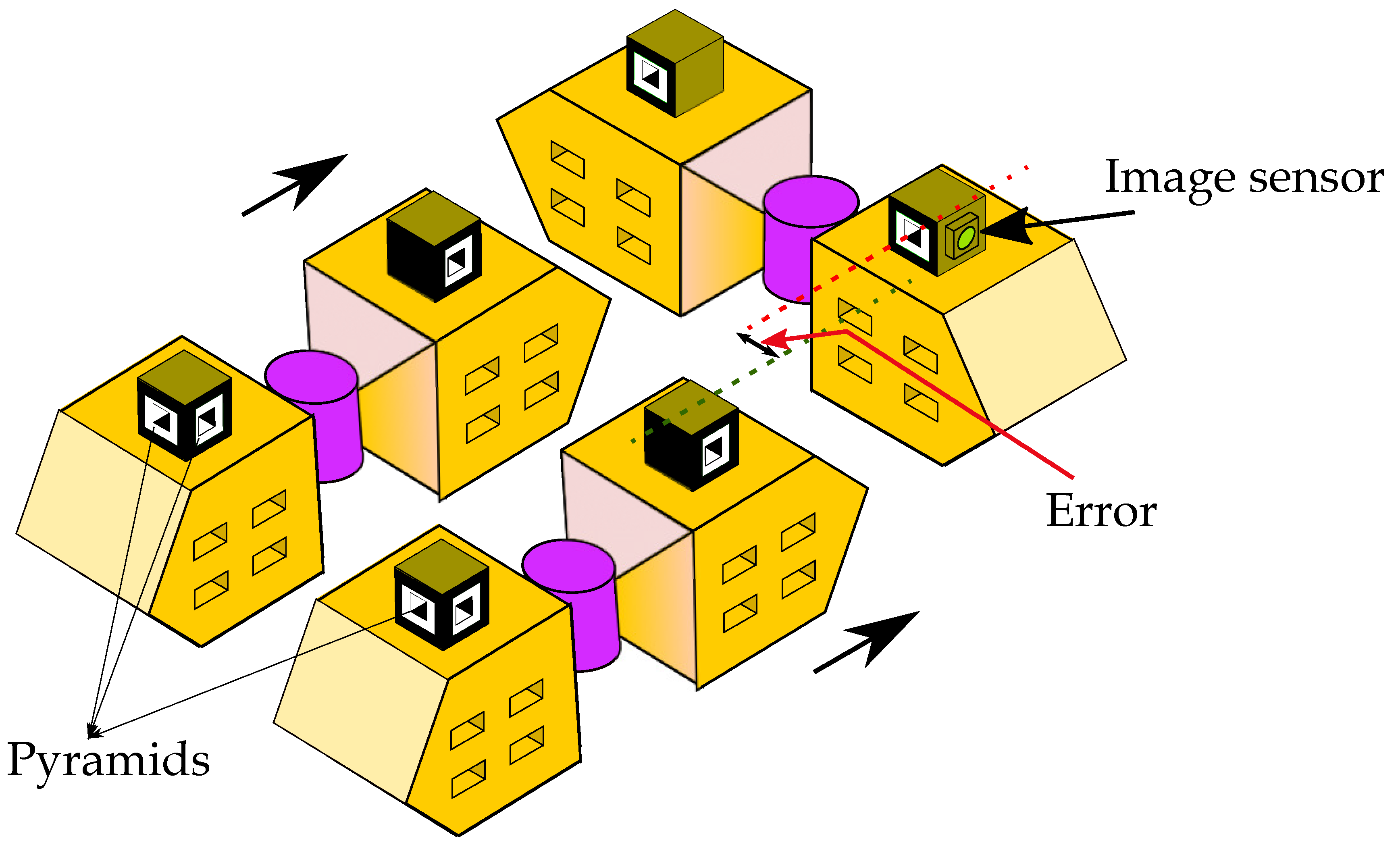
Figure 8.
(a) Acquired images (b) Binary images from image processing (c) Acquired high resolution images of pyramid for further analysis (d) High resolution binary images of pyramid from image processing (e) Scenario with target object aligned with vertical axis of vision sensor and placed at 65 cm distance from camera module (f) Scenario with target object to the right of vertical axis of vision sensor and on horizontal line normal to vertical axis drawn at a distance of 65 cm from sensor (g) Scenario with target object to the left of vertical axis of vision sensor and on horizontal line normal to vertical axis drawn at a distance of 65 cm from sensor (h) Scenario with target object at center of camera axis and on a perpendicular line drawn at 20 cm from vision sensor (i) Scenario with target object to the left of vertical axis of vision sensor and on horizontal line normal to vertical axis drawn at a distance of 20 cm from sensor.

Figure 9.
HexaMob robotic module—Contacts - a) 3D view b) Side view.
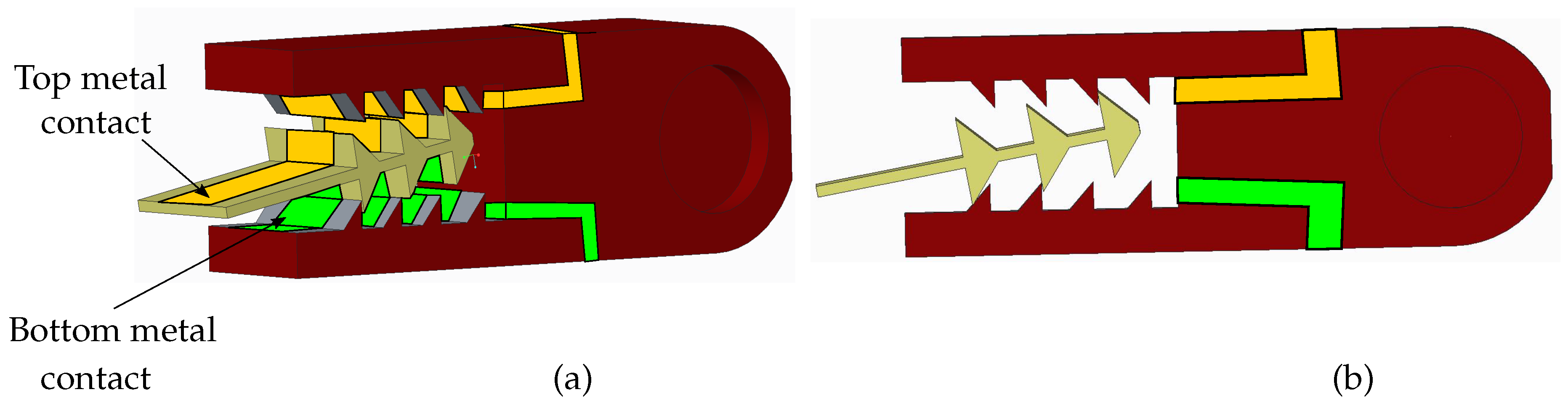
Figure 10.
Coordinated structures using HexaMob (a) Square structure (Top view); (b) hexagon structure (Top view); (c) 3D stacked Square structures; (d) chain structure—snake; (e) biomimetic structure—Vertebrates (Top view); (f) biomimetic structure—Centipede.
Figure 10.
Coordinated structures using HexaMob (a) Square structure (Top view); (b) hexagon structure (Top view); (c) 3D stacked Square structures; (d) chain structure—snake; (e) biomimetic structure—Vertebrates (Top view); (f) biomimetic structure—Centipede.
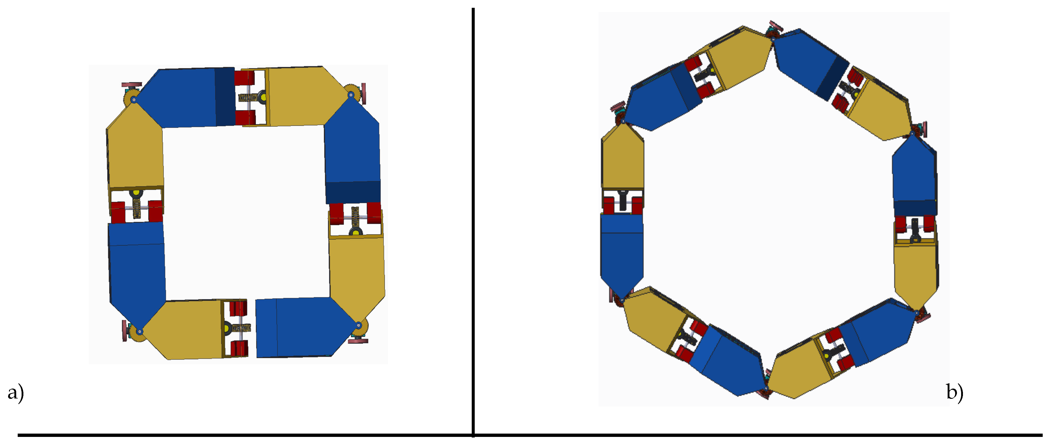
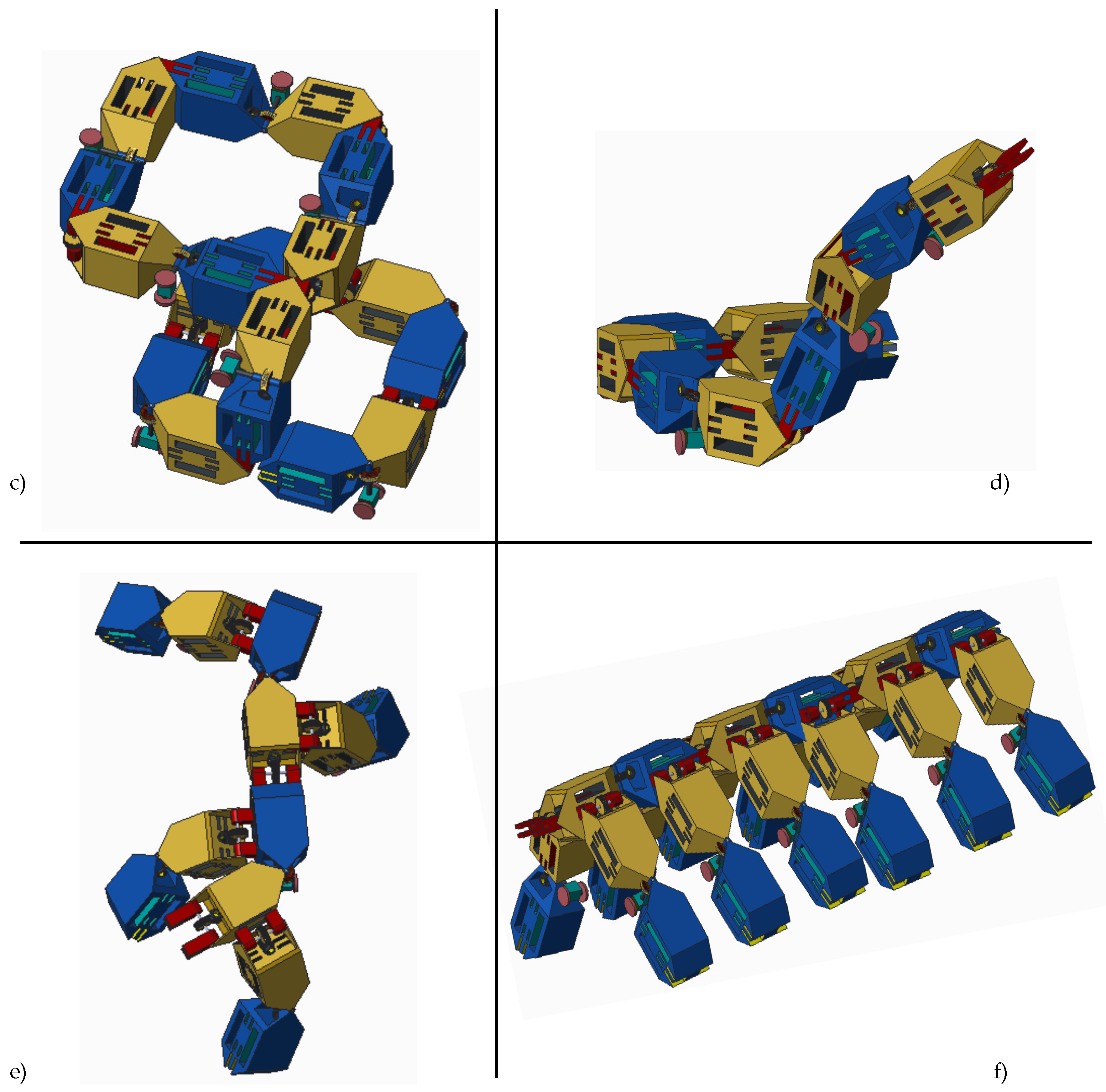
Figure 11.
HexaMob co-ordinated gait structure.

Table 1.
Classification of Modular self-reconfigurable robots.
| Structures | Locomotion | Form-Factor | Reconfiguration |
|---|---|---|---|
| Lattice | Mobile | Micro | Stochastic |
| Chain | Co-ordinated | Mini | Deterministic |
| Hybrid | External | Macro | |
| Truss | |||
| Free-form |
Table 2.
Comparison of hardware features in Hybrid modular robotic designs equipped with self-mobility.
Table 2.
Comparison of hardware features in Hybrid modular robotic designs equipped with self-mobility.
| Robot | Shape | Docking | Connection | Mobility | Reference | ||
|---|---|---|---|---|---|---|---|
| Interface | Actuator | Active | Inactive | ||||
| M3 | ’L’ shaped | Hooks | DC motor | 3 | 0 | Omni directional | [25] |
| M3express | ’L’ shaped | Latch | SMA, Servo | 3 | 0 | Omni directional | [26] |
| iMobot | Cuboid | Latch | Manual | 0 | 6 | Differential drive | [45] |
| SMORES | Cube | Magnets | DC motor | 3 | 1 | Differential drive | [28] |
| Trimobot | Hexagonal | Hooks | DC motor | 1 Male | 5 Female | Omni directional | [15] |
| CoSMO | Cube | Lock | DC motor | 4 | 0 | Omni- directional | [35] |
| Scout | Cube | Lock | DC motor | 4 | 0 | Tracks | [13,14] |
| Sambot | Cube | Hooks | DC motor | 1 Male | 5 female | Differential drive | [12] |
| HexaMob | Hexagonal | Claw | Worm gear | 1 Male | 5 Female | Differential drive | |
Table 3.
Comparison of reconfiguration features in Hybrid modular robotic designs equipped with self-mobility.
Table 3.
Comparison of reconfiguration features in Hybrid modular robotic designs equipped with self-mobility.
| Robot | Degrees of Freedom | Back-Driving Restriction Capabilities | Power Sharing Capabilities | Reconfiguration Autonomous Features | Reference |
|---|---|---|---|---|---|
| M3 | 3D | ✘ | ✘ | [25] | |
| M3express | 3D | ✘ | ✘ | [26] | |
| iMobot | 3D | ✘ | ✘ | [45] | |
| SMORES | 3D | ✘ | ✘ | [28] | |
| Trimobot | 3D | ✘ | ✘ | [15] | |
| CoSMO | 3D | ✘ | ✓ | [35] | |
| Scout | 3D | ✘ | ✓ | [13,14] | |
| Sambot | 3D | ✘ | ✓ | [12] | |
| HexaMob | 3D | ✓ | ✓ |
⊙-Biomimetic capabilities, †-Autonomous features, ‡-Chain structures, ☆-Lattic structures.
© 2017 by the authors. Licensee MDPI, Basel, Switzerland. This article is an open access article distributed under the terms and conditions of the Creative Commons Attribution (CC BY) license (http://creativecommons.org/licenses/by/4.0/).
Share and Cite
MDPI and ACS Style
CH., S.S.R.; Patlolla, S.; Agrawal, A.; K. R., A. HexaMob—A Hybrid Modular Robotic Design for Implementing Biomimetic Structures. Robotics 2017, 6, 27. https://doi.org/10.3390/robotics6040027
AMA Style
CH. SSR, Patlolla S, Agrawal A, K. R. A. HexaMob—A Hybrid Modular Robotic Design for Implementing Biomimetic Structures. Robotics. 2017; 6(4):27. https://doi.org/10.3390/robotics6040027
Chicago/Turabian StyleCH., Sasanka Sankhar Reddy, Sharath Patlolla, Anita Agrawal, and Anupama K. R. 2017. "HexaMob—A Hybrid Modular Robotic Design for Implementing Biomimetic Structures" Robotics 6, no. 4: 27. https://doi.org/10.3390/robotics6040027
Note that from the first issue of 2016, this journal uses article numbers instead of page numbers. See further details here.