Simple Reflex Controller for Decentralized Motor Coordination Based on Resonant Oscillation

Department of Mechanical Engineering, Osaka University, 2-1, Yamadaoka, Suita, Osaka 565-0871, Japan
*
Author to whom correspondence should be addressed.
†
These authors contributed equally to this work.
Robotics 2018, 7(2), 23; https://doi.org/10.3390/robotics7020023
Submission received: 7 April 2018
/
Revised: 20 May 2018
/
Accepted: 24 May 2018
/
Published: 28 May 2018
Abstract
:This article describes an extremely simple controller as a minimal example of decentralized motor coordination and gait generation. The control strategy is based on the stretch reflex in animals and requires no mutual communication or detailed body models. Despite such simplicity, each controller can sync itself and generate various resonant oscillation by only physical interaction through whole body dynamics. To evaluate this controller, we conduct some simulations with a linear spring–mass–damper system and a nonlinear legged robot model with multiple controllers. The former shows an adaptability to change in vibration frequency and the body parameter. In the latter, first we show a limitation of the proposed method due to the nonlinearity, and an alternative method is proposed. Finally, the simple controllers generate versatile gaits just by choosing a control parameter of “speeding up or down,” and the gait generation can be explained by the controllers–body integration based on resonant oscillation.
1. Introduction
Animals can adjust their motion to their environmental conditions. As typically observed in their locomotive behavior, they synchronize multiple periodic motions of the limbs and the body to each other, and make them adapt to the external force from the ground. This topic has long been discussed by biologists [1,2], including a well-known result showing that horses select a gait that is suitable for their speed [3] in terms of energy consumption. On the other hand, in the field of robotics, adaptive motor coordination in animals still requires study.
An important keyword to discuss this topic is reflex. Reflex is an involuntary motor control, which is mainly used for relatively quick and simple motion tasks, while voluntary control is slower but suitable for complicated tasks. Research shows that this reflex control contributes to various quick adaptations. In particular, a classic study using decerebrated cats [4] showed that the reflex control provides functions to adapt a muscle activity to changes in a load [5] and stabilizes a gait pattern during walking [6]. The reflex also contributes to human locomotions [7], in terms of stability during standing [8], walking [9], and hopping [10,11,12].
As an artificial scheme to generate rhythmic patterns, the idea of central pattern generators (CPGs) [13] were proposed based on a model of neural circuits in the spinal cord. CPGs generate various locomotor patterns by designing a network connection between neuron modules.
Moreover, Owaki et al. [14] proposed a simple decentralized control scheme that does not require any inter-neural communication. This controller allowed versatile gait transitions by exploiting a physical (non-neural) inter-limb interaction. This result suggests that physical interaction between the independent controllers through body dynamics is important for the generation of synchronized periodic motions.
When it comes to body physics, studies of a passive dynamic walker [15,16] demonstrated that the mechanical dynamics of the robot leg plays a large part in gait stability. A biped walker [17] and passive quadrupeds [18,19] achieved gait transitions by only the body dynamics. Moreover, some results showed the functions of partial body dynamics for legged locomotion, including swing-leg retraction [20], compliant legs [21,22], and torsos [23]. Although the functions of partial body dynamics in animals were suggested in these studies, whole body dynamics is still entangled.
An alternative approach based on free vibration was taken in order to deal with whole body dynamics explicitly. Inspired by the experiment with horses [3], a study [24] suggested that there is a correspondence between the gaits of actual horses and the free vibration modes of a horse model. In this paradigm, some authors [25,26] proposed a methodology to control the whole body motion based on free vibration. Their robots had a simple elastic body and a vibration motor that achieves an energy-efficient hopping motion by exploiting the free vibration mode of the robot body.
In this paper, we propose an extremely simple controller based on reflexes and investigate the controllers–body integration based on resonant oscillation. This paper shows that the simple controller can automatically generate versatile motion patterns, as animals do. In our approach, multiple controllers are decentralized in each part of the robot body as a control module. Each module is composed of an actuator part, which is modeled as a linear actuator with a spring–damper, and a controller part, which provides oscillation and a reflex function. If the controller module is subject to an external force from the robot body and environment, then the controller senses an internal force in the spring–damper, and it adjusts the natural length of the actuator part. This control strategy is based on the stretch reflex in animals that functions to maintain a current muscle length when the muscle senses internal force. To model this reflex function simply, the proposed controller maintains a current length of the linear actuator by delaying the oscillation speed according to the magnitude of the internal force in the actuator. This controller syncs the multiple controllers and the whole body dynamics with the resonant modes by only physical interaction. Moreover, by selecting a scalar parameter of the controllers, seamless transitions between the resonant modes are achieved. To evaluate this method, we conduct some simulations with linear and nonlinear systems, which interact with an external environment. The first simulation is with a linear spring–mass–damper system that has two reflex controllers, and the second is with a quadruped legged robot that is modeled in a sagittal plane [27]. Finally, the simple controllers generate versatile gaits just by choosing a control parameter of “speeding up or down.”
2. Reflex Controller for Resonance Mode Excitation
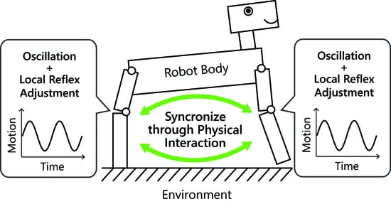
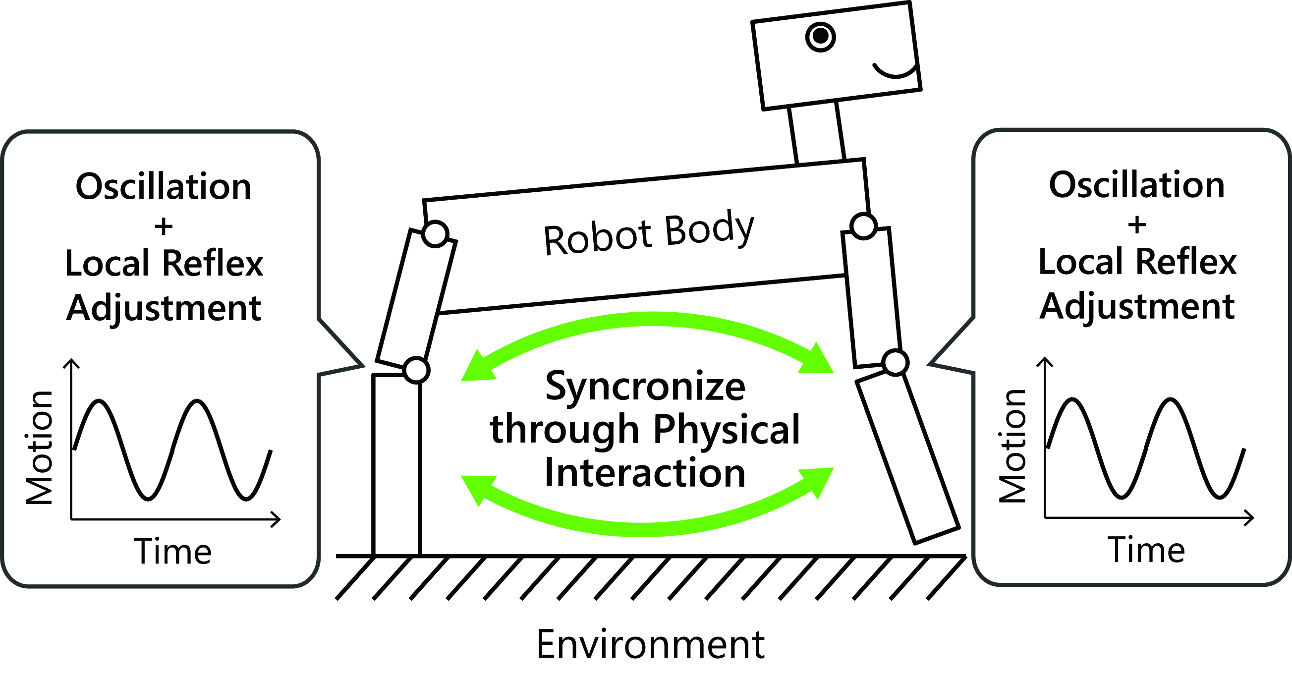
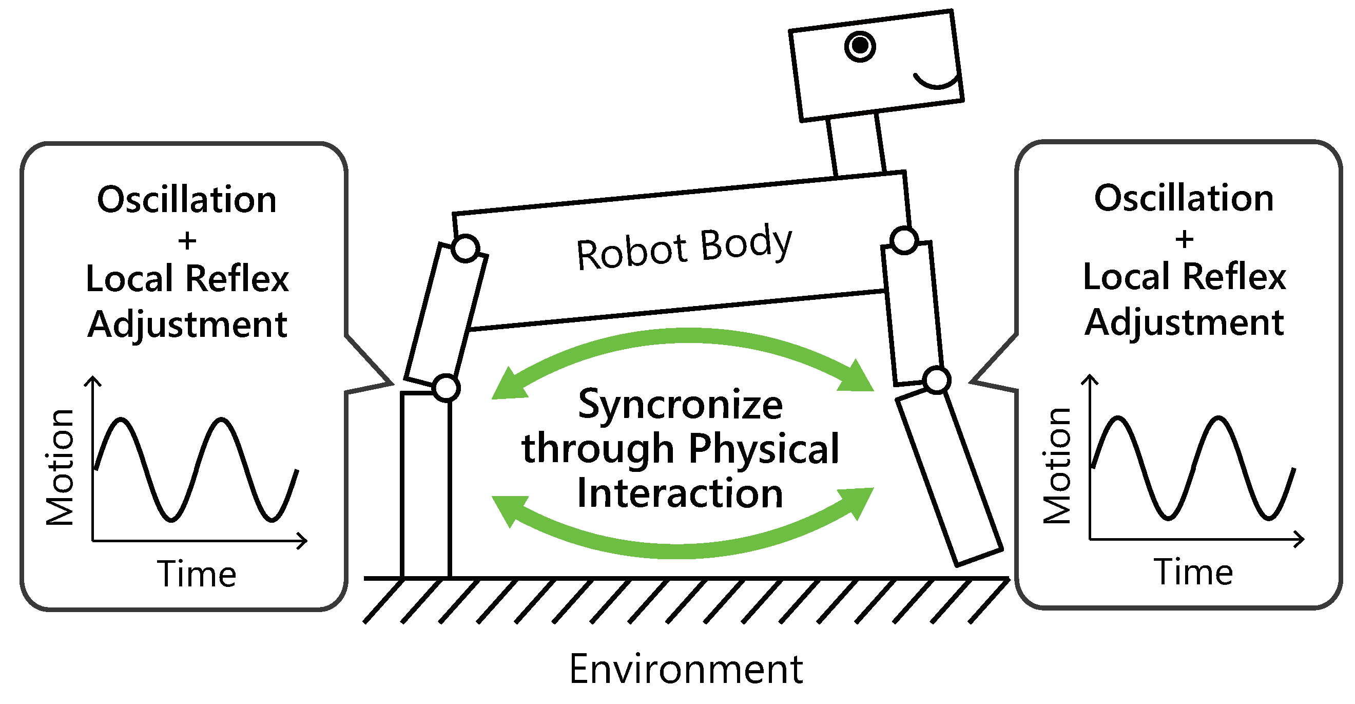
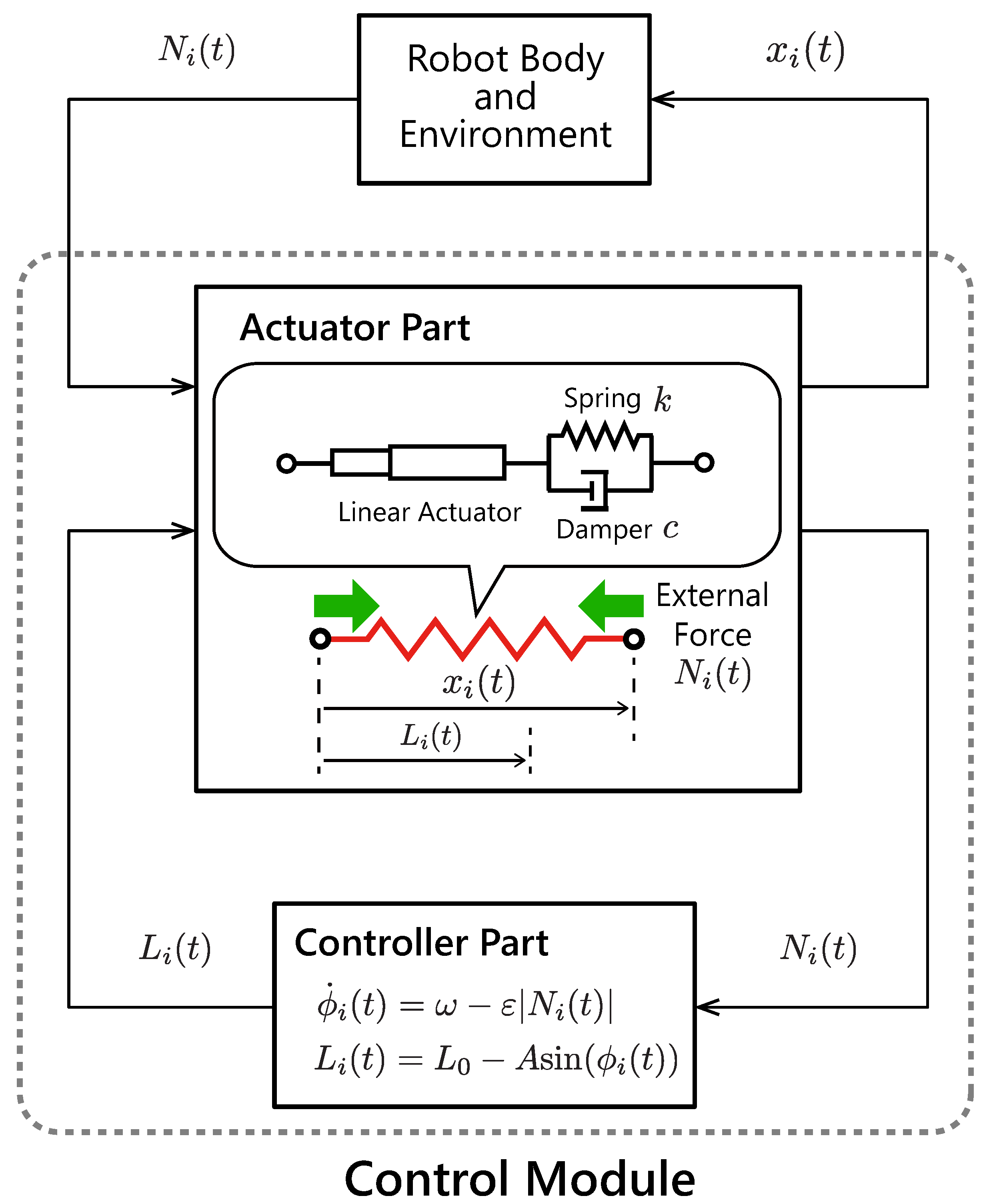
This article describes an extremely simple controller to achieve the controllers–body integration based on resonant oscillation (Figure 1). Let multiple controllers be decentralized in each part of the robot body as a control module. Figure 2 illustrates the structure of the proposed control module. Each module is composed of an actuator part, which is modeled as a linear actuator with a spring–damper, and a controller part, which provides oscillation and a reflex function. If the controller module is subjected to an external force from the robot body and environment, then the controller senses an internal force in the spring–damper and adjusts the natural length of the actuator part. This control strategy is based on the stretch reflex: a kind of involuntary control circuit in animals. When an animal muscle receives a force from the body or the external environment, the stretch reflex functions to maintain a current muscle length. To model this reflex function simply, the proposed controller maintains a current length of the linear actuator by delaying the oscillation speed according to the magnitude of the internal force in the actuator.
The proposed control strategy in the i-th module is written as
where is the phase of the ith controller, is the intrinsic angular velocity, and is sensory gain. is the internal force in the corresponding linear actuator.
Each linear actuator i is modeled as a spring–damper, so the internal force in the actuator and the actuator length obey the following equation:
where and denote the viscoelastic constants. Each controller i drives the natural length of the actuator
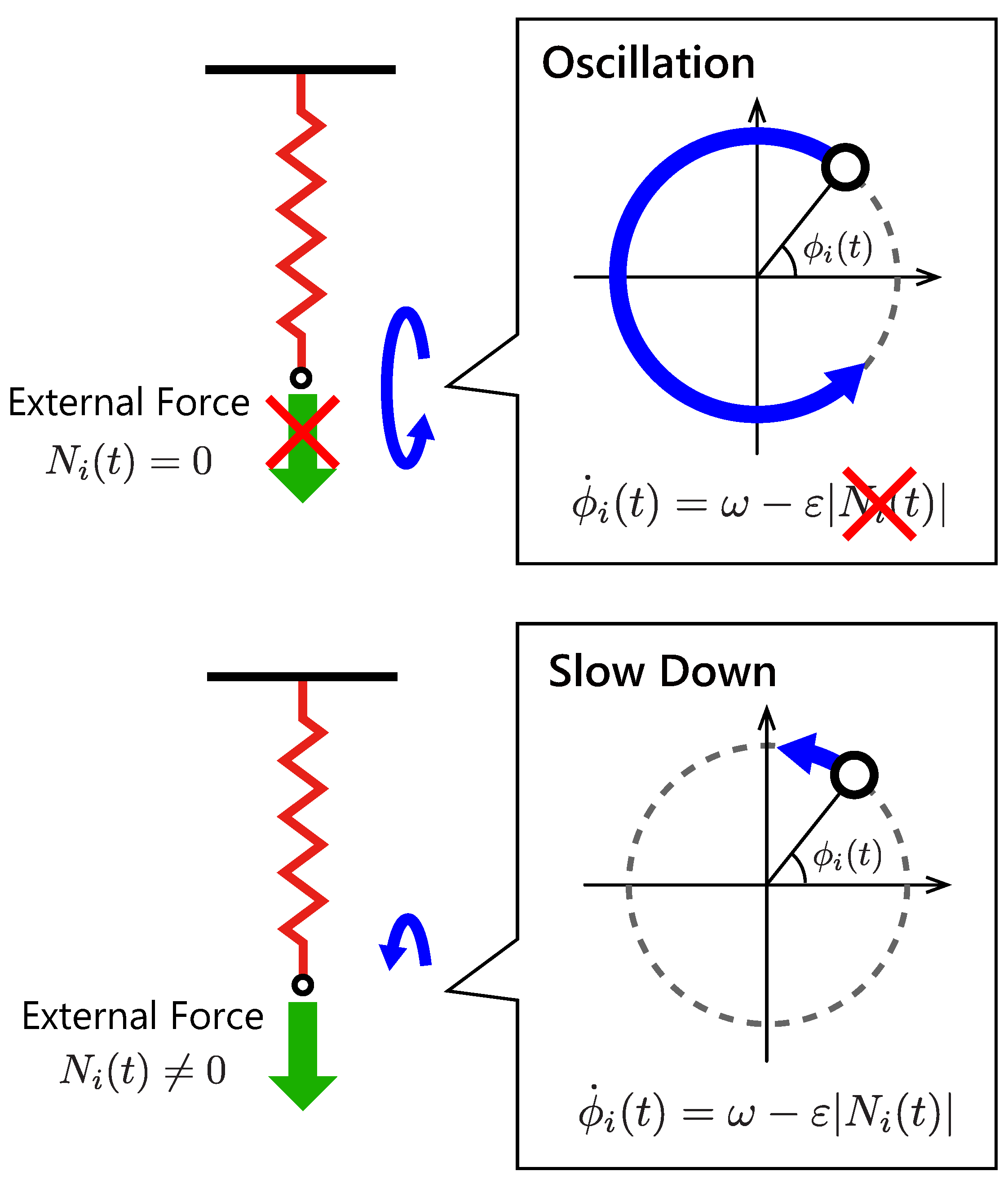
Figure 3 illustrates the feedback effect in the proposed controller. When the controller does not sense forces , it oscillates the body in a constant frequency by driving the linear actuator. If the controller senses a non-zero internal force in the spring–damper, then the local feedback term is activated, and it slows down the oscillation. To prevent the reverse rotation of the phase , we determine the sensory gain so as to satisfy a condition with an expected upper limit of the internal force . In this paper, the expected upper limit of the internal force was estimated through trial and error.
In other words, the proposed controller expressed by Equation (1) delays the phases when there are unmatched forces to the actuator movement. As a result, the controllers converge on a steady state that decreases the unmatched forces in each actuator.
3. Linear Spring–Mass–Damper System
This section describes simulations to investigate fundamental features of the proposed controller.
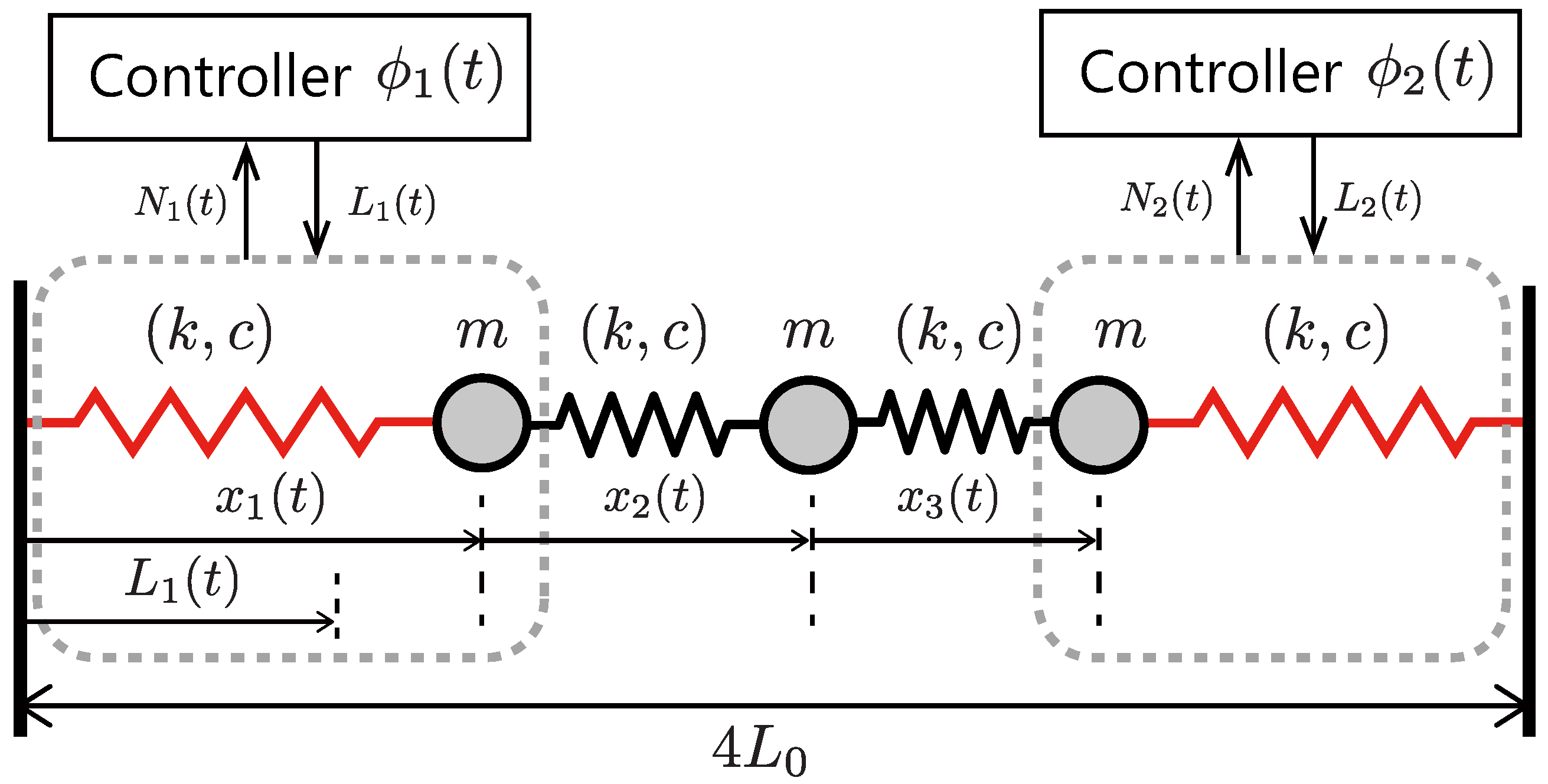
The simulation setting is illustrated in Figure 4. The system is composed of three masses and four linear spring–dampers and has three vibration modes corresponding to each resonant frequency. In this simulation, we show an adaptability to changes in the vibration frequency and the body parameter. We compare the analytically derived resonant frequencies and the simulated ones.
3.1. Resonance Frequency Analysis
For simplicity, we assume that the spring constants of all the springs, the natural length, and the weights of the masses are equal (, , ), and the effect of the damper is sufficiently small. Let a new state variable . Then the model in Figure 4 is formulated as follows:
By using eigenvalue analysis of the state matrix of the model expressed by Equation (4), the resonant frequencies of the mechanical dynamics can be estimated as
Next, we show some simulation results that the proposed controller excites these modes adaptively and automatically.
3.2. Simulations of Resonance Mode Excitation
We conducted two simulations with two different spring constants . In each case, simulations are performed iteratively by changing the initial phase difference and the intrinsic angular velocity . The control input is given by Equation (1), and we set the following parameters equal for all spring–dampers and actuators:
We set the initial states of each controller
and change in , and in .
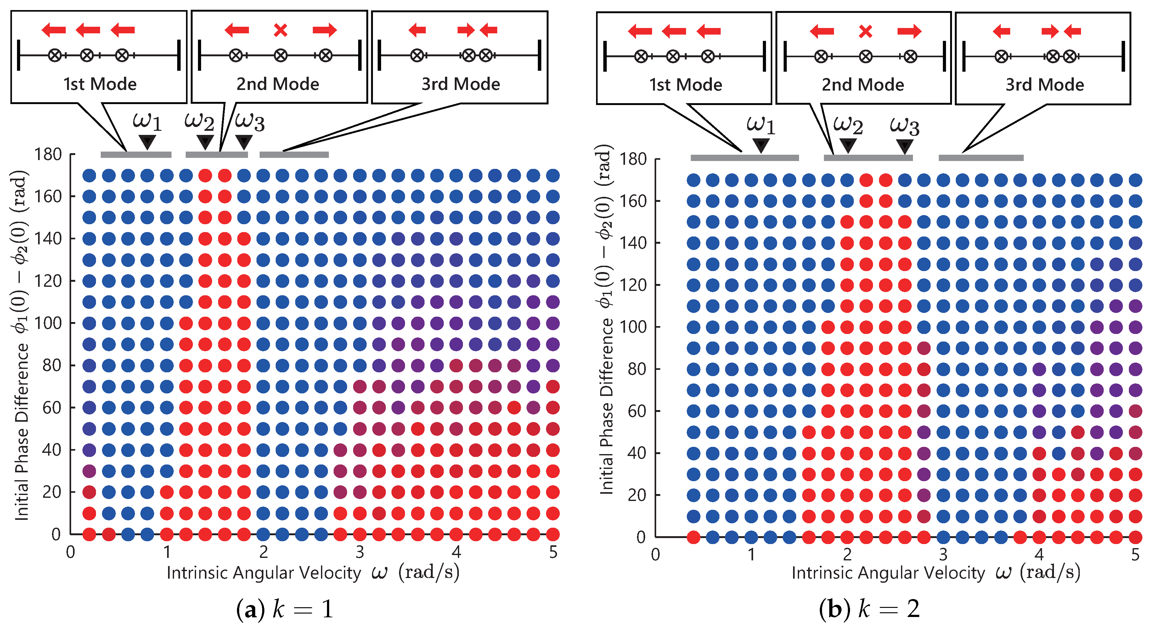
Figure 5a,b show the simulation results with different spring constants . The color of bullet denotes the phase difference of converged solutions of two controllers. The blue bullet denotes that the solutions of the two controllers are in an in-phase manner, and the red bullet denotes that the solutions are in an anti-phase manner. The triangles at the top of the graph indicates the resonant frequencies that is analytically derived. In these figures, the phase differences of converged solutions change as the intrinsic angular velocity increases. In Figure 5a with , the first transition occurs at around , and the second is at around . In Figure 5b with , the first is at around , and the second is at around . Each solution converged to the resonant modes and achieves transitions between the modes:
as illustrated in the upper of Figure 5a,b.
3.3. Discussion of the Simulation
As shown in Figure 5a,b, the proposed controller generated the resonant modes and achieved the transitions between the modes automatically. Table 1 shows the analytically derived resonant frequencies and the simulated ones. Based on the tables, the three modes in Figure 5a,b were excited around the analytically derived frequencies . This result shows that the proposed controller expressed by Equation (1) automatically generates versatile resonant modes by selecting a scholar control parameter.
However, in Figure 5a,b, at small or large frequencies, the solutions depends on the initial values. These failures were due to the small sensor values. At small frequencies, the internal forces for feedback were small due to the slow movement of the masses, and at large frequencies, the internal forces were also small due to the low amplitude motion due to the gain characteristic of the mechanical structure. Moreover, in Table 1a,b, as the frequency increased, particularly in the 3rd mode, the analytical and simulated results were in disagreement. It is assumed that these disagreement are due to the assumption that the natural length is constant in the analysis. In the simulation, the frequency of the output motion becomes smaller than because the controller has a feedback term that delays the phase rotation.
4. Gait Generation in Legged Robot Model
This section demonstrates some simulations with a simple legged robot model to evaluate the proposed controller.
The model of the robot is the simplified sagittal plane model for a quadruped robot [27], which has two known resonant modes. We show that the simple robot model with two proposed control modules can generate versatile gaits that can be explained by resonant oscillation.
4.1. Model Formulation
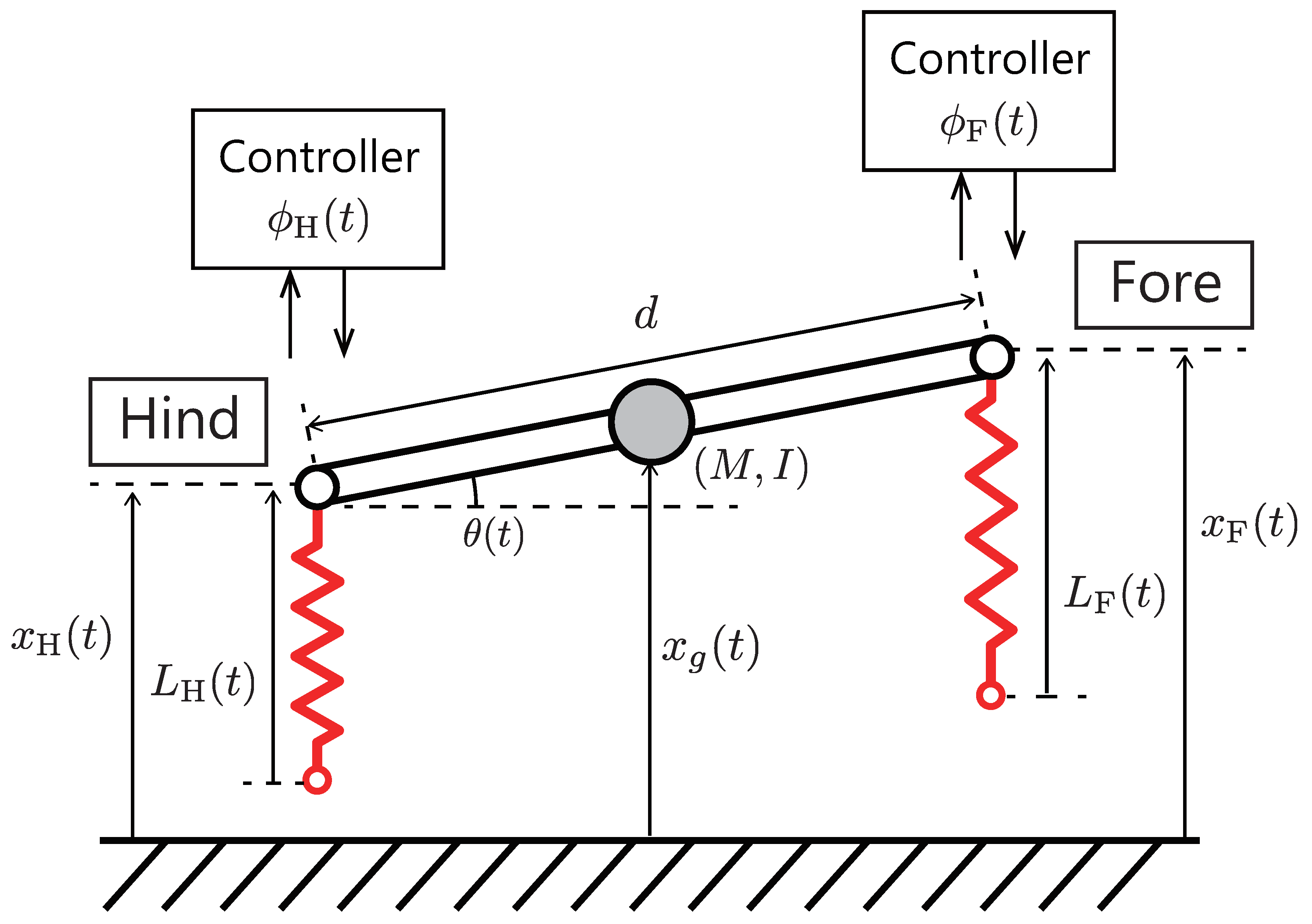
Figure 6 shows an overview of a simplified legged robot model moving on the vertical (sagittal) plane. We adopt a simple model that has two known resonant modes for a mode analysis as mentioned later. This model is based on the simplified sagittal plane model [27], which can be considered as a quadruped robot model in two-dimensional space (side view). This model composed of fore and hind springy legs, and a rigid spine that joins these legs. Although the robot is quadruped, we assume that the motions of the left legs is mirrored to the right ones, and the legs are always perpendicular to the ground. The model is formulated as follows:
where M and I denotes the body mass and moment of inertia, d is the body length, and g is the gravity constant. is the robot posture, and is the position of the center of gravity. and the hip heights and satisfy the following conditions:
The internal forces in the legs and are computed as follows:
where we assume that the viscoelastic parameters k and c are identical in each leg.
To describe the flight phase of legs, we defined a switching function
The natural length of fore and hind springy legs are as follows:
The phases of the legs are determined by two controllers as follows:
Here, we assume that the mass of the feet tip is sufficiently small. Thus, the internal forces and in each leg are zero when the corresponding leg leaves from the ground.
4.2. Resonance Frequency Analysis
In this section, we adopt a few assumptions for the resonant frequency analysis. We assume that the feet of the robot model are fixed on the ground, all of the natural lengths are equal (), and the effect of the damper is sufficiently small. Assuming that the infinitesimal angle , we have a linearized robot model around the origin
Let a new state variable . Based on Equations (9) and (19), the model in Figure 4 is formulated as follows:
By using eigenvalue analysis of the state matrix of the model expressed by Equations (20) and (21), the resonant frequencies can be estimated as
where we assume that the rigid spine is a uniform rod (). The frequency corresponds to the pronk gait, the fore and hind legs are in an in-phase manner, and the is the bound gait, the fore and hind legs are in an anti-phase manner.
4.3. Simulations of Resonance Mode Excitation
Finally, we show the simulations with the legged robot model.
The simulations are performed iteratively by changing the initial phase difference and the intrinsic angular velocity . We set the following parameters equal for all spring–dampers and actuators:
We set the initial states of each controller
and change in and in .
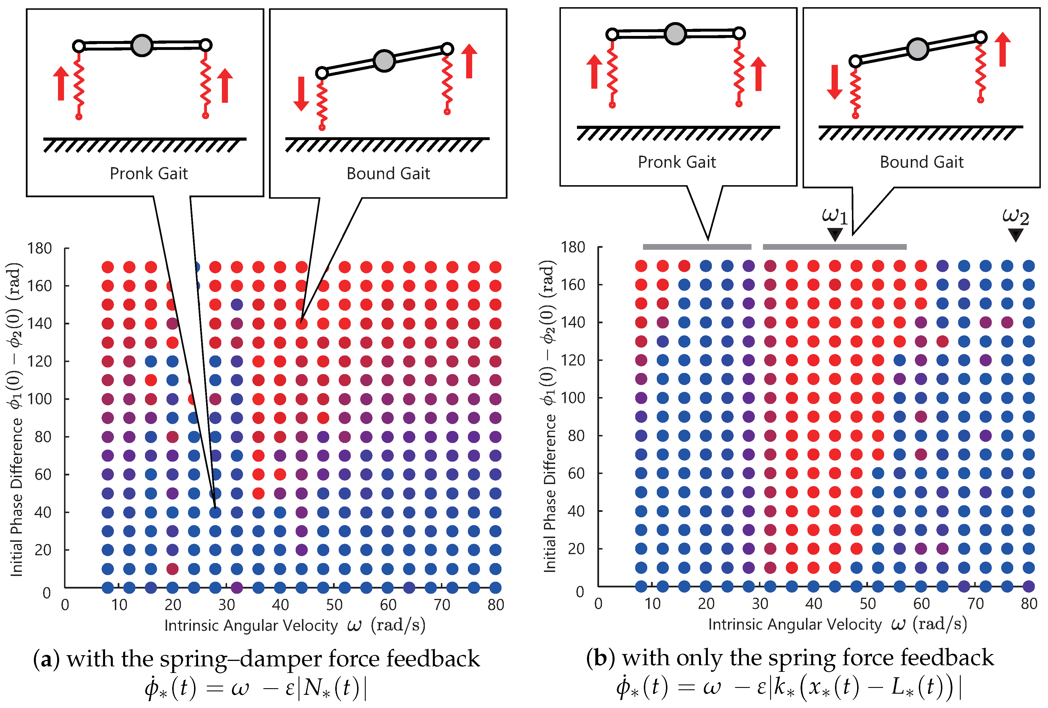
Figure 7a shows the simulation result. Similar to the previous simulations, the color of the bullet denotes the phase difference of the converged solutions of the two controllers. The blue bullet denotes the solutions that the two legs are in an in-phase manner, and the red bullet are the solutions in an anti-phase manner.
From this result, we observe that the resulting phase difference is sensitive to the choice of the initial values—not to the choice of the control parameter . This result means that there is no steady limit cycle or gaits. Now, let us consider selecting the motion pattern by choosing the control parameter and make it insensitive to the initial values (make the limit cycle steady). For this purpose, we propose a modification to the controller in the next subsection.
4.4. Modification to the Controller
Based on the result above, we apply an modification to the controllers. In this modification, we alter the sensory information (the spring–damper force in Equation (18)) to the spring force as follows:
Although this modification was discovered by chance, some evidence in conventional research agrees with this result (see the discussion).
Figure 7b shows the result with the modified controller. The triangles at the top of graph indicates the resonant frequencies and that are analytically derived. Each solution converged to the resonant modes, as illustrated in the upper figure. As shown in these figures, the phase differences of converged solutions change as the intrinsic angular velocity increases. From the upper figure, the in-phase gait is generated in , and the anti-phase is generated in . In other words, at around , the following gait transition occurs:
4.5. Discussion of the Simulation
Based on Figure 7a, when we use the spring–damper force feedback, we could not generate steady limit cycles. Based on Figure 7b, the proposed controller achieved steady gait generation and transition automatically. However, at small frequencies , the solutions depend on the initial values for the same reasons as Figure 5. This model might explain the mechanism for the gait transition between the pronk and bound observed in gazelles.
By comparing these two results, Figure 7a,b, in the legged model (a nonlinear system with the switching between the the swing and stance states), the spring force feedback is more effective than the spring–damper force feedback for steady gait generation. Although this modification was found heuristically, there is evidence in conventional research that agrees with our result. In biology, it is well known that the muscle spindle receptor, which contributes to the stretch reflex in animals, has two feedback pathways: one sends muscle displacement information, and the other one sends muscle velocity [28]. Related to the function of the pathways, one study [29] showed that the sensitivity of the muscle displacement was mainly activated during periodic motions in walking and running cats. In contrast, the receptor for the muscle velocity was deactivated during these periodic motions. Similar agreement was found in our recent study [30]. In that study, we constructed a biological model of the stretch reflex circuit and confirmed that the sensory feedback of the muscle displacement generates resonant modes. These results suggest that the displacement feedback is effective in generating steady resonant modes.
Table 2 shows the resonant frequencies, which were analytically derived, and the excited frequencies in the simulations. There are large disagreements between the analytical and simulated frequencies: the simulated frequencies are almost half of the analytical ones. These disagreements are due to the modeling error based on the assumption that the feet of the robot model are fixed on the ground: the flight phase was not considered in the analysis. A similar phenomenon has also been reported in [26].
5. Discussion
From the results above, an extremely simple controller based on reflex can automatically generate versatile motion patterns. This phenomenon can be explained by the controllers–body integration based on resonant oscillation.
The results in this paper provide a few suggestion for understanding animals’ motor function. First, the results suggest that the control from the upper central is not necessary required, and the physical interaction of the local reflex controllers are crucial to excite the periodic motions as resonant modes. Second, for generating the synchronized periodic motions, the muscle displacement information is more important than the muscle velocity information. The large amplitude motion at resonant modes helps to increase stride length. These results suggest that the simple and local reflex strategy in animals contribute a motion pattern generation by exploiting the physical interaction through the body dynamics.
Compared with a conventional controller [14] that formulates as follows:
the proposal (1) does not use any information of current phase . Related to this approach, our conventional controller [31], which uses the current phase , also generates the various resonant modes. Although various experiments show that actual animals use the current phase information during walking (reactions to ground reaction forces are changed according to the leg phase), this response is the behavior of whole systems, including neural circuits and inter-limb neural connection. The proposed method without the current phase information can explain the fundamental stabilization ability of the reflex strategy itself.
6. Conclusions
In this paper, we propose an extremely simple controller based on reflexes and investigate the controllers–body integration based on resonant oscillation. This paper shows that the simple controller can automatically generate versatile motion patterns, as animals do. This reflex controller syncs the multiple controllers and the whole body dynamics with the resonant modes by only physical interaction. In the simulations, the spring–mass–damper system shows an adaptability to changes in the vibration frequency and the body parameter. By selecting a frequency of the controller, seamless transitions between the resonant modes are achieved. In the legged robot model, we show a limitation of the proposed method due to the nonlinearity, and an alternative method to replace the sensory value with a spring force is proposed. Finally, the robot model with the simple controller generates the gazelles’ gaits just by choosing a control parameter of “speeding up or down.” This result suggest that the muscle displacement information is more important than the muscle velocity information for gait generation and resonant mode excitation.
Author Contributions
Y.M. designed the study, contributed to analysis, and wrote the initial draft of the manuscript. M.I. contributed to the interpretation of data, and assisted in the preparation of the manuscript. All authors approved the final version of the manuscript, and agree to be accountable for all aspects of the work in ensuring that questions related to the accuracy or integrity of any part of the work are appropriately investigated and resolved.
Funding
This research was mainly supported by funding from the Tateisi Science and Technology Foundation, JST CREST, and Grant-in-Aid for JSPS Research Fellow JP17J00601. The founding sponsors had no role in the design of the study; in the collection, analyses, or interpretation of data; in the writing of the manuscript; or in the decision to publish the results.
Acknowledgments
This research was mainly supported by funding from the Tateisi Science and Technology Foundation and Grant-in-Aid for JSPS Research Fellow JP17J00601.
Conflicts of Interest
The authors declare no conflict of interest.
References
- Muybridge, E. Animal Locomotion; Da Capo Press: New York, NY, USA, 1969. [Google Scholar]
- Hildebrand, M. Symmetrical gaits of horses. Science 1965, 150, 701–708. [Google Scholar] [CrossRef] [PubMed]
- Hoyt, D.F.; Taylor, C.R. Gait and the energetics of locomotion in horses. Nature 1981, 292, 239. [Google Scholar] [CrossRef]
- Shik, M.L.; Severin, F.; Orlovskiĭ, G. Control of walking and running by means of electric stimulation of the midbrain. Biofizika 1965, 11, 659–666. [Google Scholar]
- Hiebert, G.W.; Pearson, K.G. Contribution of sensory feedback to the generation of extensor activity during walking in the decerebrate cat. J. Neurophys. 1999, 81, 758–770. [Google Scholar] [CrossRef] [PubMed]
- Pearson, K.; Ekeberg, Ö.; Büschges, A. Assessing sensory function in locomotor systems using neuro-mechanical simulations. Trends Neurosc. 2006, 29, 625–631. [Google Scholar] [CrossRef] [PubMed]
- Zehr, E.P.; Stein, R.B. What functions do reflexes serve during human locomotion? Prog. Neurobiol. 1999, 58, 185–205. [Google Scholar] [CrossRef]
- Nashner, L. Adapting reflexes controlling the human posture. Exp. Brain Res. 1976, 26, 59–72. [Google Scholar] [CrossRef] [PubMed]
- Sinkjaer, T.; Andersen, J.B.; Larsen, B. Soleus stretch reflex modulation during gait in humans. J. Neurophys. 1996, 76, 1112–1120. [Google Scholar] [CrossRef] [PubMed]
- Dyhre-Poulsen, P.; Simonsen, E.B.; Voigt, M. Dynamic control of muscle stiffness and H reflex modulation during hopping and jumping in man. J. Phys. 1991, 437, 287–304. [Google Scholar] [CrossRef]
- Jones, G.M.; Watt, D. Observations on the control of stepping and hopping movements in man. J. Phys. 1971, 219, 709–727. [Google Scholar] [CrossRef]
- Rosendo, A.; Liu, X.; Shimizu, M.; Hosoda, K. Stretch reflex improves rolling stability during hopping of a decerebrate biped system. Bioinspir. Biomim. 2015, 10, 016008. [Google Scholar] [CrossRef] [PubMed]
- Ijspeert, A.J. Central pattern generators for locomotion control in animals and robots: A review. Neural Netw. 2008, 21, 642–653. [Google Scholar] [CrossRef] [PubMed]
- Owaki, D.; Kano, T.; Nagasawa, K.; Tero, A.; Ishiguro, A. Simple robot suggests physical interlimb communication is essential for quadruped walking. J. R. Soc. Interface 2013, 10, 20120669. [Google Scholar] [CrossRef] [PubMed]
- McGeer, T. Passive dynamic walking. Int. J. Robot. Res. 1990, 9, 62–82. [Google Scholar] [CrossRef]
- Collins, S.; Ruina, A.; Tedrake, R.; Wisse, M. Efficient bipedal robots based on passive-dynamic walkers. Science 2005, 307, 1082–1085. [Google Scholar] [CrossRef] [PubMed]
- Owaki, D.; Osuka, K.; Ishiguro, A. On the embodiment that enables passive dynamic bipedal running. In Proceedings of the Robotics and Automation 2008 IEEE International Conference, Pasadena, CA, USA, 19–23 May 2008; pp. 341–346. [Google Scholar]
- Osuka, K.; Nakatani, K.; Sugimoto, Y.; Akazawa, T. On existence of multi-legged passive dynamic walking-one-legged, tow-legged, four-legged, six-Legged. In Proceedings of the Symposium on Control Theory, Sapporo, Japan, 5–7 September 2007; pp. 95–98. [Google Scholar]
- Nakatani, K.; Sugimoto, Y.; Osuka, K. Demonstration and analysis of quadrupedal passive dynamic walking. Adv. Robot. 2009, 23, 483–501. [Google Scholar] [CrossRef]
- Karssen, J.D.; Haberland, M.; Wisse, M.; Kim, S. The effects of swing-leg retraction on running performance: analysis, simulation, and experiment. Robotica 2015, 33, 2137–2155. [Google Scholar] [CrossRef]
- Poulakakis, I.; Papadopoulos, E.; Buehler, M. On the stability of the passive dynamics of quadrupedal running with a bounding gait. Int. J. Robot. Res. 2006, 25, 669–687. [Google Scholar] [CrossRef]
- Sprowitz, A.T.; Tuleu, A.; Ijspeert, A.J. Kinematic primitives for walking and trotting gaits of a quadruped robot with compliant legs. Front. Comput. Neurosci. 2014, 8, 27. [Google Scholar] [PubMed]
- Cao, Q.; Poulakakis, I. Passive quadrupedal bounding with a segmented flexible torso. In Proceedings of the 2012 IEEE/RSJ International Conference on Intelligent Robots and Systems (IROS), Vilamoura, Portugal, 7–12 October 2012; pp. 2484–2489. [Google Scholar]
- Kurita, Y.; Matsumura, Y.; Kanda, S.; Kinugasa, H. Gait patterns of quadrupeds and natural vibration modes. J. Syst. Des. Dyn. 2008, 2, 1316–1326. [Google Scholar] [CrossRef]
- Reis, M.; Iida, F. An energy-efficient hopping robot based on free vibration of a curved beam. IEEE Trans. Mech. 2014, 19, 300–311. [Google Scholar] [CrossRef]
- Reis, M.; Yu, X.; Maheshwari, N.; Iida, F. Morphological computation of multi-gaited robot locomotion based on free vibration. Artif. Life 2013, 19, 97–114. [Google Scholar] [CrossRef] [PubMed]
- Park, H.W.; Chuah, M.Y.; Kim, S. Quadruped bounding control with variable duty cycle via vertical impulse scaling. In Proceedings of the 2014 IEEE/RSJ International Conference on Intelligent Robots and Systems (IROS 2014), Chicago, IL, USA, 14–18 September 2014; pp. 3245–3252. [Google Scholar]
- Boyd, I. The isolated mammalian muscle spindle. Trends Neurosci. 1980, 3, 258–265. [Google Scholar] [CrossRef]
- Prochazka, A.; Hulliger, M.; Trend, P.; Dürmüller, N. Dynamic and static fusimotor set in various behavioural contexts. In Mechanoreceptors; Springer: Heidelberg/Berlin, Germany, 1988; pp. 417–430. [Google Scholar]
- Masuda, Y.; Ishikawa, M. Muscles Excite and Synchronize Themselves through Their Intrinsic Dynamics. In Proceedings of the 2017 International Symposium on Nonlinear Theory and its Applications, Cancun, Mexico, 4–7 December 2017. [Google Scholar]
- Masuda, Y.; Minami, Y.; Ishikawa, M. Actuator Synchronization for Adaptive Motion Generation without Any Sensor or Microprocessor. In Proceedings of the 2017 Asian Control Conference, Gold Coast, Australia, 17–20 December 2017. [Google Scholar]
Figure 1.
Concept of the proposed reflex controller. The simple and fast-response reflex controllers in each part of the robot allows the robot to sync itself by only physical interaction through the whole body dynamics.
Figure 1.
Concept of the proposed reflex controller. The simple and fast-response reflex controllers in each part of the robot allows the robot to sync itself by only physical interaction through the whole body dynamics.

Figure 2.
Overview of the proposed controller module. Each module is composed of an actuator part, which is modeled as a linear actuator with a spring–damper, and a controller part, which provides oscillation and a reflex function. If the controller module is subjected to an external force from the robot body and environment, then the controller senses an internal force in the spring–damper and adjusts the natural length of the actuator part.

Figure 3.
Feedback effect in the proposed controller. When the controller does not sense forces, it oscillates the body in a constant frequency by driving the linear actuator; however, if the controller senses a non-zero internal force in the spring–damper, then it slows down the oscillation.
Figure 3.
Feedback effect in the proposed controller. When the controller does not sense forces, it oscillates the body in a constant frequency by driving the linear actuator; however, if the controller senses a non-zero internal force in the spring–damper, then it slows down the oscillation.

Figure 4.
Simulation setting of spring–mass–damper system. Two control modules (red spring– dampers) are in the left and right. Passive springs–dampers (black spring–dampers) are in the middle that transmit the physical interaction.
Figure 4.
Simulation setting of spring–mass–damper system. Two control modules (red spring– dampers) are in the left and right. Passive springs–dampers (black spring–dampers) are in the middle that transmit the physical interaction.

Figure 5.
Simulation result of the spring–mass system. Figure 5a shows a result with , and Figure 5b shows a result with . The blue bullet denotes that the solutions of the two controllers are in an in-phase manner, and the red bullet are the solutions in an anti-phase manner. The triangles at the top of the graph indicates the resonant frequencies that is computed in advance by mathematical analysis.

Figure 6.
The simplified sagittal plane model [27] of a quadruped robot. The model assumes that the motions of the left side of the body is mirrored to right. The proposed controller are applied to the fore and hind legs.
Figure 6.
The simplified sagittal plane model [27] of a quadruped robot. The model assumes that the motions of the left side of the body is mirrored to right. The proposed controller are applied to the fore and hind legs.

Figure 7.
Simulation result of the legged robot model. Figure 7a shows the simulation result with the spring-damper force feedback, and Figure 7b shows the simulation result with the modified controller using only spring force feedback. The blue bullet denotes the solutions that the two legs are in an in-phase manner, and the red bullet denotes that the solutions are in an anti-phase manner. The triangles at the top of the graph indicates the resonant frequencies and , which are analytically derived.


Table 1.
Analysis vs. simulation.
| 1st mode | 2nd mode | 3rd mode | |
| Analysis | |||
| Simulation | |||
| 1st Mode | 2nd Mode | 3rd Mode | |
| Analysis | |||
| Simulation | |||
Table 2.
Analysis vs. simulation.
| 1st Mode | 2nd Mode | |
|---|---|---|
| Analysis | ||
| Simulation |
© 2018 by the authors. Licensee MDPI, Basel, Switzerland. This article is an open access article distributed under the terms and conditions of the Creative Commons Attribution (CC BY) license (http://creativecommons.org/licenses/by/4.0/).
Share and Cite
MDPI and ACS Style
Masuda, Y.; Ishikawa, M. Simple Reflex Controller for Decentralized Motor Coordination Based on Resonant Oscillation. Robotics 2018, 7, 23. https://doi.org/10.3390/robotics7020023
AMA Style
Masuda Y, Ishikawa M. Simple Reflex Controller for Decentralized Motor Coordination Based on Resonant Oscillation. Robotics. 2018; 7(2):23. https://doi.org/10.3390/robotics7020023
Chicago/Turabian StyleMasuda, Yoichi, and Masato Ishikawa. 2018. "Simple Reflex Controller for Decentralized Motor Coordination Based on Resonant Oscillation" Robotics 7, no. 2: 23. https://doi.org/10.3390/robotics7020023
Note that from the first issue of 2016, this journal uses article numbers instead of page numbers. See further details here.