VETO: An Immersive Virtual Environment for Tele-Operation
by
 and
and
Brandon Wilson
1, 
Matthew Bounds
1,
David McFadden
1,
Jace Regenbrecht
1,
Loveth Ohenhen
1,
Alireza Tavakkoli
1,2,* and
Donald Loffredo
3 1
Department of Computer Science, University of Houston-Victoria, Victoria, TX 77901, USA
2
Computer Science and Engineering Department, University of Nevada, Reno, NV 89557, USA
3
Department of Psychology, University of Houston-Victoria, Victoria, TX 77901, USA
*
Author to whom correspondence should be addressed.
Robotics 2018, 7(2), 26; https://doi.org/10.3390/robotics7020026
Submission received: 12 April 2018
/
Revised: 24 May 2018
/
Accepted: 4 June 2018
/
Published: 8 June 2018
Abstract
:This work investigates an over-arching question: how can an immersive virtual environment be connected with its intelligent physical counterpart to allow for a more efficient man-machine collaboration. To this end, an immersive user interface for the purpose of robot tele-operation is designed. A large amount of sensory data is utilized to build models of the world and its inhabitants in a way that is intuitive to the operator and accurately represents the robot’s real-world state and environment. The game client is capable of handling multiple users, much like a traditional multiplayer game, while visualizing multiple robotic agents operating within the real world. The proposed Virtual Environment for Tele-Operation (VETO) architecture is a tele-operation system that provides a feature-rich framework to implement robotic agents into an immersive end-user game interface. Game levels are generated dynamically on a Graphic Processing Unit or GPU-accelerated server based on real-world sensor data from the robotic agents. A set of user studies are conducted to validate the performance of the proposed architecture compared to traditional tele-robotic applications. The experimental results show significant improvements in both task completion time and task completion rate over traditional tools.
1. Introduction
The tele-operation of robotic platforms plays a vital role in space exploration, military reconnaissance, undersea operations, robotic surgery, training of personnel, and search and rescue operations in unsafe locations. Despite the push for more autonomous behavior of robot agents, tele-operation will still be necessary as a sort of “default mode” for users, both to fix and to prevent errors caused by autonomous behavior as well as to boost the user’s trust of the robot agent [1]. In addition, the task of robot tele-operation will become more commonplace as more and more viable robot platforms become more affordable [2]. However, this could be a difficult task with traditional robot control schemes due to information overload for the end-user in complex scenes [3].
In order to provide enough information for operators to effectively and efficiently control a robot remotely, the end user must have access to real-world visual odometry, positional and environmental map data, as well as any laser range finder, sonar, or other sensor data used by the robot for obstacle detection and localization. In addition, this data is further increased when multiple collaborative robots are considered. Traditional robot control schemes employ simple user interfaces to display information as a Heads-Up Display (HUD) [1]. This traditional user interface is used to offer information about both the robot’s current state as well as the state of its environment.
Games are traditionally thought of as a non-scientific medium of entertainment [4]. However, under the hood games are an immersive medium rendered through 3D virtual environments. In addition, these mediums are becoming more and more immersive through the advent of Virtual Reality (VR) Head-Mounted Displays (HMDs). Furthermore, these HMDs are becoming more and more commercially available [5]. VR will play an increasingly important role in tele-operation due to the synergy between robots and VR technology [6]. VR provides the user with increased immersion and enables the user to interact directly with their environment in an intuitive way. In addition, the robot provides a source of force feedback to any given tele-operation system. In theory, as an immersive and 3D medium capable of intuitive user interaction, a VR-enabled game is an ideal medium for the tele-operation of remote robotic platforms. However, there are many problems that must be addressed in order to utilize a game as a user interface for robot tele-operation. Below, we present the main contributions of this paper that address the outlined challenges of producing effective immersive virtual environments that are useful for the tele-operation of remote robotic agents.
1.1. Unreal Engine 4 Integration
First, a platform for the rendering, animation, and physics is necessary for the interface. For this research, the platform of choice for the implementation of the virtual reality environment was Epic Game’s Unreal Engine 4 [7]. The game engine, developed by Epic Games Inc., is comprised of an advanced graphics rendering engine, a sound engine, and physics and animation engines. This game engine is capable of delivering unparalleled performance in 3D realistic gameplay, simulation and visualization [8]. Unreal Engine 4 (UE4), the latest major version of the engine, was released in April 2014. New to this release are several completely redesigned architectures that have been utilized in this work. In addition, UE4 is a pioneer in virtual reality technology and its applications, and supports many commercial HMDs out of the box. In order to utilize the UE4 game engine for controlling physical agents, a number of new functionalities must be developed and integrated within the base engine. In this work, a range of functionalities including computer vision, robotics control frameworks, and parallel processes in support of the entire system are introduced and added to UE4.
1.2. The VETO Architecture
Next, an architecture must be utilized to efficiently communicate data between the robot agents and their end-user robot interface. Thus, the Virtual Environment for Tele-Operation (VETO) architecture was developed and implemented in this work. This architecture provides easy integration of robot clients and their unique robot interfaces into a GPU-accelerated High Performance Computing (HPC) server, as well as an end-user dynamic and immersive virtual reality-enabled 3D environment provided through UE4. The architecture allows for the offloading of computationally-intensive tasks to the HPC server, which facilitates communications between the end-user’s UE4 game client and the real-world robot platform. In this way, users are virtually in the same environment as the robot, and can intuitively interact with both the robot and it’s environment. User input is then translated to real-world actuators on the robot platform.
1.3. Networking Communication
As previously stated, the VETO architecture supports multiple robot clients, a centralized HPC server, and a variety of end-user clients. Therefore, a standard of network communication must be established and utilized by each of these network components. Moreover, it is ideal for the same network technology to be is used throughout the VETO architecture. Therefore, the CrossSock networking API was developed as a result of this work [9]. CrossSock is a cross-platform, lightweight, and header-only high-level solution for developing client-server architectures. As a header-only and cross-platform Application Programmer’s Interface (API), it is easy to develop network applications on any UNIX or Windows-based operating system. This allows for the integration of a breadth of robotic platforms as well as the integration with all of the platforms that UE4 supports for the end-user interface.
1.4. Dynamic Level Generation
Another major concern when considering an immersive virtual environment is the generation and placement of 3D meshes to fill the scene. At this time, this work is designed to operate in a fully observable environment that has been scanned beforehand. As such, the VETO architecture automatically generates walls and rooms for the end-user to explore. To add immersion, an In-Game Editor (IGE) has been provided in the VETO’s end-user game interface to place pre-built models of common objects into the scene. This setup is efficient in terms of performance, but requires manual manipulation of dynamic objects in the scene.
2. Literature Review
There has been much work done in the past to improve end-user effectiveness for the purpose of remote robot tele-operation. This section explores some of this work as it relates to the field of robotic tele-operation.
The simplest and most traditional approach to robot tele-operation is through the direct manual control of the robotic platform through a direct video feed. Shiroma et al. [10] investigated the optimal camera position and orientations for this approach for the purpose of remotely-operated search and rescue robots. They found that a third person camera, positioned such that the robot platform is in the center of its view, is most effective as it provides a clear view of the robot’s immediate surroundings on all sides. Farkhatdinov et al. [11] seeked to further this approach by providing a study of speed, position and command strategies and their performances. In addition, this work improveds on the raw visual feedback with the inclusion of text and haptic feedback to provide additional information to the end-user. These traditional approaches do not provide 3D environmental data, which causes a penalty to user immersion and the overall efficiency of the operator.
Several approaches have been used to augment the traditional visual-based approach with 3D data on a contained scale. Nielsen et al. [3] proposed combining a camera feed with a 2D map interpretation, as well as a 3D interpretation of the 2D map with the projection of the 2D camera feed into 3D space. This approach allows for improved spacial awareness of operators. However, the environmental data is limited to 2D data outside of the current camera’s perspective. This approach would benefit from the decoupling of 3D data from the robots current location, as this would allow for the independent exploration of the virtual environment by the operator. Tsumaki et al. [12] utilized a virtual environment to visualize the reachability of a robot manipulator. In their method, visualization is provided through a deformable mesh that visualizes the 6-dimensional reachability data of the 6 degrees of freedom manipulator in a way that is intuitive to the user. However, this approach iss limited in scale to that of a single manipulator, and does not include the robot’s surrounding environment.
There are several network-related challenges for multi-robot and multi-user tele-operation systems. Wang and Liu [13] described an interactive control scheme for the tele-operation of a robot platform over the internet. The system supports manual control as well as high-level linguistic commands, and has been tested at over 1500 km from the end-user to the robot agent. Suzuki et al. [14] expanded on network communication through a system that supports multiple robot agents through a client-server architecture. In addition, this system includes three levels of operation to provide flexibility in the robot control scheme. The proposed CrossSock and the VETO architecture in this paper expand on this work by allowing for multiple end-clients in addition to multiple robot agents, all of which can exist in different physical locations and interact in the same virtual environment over the internet. In addition, all of these works lack the generalization necessary to easily add robot agents to the system. The VETO architecture includes a framework to allow easy addition of support for each robot’s unique robot interface, as well as all of the visualization necessary for the end-user’s virtual environment.
As previously stated, there are several challenges to the use of real-time odometry for the purpose of tele-operation. Dryanovski et al. [15] employed increasingly affordable RGB-D cameras as well as a novel uncertainty measure for the purpose of fast, real-time visual odometry. This approach is capable of closing small-scale loops in an indoor environment without the need for traditional localization or a co-processor for acceleration. However, this approach requires an RGB-D camera, which is unavailable and not preferred on many low-power robot agents, such as drones and planetary rovers. Lentaris et al. [16] proposed the utilization of an space-worthy Field Programmable Gate Array (FPGA) co-processor to accelerate visual odometry to one order of magnitude faster than the software utilized by contemporary Mars rovers. This approach requires a FPGA co-processor to be added to the robot itself, which increases its weight and cost. In addition, this approach has scalability issues when considering a system with multiple robot agents. As such, the VETO architecture uses a general purpose accelerator and off-boards the more intensive tasks to an HPC server. In a similar scenario, this HPC server could exist as a medium between the planetary rover and its operator, such as on an orbiting satellite.
Finally, there are several approaches to the visualization of robot agents, their sensors, and their real-world environments in virtual reality. Monferrer and Bonyuet [17] and Lin and Kuo [18] both seeked to present a set of guidelines to define the ideal virtual reality interface for robot tele-operation. Moreover, both works provided an implementation of a virtual reality interface used to control an underwater robot. However, each of these work’s visualizations are dated, and neither of their approaches addressed dynamic level generation as they were both simulations of a known environment. In addition, both approaches used a single user and single robot system, which was specialized to the specific robotic platform utilized in their respective works. More recent work around the tele-presence and tele-operation of robot platforms includes Xinxing et al. [19], in which a master-slave system for controlling a construction robot was described. However, this system is limited in that it is designed to work in a known environment and specialized towards a single robot. Baizid et al. [20] described a multi-robot system named ViRAT and included a VR end-user environment. However, this work focused on tele-operation over tele-presence, and did not provide any quantitative or qualitative results pertaining towards the VR environment itself.
3. Immersive User Interfaces and Virtual Environments for Tele-operation
Two factors are of vital importance when considering the application of a virtual reality environment and the immersion afforded by it for the tele-presence and tele-operation of robotic agents. These factors were defined by Steuer as the depth of information and the breadth of information [21]. The depth of information relates to the amount and quality of data received by the user, contributing to the user’s perception of, and interactivity with, the virtual environment. The breadth of information, on the other hand, relates to the number of sensory systems simultaneously present that acquire data and information to facilitate the interaction between the virtual environment and the user. Therefore, the depth of information can be viewed as the dimension of human perception of the virtual environment, while the breadth of information relates to the perception of the virtual environment of its users. The goal of the proposed VETO architecture is to investigate the mathematical and computational foundations of a framework built for both tele-presence and tele-operation aspects of a remote robotic application for training and exploration, facilitated by immersive virtual reality.
The goal of “immersion” within the proposed VETO environment is for users to rapidly accept that they are operating a real-world robot in a real-world environment, regardless of the fact that the majority of the information they perceive is from an artificial, game world. This is done in two parts: perception and control. For perception, our aim is not to convince the operators that they are seeing something real. We focused on creating a mental link that the virtual information that the operator perceives represents the real environment in which the robot is currently operating. This is vital in order for the operator to trust the usage of a combination of live telemetry (such as the robot’s camera feed), along with the virtual sensory representations during the remote operation.
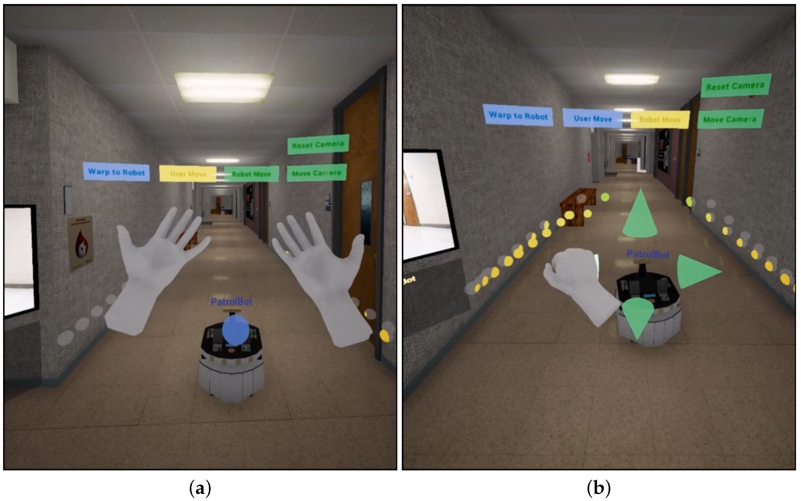
The environment provides context to the robot’s sensor data and allows for operators to interact with the robot in a human/familiar way. The virtual camera is positioned at head height within a world that is accurately sized, scaled, lit, and textured with minimal unrealistic elements. This creates a virtual template of the real environment in which the robot is operating. It should be noted that the depth of information and the sensation of immersion is fundamentally enhanced by utilizing Head Mounted Displays (HMDs), such as the Oculus Rift. Figure 1a shows the operator being immersed into the virtual environment. Observing the environment in which the robot operates as well as the feeling of being side-by-side with the robot provides a significant level of immersion and control.
Regarding control, VETO uses a Leap Motion controller that is mounted to the VR HMD headset. VETO framework attempts to establish the minimal amount of steps between the human intention and resulting robotic or virtual action, a task made complicated by the VR headset. As the user cannot see the real world around them while remotely operating the robot, it can be difficult to use controllers for input without extended practice and hand-eye coordination. With Leap Motion, we can generate an accurate mesh representation of the operator’s hand positions and finger movements in their virtual view, leading to an increased feeling of immersion within the virtual world. These user interfaces are quite intuitive for the operator to utilize. This design achieves the goals of natural interaction and input recognition for the operational aspects of the VETO system. Figure 1b shows the intuitive and natural design of the user interface that allows for efficient and intuitive operation of the robot.
As previously mentioned, there are several challenges towards the goal of producing a game client suitable for robotic tele-operation. A large amount of sensor data must be collected, transported, processed, and presented to the end-user in a way that is intuitive to the operator and accurately reprsents the robot’s real-world state and environment. In addition, the game client will need to generate dynamic levels, including, but not limited to, the walls, floors, ceilings, meshes, and lighting. The game will also need to handle multiple users, much like a traditional multiplayer game, in addition to visualizing the multiple robot agents that exist in the real world. Finally, the ease of expanding the architecture with new robot platforms through the support of their robot interfaces must be considered to minimize the deployment time of new robotic platforms.
The Virtual Environment for Tele-Operation (VETO) architecture, discussed in Section 5 has been developed to meet each of these challenges. Using the Unreal Engine 4 [7] game engine to power its front-end user interface, the VETO architecture seeks to provide an immersive, dynamic, and intuitive virtual reality-enabled environment for the purpose of remote tele-operation. Ideally, a tele-operation system should be portable enough such that the integration of each robot agent can be implemented with minimal time investment. However, robot interfaces can vary greatly in regard to their Application Programming Interfaces (API) and their Operating Systems (OS). Due to these differences, a framework is the ideal architecture for client application on each robot platform. However, in order to provide a framework for robot platforms, a networking system needs to be utilized as a common language between the robot platforms, the centralized HPC server, and the end-user game clients. This common language will need to be cross-platform and supported by a breadth of operating systems. This way, a framework can be utilized by developers to perform tasks that are specific to the robot and its API, such as data queries or performing actions, such as movement. In addition, to maximizing the portability of the tele-operation system, this common language should be easily integrated into new or existing projects. The CrossSock Networking API, discussed in Section 4, introduces the design of a light-weight multi-platform networking architecture to address this issue.
4. The CrossSock Networking API
As discussed earlier, in order to provide a framework for robot platforms, a networking system needs to be utilized as a common language between the robot platforms, the centralized HPC server, and the end-user game clients.
To meet these challenges, the CrossSock networking library was developed and made open to the public [9]. CrossSock was developed based on the Berkeley sockets interface, which is dependent only on system calls. CrossSock supports both the Windows-based WinSock and UNIX-based POSIX libraries and wraps them under a single API, allowing for cross-platform source code. In addition, the CrossSock library is type-safe and object-oriented, which provides a more user-friendly environment for developing network-enabled applications.
CrossSock is a header-only library. As such, it allows for easy integration into any new or existing project. CrossSock also provides several system utilities and high-level packet implementation. Finally, CrossSock provides an event-based client-server architecture to allow easy development of network applications from scratch. The low-level socket classes and the high-level client-server classes are separate. Therefore, developers can include only those CrossSock features that they need for their projects.
The Boost.Asio library, discussed in [22], is a comparable library to CrossSock. Boost.Asio is cross-platform and header-only and supports several of the common network protocols (such as TCP and UDP). In addition, Boost.Asio supports several of CrossSock’s cross-platform system utilities, such as system timers. However, Boost.Asio’s client-server architecture is a lower-level API, and is less portable than CrossSock’s API. CrossSock seeks to address code portability by providing both a low-level socket API and a high-level client-server API, whereas Boost.Asio’s client-server API is designed to only add functionality while remaining low-level. In addition, CrossSock is inherently event-based and includes a high-level packet class, which further increases code portability compared to Boost.Asio.
The Kodo research-oriented network coding library discussed in [23] is also comparable to CrossSock. Although being research-orientated, Kodo is designed to test network architectures and algorithms. As such, it is not a header-only library. In addition, it is not free for commercial use, as CrossSock and Boost.Asio are. The Kodo library is also lower level when compared to CrossSock’s client-server API, which comes at a penalty to code complexity.
The current CrossSock implementation employs simple, adjustable timers to control the rate at which various data is updated to the server and client machines/computers. It does not, however, dynamically adjust these time values based on current network bandwidth usage. CrossSock monitors all connected entities and ensures that they are alive/responsive, allowing for client re-connections within a specific time window. However, when a client is connected and requests or broadcasts data, it is sent in a greedy fashion to the target as soon as possible. In a future version of CrossSock, network bandwidth and latency handling, along with encryption, is planned.
4.1. The CrossSock API
The CrossSock C++ API is designed to be portable and intuitive to use. To this end, the API makes extensive use of the Resource Acquisition Is Initialization (RAII) programming idiom. When coupled with modern C++ smart pointers, RAII allows for the guaranteed closing of sockets, shutdown of servers, disconnect of clients, and de-allocation of packets when they are no longer referenced. In addition, RAII allows for safe exception throwing, and the use of smart pointers allows for safe multi-threading.
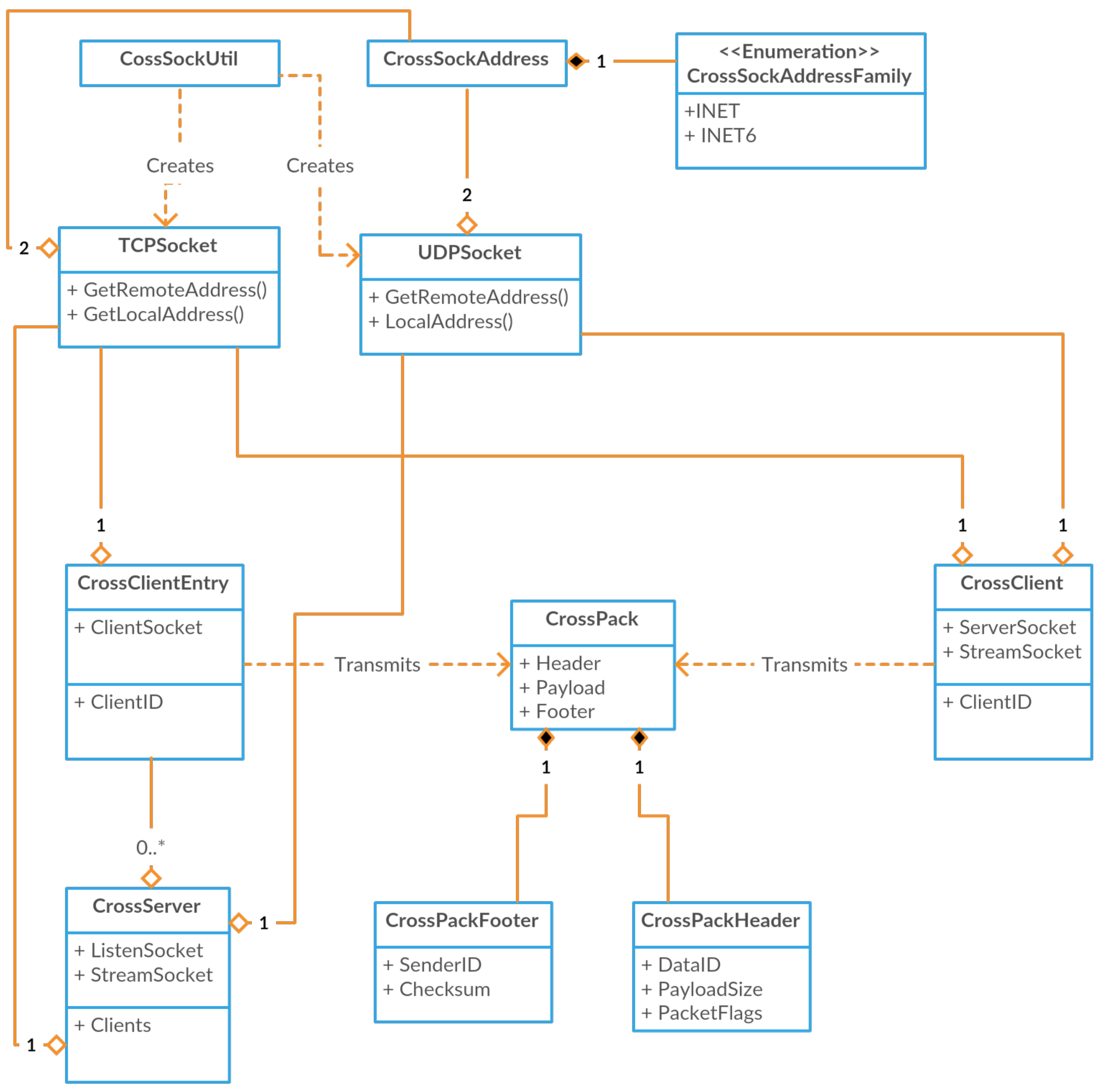
A high-level class view of the CrossSock classes is shown in Figure 2. Although CrossSock allows for safe exception throwing, it internally uses return codes for error handling. This is for efficiency, as CrossSock often throws errors that can be ignored or handled with ease, such as when a socket has already been bound to a port. Most modern implementations of exception handling allow for no overhead during normal use, but suffer from a large performance penalty when an exception is thrown. As such, any exception that could be ignored would suffer a performance penalty. Therefore, CrossSock uses simple return codes for its internal error handling, while allowing any application that uses CrossSock to throw exceptions safely to satisfy its own error handling needs.
4.1.1. The Socket Interface
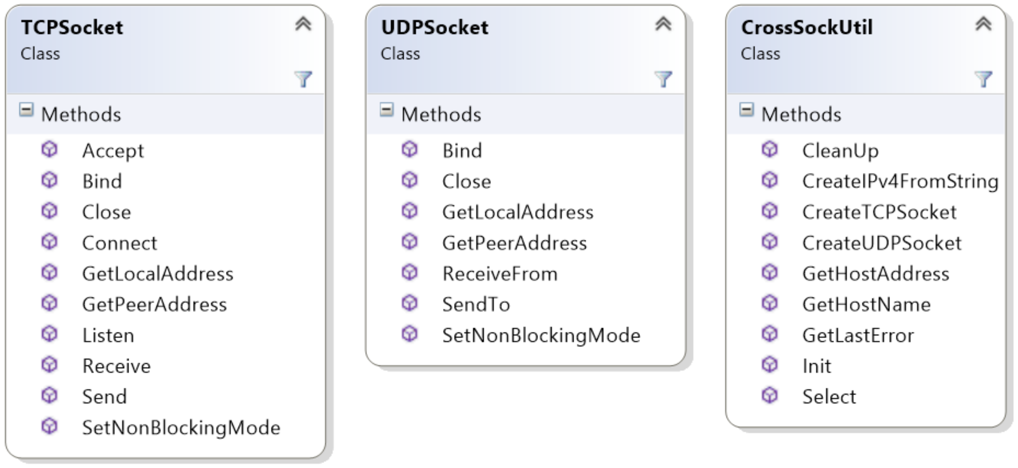
The socket API is composed of the Transmission Control Protocol (TCP) and User Datagram Protocol (UDP) socket classes, which have been implemented to provide ease of use when compared to traditional system sockets. Both of these socket classes are object-oriented, support both blocking and non-blocking modes, and hide the primitive and type-unsafe system sockets from the developer. Static utility functions are available in the CrossSockUtil class, such as the commonly used select function, cross-platform error handling, as well as namespace resolution functionality and other tasks related to addressing. In addition, both socket types must be constructed through the constructor functions in the CrossSockUtil class. Note that all classes and types in the CrossSock library are within the CrossSock namespace to avoid naming conflicts with other libraries. The entire socket API is provided in CrossSock.h, i.e., it is a header-only API.
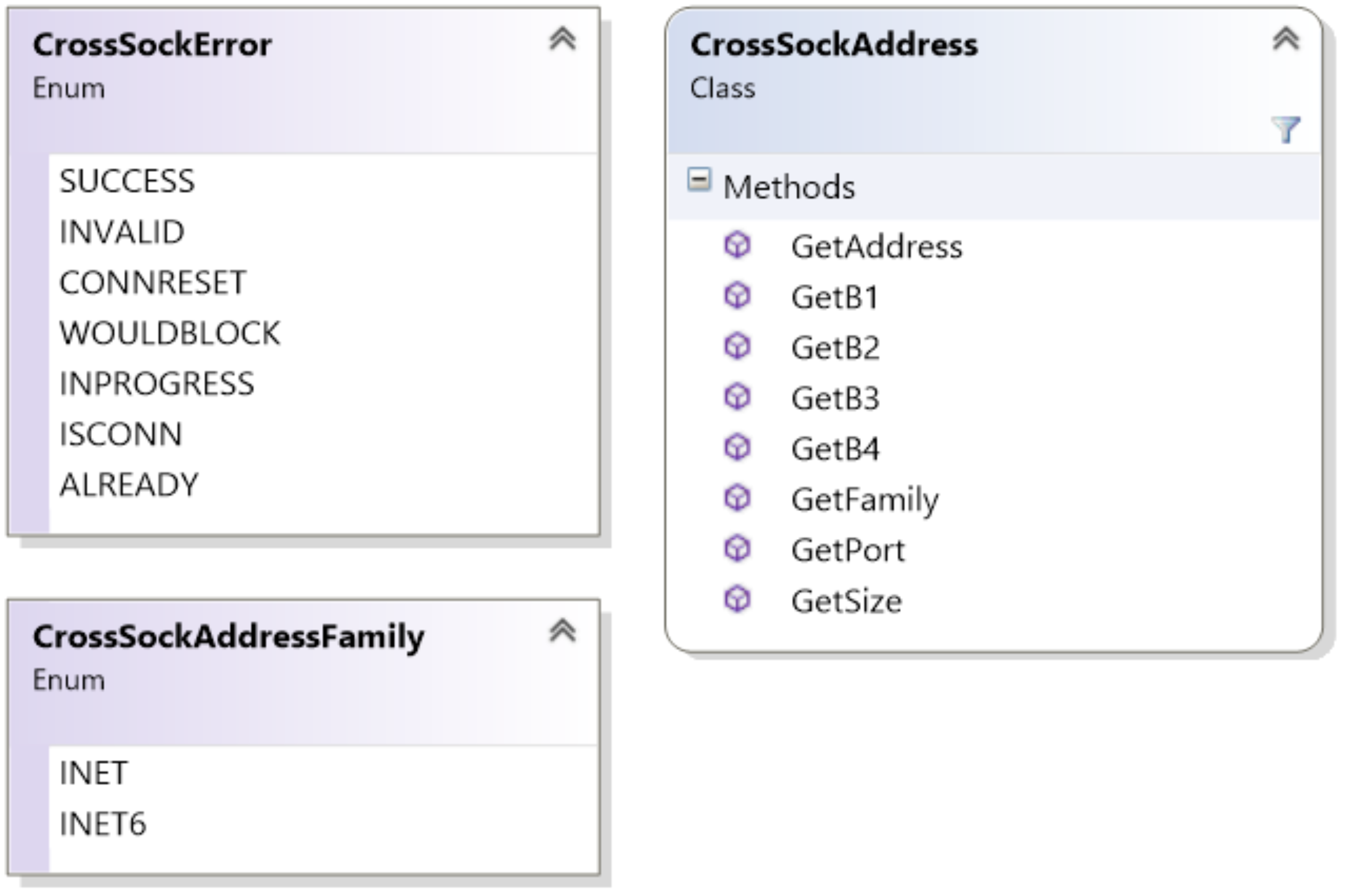
Addressing in CrossSock is handled through the CrossSockAddress class. This class handles both IPv4 and IPv6 addresses, and makes it easy to provide addresses for both the Socket API and the Client-Server API. Addresses can be specified through a port and 4-byte address, or through a port and 4-tuple address. Addresses can also be created with the CrossSockUtil class with a string. Some of the important addressing functionality is shown in Figure 3.
UDP sockets involve simple data transmission from one address to another. UDP has a small overhead, and thus, is useful when bandwidth and latency need to be optimized. However, this is a result of the protocol being connectionless and unreliable. Overall, UDP is well suited for streaming and multimedia applications. UDP sockets must be bound to an address with its Bind function, which specifies the port and address of the socket. Then, the socket can send data to a given address, receive data being sent to the bound address, or close the socket through the available functions. The UDP socket class is shown in Figure 4.
Error codes are used instead of run-time errors or other blocking-type returns. It is up to the function callers to deal with the resulting error codes and decide whether network execution should be halted. Most error codes are handled by a CrossSock-defined, “CrossEvent” callback that is established and expanded on by the owning class. CrossEvents provide extra information about error codes, along with packet data (should it be available). Unless specified, the network will handle the error code and continue to run for as long as possible, unless the owner chooses otherwise in their defined handler events.
Error handling occurs by reading the last error with the CrossSockUtil class, which returns a CrossSockError enumerator. Socket functions often return an error as well, although they are usually limited to generic success or failure, and rely on the GetLastError function to receive the specific error that has occurred. Note that some errors, such as ISCONN and ALREADY, are not critical errors, and the application can still proceed as normal. In addition, the WOULDBLOCK error is given for non-blocking sockets that need more time to finish a task. Generally, it is good practice to check for the CONNRESET error after each receive call, as this error is caused either due to a critical network failure or when the connection has been closed on either side. The full list of errors is shown in Figure 3.
TCP sockets are useful when data needs to be sent reliably. As such, they are connection-based and require additional functionality when compared to UDP sockets. Similar to UDP sockets, they must first be bound to a given address and port. Then, they must execute the listen function, which handles any connection attempts to the bound address. Likewise, the connecting socket must execute the connect function to connect to a specific address. This returns a new TCP socket which represents the specific connection from one address to another. This new socket can send and receive data, as well as execute the close function to end the connection. The TCP socket class is shown in Figure 4.
Finally, the CrossSockUtil class includes the static Init and CleanUp functions. These functions act as mandatory static initialization and de-initialization of the CrossSock library due to the WinSock dependency and its mandatory initialization and de-initialization. As such, these functions are mandatory for both the low-level socket API and high-level client-server API, and should only be called once. The Init function should be called before any CrossSock sockets, clients, or servers objects are created, and the CleanUp function should be called after all objects have been destroyed and are no longer necessary.
4.1.2. System Utility and Packets
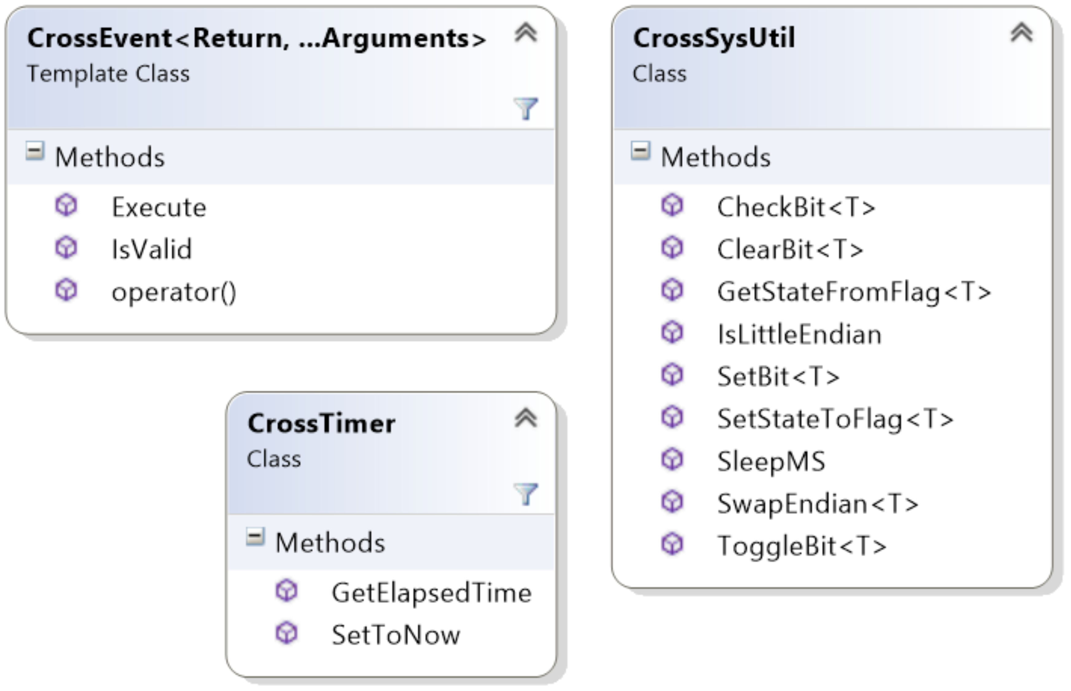
There are several system tasks that need to be made available for the implementation of a high-level client-server architecture. Many of these system tasks, such as bit-wise operations and endian utility functions are provided in the CrossSysUtil class. In addition, a millisecond-resolution cross-platform sleep function is provided, as well as a simple cross-platform timer class. All system utilities are available in CrossUtil.h and some important functionality is shown in Figure 5.
Simple function delegation is provided through the CrossEvent abstract class. A single global function can be delegated through the CrossSingleEvent class, and an object function can be delegated through the CrossObjectEvent class. The CrossDataEvent class represents the CrossSock data event implementation, which can include an array of CrossEvent delegates and supports both CrossSingleEvents and CrossObjectEvents. Data events also include a human-friendly name and a network-optimized data ID for use by the high-level packet and client-server APIs.
In addition, a high-level packet class is necessary so that developers can easily serialize complex data and classes to be sent or replicated over the network. To meet these needs, the CrossPack class is available in CrossPack.h, and some common functions are shown in Figure 6. Each packet is composed of a header, a payload, and an optional footer. The header includes the data ID of this packet’s payload data, any packet flags, such as what data is included in the footer, as well as the payload’s size. When data is received through a socket, a packet header can be created to define the data through the static PeakHeader function.
The payload of the packet represents the actual data received or sent. Data can be added to the payload through the add functions, including a generic type, an array of bytes, or a string. The packet can be serialized, which occurs only once unless the packet is altered. Afterwards, this packet can be sent as an array of bytes through a TCP or UDP socket. Once received, a packet header can be peaked from the data, which contains the data ID and payload size. Data can be removed like a stack from the payload through the remove functions, which are similar in functionality to the add functions. The packet can be reset, which will return the read index to the front of the payload stack. In addition, the packet can be cleared, removing all data from the payload. Payloads are lockets to 1486 bytes, which, in combination with the header and footer, result in a 1500 byte max size for the packets. This allows packets to be sent quickly and efficiently across various network configurations. Note that data types are automatically converted to little endian when added to the payload, and are converted back to the native machine’s endianness when removed from the payload. In addition, some constructors delete the internal payload buffer when the destructor is called, and thus, references should be utilized for packet objects when possible.
Finally, a footer can be added to the end of the data through the finalize function, and can be retrieved from data through the PeakFooter function. This footer can include an optional checksum and sender ID. The checksum is useful to check if data has been altered during network transfer, and is not necessary with TCP sockets. The sender ID can be set by the sender such that the receiver can match a packet with a known sender. Unlike serialization, once a packet has been finalized, it can no longer be altered. However, data can still be removed from the packet, as this does not affect the payload but rather, advances the read index.
4.1.3. Client–Server Architecture
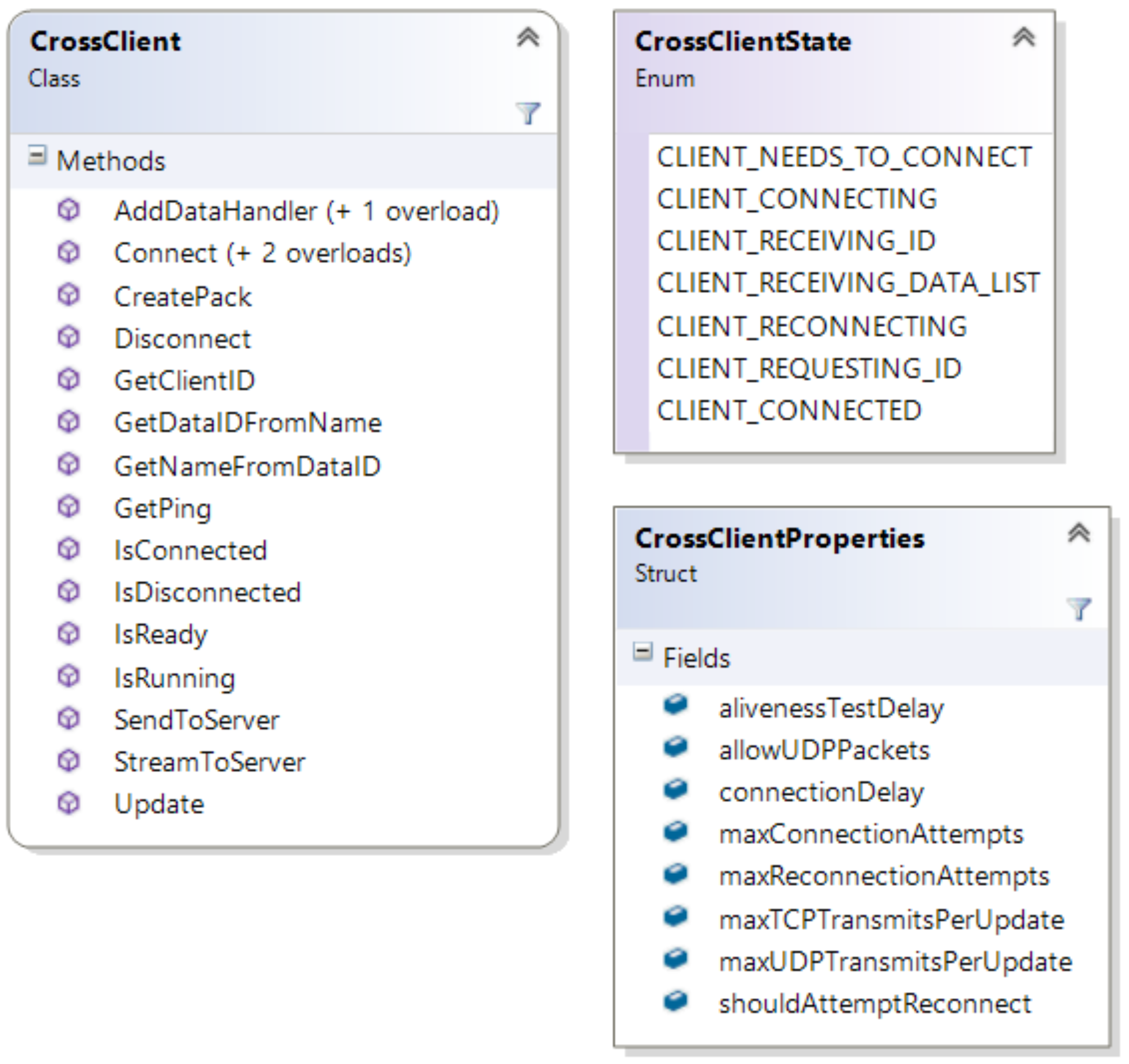
Through the utilization of all of the sockets, system utility, and packet classes, CrossSock also provides a high-level client–server architecture through the CrossClient and CrossServer classes. Servers are always running and provide data and services to connecting clients. Although a single client object can only connect to one server at a time, there is no limit to the number of client objects that an application can create. CrossClients and CrossServers both utilize non-blocking sockets and can send and receive data through TCP using the send terminology, and through UDP using the stream terminology. In addition, both clients and servers are event-based, and primary functionality is provided through adding custom data handlers to the client and server objects. These handlers are provided with the incoming packet which contains the matching data type. This incoming packet can then be used to read the incoming data based on the event, and additional data can be sent as needed. Both classes also include several connection-based events, such as when clients are connected, disconnected, or reconnected, which can be set on all client and server objects. Due to being non-blocking and designed to be easily integrated into existing architectures, it is necessary to call the Update function on all client and server objects to provide the connection, sending, and receiving functionalities. Note that clients and servers should never be destroyed, and instead, a reference to each object should be used until the end of the application. Both servers and clients can be configured through their respective property structures. CrossClients are available through CrossClient.h and are outlined in Figure 7, and CrossServers are available through CrossServer.h and are outlined in Figure 8.
Servers have a similar API to clients, with one important difference. Server must maintain a list of known clients, which are represented by the CrossClientEntry class. Client entries are not CrossClients, but rather, a simple object composed of all the necessary information for each client. The client entry is provided with each data event, such that the event can read information about the client and send additional data back to that client. In addition, clients can be manually disconnected from the server through their client entry. Client entries contain a general reference to user data, which can allow for developers to provide them with a reference to an object of custom data for each client. The developer is given complete control and responsibility of this data, including its creation and deletion. The client entry, including its custom data, is saved on client disconnect until a given timeout period expires, which is defined in the server’s configuration. In this way, data is removed for clients that have disconnected intentionally, but custom data can be recovered for clients that reconnect to the server within the timeout period.
All data types and objects in the CrossSock library are hashable. The client and server both utilize hash tables for linear operations on their list of data events. In addition, the server utilizes hash tables for its blacklist, whitelist, and list of client entries.
One important consideration when sending data between CrossClients and CrossServers is the CreatePack utility function, which efficiently creates a packet based on a given data name. This data name is converted to the correct data ID and assigned to a new packet. A reference to this new packet is returned for the developers’ use. However, it is important to delete this reference manually after it has been sent or streamed to ensure there are no memory leaks in the application.
The CrossSock connection process starts with a server calling the Start function, which binds a socket to a given address and port. The server automatically listens for potential client connections on Update and accepts new client connections with its update function based on its configuration, blacklist, and whitelist. Likewise, the client begins its connection process through calling the Connect function. Next, the server sends an initial handshake packet to the client, which, in turn, sends either a request for a new client ID or the continued use of its old client ID if reconnecting. The server responds with the new ID, or existing ID, if requested and still available on the server. Then, the client resets all of its data IDs and requests the list of all known data IDs from the server. Once all of the data IDs have been received, the client sends a final handshake packet, letting the server know that it is ready to transmit data. An outline of the CrossSock connection process is shown in Figure 9.
5. The VETO Architecture
As discussed in Section 1, there are many benefits and challenges to the goal of a game client for the purpose of robotic tele-operation. Real-world data must be provided to the game client within bandwidth limitations and with minimal latency, and all environmental data must be processed such that the virtual environment visualization is minimalistic, clean, and optimized. Moreover, all real-world sensor data, user input, and resulting robot commands must be generalized such that they can be applied to various different robot platforms, each employing unique actuators and sensors.
The Virtual Environment for Tele-Operation (VETO) architecture was designed to meet each of these challenges. The VETO architecture is a tele-operation system that works closely with the CrossSock library and Unreal Engine 4 (UE4) game engine to provide a feature-rich framework for developers. This framework can be employed to implement robotic agents into an immersive and VR-enabled end-user game interface. Game levels are generated dynamically on a GPU-accelerated server based on real-world sensor data from the robotic agents. This data is then broadcast to all end-user game clients to provide users with a virtual environment that closely represents the real-world robot environment. This environment is used to interact with the robotic platform and its environment in a natural and intuitive fashion.
This section discusses the VETO architecture in detail. The system’s design, functionality, and limitations are all explored, and qualitative results are provided below.
5.1. Methodology and Approach
The proposed architecture is split into three major network components. First, the VETO High-Powered Computing (HPC) server provides GPU-enabled services, such as visual odometry tasks and 3D map creation, to the end-user clients and robotic agents. The HPC server is extendable, which allows developers to implement additional services. The HPC server supports multiple end-user game clients and multiple robotic agents.
Next, robotic agents are included in the architecture through the Robot Operating By ITself (ROBIT) client framework. To utilize this framework, the ROBIT clients must be implemented for each robot that employs a unique robotic interface. The framework exposes functions that allows each ROBIT client to complete critical tasks, such as querying for real-world environment data from the robot or to execute robot commands, such as movement.
Finally, an end-user game client is provided via Unreal Engine 4 (UE4), which may include multiple ROBIT actors. All processed data is provided to developers inside UE4’s blueprint visual scripting system, which allows for easy visualization and integration of new robot agents into the end-user game interface. Basic sensor visualization is also provided, but can be customized for each ROBIT actor. The game interface also provides an intuitive and generalized control interface, which allows end-users to control the robot client in a unified fashion, despite any hardware or software differences between robot platforms.
Several pieces of robotics equipment, including the PatrolBot and PeopleBot robot platforms provided by MobileRobots are currently implemented in the VETO architecture. Each of these robots employs the Advanced Robot Interface for Applications (ARIA) robot interface, and as such, both of these platforms share a single ROBIT client. The differences in sensor mount location and quantity can be defined in each robot’s VETO configuration file provided by the ROBIT framework, including configurations for the Laser Range Finder (LRF), Bumblebee stereo camera, and sonar.
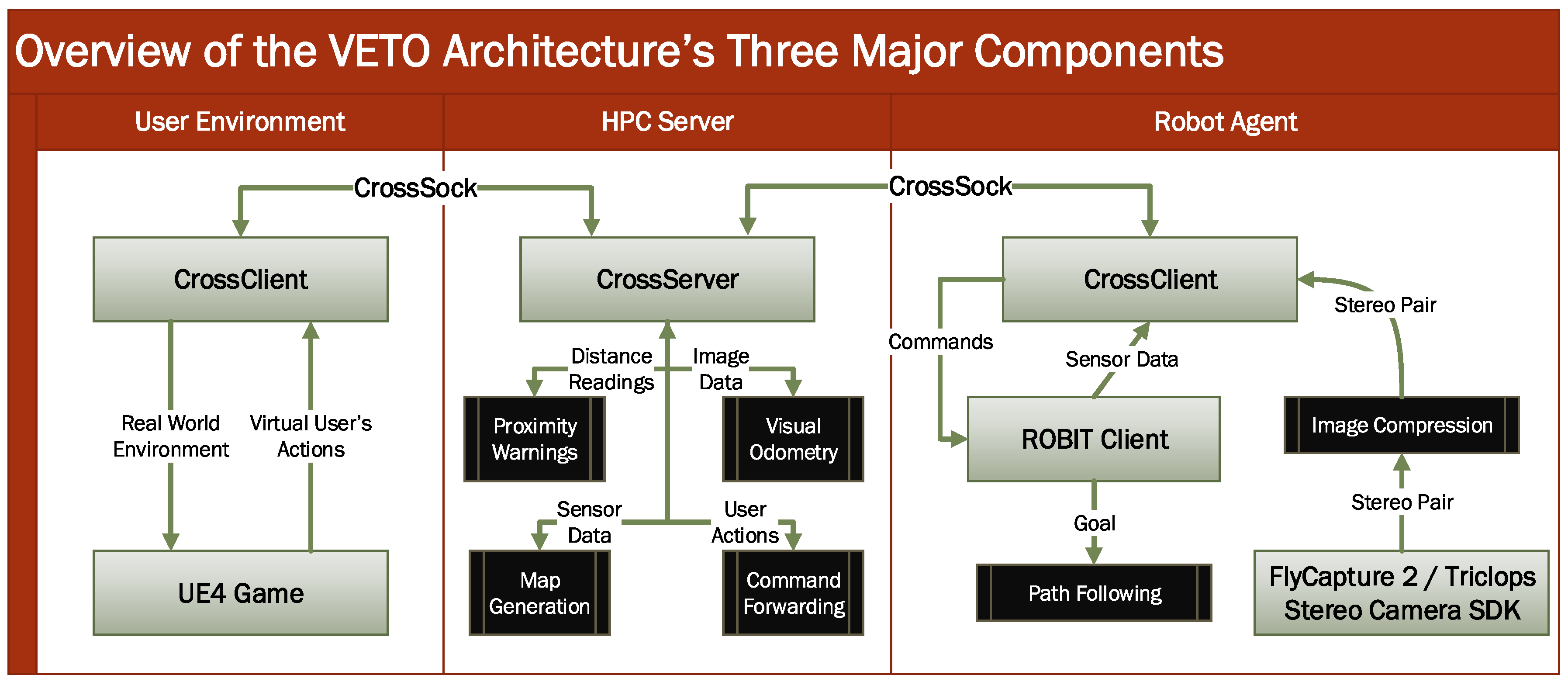
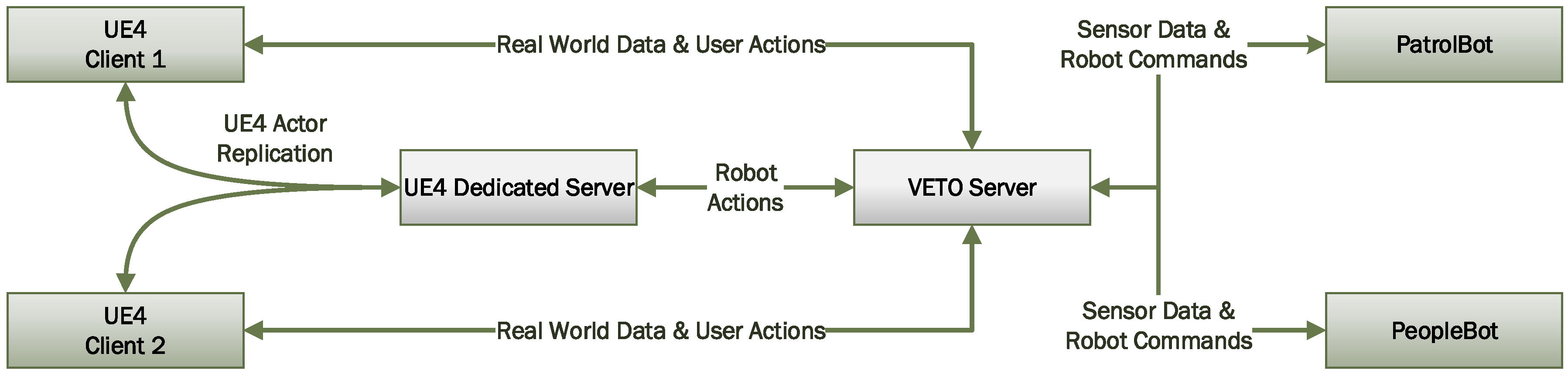
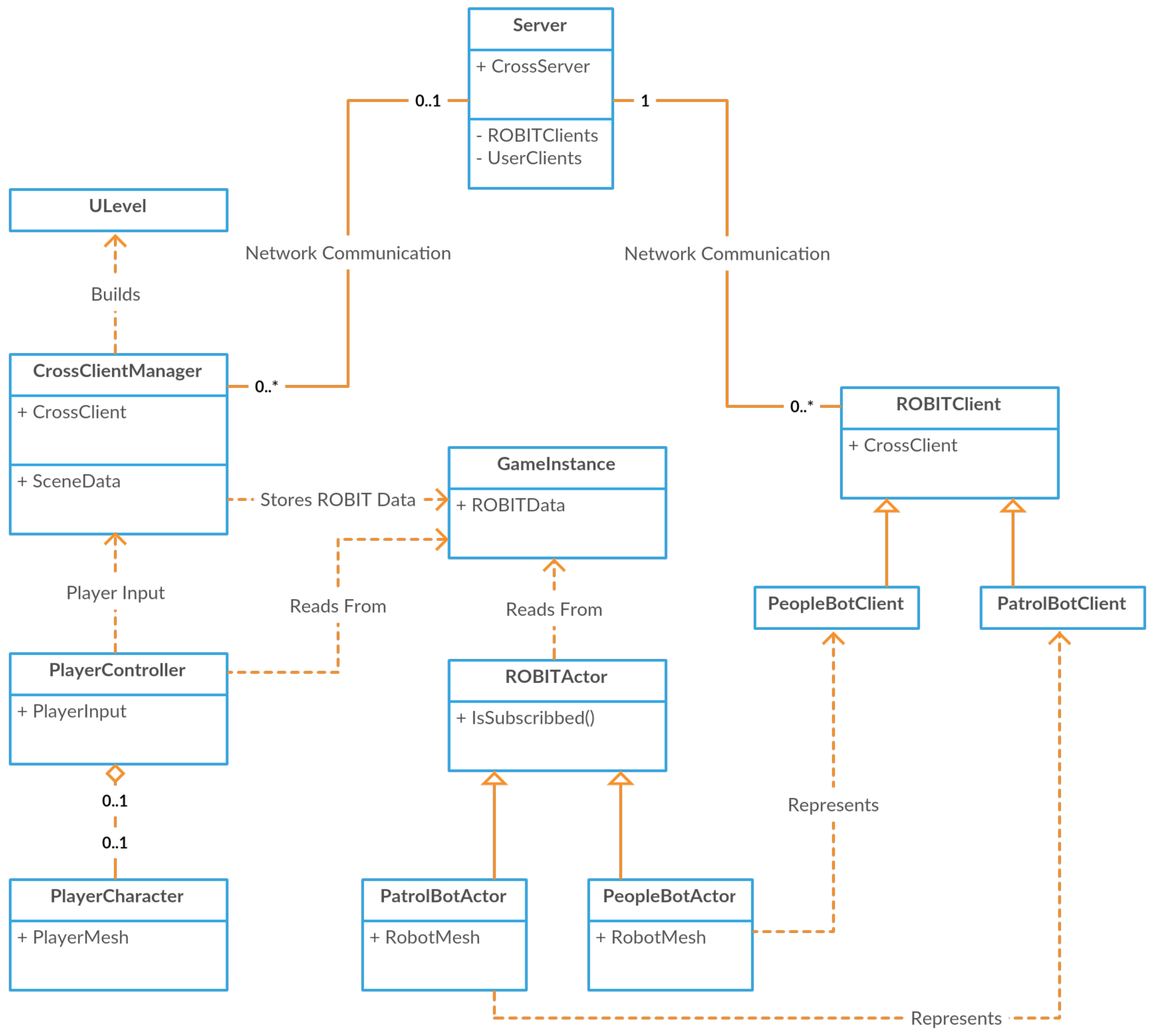
An overview of tasks handled by each of the components in the VETO architecture is shown in Figure 10. In addition, an overview of all network communications in the architecture is shown in Figure 11. Finally, a high-level class view of the VETO classes is shown in Figure 12. The three VETO components are detailed below.
5.1.1. HPC Server
The HPC server exists for two major reasons: to optimize network traffic through a client–server architecture and to offload computationally expensive tasks from the robot clients. A client–server architecture minimizes the network load by reducing the total connections on a given network. Raw sensor data is sent to the robot and processed in a single location. This data can be passed along to each end-user, which broadcasts only the necessary information to build the dynamic game level.
The HPC server handles several critical tasks. First, the HPC server provides end-users with the list of connected ROBIT clients, allowing each end-user client to subscribe to any number of given ROBIT clients. This subscription system allows each end-user to communicate indirectly with a ROBIT client by forwarding any commands received by the server to any of the end-user’s subscribed ROBIT clients. This subscription system works in reverse as well; any sensor data received by the HPC server from a ROBIT client is automatically forwarded to all subscribed end-user clients.
Moreover, there are multiple subscription levels provided by the VETO architecture, each providing a different level of environment data to a subscribed end-user client. Therefore, the UE4 dedicated server can remain partially subscribed to all ROBIT clients for the purpose of UE4 actor replication. This way, critical data such as the ROBIT position and orientation can be replicated to all clients without the need to subscribe to each of the ROBIT clients.
Next, the HPC server processes sensor data to provide each end-user with high-level environment data, such as the location of walls and the orientation and status of objects. This environment data is constructed based on all available sensor data from all connected ROBIT clients.
Finally, the server processes all of the general distance readings provided by each ROBIT client. Distance readings account for all of the LRF and sonar data on the robotic platforms. The distance readings that are within a preset threshold are broadcast as proximity warnings to the UE4 dedicated server and visualized as replicated actors. This provides all proximity warnings in the scene to all end-user clients with minimal network load. In addition, the entire list of distance readings is forwarded to fully subscribed end-user clients, such that all LRF and sonar data can be visualized on the ROBIT that is in focus. While proximity readings contain only an end point, distance readings are composed of a start point, start orientation, and a distance value. This distinction is designed to minimize the network load, while providing the option for improved distance reading visualization on subscribed users’ game clients.
The use of a centralized server does raise the question of network latency, as commands must be forwarded from the server to each relevant robot client. However, when considering network scalability, an ad-hoc network becomes less ideal, as more network resources are necessary as additional end-user clients are included in the system. For extreme cases such as planetary exploration, a centralized server is the only viable option. As such, a direct connection from end-users to ROBIT clients is omitted in the VETO architecture due to scalability concerns and to maintain a generalized tele-operation system.
5.1.2. ROBIT Client Framework
ROBIT clients are ultimately designed to be fully autonomous agents. The ROBIT client framework hides all of the common network communications and tasks between robot agents and the HPC server, allowing developers to focus only on the integration of the robot interface. Sensor tasks necessary for the integration of robot interfaces include the following query operations:
- LRF data, Sonar data, and any other distance readings available on the platform.
- Image data, including stereo pairs.
- Any physical bumpers and their current states.
- The transform function from the platform’s internal coordinate system to UE4’s coordinate system, which is the standard for the VETO architecture.
- The estimate of remaining battery life, if relevant.
- Login data, such as the robots friendly name and type ID used by the end-user for visualization.
- The robot’s physical location and orientation, if any localization is employed on the platform.
- The facing of the platform, which can be decoupled from the robot’s actual orientation, such as with pan-tilt cameras.
In addition, actuator tasks necessary for the integration of robot interfaces include the following commands:
- Moving the platform, given a 3D direction vector and a normalized speed.
- Panning or tilting any cameras, given the degrees to rotate.
- Playing an audio queue, if relevant.
A custom configuration file can be defined for each ROBIT client. This allows developers to define minor differences, such as the minimum/maximum motor speed or sensor configurations, between any robot platforms that utilize the same robot interface. This further increases the portability of the VETO architecture, as developers do not need to waste time developing similar ROBIT clients for similar robot platforms, such as with the PatrolBot and PeopleBot.
5.1.3. End-User Game Interface
The VEOT’s end-user game interface was developed much like a traditional game, and has been termed Unreal Robotics. The primary components of the game interface are the Cross Client Manager (CCM), which includes the CrossClient that communicates with the HPC server, as well as the Unreal Robotics Game Instance (URGI), which stores real-world environment data for use by the player actors, ROBIT actors, and any other objects that need access to the real world data.
VETO was designed in line with traditional video game development and implements movement collision, lighting propagation, physics constraints, particles, and screen rendering via UE4’s built-in components. However, we implemented several custom modifications, including the CrossClient Manager (CCM and the Unreal Robotics Game instance (URGI). The CCM handles incoming and outgoing network communication between the client and HPC server. The URGI stores any persistent information about real-world or virtual-only actors that needs to survive between simulations and be accessible during runtime to any ROBIT actors, player actors, or utility functions.
All of the URGI data is blueprintable, which allows for modification of the project with either C++ source code or blueprint scripting. As such, additional robot agents can be added to Unreal Robotics through simple scripting and the addition of art assets. Furthermore, simple sensor visualization is provided by default for each ROBIT actor, and can be overridden with custom logic. This allows developers to rapidly add new ROBIT actors to the project, while still allowing for custom logic when necessary.
The entire virtual world is created at run-time using the game instance information alongside robot sensory information to generate the most up-to-date environment possible. A connected robot scans the environment around it and provides a map that is transmitted to our server, parsed, and then broadcast to all connected clients. VETO automatically pulls from a pool of environmental objects and textures that we created in-house to generate walls, floors, ceilings, objects, and lighting as needed. The robot localizes itself within its own scanned map and determines its position and broadcasts this information to the server. A 1:1 virtual representation of the world is used within the VETO architecture for the placement of the 3D robot mesh in this established position to keep the robot accurately placed within the environment. The entire environment is accessible and modifiable at run-time by ROBITs and by players.
Base classes were created for ROBIT actors and their sensor components. As a result, other robot models brought into the VETO framework will load and display properly, though it is recommended to also add a custom mesh asset that matches that robot’s physical appearance. As all VETO-enabled robots use a configuration file that requires a model identifier, any connecting robots of the same model/type will automatically use the same virtual configuration, even if they have never connected before.
To ensure the proposed architecture is a valuable utility for real-world applications, the design of the VETO allows for dynamic reconfiguration of the environment through the use of an In-Game Editor. This IGE allows the operator to manipulate objects within the scene in real-time while the game is in play. Figure 13 demonstrates the In-Game Editor (IGE) functionality, in which a bench is placed in the middle of the hallway.
In the current implementation of the system, textual feedback is used for input lag and loss of connection, showing the user a log of any warnings or events that require attention. In the future, we plan on providing additional telemetry to the user.
6. Experimental Results
This section will first present a number of applications in which the proposed VETO architecture helps to improve the situational awareness and interactions required between the robot and its human operator. The section will then present the set-up of two experiments in a human usability study and demonstrate performance improvements achieved by utilizing the proposed environment compared to regular operations of robotics agents.
6.1. Qualitative Results
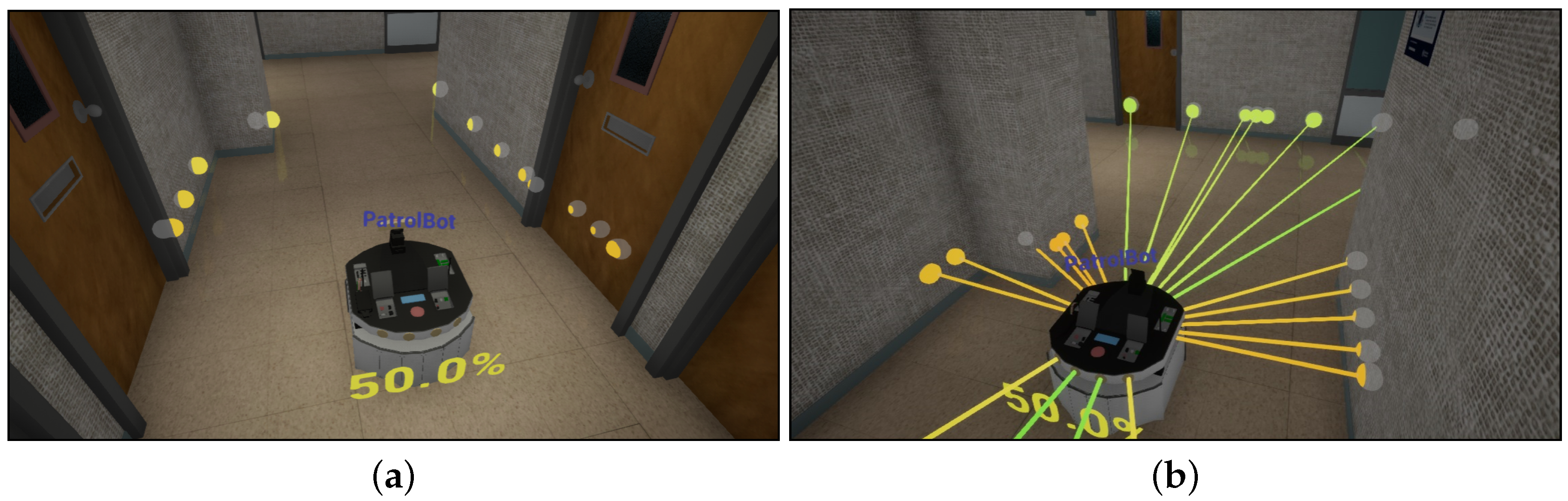
Qualitative results of the VETO architecture in action were gathered, starting with normal usage in an office hallway shown in Figure 14a. In this figure, the PatrolBot is being driven manually down a hall. The environment is known and is visualized around the robot. The spheres displayed in the virtual environment represent the real-world readings from the robot in real-time from its LRF and sonar sensors. In addition to the environmental data, the current ’throttle’ (normalized speed) of the robot is displayed behind it as a percentage. The robot’s name is shown hovering above its current location.
Figure 14b shows the optional distance sensor (LRF and sonar) visualizations as a raycast in the virtual environment from the robot to its final location. This visualization can be enabled on the current robot whenever the proximity warnings are not enough for manual piloting.
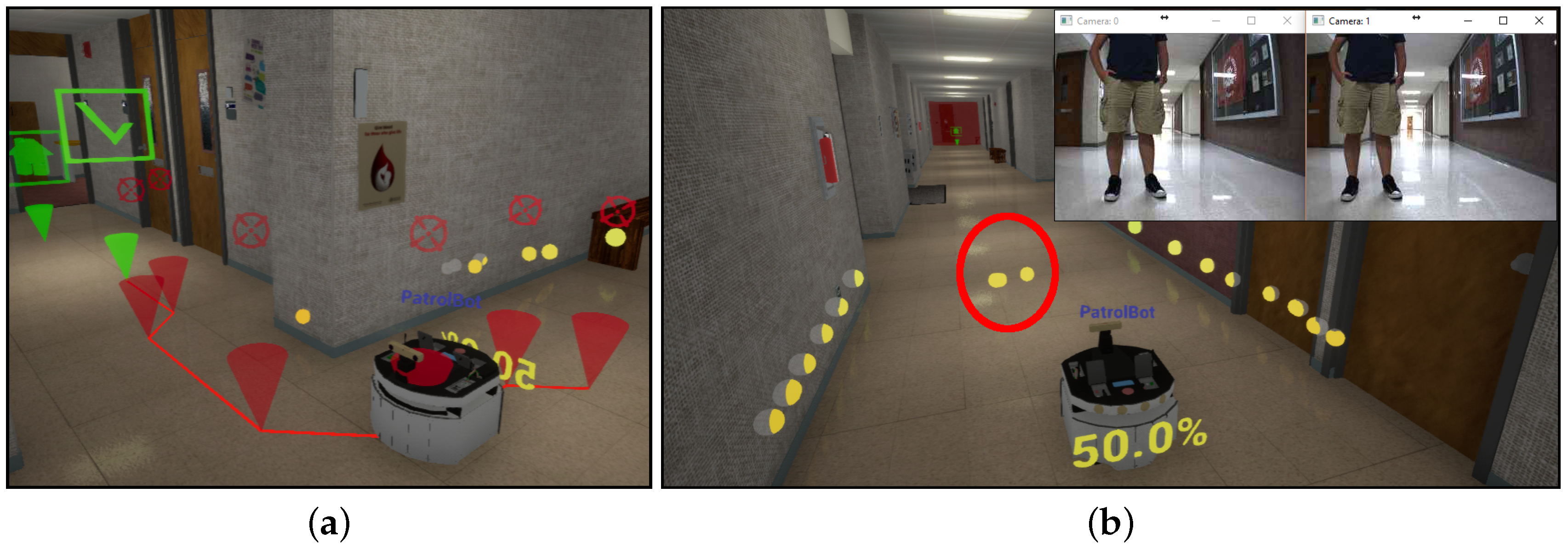
Next, Figure 15a demonstrates the architecture’s ability to automatically path the robot from its original location to any reachable location in the mapped environment. In this figure, the red waypoints show the path’s segments, and the final green waypoints represents the robot’s goal.
Obstacle visualization is shown in Figure 15b. The circled section is an unknown obstacle that is not reflected in the map data which is visible on the stereo camera. In the current implementation of the VETO architecture, this type of unknown obstacle is visualized as free-floating proximity warnings. If an obstacle is of known origin (e.g., a bench or other type of encountered object), the mesh for the object is placed within the environment.
In certain applications, the environmental conditions are outside of the operators’ control. Moreover, there may be scenarios in which part, or all, of a sensory system may fail whilst the robot and its operator are performing a task. One such scenario is the sudden loss of visual condition or camera input. The VETO architecture has significant benefits over traditional control mechanisms in such situations, as shown in Figure 16. Here, the robot is navigating a maze in the real-world environment. During this operation, the lights are on, but are suddenly turned off is shown. In traditional applications, the loss of sensory data would amount to the entire operation’s failure. However, since this environmental condition does not alter the structure of environment, the human operator takes control of the robot’s operation within the virtual environment to bring the task to completion.
6.2. Human Performance and Usability Study
To validate the benefits and usability of the VETO architecture, a human usability study wais designed, in which human subjects were asked to perform two structured tasks remotely via a robotic agent, as described below.
- The Navigation Task: In the first task, called Navigation, the subject was asked to navigate a robot through a maze. There were several physical and non-physical hazard zones populating the maze. The subjects were given 20 min to complete the navigation. The time taken to completely navigate the maze as well as the number of physical and non-physical (hazard zone) hits were recorded for each subject.
- The Exploration Task: In the second task, called Exploration, the subject was asked to explore the office corridors to find three symbols placed randomly within the environment. Again, the subject, was given 20 min to find all three symbols. The time to complete the task as well as the number of symbols found by the subject were recorded.
In order to validate the performance achievements and compare the proposed architecture with traditional tele-operation techniques and user interfaces, each subject participated in two sessions, spaced approximately 30 days apart. In order to counterbalance the experiment, participants were randomized, such that half were assigned the VR session first while the rest were assigned the ROV session first.
- Regular (ROV) Session: The subject sat at a computer desk and performed the tasks using a keyboard, mouse, and/or joystick, and watched the results via the video feed from the robot camera(s). There was a radar-like Head-Up Display (HUD) to show the location of the robot within the environment. Figure 17a shows the view as seen by one of the test subjects while performing the navigation task.
- Virtual Reality (VR) Session: The subject sat at a computer desk and performed the tasks in the proposed virtual reality environment. The subject communicated the actions to the robot via the proposed virtual reality interfaces and watched the resulting operation on a Head Mounted Display (HMD). The VR view as seen by a subject performing an exploration task is shown in Figure 17b.
6.2.1. Participants
Currently, 25 subjects have completed both the ROV and the VR sessions. Participants included students, staff, and faculty at the University of Houston—Victoria. Forty-four percent of the participants were female and 56% were male. Thirty-six percent of participants were younger than 24 years, 40% were between 25 and 34, and 24% were older than 35 years. The study participants were quite diverse, including African American (12%), Asian (24%), Hispanic (32%), and White (24%) ethnic groups. About 8% of the participants did not declare their ethnicity. The highest degrees earned by participants were high school (28%), associate (16%), bachelor’s (28%), master’s (8%), and doctoral (20%).
6.2.2. Descriptive Statistics
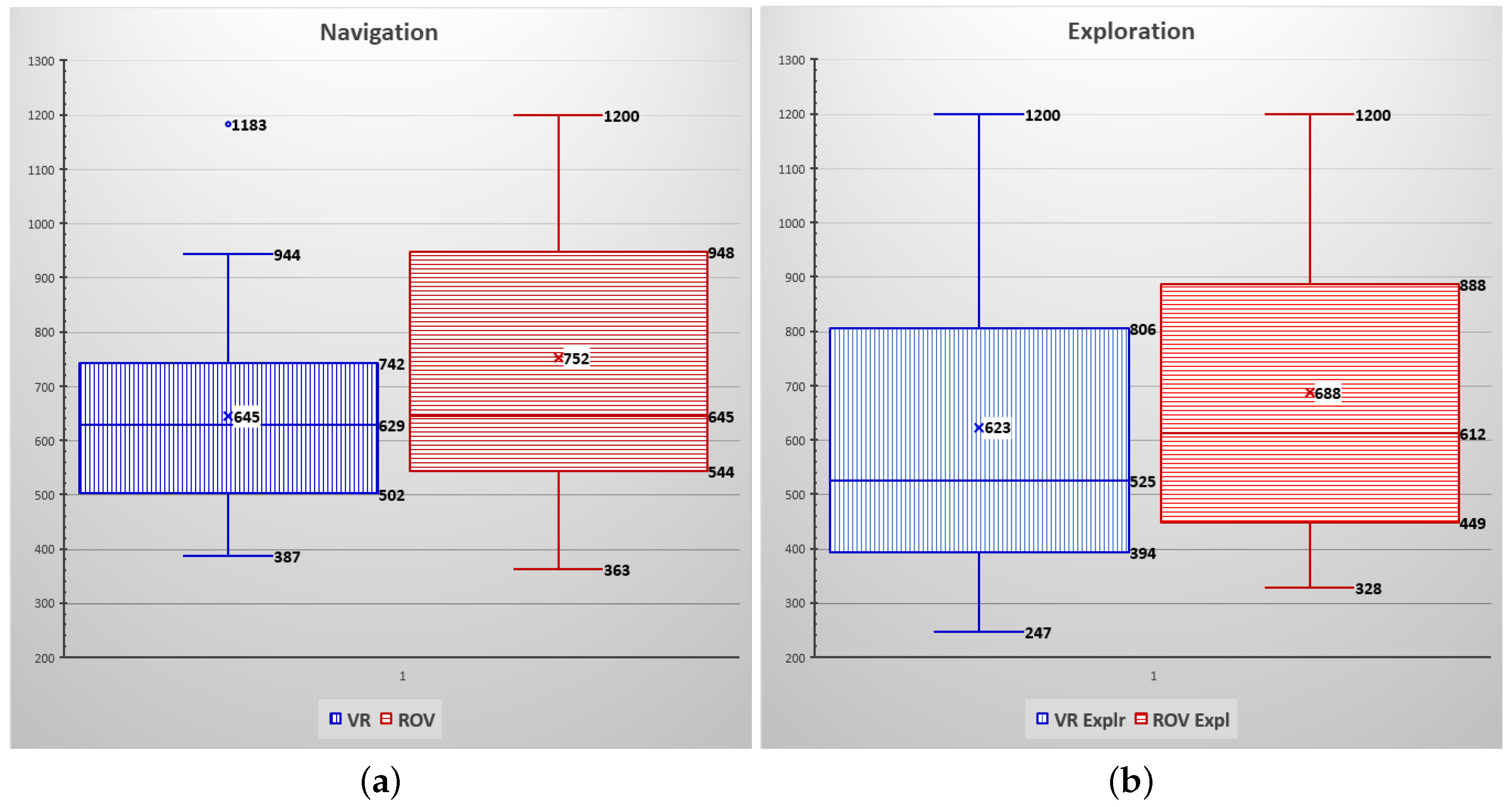
Figure 18 shows the descriptive statistics results for the completion time to perform the Navigation (Figure 18a) and Exploration (Figure 18b) tasks during the VR and ROV sessions. In each figure, the vertical axis shows the task completion time in seconds.
Completion Time: The mean completion time for the Navigation task in the VR session was 645 s (median of 626 s), compared to the mean completion time of 752 s (median of 645 s) for the ROV session, as seen in Figure 18a. In other words, participants took, on average, 1 min and 47 s longer to navigate the maze in the ROV session than in VR session. Also, from Figure 18a, it can be observed that while the fastest completion time in the ROV session (363 s) was 24 s faster than the VR session (387 s), all participants in the VR session completed the task, while at least one participant did not finish the ROV session within the 20 min (1200 s) time limit.
Figure 18b shows the completion time for the Exploration task. The mean completion time for the VR session was 623 s (median of 525) while the ROV session took, on average, 688 s (median of 612) to complete. In other words, participants completed the VR session, on average, 65 s faster than the ROV session. The fastest participant completed the exploration task in a little over 4 min, compared to 5 min and 28 s for the fastest ROV completed time. Note that in both sessions, at least one participant was not able to find all three symbols within the alloted 20 min.
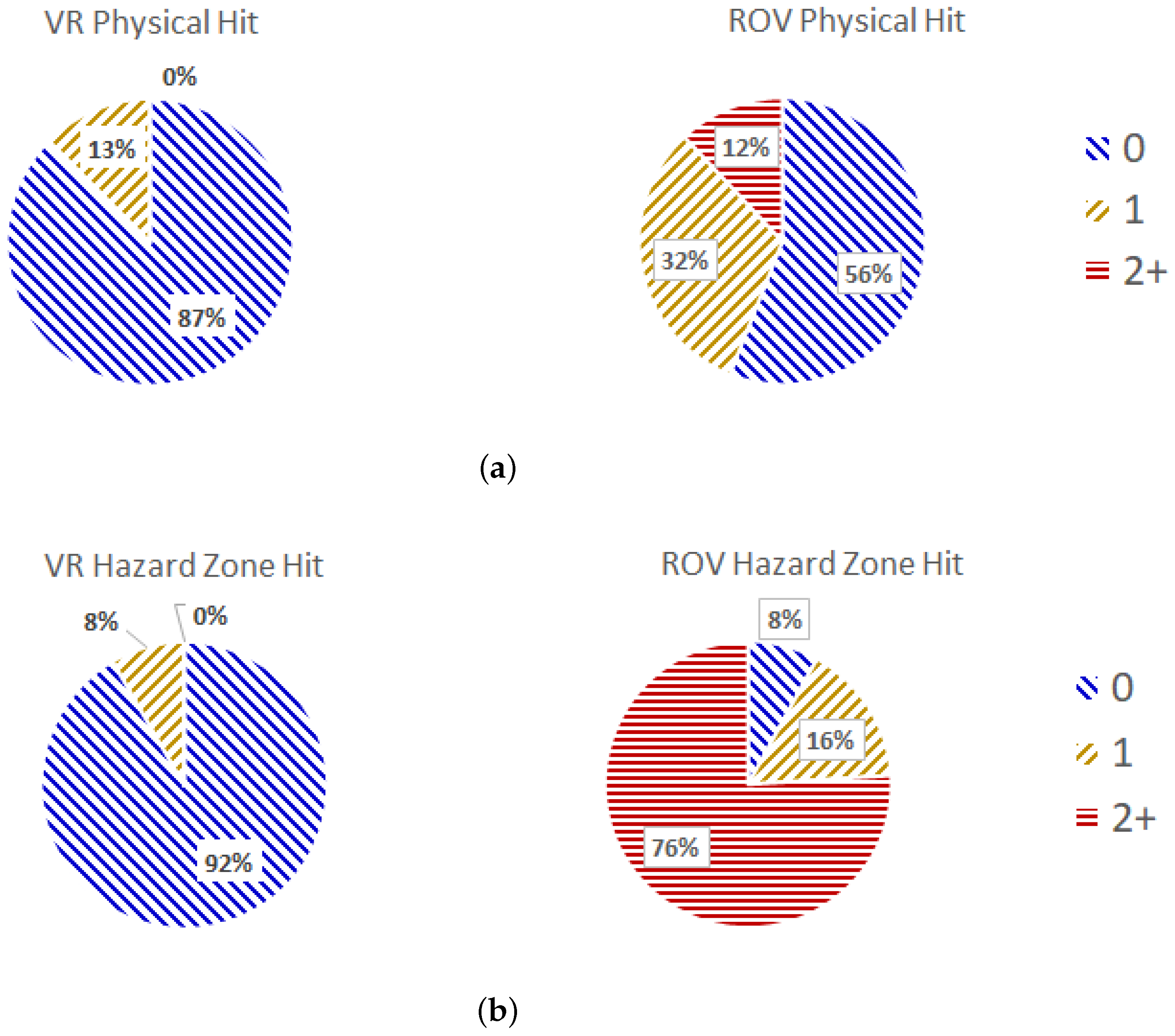
Figure 19 shows the performance of study participants in the Navigation task in terms of collisions with physical objects or non-physical hazard zones scattered through the maze. In Figure 19a, the collisions with physical objects are compared between the ROV (right) and VR (left) sessions. Figure 19b compares the number of collisions with non-physical hazard zones between the VR (left) and the ROV (right) sessions.
Collisions: As it can be observed from Figure 19a that 87% of participants in the VR session completed the navigation tasks without hitting a single object within the maze, compared to only 56% in the ROV session. Thirteen percent of participants in the VR session hit one object while navigating the maze, compared to 32% of participants in the ROV session. No participant in the VR session collided with more than one object, while 12% of participants in the ROV session hit two or more objects within the maze.
Navigating around non-physical hazard zones in the ROV session is a much more complicated task, since these types of areas usually are difficult to spot without the benefits of VR visualization. As shown in Figure 19b, a mere 8% of participants in the ROV session completed the navigation tasks without hitting any hazard zone within the maze, compared to 92% in the VR session. Only 8% of participants in the VR session collided with one hazard zone, compared to 16% in the ROV session. A staggering 76% of participants in the ROV session hit two or more hazard zones while navigating the maze, while none of the participants in the VR session hit more than one hazard zone.
7. Conclusions and Future Work
This paper presented an integrated architecture called VETO as an interactive and immersive virtual reality environment for tele-robotics and tele-presence applications. The proposed system utilizes a two-tier client–server architecture comprising a computational server and a multitude of heterogeneous clients, ranging from virtual reality clients to robotics remote operational clients. This paper has addressed the effective integration of a diverse set of challenges by the system, including sensory fusion, heterogenous computing mechanisms for accelerating computation, cyber-physical multiplayer gameplay, and dynamic manipulation of the virtual environment, while allowing for efficient and intuitive human–robot–environment interactions.
A human usability study was designed to evaluate and validate the performance of the proposed VETO architecture with the current robotic tele-operation tools. The study showed improvements in both the speed of task completion as well as the task completion accuracy.
The design of the VETO architecture is extensible and, as such, supports a range of applications and research projects. One of the future direction of this work is to create a mechanism to utilize the sensory data from the robotics agents to build the virtual environments in real-time. In addition, we are investigating a more intuitive means of interaction with the remotely operated robots by mapping natural hand and body gestures onto the operational modes of the robotic agents via a hierarchical activity-intent recognition model.
Author Contributions
A.T., B.W. and M.B. designed and implemented the VETO framework. B.W. designed and implemented the CorssSock API. J.R. designed and implemented the user interfaces within the VETO architecture. D.M. and L.O. performed the human subject experiments. A.T. and D.L. designed and analyzed the results of the human trials. A.T. is the principal investigator for the entire project, coordinated the research tasks, and supervised the design, implementation, and analyses of the study.
Funding
The material in this paper is based upon work supported by the NASA MUREP ASTAR program under grant number NNX15AU31H, and by the US Army Research Laboratory and the US Department of Defense under grant numbers W911NF-15-1-0024, W911NF-15-1-0455, and W911NF-16-1-0473. This support does not necessarily imply endorsement by NASA, DoD, or ARL.
Conflicts of Interest
The authors declare no conflict of interest. The founding sponsors had no role in the design of the study; in the collection, analyses, or interpretation of data; in the writing of the manuscript, and in the decision to publish the results.
Abbreviations
The following abbreviations are used in this manuscript:
| HMD | Head Mounted Display |
| VETO | Virtual Environment for TeleOperation |
| VR | Virtual Reality |
| AR | Augmented Reality |
References
- Chen, J.Y.; Haas, E.C.; Barnes, M.J. Human performance issues and user interface design for teleoperated robots. IEEE Trans. Syst. Man Cybern. Part C Appl. Rev. 2007, 37, 1231–1245. [Google Scholar] [CrossRef]
- Nickerson, R. Pioneering the personal robotics industry. Technologies for Practical Robot Applications, 2009. In Proceedings of the IEEE International Conference on TePRA 2009, Woburn, MA, USA, 9–10 November 2009; pp. 179–185. [Google Scholar]
- Nielsen, C.W.; Goodrich, M.A.; Ricks, R.W. Ecological interfaces for improving mobile robot teleoperation. IEEE Trans. Robot. 2007, 23, 927–941. [Google Scholar] [CrossRef]
- Oblinger, D. Simulations, Games, and Learning. In ELI White Paper; Eduacause: Louisville, CO, USA, 2006. [Google Scholar]
- Earnshaw, R.A. Virtual Reality Systems; Academic Press: Cambridge, MA, USA, 2014. [Google Scholar]
- Burdea, G.C. Invited review: The synergy between virtual reality and robotics. IEEE Trans. Robot. Autom. 1999, 15, 400–410. [Google Scholar] [CrossRef]
- Epic Games. Unreal Engine 4. Available online: https://www.unrealengine.com/what-is-unreal-engine-4 (accessed on 14 April 2014).
- Tavakkoli, A. Game Development and Simulation with Unreal Technology; CRC Press: Boca Raton, FL, USA, 2015. [Google Scholar]
- Wilson, B. CrossSock. Available online: https://github.com/CAVE-Lab/CrossSock (accessed on 1 March 2017).
- Shiroma, N.; Sato, N.; Chiu, Y.H.; Matsuno, F. Study on effective camera images for mobile robot teleoperation. In Proceedings of the 13th IEEE International Workshop on Robot and Human Interactive Communication ROMAN, 2004, Okayama, Japan, 22 September 2004; pp. 107–112. [Google Scholar]
- Farkhatdinov, I.; Ryu, J.H.; Poduraev, J. A user study of command strategies for mobile robot teleoperation. Intell. Serv. Robot. 2009, 2, 95–104. [Google Scholar] [CrossRef]
- Tsumaki, Y.; Takahashi, M.; Yoon, W.K.; Uchiyama, M. Virtual radar: An obstacle information display system for teleoperation. In Proceedings of the International Conference on Robotics and Automation ICRA’02, Washington, DC, USA, 11–15 May 2002; Volume 2, pp. 1185–1190. [Google Scholar]
- Wang, M.; Liu, J.N. Interactive control for Internet-based mobile robot teleoperation. Robot. Auton. Syst. 2005, 52, 160–179. [Google Scholar] [CrossRef]
- Suzuki, T.; Fujii, T.; Yokota, K.; Asama, H.; Kaetsu, H.; Endo, I. Teleoperation of multiple robots through the internet. In Proceedings of the 5th IEEE International Workshop on Robot and Human Communication, New Orleans, LA, USA, 8–11 September 1996; pp. 84–89. [Google Scholar]
- Dryanovski, I.; Valenti, R.G.; Xiao, J. Fast visual odometry and mapping from RGB-D data. In Proceedings of the IEEE International Conference on Robotics and Automation (ICRA), Karlsruhe, Germany, 6–10 May 2013; pp. 2305–2310. [Google Scholar]
- Lentaris, G.; Stamoulias, I.; Soudris, D.; Lourakis, M. HW/SW Codesign and FPGA Acceleration of Visual Odometry Algorithms for Rover Navigation on Mars. IEEE Trans. Circuits Syst. Video Technol. 2016, 26, 1563–1577. [Google Scholar] [CrossRef]
- Monferrer, A.; Bonyuet, D. Cooperative robot teleoperation through virtual reality interfaces. In Proceedings of the Information Visualisation, London, UK, 10–12 July 2002; pp. 243–248. [Google Scholar]
- Lin, Q.; Kuo, C. Virtual tele-operation of underwater robots. In Proceedings of the IEEE International Conference on IEEE Robotics and Automation, Albuquerque, NM, USA, 20–25 April 1997; Volume 2, pp. 1022–1027. [Google Scholar]
- Tang, X.; Yamada, H.; Yusof, A.A. Virtual reality-based master-slave control system for construction tele-operation robot. In Proceedings of the 2009 IEEE International Conference on Intelligent Computing and Intelligent Systems, Shanghai, China, 20–22 November 2009. [Google Scholar]
- Baizid, K.; Chellali, R.; Hauptman, T. ViRAT: An advanced multi-robots platform. In Proceedings of the 7th IEEE Conference on IEEE Industrial Electronics and Applications (ICIEA), Singapore, 18–20 July 2012; pp. 564–569. [Google Scholar]
- Steuer, J. Defining Virtual Reality: Dimensions Determining Telepresence. J. Commun. 1992, 42, 73–93. [Google Scholar] [CrossRef] [Green Version]
- Torjo, J. Boost. Asio C++ Network Programming; Packt Publishing Ltd.: Birmingham, UK, 2013. [Google Scholar]
- Pedersen, M.V.; Heide, J.; Fitzek, F.H. Kodo: An open and research oriented network coding library. In Proceedings of the International Conference on Research in Networking, Valencia, Italiy, 9–13 May 2011; Springer: Berlin, Germany, 2011; pp. 145–152. [Google Scholar]
Figure 1.
The immersion allowed by the use of a virtual reality environment for the tele-operation of remote robotic agents. (a) Intuitive User Interface (UI) for human operation of robots. (b) Controlling a robot with the intuitive UI.
Figure 1.
The immersion allowed by the use of a virtual reality environment for the tele-operation of remote robotic agents. (a) Intuitive User Interface (UI) for human operation of robots. (b) Controlling a robot with the intuitive UI.

Figure 2.
High-level class overview of the CrossSock Application Programming Interface (API).

Figure 3.
Types related to the low-level socket API.

Figure 4.
Classes related to the low-level socket API.

Figure 5.
Classes and types related to the low-level system utility API.

Figure 6.
Classes and types related to the high-level packet API.

Figure 7.
Classes and types related to the high-level client API.

Figure 8.
Classes and types related to the high-level server API.

Figure 9.
An outline of the CrossSock connection process, showing tasks in chronological order. The tasks that are executed on the server are shown in red, and the tasks that are executed by the client are shown in blue.
Figure 9.
An outline of the CrossSock connection process, showing tasks in chronological order. The tasks that are executed on the server are shown in red, and the tasks that are executed by the client are shown in blue.

Figure 10.
An overview of the VETO architecture’s three major components.

Figure 11.
An overview of the VETO architecture’s network communications.

Figure 12.
High-level class overview of the VETO architecture.

Figure 13.
An example of using the VETO (Virtual Environment for Tele-Operation) architecture’s In-Game Editor. In this example, a bench is being placed in the virtual environment.
Figure 13.
An example of using the VETO (Virtual Environment for Tele-Operation) architecture’s In-Game Editor. In this example, a bench is being placed in the virtual environment.

Figure 14.
A robot being piloted manually with the VETO architecture (a) and optional Laser Range Finder (LRF) and sonar sensor visualization (b).
Figure 14.
A robot being piloted manually with the VETO architecture (a) and optional Laser Range Finder (LRF) and sonar sensor visualization (b).

Figure 15.
A robot being driven automatically with the VETO architecture through path planning and following (a) and an unknown obstacle visualized as a proximity warning (b).
Figure 15.
A robot being driven automatically with the VETO architecture through path planning and following (a) and an unknown obstacle visualized as a proximity warning (b).

Figure 16.
The virtual environment, as seen with the lights on (a) and lights off (b).

Figure 17.
(a) The ROV session view while the subject performs a navigation task. (b) The virtual reality (VR) view as seen by a subject performing an exploration task.
Figure 17.
(a) The ROV session view while the subject performs a navigation task. (b) The virtual reality (VR) view as seen by a subject performing an exploration task.

Figure 18.
Box and whiskers plots: (a) Results of the Navigation task in VR session (left) and ROV session (right). (b) Results of the Exploration task in the VR (left) and ROV (right) sessions. The vertical axis shows the completion time for each task.
Figure 18.
Box and whiskers plots: (a) Results of the Navigation task in VR session (left) and ROV session (right). (b) Results of the Exploration task in the VR (left) and ROV (right) sessions. The vertical axis shows the completion time for each task.

Figure 19.
Physical and hazard zone hits: (a) physical hits in the VR session (left) and the ROV session (right); (b) hazard zone hits in the VR (left) and the ROV (right) sessions.
Figure 19.
Physical and hazard zone hits: (a) physical hits in the VR session (left) and the ROV session (right); (b) hazard zone hits in the VR (left) and the ROV (right) sessions.

© 2018 by the authors. Licensee MDPI, Basel, Switzerland. This article is an open access article distributed under the terms and conditions of the Creative Commons Attribution (CC BY) license (http://creativecommons.org/licenses/by/4.0/).
Share and Cite
MDPI and ACS Style
Wilson, B.; Bounds, M.; McFadden, D.; Regenbrecht, J.; Ohenhen, L.; Tavakkoli, A.; Loffredo, D. VETO: An Immersive Virtual Environment for Tele-Operation. Robotics 2018, 7, 26. https://doi.org/10.3390/robotics7020026
AMA Style
Wilson B, Bounds M, McFadden D, Regenbrecht J, Ohenhen L, Tavakkoli A, Loffredo D. VETO: An Immersive Virtual Environment for Tele-Operation. Robotics. 2018; 7(2):26. https://doi.org/10.3390/robotics7020026
Chicago/Turabian StyleWilson, Brandon, Matthew Bounds, David McFadden, Jace Regenbrecht, Loveth Ohenhen, Alireza Tavakkoli, and Donald Loffredo. 2018. "VETO: An Immersive Virtual Environment for Tele-Operation" Robotics 7, no. 2: 26. https://doi.org/10.3390/robotics7020026
Note that from the first issue of 2016, this journal uses article numbers instead of page numbers. See further details here.