Optimal Kinematic Design of a 6-UCU Kind Gough-Stewart Platform with a Guaranteed Given Accuracy


School of Mechanical Engineering, Hunan Institute of Science and Technology, Yueyang 414006, China
Robotics 2018, 7(2), 30; https://doi.org/10.3390/robotics7020030
Submission received: 24 April 2018
/
Revised: 11 June 2018
/
Accepted: 15 June 2018
/
Published: 18 June 2018
(This article belongs to the Special Issue Kinematics and Robot Design I, KaRD2018)
Abstract
:The 6-UCU (U-universal joint; C-cylinder joint) kind Gough-Stewart platform is extensively employed in motion simulators due to its high accuracy, large payload, and high-speed capability. However, because of the manufacturing and assembling errors, the real geometry may be different from the nominal one. In the design process of the high-accuracy Gough-Stewart platform, one needs to consider these errors. The purpose of this paper is to propose an optimal design method for the 6-UCU kind Gough-Stewart platform with a guaranteed given accuracy. Accuracy analysis of the 6-UCU kind Gough-Stewart platform is presented by considering the limb length errors and joint position errors. An optimal design method is proposed by using a multi-objective evolutionary algorithm, the non-dominated sorting genetic algorithm II (NSGA-II). A set of Pareto-optimal parameters was found by applying the proposed optimal design method. An engineering design case was studied to verify the effectiveness of the proposed method.
1. Introduction
With the advantages of high rigidity, high precision, and large carrying capacity, Gough-Stewart platforms (GSPs) are extensively used in virtual-reality motion simulators [1]. Many scholars studied the optimal design of the 6-UPS kind GSP [1], where U stands for the universal joint, P for the prismatic joint, and S for the spherical joint. When compared with spherical joints, universal joints can bear more tension [2]. Universal joints are extensively used as the passive joints of GSPs to connect hydraulic cylinders or electric cylinders to the moving platform and fixed base. Universal joints are used as the passive joints of the universal tyre test machine designed by Gough et al. [3,4,5], the motion simulator patented by Cappel [6], commercial flight simulators [7], the Ampelmann system [8], the Moog FCS 5000E motion base [9], the VARIAX machine tool [10], and the AMiBA hexapod telescope mount [11]. Universal joints are also used as the passive joints of the docking test system, and about 60 motion simulators designed by the team of Professor Junwei Han at the Harbin Institute of Technology, China. The cylinders of the hydraulic and electric actuators that can not only translate along the axis, but also rotate along the axis are cylindrical joints instead of prismatic ones. These GSPs are 6-UCU parallel manipulators [12,13], where C stands for the cylinder joint.
In highly accurate positioning applications, such as the docking test systems, high accuracy is required to achieve good simulation results. in China, the translational motion errors of the moving platform must be less than 1 mm in the whole workspace of the docking test system [14]. Many researchers studied the accuracy analysis of GSPs. Wang and Masory studied the effects of manufacturing errors on the accuracy of a GSP by modeling the GSP as serial legs based on the Denavit–Hartenberg method [15]. Ropponen and Arai presented the error model of a modified GSP by using the differentiation method [16]. Patel and Ehmann established an error model of a GSP, addressing all possible sources of errors [17]. Wang and Ehmann developed first- and second-order error models of a GSP [18]. Masory et al. presented an effective method of identifying kinematic parameters of a GSP using pose measurements [19]. Cong et al. developed a kinematic calibration method of a GSP by using a three-dimensional coordinate measuring machine containing actuator errors and passive joint errors [20]. Dai et al. proposed an accuracy analysis method for a docking test system [14]. Merlet and Daney proposed an optimal method of parallel manipulator considering manufacturing errors by using interval analysis [21,22,23]. Because of the dependence of the variables, a high level of expertise in interval analysis is needed for the proper usage of parallel manipulators [22]. To the best of our knowledge, there are few papers considering the errors of a GSP in optimal design processes.
In the optimal design process of a high-precision GSP, one needs to find the optimal solutions which meet the given accuracy requirement. An optimal design method for a GSP is proposed in this paper, so as to meet these accuracy requirements.
2. Differential Error Model
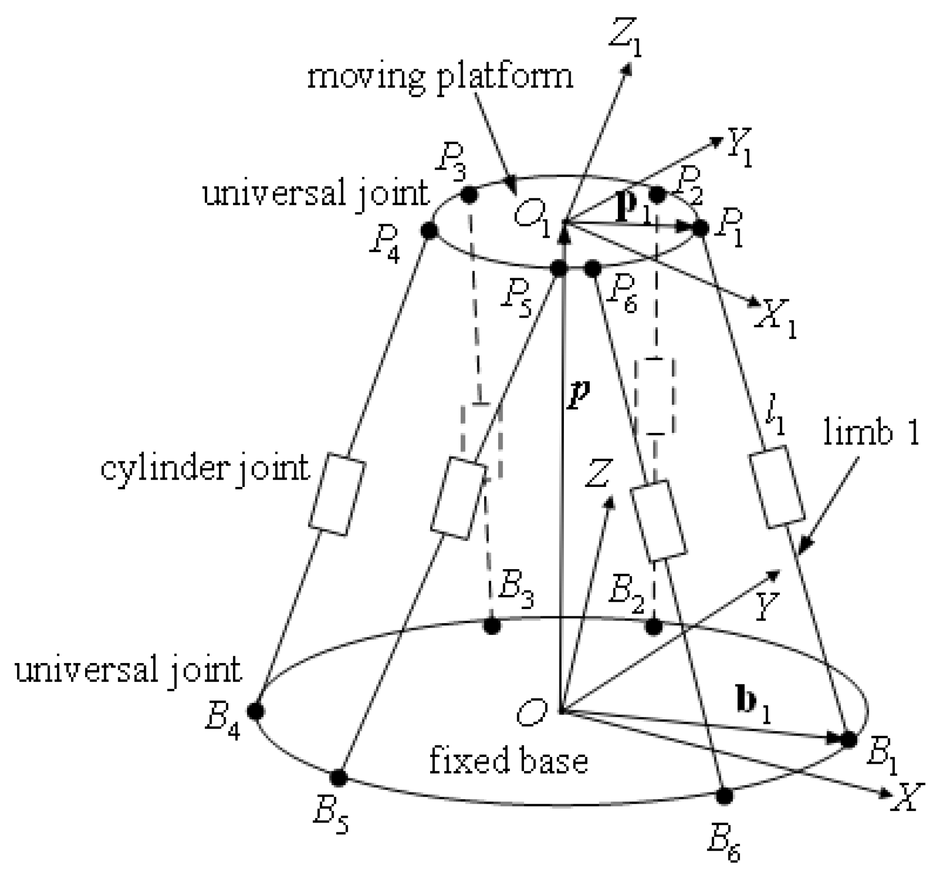
In this section, the relationship between the structural errors and end-point errors of a 6-UCU kind GSP is discussed. The 6-UCU kind GSP consisted of a moving platform, a fixed base, and six limbs, as shown in Figure 1 and Figure 2. The ith limb was connected to the fixed base via a universal joint, whose joint center point is denoted as , and connected to the mobile platform via a universal joint with center , as shown in Figure 2. For convenience, a Cartesian coordinate frame, , was attached to the moving platform with origin . A Cartesian coordinate frame, , was attached to the fixed base with origin .
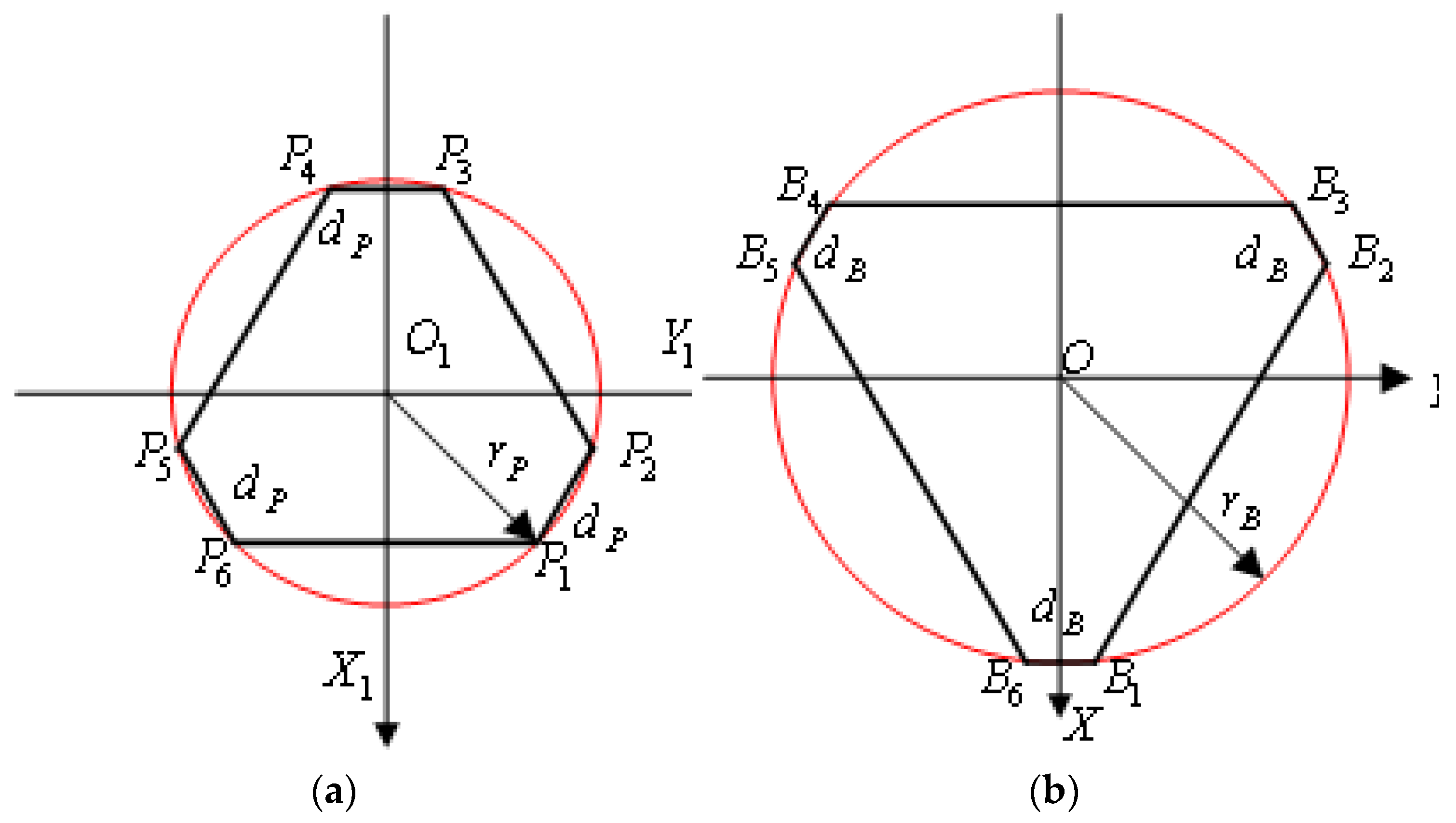
The positions of the universal joints attached to the moving platform and the fixed base of the GSP formed semi-hexagons, as shown in Figure 3, where is the radius of the platform-joint attachment circle, is the distance between the shorter edges of the attachment point semi-hexagon on the moving platform, is the radius of the base-joint attachment circle, and is the distance between the shorter edges of the attachment point semi-hexagon on the fixed base.
Referring to Figure 1 and Figure 2, the position vector of expressed in the frame could be written as
where is the rotation matrix from the frame to , is the position coordinate of the point measured in the frame , is the position coordinate of the point measured in the frame , is expressed as in the frame , is the coordinate of the point measured in the frame , is the distance from the point to the lower plane of the piston, is the distance from the point to the lower plane of the piston, is the unit vector of , and are the unit vectors of fixed to the cylinder and piston, respectively, and .
and are
where T is the matrix transpose, is the z coordinate of the upper universal joint of the ith limb in the frame , is the z coordinate of the lower universal joint of the ith limb in the frame , and and are as follows:
where
For the ith leg, the limb length was derived as
where is the length of .
Differentiating Equation (1), we obtained
where could be rewritten as follows, according to Reference [16]:
where is the orientation error vector of the moving platform in the frame , and is the translational error vector of the moving platform in the frame .
Multiplication of on both sides of Equation (10) yielded
Since , , , and , we had , , and . Therefore, Equation (11) could be rewritten as
could be derived as
Once all six limbs were assembled, the errors could be expressed as
where
If the inverse of existed, then could be derived as
The first term on the right side represents the actuation-induced error, and the second term is the error caused by the position errors of the joints [16].
3. Optimal Design Method
In engineering, we may assume that the manufacturing tolerances on the geometrical parameters are bounded and the maximum values of and are known as a function of the manufacturing method. The maximum values of for the optimal design solutions had to be lower than the given accuracy by customers, before being dealt with as a constraint in the optimal design process in this paper.
Many scholars studied the optimal design of a GSP with only one optimal solution [24]. In practice, many different functional requirements of robots are intended to be satisfied [25]; thus, it is more appropriate to have multiple optimization solutions after the optimal kinematic design [24]. The condition number and determinant of the kinematic Jacobian matrix, , of a GSP were extensively used as optimal design objectives [24]; therefore, they were chosen as objective functions in the optimal design process in this paper. Accordingly, they were defined as
where and are the maximum and minimum singular values of at one pose, respectively, and is the determinant of .
In the optimal design process, evolutionary algorithms are extensively used to search the optimal solutions [26]. In this paper, the elitist non-dominated sorting genetic algorithm version II (NSGA-II), developed by Deb et al. [27], was employed to solve the multi-objective optimal design problems of the 6-UCU kind GSP, due to its good spread of solutions and convergence to obtain the Pareto front. Real-coded NSGA-II with a simulated binary crossover (SBX) operator [28] and a polynomial mutation operator [29] were adopted in this paper to search the minimum values of the objective functions. The parameters of the NSGA-II are shown in Table 1.
The optimal design procedures were proposed as described below.
Step 1. The customers usually provided the maximum motion requirements for each degree of freedom (DOF), as shown in Table 2.
We transformed the requirements of the customer to 12 typical trajectories along six single axes [24]. Two typical travel trajectories of translation along the X axis were
where t is the run time.
Step 2. At each pose, was calculated using Equation (22). When it was at or near the singularity, calculating using Equation (21) was potentially wrong. We used another method to solve this problem, as follows: if , then ; if , was calculated using Equation (21). In the searching process, the guaranteed accuracy was given, and then it was dealt with as a constraint. The penalty function is the most often used technique in constrained optimization [26]; however, the penalty coefficients are very difficult to choose appropriately [30]. We handled the constraint as follows: if was in the required range, was calculated using Equation (22), and was calculated using Equation (23). Otherwise, and . A subprogram was subsequently created to calculate the maximum value of and the minimum value of for all 12 typical trajectories.
where , , and are the required maximum linear displacement positioning errors along the X, Y, and Z axes, respectively; , , and are the required maximum angular displacement positioning errors along the X, Y, and Z axes, respectively.
Step 3. was set as the maximum value of calculated in step 2, and was set as the minimum value of calculated in step 2.
Step 4. The design variables were chosen as , , , , and , where was the height of the upper universal joint plane to the lower universal joint plane at the home position. and . NSGA-II was used to minimize the objective functions, and , simultaneously.
For other requirements, the 12 typical trajectories were replaced by all the typical trajectories in the special applications. In the optimal kinematic design of a flight simulator, 31 typical trajectories of a Boeing 747 were considered in the design process by Advani [31]. If one desires a singularity-free workspace, as for motion simulators, the 12 typical trajectories in Step 2 would be replaced by all the typical trajectories and the 64 extreme positions [24,31].
4. Case Study
A case study is presented in this section to show the effectiveness of the proposed optimal design method. For this specific case, the requirements of the customer are shown in Table 3.
From a practical consideration, the ranges of the parameters were chosen as follows:
, , , , , , , and . The range of every element of and were in the range .
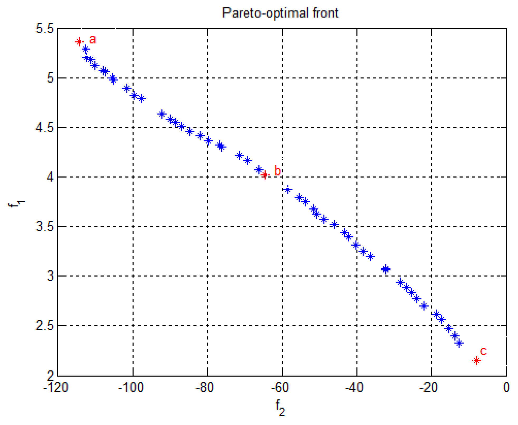
After applying the proposed optimization process, as outlined in Section 3, 50 optimal solutions and the Pareto-optimal front were found, as shown in Figure 4. Lastly, there were three optimum design points, labeled as a, b, and c, whose corresponding objective values and design parameters are shown in Table 4. As seen in Table 4, the maximum errors of all the linear displacements were lower than 1 mm, and the maximum errors of all the angular displacements were lower than 0.1°. Therefore, all the requirements by the customer, given in Table 3, were met. This showed the effectiveness of the proposed method for the optimal design purpose.
5. Conclusions
Motion simulators extensively use 6-UCU kind GSPs. A differential error model for a 6-UCU kind GSP was derived in this paper, and contained both the actuation-induced error and the error caused by the position errors of the joints. The guaranteed given accuracy was used as a constraint in the optimal design process of the high-accuracy motion simulators. An optimal kinematic design method was proposed by using the multi-objective evolutionary algorithm, NSGA-II. If was near or at the singularity pose, the inverse of potentially did not exist. could be wrongly calculated using Equation (21). In order to solve this problem, a method was presented where the condition number of was compared with a large number. Another engineering method was proposed to handle the accuracy requirement constraints in the optimal design process. Multiple optimization solutions were found following implementation of the optimal kinematic design.
The effectiveness of the proposed method was verified through a practical optimal design case. The proposed optimal design method can be used as a guideline for the practical design of GSPs used in other applications with high-accuracy requirements.
Conflicts of Interest
The authors declare no conflict of interest.
References
- Merlet, J.P. Parallel Robots, 2nd ed.; Springer: Dordrecht, The Netherlands, 2006; pp. 77–78. ISBN 978-1-4020-4132-7. [Google Scholar]
- Huang, Z.; Kong, L.F.; Fang, Y.F. Mechanism Theory of Parallel Robotic Manipulator and Control; China Mechanical Press: Beijing, China, 1997; pp. 306–308. ISBN 7-111-05812-7. (In Chinese) [Google Scholar]
- Fichter, E.; Kerr, D.; Rees-Jones, J. The Gough—Stewart platform parallel manipulator: A retrospective appreciation. Proc. Inst. Mech. Eng. Part C J. Mech. Eng. Sci. 2009, 223, 243–281. [Google Scholar] [CrossRef]
- Gough, V.E.; Whitehall, S.G. Universal Tyre Testing Machine. In Proceedings of the 9th International Automobile Technical Congress, Bursa, Turkey, 7–8 May 2018. [Google Scholar]
- Stewart, D. A Platform with six degrees of freedom. Proc. Inst. Mech. Eng. 1965, 180, 371–386. [Google Scholar] [CrossRef]
- Cappel, K.L. Motion Simulator. U.S. Patent 3,295,224, 3 January 1967. [Google Scholar]
- Ma, O. Mechanical Analysis of Parallel Manipulators with Simulation, Design and Control Applications. Ph.D. Thesis, McGill University, Montreal, QC, Canada, 1991. [Google Scholar]
- Cerda Salzmann, D.J. Ampelmann: Development of the Access System for Offshore Wind Turbines. Ph.D. Thesis, Delft University of Technology, Delft, The Netherlands, 2010. [Google Scholar]
- Blaise, J.; Bonev, I.; Monsarrat, B.; Briot, S.; Lambert, J.M.; Perron, C. Kinematic characterisation of hexapods for industry. Ind. Robot Int. J. 2010, 37, 79–88. [Google Scholar] [CrossRef]
- VARIAX: The Machine Tool of the Future-Today! Giddings & Lewis, Inc.: Fond Du Lac, WI, USA, 1994.
- Koch, P.M.; Kesteven, M.; Nishioka, H.; Jiang, H.; Lin, K.Y.; Umetsu, K.; Huang, Y.-D.; Raffin, P.; Chen, K.J.; Ibañez-Romano, F. The AMiBA hexapod telescope mount. Astrophys. J. 2009, 694, 1670–1684. [Google Scholar] [CrossRef]
- Liu, G.; Zheng, S.; Ogbobe, P.; Han, J. Inverse kinematic and dynamic analyses of the 6-UCU parallel manipulator. Appl. Mech. Mater. 2012, 127, 172–180. [Google Scholar] [CrossRef]
- Liu, G.; Qu, Z.; Liu, X.; Han, J. Singularity analysis and detection of 6-UCU parallel manipulator. Robot Comput. Integr. Manuf. 2014, 30, 172–179. [Google Scholar] [CrossRef]
- Dai, X.; Huang, Q.; Han, J.; Li, H. Accuracy Synthesis of Stewart Platform used in Testing System for Spacecraft Docking Mechanism. In Proceedings of the International Conference on Measuring Technology and Mechatronics Automation, ICMTMA’09, Zhangjiajie, China, 11–12 April 2009; Volume 3, pp. 7–10. [Google Scholar] [CrossRef]
- Wang, J.; Masory, O. On the Accuracy of a Stewart Platform-Part I: The Effect of Manufacturing Tolerances. In Proceedings of the IEEE International Conference on Robotics and Automation, Atlanta, GA, USA, 2–6 May 1993; pp. 114–120. [Google Scholar] [CrossRef]
- Ropponen, T.; Arai, T. Accuracy Analysis of a Modified Stewart Platform Manipulator. In Proceedings of the IEEE International Conference on Robotics and Automation, Nagoya, Japan, 21–27 May 1995; pp. 521–525. [Google Scholar] [CrossRef]
- Patel, A.J.; Ehmann, K.F. Volumetric error analysis of a Stewart platform-based machine tool. CIRP Ann. Manuf. Technol. 1997, 46, 287–290. [Google Scholar] [CrossRef]
- Wang, S.M.; Ehmann, K.F. Error model and accuracy analysis of a six-DOF Stewart platform. J. Manuf. Sci. Eng. 2002, 124, 286–295. [Google Scholar] [CrossRef]
- Masory, O.; Wang, J.; Zhuang, H. On the Accuracy of a Stewart Platform—Part II: Kinematic Calibration and Compensation. In Proceedings of the IEEE International Conference on Robotics and Automation, Atlanta, GA, USA, 2–6 May 1993; pp. 725–731. [Google Scholar] [CrossRef]
- Cong, D.; Yu, D.; Han, J. Kinematics accuracy analysis and error compensation of Stewart platform. J. Eng. Des. 2006, 13, 162–165. (In Chinese) [Google Scholar]
- Merlet, J.P.; Daney, D. Dimensional Synthesis of Parallel Robots with a Guaranteed Given Accuracy over a Specific Workspace. In Proceedings of the IEEE International Conference on Robotics and Automation, ICRA 2005, Barcelona, Spain, 18–22 April 2005; pp. 942–947. [Google Scholar] [CrossRef] [Green Version]
- Merlet, J.-P.; Daney, D. Appropriate Design of Parallel Manipulators. In Smart Devices and Machines for Advanced Manufacturing; Wang, L., Xi, F., Eds.; Springer: London, UK, 2008; pp. 1–25. ISBN 978-1-84800-146-6. [Google Scholar]
- Merlet, J.P. Interval analysis and reliability in robotics. Int. J. Reliab. Saf. 2009, 3, 104–130. [Google Scholar] [CrossRef]
- Liu, G.; Qu, Z.; Han, J.; Liu, X. Systematic optimal design procedures for the Gough-Stewart platform used as motion simulators. Ind. Robot 2013, 40, 550–558. [Google Scholar] [CrossRef]
- Angeles, J.; Park, F.C. Design and performance evaluation. In Springer Handbook of Robotics, 2nd ed.; Siciliano, B., Khatib, O., Eds.; Springer: Berlin, Germany, 2016; pp. 399–418. ISBN 978-3-319-32550-7. [Google Scholar]
- Yu, X.; Gen, M. Introduction to Evolutionary Algorithms; Springer: London, UK, 2010; pp. 3–8. ISBN 978-1-84996-128-8. [Google Scholar]
- Deb, K.; Pratap, A.; Agarwal, S.; Meyarivan, T.A.M.T. A fast and elitist multiobjective genetic algorithm: NSGA-II. IEEE Trans. Evolut. Comput. 2002, 6, 182–197. [Google Scholar] [CrossRef] [Green Version]
- Deb, K.; Agrawal, R.B. Simulated binary crossover for continuous search space. Complex Syst. 1994, 9, 1–34. [Google Scholar]
- Deb, K.; Goyal, M. A combined genetic adaptive search (GeneAS) for engineering design. Comput. Sci. Inf. Syst. 1996, 26, 30–45. [Google Scholar]
- Deb, K. An efficient constraint handling method for genetic algorithms. Comput. Method Appl. Mech. 2000, 186, 311–338. [Google Scholar] [CrossRef] [Green Version]
- Advani, S.K. The Kinematic Design of Flight Simulator Motion Bases. PhD. Dissertation, TU Delft, Delft, The Netherlands, 1998; pp. 103–191. [Google Scholar]
Figure 1.
The 6-UCU (U—universal joint; C—cylinder joint) kind Gough-Stewart platform (GSP).

Figure 2.
Schematic of the 6-UCU kind GSP.

Figure 3.
Schematic of the universal joint positions. (a) Moving platform; and (b) fixed base.

Figure 4.
Pareto-optimal front of the solutions.


Table 1.
Parameters of the non-dominated sorting genetic algorithm version II (NSGA-II).
| Number of Iterations | 1000 |
|---|---|
| Population size | 50 |
| Crossover probability | 0.9 |
| Mutation probability | 0.1 |
| Distribution index for the simulated binary crossover (SBX) | 20 |
| Distribution index for the polynomial mutation | 20 |
Table 2.
Typical requirements by customers.
| Payload | |||
|---|---|---|---|
| Degree of Freedom (DOF) | Maximum Excursion | Speed | Acceleration |
| Roll | ±(°) | ±(°/s) | ±(°/s2) |
| Pitch | ±(°) | ±(°/s) | ±(°/s2) |
| Yaw | ±(°) | ±(°/s) | ±(°/s2) |
| Surge | ±(m) | ±(m/s) | ±(m/s2) |
| Sway | ±(m) | ±(m/s) | ±(m/s2) |
| Heave | ±(m) | ±(m/s) | ±(m/s2) |
Table 3.
Requirements of the customer.
| Payload | 10,000 kg | ||
|---|---|---|---|
| Maximum Position Errors | Linear Travel | 1 mm | |
| Angular Travel | 0.1° | ||
| DOF | Maximum Excursion | Speed | Acceleration |
| Roll | ±25° | ±20°/s | ±210°/s2 |
| Pitch | ±25° | ±20°/s | ±210°/s2 |
| Yaw | ±30° | ±20°/s | ±210°/s2 |
| Surge | ±1 m | ±0.7 m/s | ±10 m/s2 |
| Sway | ±1 m | ±0.7 m/s | ±10 m/s2 |
| Heave | ±0.8 m | ±0.6 m/s | ±10 m/s2 |
Table 4.
Objective functions values from the Pareto sets and their corresponding design variables.
| a | b | c | |
|---|---|---|---|
| (m) | 0.3409 | 0.3489 | 0.2500 |
| (m) | 1.6915 | 0.5177 | 0.2200 |
| (m) | 3.0000 | 2.9981 | 2.6552 |
| (m) | 3.0000 | 2.4046 | 1.2128 |
| (m) | 2.4002 | 2.4044 | 2.4363 |
| −114.2709 | −64.5399 | −8.0017 | |
| 5.3615 | 4.0201 | 2.1464 | |
| (mm) | 0.2 | 0.2 | 0.2 |
| (mm) | 0.2 | 0.2 | 0.2 |
| (mm) | 0.6 | 0.6 | 0.6 |
| (°) | 0.0022 | 0.0025 | 0.0020 |
| (°) | 0.0018 | 0.0027 | 0.0026 |
| (°) | 0.0030 | 0.0029 | 0.0030 |
© 2018 by the author. Licensee MDPI, Basel, Switzerland. This article is an open access article distributed under the terms and conditions of the Creative Commons Attribution (CC BY) license (http://creativecommons.org/licenses/by/4.0/).
Share and Cite
MDPI and ACS Style
Liu, G. Optimal Kinematic Design of a 6-UCU Kind Gough-Stewart Platform with a Guaranteed Given Accuracy. Robotics 2018, 7, 30. https://doi.org/10.3390/robotics7020030
AMA Style
Liu G. Optimal Kinematic Design of a 6-UCU Kind Gough-Stewart Platform with a Guaranteed Given Accuracy. Robotics. 2018; 7(2):30. https://doi.org/10.3390/robotics7020030
Chicago/Turabian StyleLiu, Guojun. 2018. "Optimal Kinematic Design of a 6-UCU Kind Gough-Stewart Platform with a Guaranteed Given Accuracy" Robotics 7, no. 2: 30. https://doi.org/10.3390/robotics7020030
Note that from the first issue of 2016, this journal uses article numbers instead of page numbers. See further details here.