Performance Analysis and Comparison of Bluetooth Low Energy with IEEE 802.15.4 and SimpliciTI

Abstract
:1. Introduction
2. Related Work
2.1. IEEE 802.15.4
2.2. BLE
2.3. SimpliciTI
3. Description of the Protocols
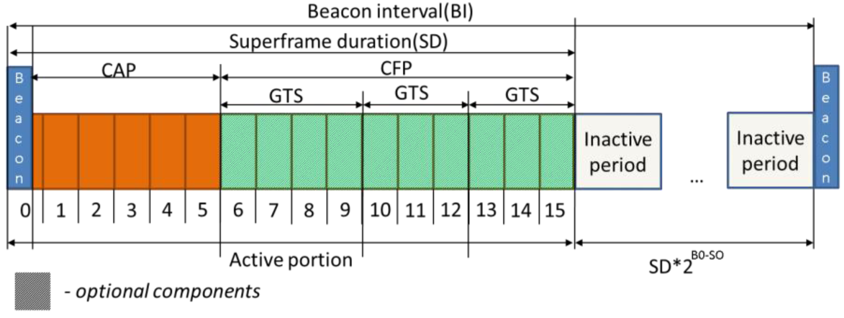
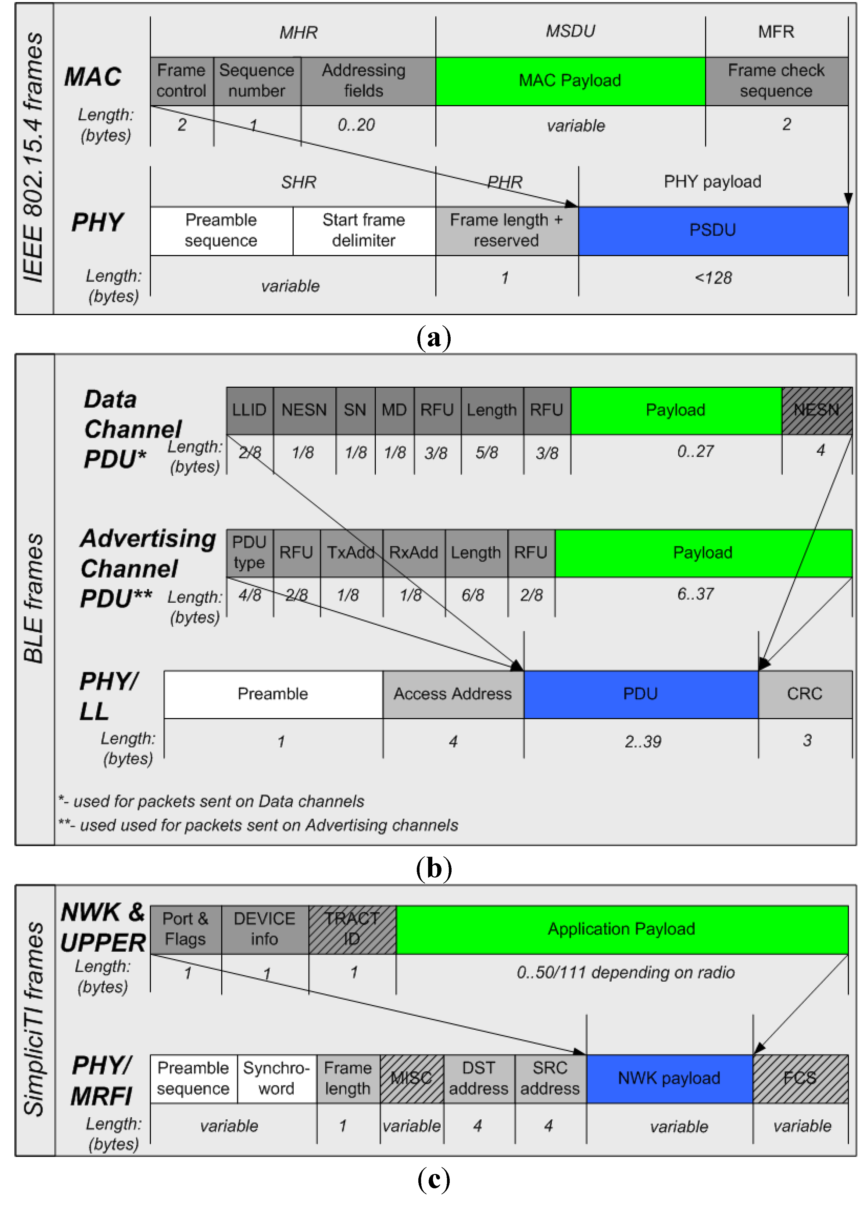
3.1. IEEE 802.15.4


3.1.1. Maximum Single-Hop Throughput
 denotes the number of MAC payload bytes in a single frame,
  stands for the radio signal propagation delay,
  account for the time required to process the n-byte data frame before the transmission and after the reception, respectively. The notation
  denotes the function that returns
  if
if  and
and  if
if  . For further details and explanations about the frame format please refer to [6].

 ) and CFP and can be calculated by Equation (5) using Equations (6) and (7) for acknowledged data transfer or Equations (8) and (9) for unacknowledged transfer. In Equations (6) and (8)
  denotes the function that rounds x to the nearest integer greater than or equal to x.


3.1.2. Minimum Single-Hop Turnaround Time


 denotes the time required for executing CSMA-CA,
  signifies the time for sending the data frame with an x-byte payload,
  indicates the time for sending the ACK frame and
  denotes the time for processing the forward frame and generating the reply frame by the layers above the ones standardized by IEEE 802.15.4 (e.g., the application layer).

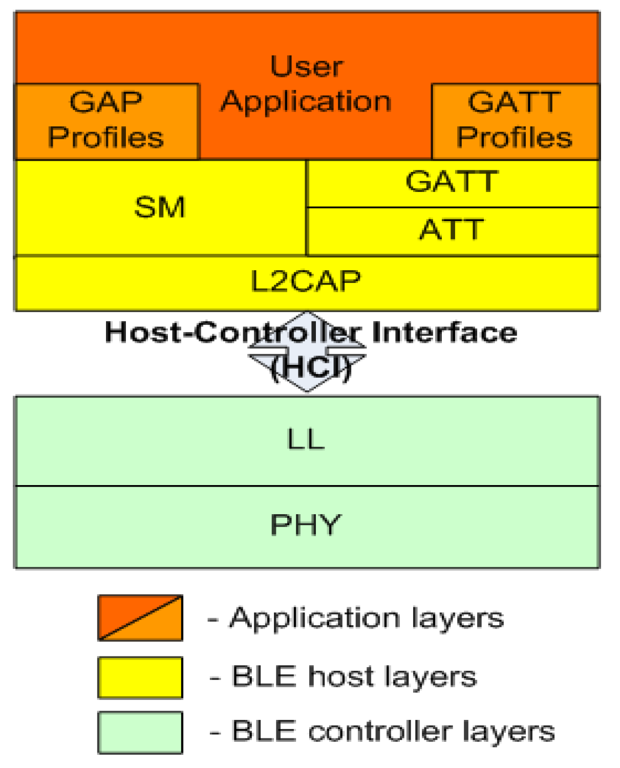
3.2. Bluetooth Low Energy


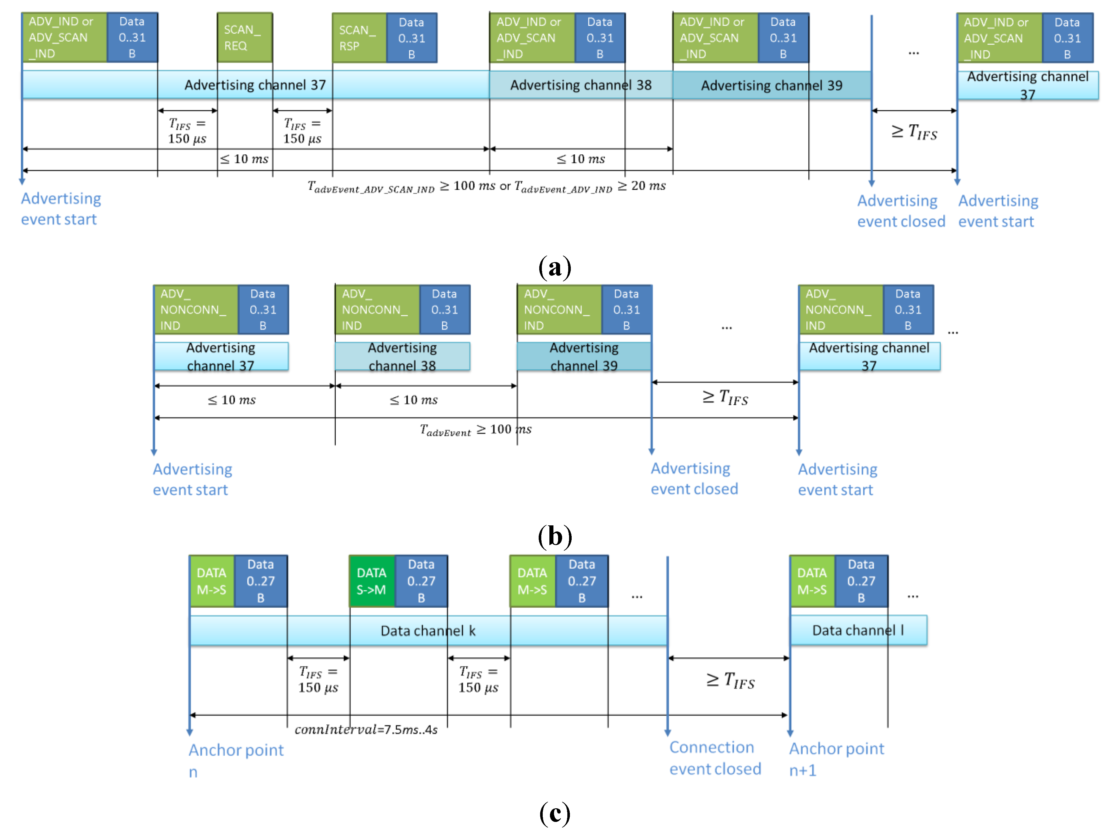
| Event type | Supported scanner responses | Minimum advInterval, ms | Maximum payload 1, bytes |
|---|---|---|---|
| AVD_IND | SCAN_REQ, CONNECT_REQ | 20 | 31/31 |
| ADV_DIRECT_IND | CONNECT_REQ | 0 | |
| ADV_NONCONN_IND | - | 100 | 31/- |
| ADV_SCAN_IND | SCAN_REQ | 100 | 31/31 |


 . Note that unlike IEEE 802.15.4, which defines the IFS as the period of time between two successive frames transmitted from a device, BLE considers IFS the time interval between two consecutive frames on one channel.
3.2.1. Maximum Throughput on Advertising Channels

 is defined from Equation (14) with advInterval value taken from Table 1.
3.2.2. Maximum Throughput on Data Channels

 (16) gives a maximum BLE LL throughput of 319.5 kbit/s and considering that the overhead introduced by the upper layers of the forward frame protocols equals 7 bytes (see [17] and [18]), we obtain a maximum application layer throughput of 236.7 kbit/s. This corresponds to the analytic results reported in [17] and [18], which are obtained using Equations (1–3) in [18] for a no packet loss scenario.
3.2.3. Minimum Turnaround Time

3.3. SimpliciTI
3.3.1. Maximum Throughput
 and
and  denote the time needed to switch between receive and transmit modes and vice versa,
  is the minimum time required to test the channel during CCA, DR stands for the used over-the-air data rate and
  and
and  are the lengths of preamble and synchroword in bytes, respectively. For SimpliciTI the
  and are the hardware parameters of the transceiver, and
  ,
,  and are set by users for the majority of transceivers.

3.3.2. Minimum Turnaround Time


4. Experiment Methodology
- defined the maximum unidirectional LL data throughput for the HW and SW implementations of the protocols;
- measured the throughput and the energy consumption of the transceivers;
- measured the minimum turnaround time;
- measured the resources required to implement the protocols.

| Parameter | Device | ||
|---|---|---|---|
| CC2510 | CC2431 | CC2540 | |
| Device type | system-on-chip (radio + 8051 microcontroller) | system-on-chip (radio + 8051 microcontroller) | system-on-chip (radio + 8051 microcontroller) |
| Microcontroller specification | Clock: 26 MHz Flash: 32 kbyte RAM: 4 kbyte | Clock: 32 MHz Flash: 128 kbyte RAM: 8 kbyte | Clock: 32 MHz Flash:256 kbyte RAM:8 kbyte |
| Radio protocol and stack version | SimpliciTI (TI SimpliciTI v1.2) | IEEE 802.15.4 (TI-MAC v1.0.1) | BLE (TI-BLE v1.2.1) |
| Frequency band | 2.4 GHz | 2.4 GHz | 2.4 GHz |
| Modulation | MSK | O-QPSK | GFSK |
| Spectrum spreading | None | DSSS | FHSS |
| Over-the-air data rate, kbit/s | 250/500 | 250 | 1000 |
| TX power range, dBm | −55…1 | −25.2…0.6 | −23…4 |
| RX sensitivity, dBm | −90 (at 250 kbit/s over-the-air data rate) | −92 | −87 (at standard mode) |
| Supply voltage, V | 2–3.6 | 2–3.6 | 2–3.6 |
| Sleep current consumption, μA | 0.5 | 0.5 | 0.9 1 |
| Price (normalized) | 0.358 | 1 | 0.341 |
5. Discussion
| Resource | Stack | |||
|---|---|---|---|---|
| SimpliciTI | TI-MAC | TI-BLE (Master) | TI-BLE (Slave) | |
| Program memory, bytes | 16,024 | 36,573 | 55,786/137,719 2 | 50,913/117,050 2 |
| Data memory 1, bytes | 3,567 | 5,438 | 10,400/12,750 2 | 9,082/10,676 2 |
 ,
,  ,
,  ,
,  ,
,  ,and
,and  for
for  and
and  for
for  (see [33]). The presented results reveal that although BLE has the highest over-the-air data rate among all protocols, SimpliciTI using the can potentially provide a higher throughput. The major reasons for this are the following. First of all, during unidirectional data transmission, SimpliciTI does not have to send any data from the receiver node to the transmitter, whilst the BLE receiver always has to send a frame in reply to each received frame to continue communication in an event (see Section 3.2). Second, unlike the two other protocols, SimpliciTI does not define the IFS between transmitted frames. Third, the payload in SimpliciTI frames is about two times larger than the one possible in a BLE data frame. The presented results also reveal that the maximum throughput possible for this protocol is 1.5 to 2 times lower than that of BLE and SimpliciTI, even though the IEEE 802.15.4 frames are capable of carrying the highest payload. The major reasons for this are as follows: the lower over-the-air data rate compared with the other technologies (see Table 2), the mandatory use of CCA before each transmission in the nonbeacon-enabled mode and in CAP of the beacon-enabled mode, and the protracted IFS between the subsequent frames. In addition, Figure 7 reveals that the maximum possible throughput for data transfer using BLE advertising channels is below 10 kbit/s for AVD_IND events and is below 2.4 kbit/s for ADV_NONCONN_IND and ADV_SCAN_IND events. Note that the presented value for BLE’s maximum throughput is calculated for the LL payload and the actual throughput for the user applications data is lower.

 and
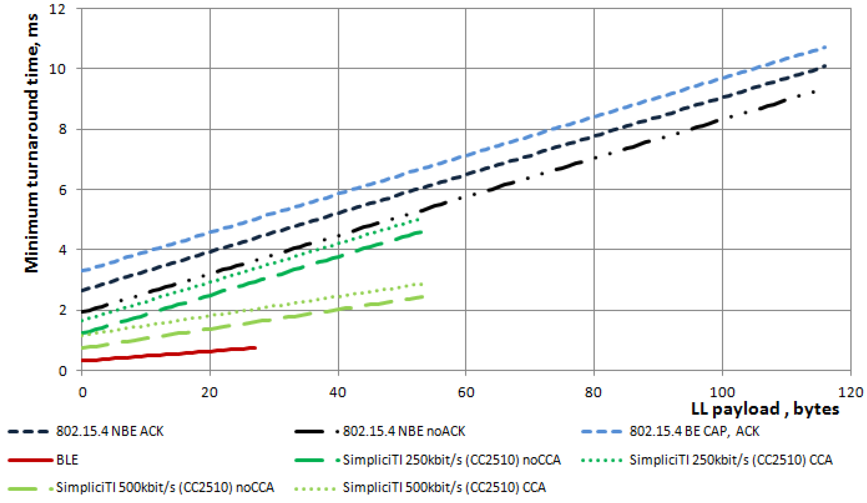
and  are presented in Figure 9. As one can see, BLE is expected to have the lowest turnaround time among the protocols under discussion. This is not surprising, as BLE enables the receiver to send a reply frame immediately after the IFS, which equals
  . SimpliciTI is expected to have a roundtrip time of 0.7 ms to 2.9 ms for the transmissions at and 1.2 ms to 5 ms at
  .The roundtrip time for IEEE 802.15.4 is estimated to range from 1.92 ms to 9.34 ms for unacknowledged and from 2.65 ms to 10.08 ms for acknowledged data transfer, depending on the payload size.


| Stack | Time 1, ms | Consumed energy 1,  | Energy efficiency 1,/byte | |
|---|---|---|---|---|
| Transmission (for BLE - also reception) of a single frame with a 19-byte LL payload: | ||||
| TIMAC, acknowledged 2 | 2.50 | 190 | 10.0 | |
| TIMAC, unacknowledged | 1.66 | 125 | 6.6 | |
| BLE, ADV_IND 3 | 0.73 | 42 | 2.2 | |
| BLE, ADV_NONCONN_IND | 0.50 | 31 | 1.6 | |
| BLE (master node), data frame transmission 4 | 0.66 | 39 | 2.1 | |
| BLE (master node), data frame reception 5 | 0.66 | 36 | 1.9 | |
| SimpliciTI, CCA, 250 kbit/s | 2.46 | 165 | 8.7 | |
| SimpliciTI, no CCA, 250 kbit/s | 2.21 | 148 | 7.8 | |
| SimpliciTI, CCA, 500 kbit/s | 1.76 | 105 | 5.5 | |
| SimpliciTI, no CCA,500 kbit/s | 1.60 | 96 | 5.1 | |
| Transmission (for BLE - also reception) of a single frame with other payloads: | ||||
| TIMAC, acknowledged 2 , 100-byte payload | 5.07 | 406 | 4.1 | |
| TIMAC, unacknowledged, 100-byte payload | 4.30 | 347 | 3.5 | |
| BLE, ADV_IND 3, 31-byte payload | 0.80 | 50 | 1.6 | |
| BLE, ADV_NONCONN_IND, 31-byte payload | 0.60 | 39 | 1.3 | |
| BLE (master node), 27-byte data frame transmission 4 | 0.72 | 44 | 1.6 | |
| BLE (master node), 27-byte data frame reception 5 | 0.72 | 40 | 1.5 | |
| SimpliciTI, 250 kbit/s, CCA, 50-byte payload | 3.5 | 246 | 4.9 | |
| SimpliciTI, 250 kbit/s, no CCA, 50-byte payload | 3.16 | 227 | 4.5 | |
| SimpliciTI, 500 kbit/s, CCA, 50-byte payload | 2.23 | 148 | 3.0 | |
| SimpliciTI, 500 kbit/s, no CCA, 50-byte payload | 2.09 | 141 | 2.8 | |
6. Conclusions
Conflict of Interest
References
- Silicon Laboratories Inc. The evolution of wireless sensor networks. Available online: http://www.silabs.com/Support%20Documents/TechnicalDocs/evolution-of-wireless-sensor-networks.pdf (accessed on 24 June 2013).
- Hatler, M. Industrial wireless sensor networks: Trends and developments. Available online: http://www.isa.org/InTechTemplate.cfm?template=/ContentManagement/ContentDisplay.cfm&ContentID=90824 (accessed on 24 June 2013).
- Bluetooth SIG, Bluetooth Specification Version 4; The Bluetooth Special Interest Group: Kirkland, WA, USA, 2010.
- WTRS Wireless Sensor Network Technology Trends Report; WT062510CNTS; West Technologies Research Solutions: Mountain View, CA, USA, 2010; pp. 1–267.
- Sun, T.; Chen, L.J.; Han, C.C.; Yang, G.; Gerla, M. Measuring Effective Capacity of IEEE 802.15.4 Beaconless Mode. In Proceedings of IEEE Wireless Communications and Networking Conference (WCNC’06), Las Vegas, NV, USA, 3–6 April 2006; pp. 493–498.
- Mikhaylov, K.; Tervonen, J. Analysis and evaluation of the maximum throughput for data streaming over IEEE 802.15.4 wireless networks. J. High Speed Netw. in press.
- Latré, B.; Mil, P.D.; Moerman, I.; Dhoedt, B.; Demeester, P.; Dierdonck, N.V. Throughput and Delay Analysis of Unslotted IEEE 802.15.4. J. Netw. 2006, 1, 20–28. [Google Scholar]
- Choi, J.S.; Zhou, M. Performance Analysis of ZigBee-Based Body Sensor Networks. In Proceedings of IEEE International Conference on Systems Man and Cybernetics (SMC’10), Istanbul, Turkey, 10–13 October 2010; pp. 2427–2433.
- Liang, X.; Balasingham, I. Performance Analysis of the IEEE 802.15.4 Based ECG Monitoring Network. In Proceedings of IASTED Wireless and Optical Communications Conference (WOC’07), Montreal, QC, Canada, 30 May–1 June 2007; pp. 99–104.
- Zhang, Y.; Atac, A.; Liao, L.; Heinen, S. A Low-Power High-Efficiency Demodulator in Bluetooth Low Energy Receiver. In Proceedings of 8th Conference on Ph.D. Research in Microelectronics and Electronics (PRIME’12), Aachen, Germany, 12–15 June 2012; pp. 1–4.
- Masuch, J.; Delgado-Restituto, M. A 190-microWatt Zero-IF GFSK Demodulator with a 4-b Phase-Domain ADC. IEEE J. Solid-St. Circ. 2012, 47, 2796–2806. [Google Scholar] [CrossRef]
- Wong, A.; Dawkins, M.; Devita, G.; Kasparidis, N.; Katsiamis, A.; King, O.; Lauria, F.; Schiff, J.; Burdett, A. A 1 V 5 m A Multimode IEEE 802.15.6 / Bluetooth Low-Energy WBAN Transceiver for Biotelemetry Applications. In Proceedings of IEEE International Solid-State Circuits Conference (ISSCC’12), San Francisco, CA, USA, 19–23 February 2012; pp. 300–302.
- Yu, B.; Xu, L.; Li, Y. Bluetooth Low Energy (BLE) Based Mobile Electrocardiogram Monitoring System. In Proceedings of International Conference on Information and Automation (ICIA’12), Shenyang, China, 6–8 June 2012; pp. 763–767.
- Ali, M.; Albasha, L.; Al-Nashash, H. A Bluetooth Low Energy Implantable Glucose Monitoring System. In Proceedings of 8th European Radar Conference (EuRAD’11), Manchester, UK, 12–14 October 2011; pp. 377–380.
- Jara, A.J.; Fernandez, D.; Lopez, P.; Zamora, M.A.; Ubeda, B.; Skarmeta, A.G. Evaluation of Bluetooth Low Energy Capabilities for Continuous Data Transmission from a Wearable Electrocardiogram. In Proceedings of 6th International Conference on Innovative Mobile and Internet Services in Ubiquitous Computing (IMIS’12), Palermo, Italy, 4–6 July 2012; pp. 912–917.
- Liu, J.; Chen, C.; Ma, Y. Modeling Neighbor Discovery in Bluetooth Low Energy Networks. IEEE Commun. Lett. 2012, 16, 1439–1441. [Google Scholar] [CrossRef]
- Gomez, C.; Oller, J.; Paradells, J. Overview and Evaluation of Bluetooth Low Energy: An Emerging Low-power Wireless Technology. Sensors 2012, 12, 11734–11753. [Google Scholar] [CrossRef]
- Gomez, C.; Demirkol, I.; Paradells, J. Modeling the Maximum Throughput of Bluetooth Low Energy in an Error-Prone Link. IEEE Commun. Lett. 2011, 15, 1187–1189. [Google Scholar] [CrossRef]
- Kamath, S.; Lindh, J. Measuring Bluetooth® Low Energy Power Consumption; AN092S (WRA347a); Texas Instruments, Inc.: Dallas, TX, USA, 2012; pp. 1–24. [Google Scholar]
- Siekkinen, M.; Hiienkari, M.; Nurminen, J.K.; Nieminen, J. How Low Energy is Bluetooth Low Energy? Comparative Measurements with ZigBee / 802.15.4. In Proceedings of IEEE Wireless Communications and Networking Conference Workshops (WCNCW’12), Paris, France, 1 April 2012; pp. 232–237.
- ZigBee Specification; 053474r17; ZigBee Standards Organization: San Ramon, CA, USA, 2008; pp. 1–576.
- Fujii, C.; Seah, W.K.-G. Multi-Tier Probabilistic polling in Wireless Sensor Networks Powered by Energy Harvesting. In Proceedings of 7th International Conference on Intelligent Sensors, Sensor Networks and Information Processing (ISSNIP’11), Adelaide, SA, USA, 6–9 December 2011; pp. 383–388.
- Skrzypczak, L.; Grimaldi, D.; Rak, R. Basic Characteristics of ZigBee and Simpliciti Modules to Use in Measurement Systems. In Proceedings of 19th IMEKO World Congress, Lisbon, Portugal, 6–11 September 2009; pp. 1456–1460.
- Bertarelli, F. Energy Cluster Aggregation in a WSN Based on EZ430-RF2500 T Nodes and SimpliciTI Protocol. In Proceedings of 4th Education and Research Conference (EDERC’10), Nice, France, 1–2 December 2010; pp. 145–149.
- IEEE 802 Working Group, IEEE Standard for Local and Metropolitan Area Networks—Part 15.4: Wireless Medium Access Control (MAC) and Physical Layer (PHY) Specifications for Low-Rate Wireless Personal Area Networks (LR-WPANs); IEEE Std 802.15.4-2003; 2003; Volume 4, pp. 1–670.
- IEEE 802 Working Group, IEEE Standard for Local and Metropolitan Area Networks—Part 15.4: Wireless Medium Access Control (MAC) and Physical Layer (PHY) Specifications for Low Rate Wireless Personal Area Networks (WPANs); IEEE Std 802.15.4-2006; 2006; pp. 1–320.
- IEEE 802 Working Group, IEEE Standard for Local and Metropolitan Area Networks—Part 15.4: Low-Rate Wireless Personal Area Networks (LR-WPANs); IEEE Std 802.15.4-2011, 2011; pp. 1–314.
- Aaberge, T. Low Complexity Antenna Diversity for IEEE 802.15.4 2.4 GHz PHY. M.Sc. Thesis, Norwegian University of Science and Technology, Trondheim, Norway, June 2009. [Google Scholar]
- Texas Instruments SimpliciTITM - RF Made Easy. Available online: http://www.ti.com/simpliciti/ (accessed on 14 June 2013).
- Nakutis, Z. Embedded Systems Power Consumption Measurement Methods Overview. MATAVIMAI 2009, 2, 29–35. [Google Scholar]
- Mikhaylov, K.; Tervonen, J. Optimization of Microcontroller Hardware Parameters for Wireless Sensor Nnetwork Node Power Consumption and Lifetime Improvement. In Proceedings of 2nd International Congress on Ultra Modern Telecommunications and Control Systems (ICUMT’10), Moscow, Russia, 18–20 October 2010; pp. 1150–1156.
- Mikhaylov, K.; Tervonen, J. Evaluation of Power Efficiency for Digital Serial Interfaces of Microcontrollers. In Proceedings of 5th International Conference on New Technologies, Mobility and Security (NTMS), Istanbul, Turkey, 7–10 May 2012; pp. 1–5.
- Texas Instruments, Low-Power SoC (System-on-Chip) with MCU, Memory, 2.4 GHz RF Transceiver, and USB Controller, 2013; 236.
- Texas Instruments, 802.15.4 MAC Application Programming Interface, SWRA192. 2009; 58.
- Isomaki, M.; Nieminen, J.; Gomez, C.; Shelby, Z.; Savolainen, T.; Patil, B. Transmission of IPv6 Packets over BLUETOOTH Low Energy. Available online: http://tools.ietf.org/html/draft-ietf-6lowpan-btle-12#section-2.4 (accessed on 1 August 2013).
- Wang, H.; Xi, M.; Liu, J.; Chen, C. Transmitting IPv6 Packets over Bluetooth Low Energy Based on BlueZ. In Proceedings of 15th International Conference on Advanced Communication Technology (ICACT’13), PyeongChang, Korea, 27–30 January 2013; pp. 72–77.
- Deering, S.E.; Hinden, R. Internet Protocol, Version 6 (IPv6) Specification. Available online: http://tools.ietf.org/html/rfc2460 (accessed on 1 August 2013).
- WirelessHART; IEC 62591:2010(E); International Electrotechnical Comission: Austin, TX, USA, 2010.
- Wireless Systems for Industrial Automation: Process Control and Related Applications; ANSI/ISA-100.11a-2011; International Society of Automation: Research Triangle Park, NC, USA, 2011; pp. 1–792.
- Kushalnagar, N.; Montenegro, G.; Culler, D.E.; Hui, J.W. Transmission of IPv6 Packets over IEEE 802.15.4 Networks. Available online: http://tools.ietf.org/html/rfc4944 (accessed on 2 August 2013).
© 2013 by the authors; licensee MDPI, Basel, Switzerland. This article is an open access article distributed under the terms and conditions of the Creative Commons Attribution license (http://creativecommons.org/licenses/by/3.0/).
Share and Cite
Mikhaylov, K.; Plevritakis, N.; Tervonen, J. Performance Analysis and Comparison of Bluetooth Low Energy with IEEE 802.15.4 and SimpliciTI. J. Sens. Actuator Netw. 2013, 2, 589-613. https://doi.org/10.3390/jsan2030589
Mikhaylov K, Plevritakis N, Tervonen J. Performance Analysis and Comparison of Bluetooth Low Energy with IEEE 802.15.4 and SimpliciTI. Journal of Sensor and Actuator Networks. 2013; 2(3):589-613. https://doi.org/10.3390/jsan2030589
Chicago/Turabian StyleMikhaylov, Konstantin, Nikolaos Plevritakis, and Jouni Tervonen. 2013. "Performance Analysis and Comparison of Bluetooth Low Energy with IEEE 802.15.4 and SimpliciTI" Journal of Sensor and Actuator Networks 2, no. 3: 589-613. https://doi.org/10.3390/jsan2030589