1. Introduction
Wireless sensor devices are physically small electronic devices equipped with the appropriate sensors, a micro-controller, a limited amount of memory and a radio transceiver for communicating with other devices. They are designed to be inexpensive, so that they can be deployed in large numbers. A small battery provides the necessary power. They communicate using radio and messages may be relayed over several nodes to the final destination. They can be deployed for monitoring in all kinds of applications, such as building structures, seismic activities, soil condition, etc. Their wireless communication also makes them useful for mobile applications, such as for wild-life monitoring, vehicular networks, bodily health monitoring and in difficult to access areas. They may be installed in fixed, mobile or ad hoc applications.
One consequence of their open wireless communications is that an adversary can easily eavesdrop on messages and also transmit malicious messages into the network. This vulnerability may be a setback to their widespread acceptance, especially in sensitive applications. It is therefore necessary to be able to protect the communications using proven cryptographic techniques. To do this requires the communicating nodes to share secret keys.
The physical deployment environment allows the adversary to physically take control of nodes and extract secret keys from the node’s memory. Due to cost, sensor nodes do not have tamper proof mechanisms. To minimise the impact of compromised nodes, the keys should be shared with as few nodes as possible, preferably between pairs only. In large ad hoc mobile networks, there are a large number of pairwise keys, and nodes would need a large amount of memory to store them. A better solution is to use a key agreement scheme where pairs of nodes would compute their pairwise keys after exchanging some information over the insecure channel. Such schemes, such as those by Diffie-Hellman (DH), by Rivest, Shamir and Adleman (RSA) and by El-Gamal, are already widely used in computer networks. These use public key cryptographic (PKC) algorithms involving complex mathematical operations on large integers and require substantial computational, memory and energy resources that are not readily available in sensor nodes.
Symmetric cryptographic key agreement schemes are more efficient, but they generally have limitations, such as large memory requirements, limited key sizes and scalability. This paper, an extension of our previous works in [
1,
2,
3], presents a symmetric key scheme, which retains the advantages of the symmetric key scheme and also is able to overcome these limitations.
1.1. This Contribution
Blom’s key agreement scheme [
4,
5] is fast, efficient and has mutual authentication features, making it attractive for low-resource sensor devices in
ad hoc mobile networks. Unfortunately, as nodes can be captured and have their keys stolen, Blom’s scheme can be completely broken once a certain number of nodes are compromised. Our scheme is able to break free of this limitation. The main idea is to use multiple master keys and public keys in permutations to obtain multiple private keys for each node. The computations are over a small prime field, and the private keys are stored in a random order. As a result, the private-public-master-key association (PPMka) information is lost. Without the PPMka, captured private keys are unusable for breaking the scheme. We obtained analytical results to compute the probabilities of retrieving the PPMka and showed that, with suitable keying parameters, the adversary will need to capture a very large number of nodes or expend an infeasible amount of resources to obtain the PPMka. This makes our scheme useful as the cryptographic primitive for large sensor networks.
1.2. Structure of Paper
The paper is structured as follows: In
Section 2, we describe some related works using Blom’s key agreement scheme. In
Section 3, we describe the basic concepts and features of our scheme. In
Section 4, we define our security and adversary models and analyse possible attacks on the scheme. We show that without the PPMka information, the scheme cannot be attacked. In
Section 5, we analyse how the PPMka information may be discovered and compute the probabilities of successful attacks. These are compared to those obtained using computer simulated attacks on the scheme. In
Section 6, we discuss the performance of the scheme in terms of memory requirements, computation times and scalability. Some keying and performance parameters are given for practical implementations. In
Section 7, we discuss the strengths and limitations of the scheme, and we give our conclusion in
Section 8.
Notations and Terms Used
ID the public key ID, an integer
K private key, a secret (1 × m) row vector unique to the node
M master key, an (m × m) secret symmetric matrix belonging to the trusted authority (TA)
N the number of master keys
R pairwise key set, the set of integers used to form the pairwise key
S private key set, the set of Nη private keys
V public key, an (m × 1) column vector unique to the node and available to everyone
m the size of the master key matrix
nc the number of captured or compromised nodes
η the number of public keys assigned to each node
p the prime modulus for all operations, except public keys
q the prime modulus for public key operations only
s the public key seed, an integer ∈ [0; q − 1]
2. Related Works
Blom’s scheme [
5] is unconditionally secure in that, if not more than a certain number of nodes are compromised, the scheme cannot be broken, as there is simply insufficient information [
6]. On the other hand, if enough nodes are compromised, the attacker would be able derive the master key and completely break the scheme. Blundo’s polynomial conference key distribution scheme [
7] with bivariate symmetric polynomials is equivalent to Blom’s scheme. For sufficiently large pairwise keys and application in a large networks, each node would require a substantial amount of memory to store its private key.
A number of attempts have been made on either Blom’s or Blundo’s scheme to enhance node capture resilience by using multiple key spaces, so that the attacker has less chance of obtaining all of the nodes in the same key space. For example, the scheme in [
8] used multiple key spaces and incorporated a probabilistic method similar to Eschenauer and Gilgor’s [
9], such that pairs of nodes must discover their shared key space to compute their pairwise key. To achieve full connectivity, if a pair of nodes do not share a key space, secured intermediary nodes are used to establish their pairwise key. An equivalent scheme in [
10] was independently discovered at the same time. The pairwise key sizes were 64 bits. In these schemes, resilience against node capture is enhanced since the probability of capturing enough nodes in the same key space is reduced. A similar idea using multiple key spaces was proposed in [
11], but in this case, the nodes are connected in a complete bipartite graph. In [
12], only the cluster heads implemented Blom’s scheme, thus allowing the overall network size to be larger than the number of cluster heads, which must be within the capture threshold to be secure.
A different idea in [
13] based on the bivariate polynomial with multiple-key spaces added random perturbations to the polynomials, so that captured nodes cannot be used to break the scheme. They were able to compute 80-bit pairwise keys in about 0.13 s, requiring about 15 KB ROM and 0.33 KB RAM. In a similar approach, the work in [
14] used random perturbations, which are hashed with the pairwise key obtained using Blom’s scheme. After establishing the pairwise key, the private keys are erased to prevent the adversary from obtaining them. A newly deployed node would not be able to implement Blom’s scheme to connect to an already secured node. Instead, it is deployed with an ID and a secret key shared with the base station. To authenticate a new node, the secured node would contact the BSto obtain the secret key shared with the node. Another implementation in [
15] also uses random perturbations. Here, small random perturbations are added to the private keys to break the direct connection to the master key, making it more difficult to break. The pairwise keys computed are identical after the effect of the small random perturbations are removed.
A scheme in which the private vectors of the nodes can be updated was proposed in [
16]. In this scheme, the modified Blom’s scheme used hashed values of the prime seeds, and similarly, nodes have private vectors, which are hashes of the original private vectors. Their scheme limits the node capture to less than the capture threshold.
3. The BYka Scheme
3.1. Blom’s Scheme
Blom’s scheme [
5], on which our scheme is based, is briefly described as follows. An entity, called the trusted authority (TA) generates for itself a master key
, which is a random
symmetric matrix over the prime field
. It assigns a node a public key
, which is an
column vector in
. The TA computes and stores in the node its private key
(mod
p). To obtain their pairwise key, a pair of nodes, e.g., nodes
A and
B exchange their public keys and compute (mod
p),
The quantity is a scalar, and transposing . Since is symmetric, the two keys and are identical.
3.2. The BYka Scheme
Our multiple-key Blom’s scheme [
1,
2], now called the Blom–Yang key agreement (BYka) scheme, uses the Blom’s scheme as the cryptographic primitive, but with multiple master keys and public keys used in permutations in a single key space.
3.3. Setup
The TA selects the keying parameters: the number of secret master keys N, the size m, the number of public keys in each node η, the prime modulus for key computations p and the prime modulus for public key computations q. For example, and , to obtain pairwise keys of 128 bits for a network of about 10,000 nodes.
The TA generates N master keys , over the prime field . These are symmetric matrices.
3.3.1. Public Key Set and IDs
The TA assigns to each node η unique public keys, called the public key set, each one an column vector of the Vandermonde matrix over the field . As the elements of a column in the Vandermonde matrix are for , where s is called the “seed”, the node needs only be assigned η seeds . The seeds are consecutive, and the smallest seed s is a multiple of η. In this way, no two nodes share a common seed. The node’s public key set can be succinctly represented by the smallest seed s, which also serves as its public key , e.g., using , a node A with public key has public key seeds . Given a node’s public key , anyone knowing q can generate its public key set as follows,
When pairs of nodes exchange their public keys, they only need to transmit their IDs consisting of a few bits, e.g., 16 bits. This is an important feature, saving time and energy for radio transmissions.
3.3.2. Private Key Set,
The TA computes the private keys for each node using all the permutations of their η public keys with its N master keys to obtain the node’s “private key set” , where , called the private key, is a row vector, computed as follows,
PPMka
The private key is computed from the public key and the master key . We call the relationship of a private key with the public key and master key used to compute it the “private-public-master-key association” (PPMka). The TA transfers the private key set to the node using a secure connection and stores them in random order. Alternatively, the private key set can be first shuffled before transferring to the node. If a node is compromised and the private keys obtained, the adversary cannot tell from the storage location which public key and master key was used to compute it.
3.3.3. Key Aliasing
The number of public key seeds must be large enough to accommodate the network size. To do this, the public key operations are over a large field
, for example,
catering to about 10,000 nodes, but it can be much larger. As the private key operations are over a small field
, it is possible for multiple public keys to map to the same private key, a phenomenon we call “key aliasing”, described as follows. Consider the private key
, where
is the seed for
. Denoting the elements of
as
and using Equation (
1), the
element of
is,
For two nodes, say A and B, if any of their public key seeds are congruent, e.g., (mod p), and for all , the elements and are smaller than q (the elements in the public key vectors do not “wrap round” q), then we have (mod p) for all i. As a result, their private keys associated with the same master key are identical since,
To prevent key aliasing, a seed is chosen, such that at least one vector element exceeds q, and the residue r (mod q) is different from (mod p) and is not zero. The requirements of a seed are then,
The TA installs into each node their “keying material” comprising the global keying parameters , the node’s individual public key ID and private key set . All of these are static and can be stored in the ROM or flash memory.
3.4. Pairwise Key Computation
After deployment, any pair of nodes can compute their pairwise key after exchanging their IDs. For example, nodes
A and
B have obtained each other’s IDs. Each node generates their counterpart’s public keys using Equation (
1) and, then, using all of the permutations with its own private key set, computes (mod
p) the set
R, called the “pairwise key set”, as follows,
Transposing each element in , we have,
Since is symmetric and are merely independent counters, the sets and each contain identical numbers , though not in the same order. These numbers are used by both nodes to form their pairwise key .
Pairwise Key
The pairwise key can be constructed from the pairwise key set R using several methods. In one method, the number of occurrences of the integers in R are counted and used as the input to a hash function to output the pairwise key. In another method, the numbers in R are sorted and concatenated into a large key. It is also possible to increment all elements in R by one to make them all non-zero and then multiply them together (mod ) to obtain the pairwise key, where is a large prime number of the desired key size. Once the nodes have obtained their identical pairwise key, they can use it for encrypting messages or to transport a randomly generated session key for subsequent communications.
4. Security of the BYka Scheme
4.1. Security Model
This section defines the components of the system, the adversary and its capabilities and the meaning of system breakdown.
4.1.1. System
The system comprises nodes belonging to one administrative unit under the same TA. It is assumed that TA has access to a cryptographically secure random number generator. The master keys are assumed secure and cannot be stolen. If need be, they can be deleted after generating all of the possible public and private key sets. The nodes have access to secure cryptographic algorithms, such as AESencryption and hash algorithms.
4.1.2. Adversary
The adversary is a very powerful agent with powerful computing resources. It is able to move about freely in the deployment space to monitor transmissions, replay messages and insert its own fabricated messages. It is also able to physically capture nodes and extract all the keying material, including the public key IDs, the private key sets and the keying parameters from ROM and RAM memory.
4.1.3. System Breakdown
The scheme is considered broken if the adversary is able to, by monitoring transmissions or using the keys from captured nodes,
- (1)
obtain the pairwise keys of any other pairs of uncompromised nodes, or
- (2)
fabricate new valid public and private keys, or
- (3)
compute the master keys of the TA.
Identity theft attacks, where the adversary clones a node by fabricating a new node with the identical keys from the captured node, though a very serious threat, is beyond the scope of this paper.
4.1.4. Vulnerabilities
The vulnerabilities of the BYka scheme are broken down and analysed in the three main parts:
- (1)
Strength of the keys against brute force attacks
- (2)
Security of the underlying Blom’s scheme, as it applies to the BYka scheme
- (3)
Resilience against node capture
4.2. Strength of Keys against Brute Force Attacks
The master keys and private keys are random and large. For example, with values of , , and , there are possible master keys and private keys. A brute force attack is not feasible.
Pairwise Key
One limitation in the original Blom’s scheme is that the pairwise key is only the same size as the data size of the master key elements. In our BYka scheme, the pairwise key size can be up to integers .
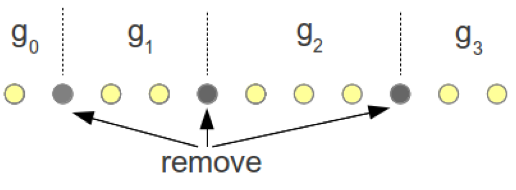
The BYka scheme can be viewed as a mechanism for two nodes to derive a common secret pairwise key set R consisting of integers from which to construct their pairwise key. The number of possible keys, the “key space”, is limited by the number of possible combinations of the integers. To determine the key space size, we consider the following partitioning problem.
Given a row of
items, we wish to partition them into
p groups. This is illustrated in
Figure 1 for the case of partitioning eight items into four groups. To create the partitions, we first insert
items into the row, so that there are now
items. If any
items are now removed,
gaps would be created, separating the remaining items into
p groups as desired. Let group
contain the integer zero,
contain one,
contain two,
etc. The total number of integers is always
. The number of ways to remove
items from
gives the key space size as follows,
Table 1 shows the key space sizes for various keying parameters in bits. It can be seen that the key spaces of 64 bits and larger are possible.
Figure 1.
Partitioning eight items into four groups.
Figure 1.
Partitioning eight items into four groups.
Table 1.
Key space in bits.
Table 1.
Key space in bits.
| η | N | Values of p |
| 13 | 17 | 19 | 23 | 31 |
| 6 | 6 | 64 | 80 | 88 | 102 | 127 |
| 7 | 67 | 84 | 92 | 106 | 134 |
| 8 | 69 | 87 | 95 | 111 | 139 |
| 7 | 6 | 69 | 87 | 95 | 111 | 140 |
| 7 | 72 | 91 | 99 | 116 | 146 |
| 8 | 74 | 94 | 103 | 120 | 152 |
| 8 | 6 | 74 | 93 | 102 | 119 | 151 |
| 7 | 77 | 97 | 106 | 124 | 157 |
| 8 | 79 | 100 | 109 | 128 | 163 |
4.3. Security of the Underlying Blom’s Scheme
Blom’s scheme is vulnerable to the Sybil attack, and the master key can be derived if enough nodes are captured. We now examine how this can be done and then analyse how our BYka scheme would fare.
4.3.1. Sybil Attacks
In this attack, the attacker would fabricate new public and private keys by combining captured keys and use them to masquerade legitimate nodes. Consider that
n nodes and their public and private keys have been obtained. The attacker can fabricate a new public key
by linear combination of captured public keys as follow:
The corresponding private key
would also be a similar linear combination of the captured private keys,
By choosing various combinations of , the attacker is able to fabricate any public key and the corresponding private key at will.
Mitigation
To defeat this attack, three conditions must be met:
- (1)
the public keys must conform to a prescribed structure,
- (2)
the public keys are linearly independent, and
- (3)
no more than nodes are captured, i.e., .
The first condition ensures that a key formed from arbitrary linear combinations of captured keys would not be accepted. If all of the public keys are of a prescribed structure, such as those of the column of the Vandermonde matrix, arbitrary public keys would simply be discarded.
If all of the public key vectors are linearly independent and
, then by definition, the solution of Equation (
7) is trivial,
i.e.,
. On the other hand, if
, then, as there are at most
m linearly independent
vectors, any
m public keys can be combined to obtain a non-trivial solution in Equation (
7) and obtain the corresponding private key using Equation (
8).
4.3.2. Attacking the Master Key
Consider that
m nodes have been captured and all of the public keys are linearly independent. The attacker would be able to construct a system of
m linear equations from each private key using the relationship,
, which, after transposing, can be written as
where
. Combining these from the
m captured nodes, we have,
From linear algebra, the matrix is invertible if, and only if, the determinant . Since the column vectors in are linearly independent (for example, the Vandermonde matrix), then is non-singular with a non-zero determinant. The elements of the master key can be obtained, for example using the Gaussian elimination method.
Capture Threshold λ
The above shows the main limitation of Blom’s scheme. If the number of captured nodes reaches m, called the “capture threshold”, the entire scheme can be broken. Bloms’s scheme is said to be secure if the number of nodes deployed is <m. Then, even if all of the nodes are captured, there is no determinate solution for , and it is unconditionally secure.
To implement a Blom’s scheme that is secure, a large m would be required and, together with the requirement for large pairwise key sizes, the nodes would require a large memory to store the private keys. This places a limit on Blom’s scheme.
4.3.3. Immunity to MITM Attacks and Mutual Authentication
In the man-in-the-middle (MITM) attack, an adversary node E interposes itself between two nodes A and B. It posses as A to B and, similarly, as B to A. If this is successful, it acts as an intermediary between A and B, reading and modifying messages before forwarding them. In Blom’s scheme, if the attacker E forwards its own to node A to impersonate node B, node A would compute the pairwise key . Node E cannot compute , as it does not have the private key for . If E forwards to node A and to node B, both nodes A and B can compute their pairwise key , which cannot be obtained by node E. Messages encrypted between nodes A and B cannot be read by E. Blom’s scheme is immune to MITM attacks, as both nodes must use keying material from the TA to compute their pairwise key. In this way, the scheme is mutually authenticating.
4.3.4. Implications for the BYka Scheme
The BYka scheme inherits the mutual authentication and immunity to the MITM attacks as in Blom’s scheme. In addition, it would also appear to inherit the capture threshold limitation. In fact, the BYka scheme’s capture threshold is lower at , since each node carries private keys. However, the capture threshold is not applicable, since, to use the captured private keys, the attacker needs to associate each private key with the public key and master key used to compute it, i.e., discover the PPMka. In the original Blom’s scheme with only one key, the PPMka is obvious.
4.4. Resilience against Sybil Attacks
The Sybil attack cannot be mounted as in Blom’s scheme. Consider that
m private keys
and the corresponding public keys
associated with one of the master keys
have been obtained. The attacker chooses a public key
seed
and constructs the public key
as a Vandermonde column vector, such that,
The coefficients
can be obtained and used to construct the private key associated with
and
,
Here,
is the private key associated with the master key
and public key
. The difficulty is identifying which of the
private keys in the node is this particular one, and similarly for
,
etc. Each private key is a row vector with elements, which are sums and products of random numbers, and is indistinguishable from the others. The order of storage in memory is also random and unrelated to the order in which they were computed. An adversary cannot derive any information about the private-public-master-key associations (PPMka) from examining the keys or its storage location.
If the PPMka information is not available, the adversary will need to try all of the possible PPMka as follows. From each node, there are
ways to select the
η private keys associated with
and the public keys
. To select all of the private keys in the
captured nodes associated with
and the corresponding public keys for use in Equation (
11), we have
possible ways, given by,
To complete the Sybil attack, all of the public and private keys are similarly constructed for each of the master keys and used together. The total number of possible solutions for all of the PPMka’s is,
Table 2.
Number of Solutions Φ.
Table 2.
Number of Solutions Φ.
| η | N | Master Key Size m |
| 12 | 16 | 24 | 32 |
| 6 | 6 | | | | |
| 7 | | | | |
| 8 | | | | |
| 7 | 6 | | | | |
| 7 | | | | |
| 8 | | | | |
| 8 | 6 | | | | |
| 7 | | | | |
| 8 | | | | |
As an example, with
and
,
possible solutions. Hence, without knowing the PPMka, the Sybil attack requires an unfeasibly large number of trials.
Table 2 gives the possible number of solutions for various keying parameters.
4.5. Brute Force Attack on the Master Keys
Similarly, to solve for all of the master keys using the captured private keys without knowing the PPMka information, the number of possible sets of
linear equations is also given in Equation (
12). Each attempt involves constructing the
system of linear equations, solving them using, say, the Gaussian elimination method and testing each solution to see if it can successfully compute a captured node’s private key using one of its public keys. The possible number of solutions is also given in
Table 2.
Hence, due to the unknown PPMka in the BYka scheme, there is only a probabilistic chance of breaking the scheme, even if sufficient captured keys are available. With suitable keying parameters, the chance can be made so small, that the scheme cannot be feasibly broken. However, the scheme can be broken if the PPMka can be discovered. We show next how discovering the PPMka can be made very difficult by using key operations over a small prime field .
5. Attacks to Discover the PPMka
5.1. Pairing Attack
If the keys from a pair of captured nodes are used to compute their pairwise key set, the identical numbers in the key set can expose the related public and master keys. This is called the “pairing attack”. For example, using nodes
A and
B, their pairwise key sets
and
will contain
identical numbers. This is illustrated in
Figure 2 showing only one of the matching numbers in
and
. The identical numbers
reveal that private keys
and
are both associated with the same master key, say
, and also reveal the PPMka:
and
. If all of the
numbers are unique, then it is easy to discover all of the PPMka. However, since there are
numbers in
and
p is a small prime, there will be ambiguities. For example, with
,
and
, there are 252 numbers, each one
.
Figure 2.
Pairing attack showing one of the matching numbers.
Figure 2.
Pairing attack showing one of the matching numbers.
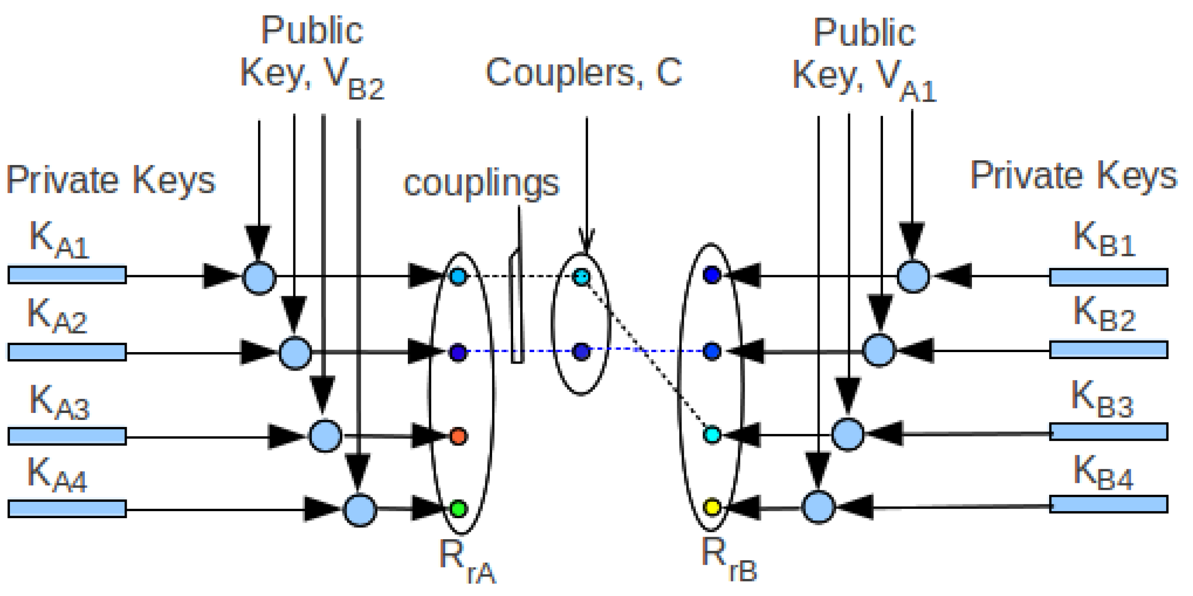
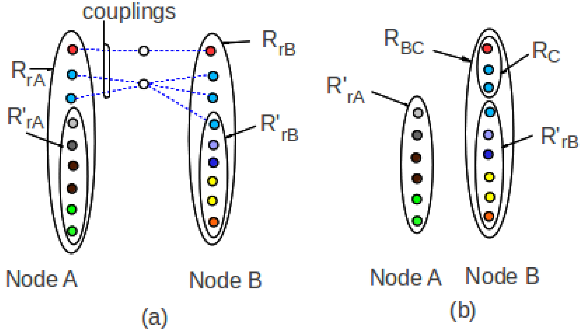
A more efficient pairing attack is to use only one of the public keys to compute the partial key sets
. The number of elements in the partial key set is now reduced to
. This is illustrated in
Figure 3 for the simple case where
. Here, as
, both must be associated with the same master key say,
. Hence,
and
.
If all of the numbers in the partial key sets are unique, the above attack would be successful. However, if they are not all unique, we say that there are “collisions” that give rise to ambiguities, since more than one PPMka is possible for the affected private key.
Figure 3.
Pairing attack having unique couplers, for the case .
Figure 3.
Pairing attack having unique couplers, for the case .
5.1.1. Couplers and Couplings
Each pairing attack, e.g.,
Figure 3, should produce exactly
N identical numbers in sets
and
if all of the numbers are unique. The set
C contains the distinct identical numbers called “couplers”. The links connecting the couplers to the numbers in
and
are called “couplings”. The number of couplings, denoted as
, is ≥ number of couplers.
In the ideal case where there is no collision, there would be exactly couplings on each side of C, each one linking the private key to the associated master key and public key, exposing the PPMka. In this way, by successively pairing an exposed node with other nodes, all of the PPMka can be obtained. However, if the couplers are not unique, then the associated master key is ambiguous for the affected private key.
The probability of having only unique numbers in , hence exactly N couplers in a set of numbers, is . To make this attack more difficult, can be made very small by choosing a small value of p and somewhat larger values of N and η. For example, with , , . For , then , since .
5.1.2. Pairing Attack Strategies
We consider two extreme approaches to discovering the PPMka information to show the difficulty and effort required. First, we consider the “unlimited capture” case where the attacker is able to pick and choose any of the nodes for pairing, and second, the “limited capture” case, where the attacker has obtained only a sufficient number of captured nodes.
5.2. Unlimited Capture
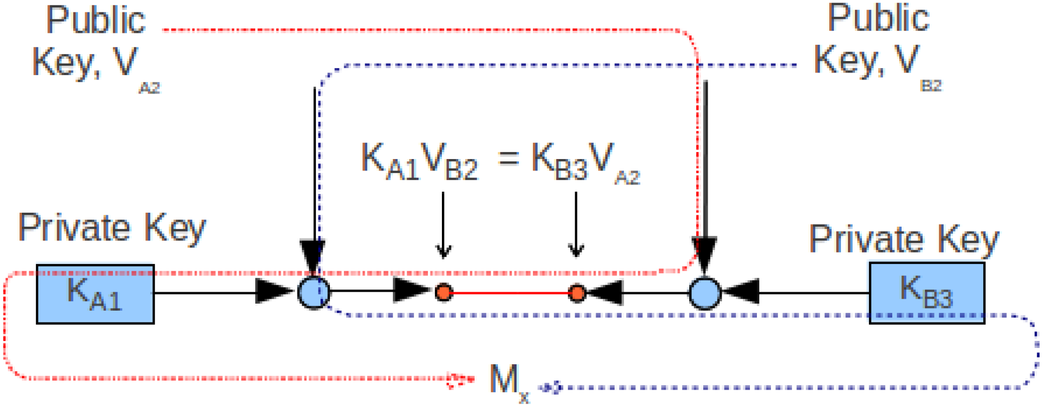
5.2.1. Traitor Node
The attack would be easier if it is possible to find one node in which all of the
N private keys associated with one public key, say
, is known. This set of private keys can be used to reveal the PPMka of other private keys. We call this the “traitor node”. For example, in
Figure 4, the traitor node
T is available, whose keys
and
are known to be associated with
and
, respectively. If the node
B is paired with it and if the number of couplings in
is
N, they distinctly link the connected private keys in
B to the exposed private keys in
T revealing the PPMka,
i.e.,
and
must be associated with
and
, respectively, and both associated with
.
Figure 4.
The traitor node can be used to attack private-public-master-key associations (PPMka).
Figure 4.
The traitor node can be used to attack private-public-master-key associations (PPMka).
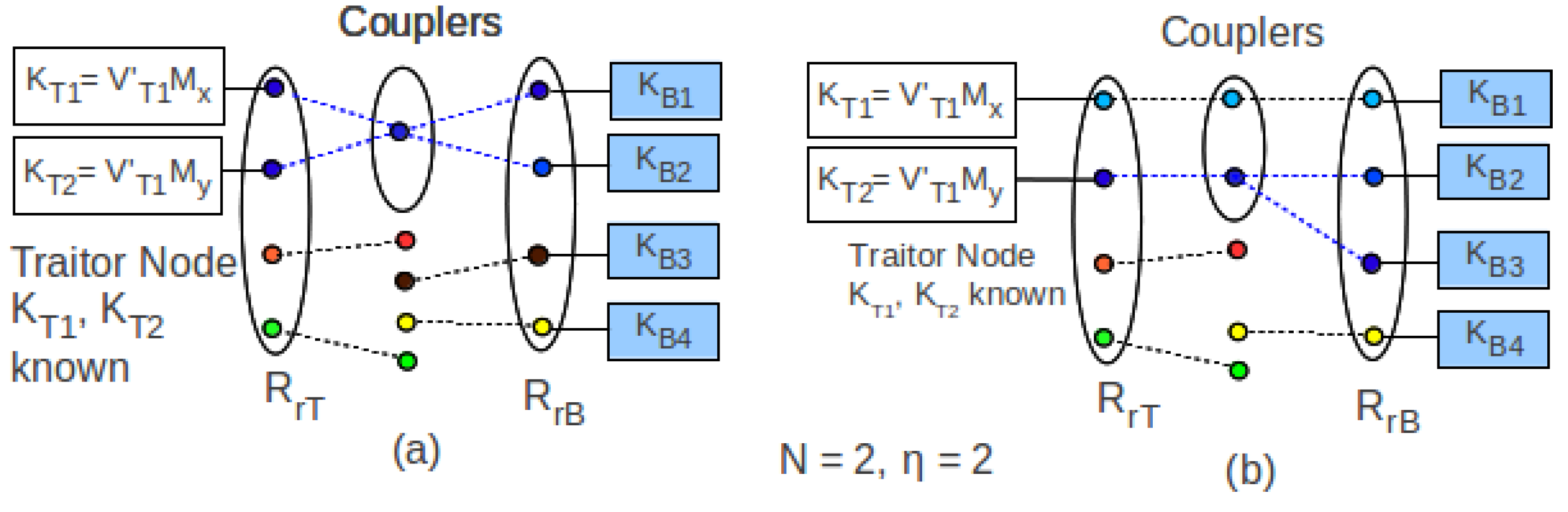
This is not so straightforward if the number of couplers in
is
, as in
Figure 5. In
Figure 5a, the partial key set
obtained using public key
has less couplers than
N,
i.e., only one coupler instead of two. While the private keys
and
can be associated with
, their associations with the master keys are ambiguous. Furthermore, in
Figure 5b,
has more than
N couplers,
i.e., three instead of two. Now, it is not clear whether
or
is associated with
and
. Hence, when a node is paired with the traitor and has exactly
N couplers, the PPMka of the connected private keys will be revealed. Finding a traitor node is thus the first step to discovering the PPMka information.
Figure 5.
The traitor node cannot be used to attack the PPMka.
Figure 5.
The traitor node cannot be used to attack the PPMka.
5.2.2. Probability of Finding a Traitor Node
A traitor node
T is found if, in a pairing, the number of couplings it has is
; for example, in
Figure 3, both nodes can be used as the traitor node. If
, there are ambiguities, since there are >1 possible associations between the
private keys and the
N master keys.
To calculate the probability of finding a traitor node, we consider the following problem. In
Figure 6a, the pairing attack produces partial key sets
and
. We remove the couplers from
, to form the set,
, leaving the reduced partial key set
; see
Figure 6b. A traitor node is found if the reduced set
is disjoint with
or
is disjoint with
. Additionally, sets
,
and
can all be disjoint. The probability of these occurrences can be found by counting the number of arrangements for the above cases. Let
,
and
be the number of elements in sets
,
and
, respectively. Here,
,
.
Figure 6.
Finding the traitor node.
Figure 6.
Finding the traitor node.
Two Disjoint Sets
Consider the case where the two sets and are disjoint. The set can have one number repeated times, e.g., ,, etc., or two different numbers in various arrangements, e.g., , , etc., or three different numbers, e.g., , , and so on. For each case, the remaining numbers can be used in the set .
Before proceeding, first consider the number of ways
of arranging
numbers, such that each arrangement uses all of the given
r numbers. For example, in arranging four numbers using all three numbers
, arrangements like
and
would be included, but excluded those arrangements using only one or two of the numbers, such as
and
,
etc. Let the number of arrangements be
. It can be shown that,
The total number of arrangements where
is disjoint with
is then,
All Disjoints Sets
It is also possible that the sets
,
and
are all disjoint. The number of possible arrangements
can be similarly shown to be given by;
where
and
are obtained as in Equation (
13). The set
also includes the cases where
and
are disjoint. Overall, the total number of arrangements of either
being disjoint with
, or
being disjoint with
, or all three sets
,
and
disjoint is,
The probability of finding a traitor node is then,
With suitable keying parameters, the probability of finding a traitor node can be made very small. For example, with and , the probability is only .
5.2.3. Expected Node Capture to Find a Traitor Node
We assume the attacker is able to capture any number of nodes, and as each new node is captured, it is paired with each of the previous ones to find a traitor. Since the probability of finding a traitor node is , the expected number of attempts to find one is .
Each node has
η public keys to try, so each pair of nodes allows
attempts. If the number of nodes captured is
, the number of pairs that can be formed is
, giving a total of
pairing attempts. To find a traitor node, we have,
The expected number of captured nodes nc required to find a traitor node is shown in
Table 3 for some keying parameters. It can be seen that for these cases, thousands of nodes need to be captured, just to find one traitor node.
Table 3.
Capture sizes to find a traitor node.
Table 3.
Capture sizes to find a traitor node.
| η | N | Prime Modulus, p |
| 13 | 17 | 19 | 23 | 31 |
| 6 | 6 | | | | | |
| 7 | | | | | |
| 8 | | | | | |
| 7 | 6 | | | | | |
| 7 | | | | | |
| 8 | | | | | |
| 8 | 6 | | | | | |
| 7 | | | | | |
| 8 | | | | | |
Finding a traitor node does not break the scheme, but only slightly improves the chances of finding the PPMka in subsequent pairings.
5.3. Limited Capture Pairing Attack
In this case, the attacker, having obtained (sufficient) nodes, would try to obtain the master keys by solving the system of equations formed from the captured keys. By pairing the nodes using only one of each other’s public keys, the set of reduced key sets of numbers are obtained.
In the ideal case, the pairing would produce exactly N couplings in each node, one for each master key and all related to the same public key. However, if the number of couplings is , then there are possible ways to associate the related private keys to the public key and one of the master keys, say . Using all of the η public keys one at a time, the number of possible associations, hence the number of sets of equations, obtained from one node is related to the public keys and the master key . Using all of the captured nodes, the equations required are obtained and solved for the master . The number of sets of equations possible to solve for is .
After obtaining the first master key, the exposed private key is removed, leaving
keys to choose from to solve for the next master key. In total, to solve for all of the master keys, the possible number of sets of equations,
i.e., the number of iterations required, is:
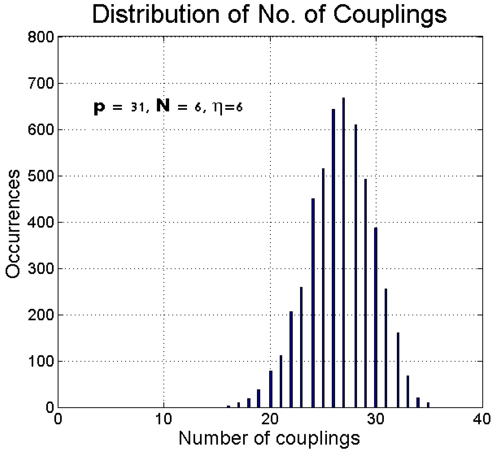
Binomial Distribution Approximation
Figure 7 shows the distribution of the number of couplings in the pairing attacks for the case
,
. Other cases exhibit the same distribution, and they suggest that the distribution of the number of couplings
x can be approximated by the binomial distribution,
Figure 7.
Distribution of the number of couplings for .
Figure 7.
Distribution of the number of couplings for .
Table 4.
Values of . Probable number of master key solutions, Φ.
Table 4.
Values of . Probable number of master key solutions, Φ.
| η | N | | | |
| 13 | 17 | 31 | 13 | 17 | 31 | 13 | 17 | 31 |
| 6 | 6 | | | | | | | | | |
| 7 | | | | | | | | | |
| 8 | | | | | | | | | |
| 7 | 6 | | | | | | | | | |
| 7 | | | | | | | | | |
| 8 | | | | | | | | | |
| 8 | 6 | | | | | | | | | |
| 7 | | | | | | | | | |
| 8 | | | | | | | | | |
From Equation (
17), we can compute the probability of
N couplings,
i.e.,
. After solving for
, we obtain the mean
. Then, using the expected number of couplings in a pairing as
, the number of iterations required is,
Table 4 gives the probable number of master keys solutions
for various keying parameters.
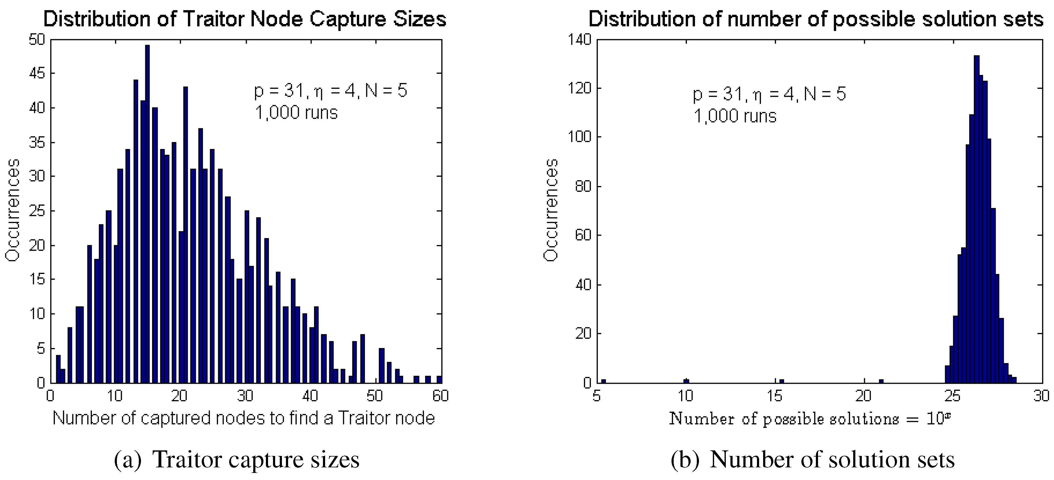
5.4. Experimental Results of Pairing Attacks
A computer programme was used to implement the pairing attacks to determine the traitor capture sizes and the number of possible master key solutions Φ. The programme first generates the master keys. It then randomly creates new nodes with unique IDs to simulate captured nodes. As each node is created, it is paired with each of the previously “captured” nodes until a traitor node is found. At the same time, the number of couplings is accumulated for the first nodes. This is the probable number of couplings in the limited captured case. When a traitor node is found, a new implementation is made using a new set of master keys and this is repeated for 1000 runs.
These are real attacks on real systems as the public and private keys can be implemented in real sensor nodes. They are “simulated” attacks in the sense that capturing the nodes and extracting the keys are done in the computer programme. This greatly accelerates the attacks. Real-life attacks would require much more effort and time.
Due to the large traitor capture sizes, only cases that give results within a reasonable time is given in
Table 5. These results are the mean values for 1000 runs for each case, except for the case
, where the results were for 600 runs, due to the long execution times for each run.
Figure 8 show the typical distribution of the results of pairing attacks over 1000 runs for the simple case
. The experimental results were quite closely comparable with our analytical results (see
Table 5), even though the capture sizes are slightly smaller. This may be due to the random number generator used in the computer programme.
Figure 8.
Result of pairing attacks on the scheme using .
Figure 8.
Result of pairing attacks on the scheme using .
Table 5.
Comparison: analytical and experimental results for 1000 runs using .
Table 5.
Comparison: analytical and experimental results for 1000 runs using .
| η | N | Traitor Capture | Number of Solutions, Φ |
| Equation (18) | Expt. | Equation (20) | Expt. |
| 4 | 4 | | | | |
| 5 | | | | |
| 6 | | | | |
| 5 | 4 | | | | |
| 5 | | | | |
| 6 | 3 | | | | |
| 4 | | | | |
| 7 | 3 | | | | |
6. Performance and Implementation
6.1. Performance
6.1.1. Implicit Authentication
The BYka scheme implicitly authenticates itself, since success in obtaining the common pairwise key is only possible if both nodes obtained their private key sets from the TA or its subsidiary. There is no need to authenticate the ID, since an illegitimate node providing a false ID cannot compute a common pairwise key with a legitimate node.
6.1.2. Communication Overheads
The initial public key exchange requires the public ID to be transmitted. These are integers . Using , the number of bits is 16 bits. This saves time and, more importantly, energy for transmission.
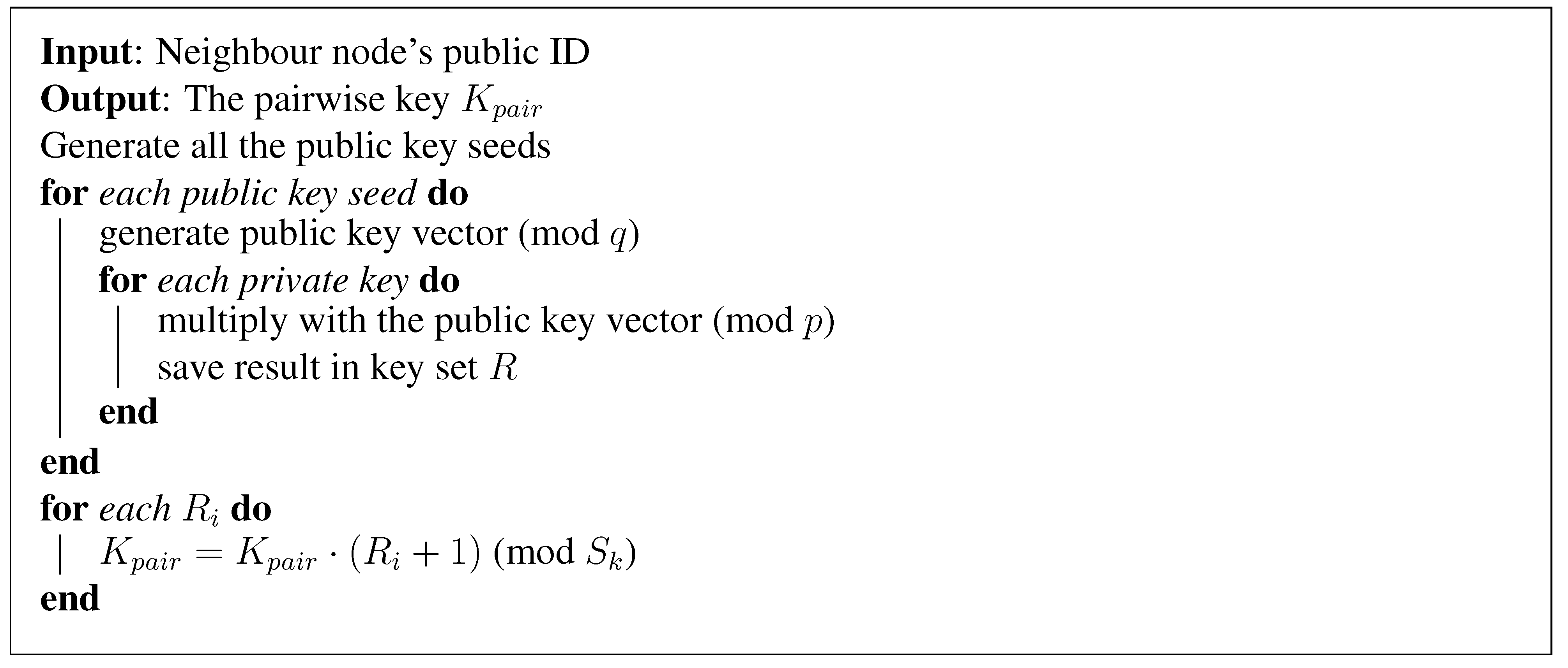
6.1.3. Compact Code
The pairwise key computation code is very simple and requires only a few steps. The pseudo code is given in Listing 1.
6.1.4. Memory Requirements
During execution, RAM is required for some counters, the pairwise key, some temporary data, the numbers in the pairwise key set and the counterpart’s public keys. While the elements of the public keys need to be computed, it is possible to write the code such that only one element is used at a time, requiring only one memory space in RAM. Overall, the largest amount of RAM required is for the pairwise key, bits, where b is the data size in bits. Since our typical prime modulus is , i.e., bits, we can simplify coding if we use one byte for the data size. The private key set requires the largest storage, bits, or bytes if one byte is used to store each b bit integer. As it is static, it can be stored in ROM.
List 1:.
BYka pairwise key computation pseudo code.
List 1:.
BYka pairwise key computation pseudo code.
6.1.5. Computation Time
The main parts of the computation include generating the public key vectors involving
modulo multiplications and computing the numbers in the pairwise key set involving
modulo multiplications and
modulo additions. The modulo operations are on small integers, except for the final pairwise key computation. The experimental results to obtain the computation times for the BYka scheme in the MICAzmote [
17], which has an eight-bit ATmega128 processor running at 8 MHz with 4 KB RAM, 4 KB EEPROMand 128 KB flash memory, implemented using TinyOS [
18], gave the following linearised result,
6.1.6. Scalability
The scalability of the BYka scheme is limited by the key space sizes of the pairwise keys, private keys and the public keys. Except for the public keys, these key spaces are very large. The public key is limited by the number of the number of sets of public key seeds, . Using , there are about 10,000 possible nodes, while using a 32-bit prime for q, it is possible to have about nodes.
6.2. Implementation
The parameters need to be selected for system performance and the desired level of resilience. In general, larger values of
and
η increase the resilience, but also increase the memory requirements and the computation times. Smaller values of
p reduce the chance of discovering the PPMka information, but also reduce the pairwise key space. A good choice is
, and being a Mersenne prime, the modulo operation can be done very efficiently.
Table 6 can be used as a guide to select the keying parameters for the case using master key matrix size
.
Table 6.
Security and performance features using . is the pairwise key size, traitor node capture size , number of possible master key solutions Φ. Computation times are for the MICAz mote with an eight-bit CPU at 8 MHz with 4 KB ROM 4 KB RAM 128 KB flash.
Table 6.
Security and performance features using . is the pairwise key size, traitor node capture size , number of possible master key solutions Φ. Computation times are for the MICAz mote with an eight-bit CPU at 8 MHz with 4 KB ROM 4 KB RAM 128 KB flash.
| | | | | | | |
| | bits | bits | bits | | |
| | | | | | (bytes) | |
| 6 | 6 | | | | | | | 576 | 175 |
| 7 | | | | | | | 672 | 200 |
| 8 | | | | | | | 768 | 225 |
| 7 | 6 | | | | | | | 672 | 229 |
| 7 | | | | | | | 784 | 263 |
| 8 | | | | | | | 896 | 296 |
| 8 | 6 | | | | | | | 768 | 292 |
| 7 | | | | | | | 896 | 335 |
| 8 | | | | | | | 1024 | 379 |
7. Discussions
7.1. Exclusive Communications
Our scheme only enable pairs of nodes belonging to the same TA to establish pairwise keys with each other. There is no possibility for pairwise key establishment with non-member nodes, which can be a desirable feature for sensor networks.
7.2. Key Escrow
The trusted authority is the key escrow entity and must be well protected. The TA is able to obtain all of the keys and decipher all previously recorded messages. This may be a desirable feature within some organisations. In the BYka scheme, the master keys generation and storage can be dispersed among a committee of TA’s. In this way, protection against some rouge TA’s is possible, since they must all work together to generate the full set of keys.
7.3. Compromised Key
If the private keys of a node are obtained, the adversary is able to obtain all previous keys and decrypt all previously recorded messages. There is no perfect forward secrecy. In addition, the BYka scheme is vulnerable to the compromised-key impersonation attack where, if a node C is compromised, an adversary E cannot only impersonate node C, it can also use the stolen keys to impersonate any other nodes to communicate with C. For example, node E has obtained node C’s keys. It impersonates node B and sends to node C, which uses it to compute the pairwise key . Unknown to C, node E also uses with C’s private keys to compute the same pairwise key .
8. Conclusion
We proposed a new authenticated key agreement scheme where pairs of nodes, having obtained each other’s public key IDs, can compute large common pairwise keys using their private keys obtained from the same trusted authority. The initial public key exchange is only a few bits, the size of the public key ID, a 16 bit integer, saving on time and energy. The computations use simple modulo arithmetic operations on small integers, making it fast, efficient and requiring few resources. These features make it very attractive for use as the cryptographic primitive for secure communications in low-resource devices, such as wireless sensor nodes, especially in ad hoc and mobile network applications.
We analysed the security of the scheme against a powerful attacker who is able to capture any number of nodes and extract all of the keying material. Our analysis showed that the captured keys cannot be used directly to break the scheme. The attacker must first discover for each private key the public key and master key used to compute it, i.e., the private-public-master-key associations (PPMka).
We showed how an attacker may use captured nodes to discover the PPMka information. We obtained analytical results to calculate the probabilities of successfully breaking the scheme using these compromised nodes. These results were verified using computer simulated attacks. We showed that using suitable keying parameters, the attacker would need to capture tens of thousands of nodes or, alternatively, try an unfeasibly large number of solutions. The probability of breaking the scheme would be so small, that it is virtually unconditionally secure.
Finally, we presented some implementation parameters to achieve the desired performance in terms of computation time, key size and memory requirements for the MICAz mote.


