1. Introduction
Wireless ad hoc networks (WAHNs) are self-organizing wireless networks without infrastructure support, delivering of packet frames from a source node to a destination node via routing with multi-hop relaying through other nodes in the networks. Packet frames are stored and forwarded by the intermediate nodes from the source and destination nodes. There are multiple source and multiple destination nodes in the WAHNs. WAHNs have dynamic topology, possible limited battery, limited bandwidth, and are less secured as compared to wired networks. As compared to cellular networks, WAHNs have more rapid deployment and less setup time. In addition, WAHNs are mostly built upon basic medium access control (MAC) protocol like IEEE 802.11 Distributed Coordination Function (DCF) MAC in the Ad Hoc Topology. IEEE 802.11 DCF is not very suitable for WAHNs. Thus, modifications of the basic IEEE 802.11 DCF MAC are needed in WAHNs. Some applications of WAHNs are used in military networks, unmanned autonomous vehicles (UAVs) networks, community networks, home networks, disaster response networks, vehicle networks and sensor networks.
Wireless sensor network (WSN) is a sub-class of WAHN. WSNs are similar to WAHNs, where sensors act as network nodes. Intermediate sensor nodes can act as relays for the source and destination sensor nodes. The main differences for WSNs from WAHNs are that the number of sensor nodes can be several orders of magnitude higher than that of WAHNs, the sensor nodes are densely deployed, and the sensor network topology changes very frequently due to node failures. In addition, the sensor nodes have limited power, memory and computing capacities and they may not have global identities due to the large number of sensors. Furthermore, it may be hard to recharge the batteries of sensor nodes. Some applications of WSNs are used in military networks, home networks and health-care networks.
Wireless ad hoc and sensor networks (WAHSNs) traditionally use omni-directional antennas. However, directional antennas bring about many benefits for WAHSNs. Thus, the focus of this survey is on directional MAC protocols in WAHSNs. State-of-the-art directional medium access control (DMAC) protocols in WAHSNs are presented in this survey. There are many key benefits of directional antennas over omni-directional antennas. However, directional antennas lead to other problems for DMAC protocols. Addressing these problems and benefits for directional antennas to MAC protocols leads to many classes of DMAC protocols in WAHSNs. These classes of DMAC protocols presented in this survey include single-channel, multi-channel, cooperative and cognitive DMACs. Single-channel DMAC protocols can be classified as contention-based or non-contention-based or hybrid-based, while multi-channel DMAC protocols commonly use a common control channel for control packets/tones and one or more data channels for directional data transmissions.
Cooperative DMAC protocols improve throughput in WAHNs via directional multi-rate/single-relay/multiple-relay/two frequency channels/polarization, while cognitive DMAC protocols leverage on conventional DMAC protocols with multi-channel with new twists to address the active primary users in the data channels for dynamic spectrum access.
Figure 1 shows the classification of DMAC protocols in WAHNs. For WAHNs, contention-based single-channel DMAC protocols can be classified into pure RTS/CTS-based, tone/pulse-based and power-controlled-based DMAC protocols. Non-contention-based MAC protocols include TDMA, FDMA and CDMA multiple access methods.
Figure 1.
Classification of Directional Medium Access Control (DMAC) Protocols in Wireless Ad Hoc Networks.
Figure 1.
Classification of Directional Medium Access Control (DMAC) Protocols in Wireless Ad Hoc Networks.
Only a pure spatial reuse TDMA DMAC protocol is briefly presented. Hybrid single-channel DMAC protocols include slotted DMAC protocol, contention-window or random-access/directional DATA (DDATA)/directional acknowledgement (DACK) periods DMAC protocols, search/poll/data transfer periods DMAC protocols and neighbor-discovery/reservation/data transmission periods DMAC protocols.
In addition, contention-based multi-channel DMAC protocols can be classified as tone-based, control-channel-based, non-control-channel-based and power-controlled-based DMAC protocols in WAHNs. The authors are not aware of any non-contention-based multi-channel DMAC protocol in WAHNs in the literature.
Furthermore, for contention-based and tone-based multi-channel DMAC protocols in WAHNs, tones are transmitted in the control channel in addition to different types of Request-To-Send/Clear-To-Send (RTS/CTS) control frames’ transmissions and DDATA/DACK frames’ transmissions. The tones are used to reserve the data channel for DDATA frame transmission and on many occasions for DACK frame transmission as well. Only non-circular contention-based and tone-based multi-channel DMAC protocols are presented as the authors are not aware of any circular contention-based and tone-based multi-channel DMAC protocol for WAHNs in the literature.
In control-channel-based and contention-based multi-channel DMAC protocols in WAHNs, there are one control channel and one or more data channels with a total of n channels. In general, the control channel is used for control frames, while the data channels are used for DDATA/DACK frames, but there is an exception.
In a non-control-channel-based and contention-based multi-channel DMAC protocol in WAHNs, there are n data channels. All frames are transmitted in a chosen free data channel. Channel allocation is assumed to be static.
For power-control-based and contention-based multi-channel DMAC protocols in WAHNs, they are also control-channel-based. In this control-channel-based, power-control-based and contention-based multi-channel DMAC protocols, there are one control channel and one or more data channels with a total of n channels. Note that only non-circular types of RTS/CTS frame transmissions are presented. Circular type of control frame transmission for this class of DMAC protocol is not available from the authors’ knowledge. There is also a hybrid-based multi-channel DMAC protocol using ATIM Window/DDATA/DACK periods.
Contention-based single-channel and two-channel cooperative DMAC protocols for WAHNs are presented in this survey. Both non-circular and circular types of DMAC protocols for this class are available in the literature. Contention-based multi-channel non-circular cognitive DMAC protocols with and without polarization for dynamic spectrum access in Cognitive Ad Hoc Networks are also presented in this survey. For the cognitive DMAC protocol without polarization, a hybrid DMAC protocol is presented.
Pure RTS/CTS-based DMAC protocols can be classified as non-circular-based and circular-based. For non-circular-based type of pure RTS/CTS-based DMAC protocols, they can be classified as ORTS/OCTS-based, DRTS/OCTS-based and DRTS/DCTS-based. The prefix “O” stands for omni-directional, while the prefix “D” stands for directional. On the other hand, for circular-based type of pure RTS/CTS-based DMAC protocols, they can be classified as CRTS/DCTS-based and CRTS/CCTS-based. The prefix “C” stands for circularly directional.
Figure 2 shows the classification of DMAC protocols in WSNs. For WSNs, there are only single-channel and multi-channel DMAC protocols.
Single-channel DMAC protocols can be classified as contention-based, non-contention-based and hybrid-based. Contention-based single-channel DMAC protocols can be classified into pure RTS/CTS-based and power-controlled-based DMAC protocols, while a non-contention-based single-channel DMAC protocol can be classified as synchronization-based. On the other hand, a hybrid-based single-channel DMAC can be classified as Synchronization/Allocation/Data Transfer-Period-based. Only contention-based, control-channel-based multi-channel-based DMAC protocol is presented. Cooperative and cognitive DMAC protocols have not been proposed for WSNs in the literature according to the authors’ knowledge. Pure RTS/CTS-based DMAC protocols can be classified as non-circular-based and circular-based. For non-circular-based type of pure RTS/CTS-based DMAC protocols, they can be classified as ORTS/OCTS-based and DRTS/DCTS-based. On the other hand, for circular-based type of pure RTS/CTS-based DMAC protocols, there is only a DRTS/CCTS-based DMAC protocol.
Figure 2.
Classification of DMAC Protocols in Wireless Sensor Networks.
Figure 2.
Classification of DMAC Protocols in Wireless Sensor Networks.
There are survey papers for DMAC protocols for WAHNs in the literature [
1,
2,
3,
4,
5,
6]. The differentiating factor in this survey paper for DMAC protocols is in its main contribution. The main contribution of this survey paper is step-by-step DMAC protocol sequences illustrations for the main representative DMAC protocols in each classification of the DMAC protocols in WAHSNs. This is the key difference between traditional DMAC protocols surveys and this survey. The step-by-step DMAC protocol sequences show not only the sequences of the control frames, data frame(s), acknowledgement frame(s) and tones, they also show the directivity of these frames and tones, whether they are omni-directional or partial or restricted-directional or one-way-directional, and the communication ranges of these frames and tones, depending on the power control on them. Therefore, the visual effect of these DMAC protocol sequences illustrated by color-coded frames aids to highlight and illuminate the understanding of these DMAC protocols. The main representative DMAC protocols and their variants are pillars for future design of DMAC protocols for WAHSNs. Thus, the unified key idea presentations of these main representative DMAC protocols in many cases, under one roof, allow leverage for new future DMAC protocol design in WAHSNs.
The main representative DMAC protocols presented in this survey may not be exhaustive, but it serves the purpose of having a unified view of the main representative DMAC protocols in WAHSNs.
The outline of this survey is as follows. An introduction is presented in
Section 1. The network topologies for WAHSNs are presented in
Section 2.
Section 3 discusses the key benefits and problems of directional antennas. A generic DMAC protocol in WAHSNs is presented in
Section 4.
Section 5,
Section 6,
Section 7 and
Section 8 respectively survey single-channel, multi-channel, cooperative and cognitive DMAC protocols in WAHNs.
Section 9 and
Section 10 respectively survey single-channel and multi-channel DMAC protocols in WSNs. Open issues for DMAC protocols in WAHSNs are discussed in
Section 11. Finally, conclusions are made in
Section 12.
2. Network Topologies
The network topologies for WAHSNs are presented in this section. They include random network topology, regular network topology and linear network topology for WAHNs and layered topology, homogeneous and single-tier clustered topology, heterogeneous and single-tier clustered topology, and heterogeneous and multi-tier clustered topology, and new heterogeneous and single-hop clustered topology with power control and multi-reception from the same cluster head to the base stations for WSNs.
2.1. Wireless Ad Hoc Networks
The random network topology, the regular network topology and the linear network topology for WAHNs are shown in
Figure 3,
Figure 4 and
Figure 5. Although the nodes are illustrated as laptops in these figures, they can also be wireless ad hoc communication equipment.
Figure 3.
Random Network Topology with nodes A to G.
Figure 3.
Random Network Topology with nodes A to G.
Figure 4.
Regular Network Topology with nodes A to I.
Figure 4.
Regular Network Topology with nodes A to I.
Figure 5.
Linear Network Topology with nodes A to F.
Figure 5.
Linear Network Topology with nodes A to F.
2.2. Wireless Sensor Networks
The layered topology, clustered topology and new clustered topology for WSNs are shown in
Figure 6,
Figure 7 and
Figure 8. In the layered topology, the paths from the sensor nodes in the other layers from the base station to the base station can go through other intermediate layers sensors like a mesh topology.
Figure 6.
Layered Topology.
Figure 6.
Layered Topology.
Figure 7.
Clustered Topology (a) Homogeneous Sensors and Single-Tier; (b) Heterogeneous Sensors and Single-Tier (c) Heterogeneous Sensors and Multi-Tier.
Figure 7.
Clustered Topology (a) Homogeneous Sensors and Single-Tier; (b) Heterogeneous Sensors and Single-Tier (c) Heterogeneous Sensors and Multi-Tier.
Figure 8.
New Clustered Topology: Heterogeneous Sensors for Single-Hop Multi-Reception from the Same Cluster Head to the Base Stations with Power Control.
Figure 8.
New Clustered Topology: Heterogeneous Sensors for Single-Hop Multi-Reception from the Same Cluster Head to the Base Stations with Power Control.
The advantage of such a topology is that another path can be selected if a link on a particular path from a sensor to the base station fails. In the clustered topology, it can be classified as homogeneous sensors and single-tier, heterogeneous sensors and single-tier, and heterogeneous sensors and multi-tier. In the clustered topology for single-tier, the whole network is divided into smaller regions, where local sensor information is forwarded to the local cluster head. Each of the cluster heads in the smaller local regions forwards the collected information to the base station. It is like a spanning tree or star topology within another star topology. With such a topology, if one of the cluster heads fails, the information from that local region fails to be delivered, while if the base station fails, the information from all the local regions covered by the base station fails to be delivered. The generation mechanisms of such a topology can be found in [
1]. For the clustered topology with multi-tier, the cluster head further from the base station forwards the collected information from its local region to the next nearer cluster head which forwards this information together with its collected information to the final nearest cluster head which can forward all the collected information to the base station. The base station can be connected to the Internet to a sink node or it can also be the sink node, while the sensors are the source nodes. In the latter two classifications for clustered topology, the sensors can be data, audio and video sensors, not just data sensors.
For the new clustered topology, there are also heterogeneous sensors. However, each cluster head sends multi-same-packet concurrently to the surrounding base stations in one-hop via power control. Power control to different base stations are needed as the different paths from a cluster head to the base station may not be equal. Furthermore, the power control mechanism may be open loop or closed loop in 3G or 4G cellular networks. The base stations are connected to the Internet to a sink node, where the multiple same packets are processed. Note that a WSN can also have linear topology.
3. Key Benefits and Problems of Directional Antennas
The key benefits of directional antennas over omni-directional antennas are longer communication range, less multipath interference, more spatial reuse, more secure communications, higher throughput and reduced latency [
2,
3,
4,
5,
6,
7,
8].
For the same transmit power, the range of a directional antenna is extended beyond that of an omni-directional antenna. Due to the limited beam width of a directional antenna, the multipath interference is also less as compared to that of an omni-directional antenna. There is also more spatial reuse between pairs of communicating nodes for directional antennas due to less coverage between them as compared to that of omni-directional antennas. Directional antenna minimizes the potential chances of other nodes overhearing the directional transmissions and possible jamming to the directional transmission. Thus, directional antenna provides more secure wireless communications as compared to that of omni-directional antenna. Furthermore, as the signal power is concentrated in a narrow beam, an eavesdropper must be within the beam and in the same direction of the signal. From a comparative study between directional and omni-directional MAC protocols for WAHNs [
8], higher throughput and lower latency are achieved by DMAC protocols as compared to those of omni-directional MAC protocols.
Although directional antennas have key benefits, they also lead to key problems like single-/multi-channel directional hidden/exposed terminals, deafness and neighborhood, head-of-line blocking, and MAC-layer capture [
2,
3,
4,
5,
6,
7,
9,
10,
11] which need to be overcome.
Single-channel directional hidden terminal terminals problem can be due to asymmetry in gain or due to unheard RTS/CTS frame transmissions [
5,
6]. The former problem is shown in
Figure 9, while the latter problem is shown in
Figure 10. Note that the antenna beams are for illustration only and are not drawn to scale in
Figure 9,
Figure 10,
Figure 11,
Figure 12,
Figure 13,
Figure 14 and
Figure 15. A hidden terminal is a node that is not aware of an ongoing directional transmission between a pair of nodes and its directional transmission causes frame collisions with the ongoing transmission. Single-channel exposed terminals problem is a scenario as shown in
Figure 11, where two directional frame transmissions are not possible to co-exist concurrently as one of the directional frame transmission take precedence over the other directional frame transmission, even though their concurrent directional frame transmissions do not collide [
6].
Multi-channel hidden terminal terminals problem is due to a node in a channel, that is not aware of an ongoing directional transmissions between a pair of nodes in another channel, when it jumps into the latter channel and its directional transmission causes frame collisions with the ongoing directional transmissions in that channel. An example is shown in
Figure 12. The reason for changing channel may be to due to a primary user becoming active in the original channel for dynamic spectrum access scenario [
9]. Multi-channel exposed terminals problem is a scenario similar to that for single-channel exposed terminal problem, except that it is in every channel in the multiple channels, for example in non-control-channel-based multi-channel DMAC protocols.
Deafness occurs when a node tries to communicate with another node which is beamformed to another direction [
5,
6] as shown in
Figure 9, where node A is communicating with node B. Node C attempts to communicate with node A directionally, but it is unsuccessful as node A’s directional antenna is directed towards node B.
Figure 9.
Single-Channel Directional Hidden Terminal Problem Due to Asymmetry in Gain (a) Nodes A, B and C in Omni-Directional Receive Mode; (b) Node A sends a Directional RTS (DRTS) Frame to Node B; (c) Node B replies with a Directional CTS (DCTS) Frame; (d) Node A sends a Directional DATA (DDATA) Frame to Node B and Node C finds the Directional Channel to Node B Idle via Directional Carrier Sensing; (e) Node C sends a DRTS Frame to Node A, interfering the DDATA transmission’s reception at Node B and Node C is a Hidden Terminal.
This causes node A to be
deaf to node C. Only when node A switches to omni-directional receive mode, then node A will be able to hear node C. With directional antenna, neighbor discovery algorithms are needed [
6]. Neighbor discovery can be blind discovery or informed discovery.
Figure 13 shows a blind neighbor discovery which requires Global Positioning System (GPS) for time reference line. After one round, all neighbors are discovered.
Head-of-Line (HoL) blocking is the scenario where the second data packet in a node queue can be transmitted to another node, but is blocked because the first data packet cannot be sent to yet another node which is beamformed to another direction for frame transmissions with a corresponding node [
5,
6]. An example of HoL blocking problem is shown in
Figure 14. Lastly, MAC-layer capture problem happens to a node which is in between two communicating nodes, causing it to receive a directional RTS frame from one of the two communicating nodes, decode it and pass it up to the MAC layer from the physical layer [
5]. As the frame is not for it, it drops the frame, but this disables potential concurrent directional communication with another neighboring node as shown in
Figure 15.
Figure 10.
Single-Channel Directional Hidden Terminal Problem Due to Unheard Request-To-Send/Clear-To-Send (RTS/CTS) (a) Nodes A, B, C and D in Omni-Directional Receive Mode; (b) Node A sends a Directional RTS (DRTS) Frame to Node B; (c) Node B replies with a Directional CTS (DCTS) Frame; (d) Node A sends a Directional DATA (DDATA) Frame to Node B; (e) While Node A sends a DDATA Frame to Node B, Node C sends a DRTS Frame to Node D; (f) While Node A is still sending a DDATA Frame to Node B, Node D replies with a DCTS Frame to Node C; (g) Node A sends a Directional ACK (DACK) Frame, while Node C sends a DDATA Frame to Node D; (h) While Node C is sending a DDATA frame, Node A finds the Directional Channel to Node D Idle via Directional Carrier Sensing and sends a DRTS Frame to node D, interfering the DDATA transmission’s reception at Node D and Node A is a Hidden Terminal.
Figure 11.
Single-Channel Directional Exposed Terminal Problem (a) Nodes A, B, C and D in Omni-Directional Receive Mode; (b) Node A sends a Directional RTS (DRTS) Frame to Node B with Full Power; (c) Node B replies with a Directional CTS (DCTS) Frame with Reduced Power; (d) Node A sends a Directional DATA (DDATA) Frame to Node B with Reduced Power and Node C is an Exposed Terminal which could have sent frames to communicate with Node D.
Figure 12.
Multi-Channel Directional Hidden Terminal Problem (a) Nodes A and B is in Omni-Directional Receive Mode in Channel 1, while Node C is in Omni-Directional Receive Mode in Channel 2; (b) Node A sends a Directional RTS (DRTS) Frame to Node B in Channel 1; (c) Node B replies with a Directional CTS (DCTS) Frame in Channel 1 and the Primary User is Active in Channel 2; (d) Node C switches from Channel 2 to Channel 1, while Node A sends a Directional DATA (DDATA) Frame to Node B; (e) Node C finds the Directional Channel to Node A Idle via Directional Carrier Sensing in Channel 1 and sends a DRTS Frame to Node A, interfering the DDATA transmission’s reception at Node B and Node C is a Hidden Terminal in Channel 1.
Figure 13.
Single-Channel Directional Blind Neighbor Discovery (a) Nodes A, B and C in Omni-Directional Receive Mode; (b) All nodes send a Frame according to the Reference Time Line (RTL); (c) Node B replies with Frame Opposite to the Reference Time Line; (d) All Nodes send a Frame according to the Next RTL; (e) Node C replies with a Frame; (f) All Nodes send a Frame according to the Next RTL; (g) No reply; (h) All Nodes send a Frame according to the Next RTL; (i) Node C replies with a Frame; (j) All Nodes send a Frame according to the Next RTL; (k) Node A replies with a Frame; (l) All Nodes send a Frame according to the Next RTL.
Figure 14.
Directional Head-of-Line (HoL) Blocking Problem (a) Nodes A, B, C and D in Omni-Directional Receive Mode; (b) Node A sends a Directional RTS (DRTS) Frame to Node B; (c) Node B replies with a Directional CTS (DCTS) Frame; (d) Node A sends a Directional DATA (DDATA) Frame to Node B and Node C has a Packet for transmission to Node A; (e) Node C sends a DRTS Frame to Node A but unsuccessful and Node C has another Packet for Node D; (f) Node C sends another DRTS Frame to node A but unsuccessful and Node C has another Packet for Node D. The HoL Packet at Node C for Node A blocks the other Packets from Node C to Node D to be transmitted.
Figure 15.
Directional MAC-Layer Capture Problem (a) Nodes A, B, C and D in Omni-Directional Receive Mode; (b) Node A sends a Directional RTS (DRTS) Frame to Node B with Full Power; (c) Nodes B and C reply with Directional CTS (DCTS) Frames with their Corresponding Reduced Powers and Node D attempts to Communicate with Node C with a DRTS Frame but is Unsuccessful; (d) Node A sends a Directional DATA (DDATA) Frame to Node B with Reduced Power and Potential Communication between Nodes C and D is Wasted due to MAC-Layer Capture at Node C.
4. Generic Directional Medium Access Control (DMAC) Protocols for Wireless Ad Hoc and Sensor Networks
In general, DMAC protocols in WAHSNs uses RTS frame and CTS frame exchange to reserve the channel with Carrier Sense Multiple Access with Collision Avoidance (CSMA/CA), similar to IEEE 802.11 Distributed Coordination Function (DCF) MAC protocol with omni-directional transmissions. The RTS/CTS frames exchange can be omni-directional or directional in WAHSNs. That is, there can be omni-directional RTS and omni-directional CTS (ORTS/OCTS) frames exchange, ORTS and directional CTS (ORTS/DCTS) frames exchange, directional RTS and OCTS (DRTS/OCTS) frames exchange, and DRTS and DCTS (DRTS/DCTS) frames exchange. Furthermore, for ORTS and OCTS frames, they can also be transmitted in all antennas sectors with the same range as for omni-directional antenna by controlling the transmit power or extended range with up to the maximum transmit power.
Before transmitting the RTS frame(s) when its backoff counter value counts down to zero, the source node senses the channel and checks that its directional network allocation vector(s) (DNAV(s)) [
12] is/are inactive before transmitting the RTS frame(s) after a Distributed InterFrame Space (DIFS) duration. Neighboring nodes overhearing one of these combinations of RTS/CTS frames exchange set their DNAVs and will not transmit any frame during the DNAV period.
With successful combinations of RTS/CTS exchange, either omni-directionally or directionally, or a combination of both, the DATA frame and the acknowledgement (ACK) frame are transmitted directionally, that is, DDATA and DACK frames are transmitted.
These generic DMAC frames exchanges are assumed to be successful frame transmissions in the step-by-step DMAC protocols’ sequences. When the transmitting node transmits the ORTS or DRTS frame, it also set the OCTS or DCTS timer. If no OCTS or DCTS frame is received, the transmitting node backs off after the OCTS or DCTS timer times out and retransmits later if possible.
Every time there is a frame collision, the backoff algorithm kicks in. Initially, a minimum contention window size is selected for the current contention window size and the backoff counter value is selected between zero and the current contention window size. The backoff counter counts down when the channel is idle and freezes when the channel is busy. If there is a frame collision and the maximum retry limit is not reached, the current contention window size is doubled and one is added. Then, the backoff counter value is selected between zero and the current contention window size. Similarly, the backoff counter counts down when the channel is idle and freezes when the channel is busy. If there is a frame collision and the maximum retry limit is reached, the data packet is discarded and a new data packet is selected for transmission.
Note that there is a Short InterFrame Space (SIFS) between each of the RTS/CTS frames, CTS/DDATA frames and DDATA/DACK frames. The RTS/CTS frames can be omni-directional or directional or a combination.
With the SIFS duration shorter than the DIFS duration, an ongoing transmission is not disrupted by any new transmission until the ongoing transmission is over.
There are variations of the generic DMAC protocols. These variations include factors like single-channel, multi-channel, busy tones, transmit powers, contention and non-contention, non-circular and circular RTS(s)/CTS(s), cooperative and cognitive, and hybrid transmissions.
The next six sections survey the DMAC protocols for WAHSNs with these variations.
5. Single-Channel DMAC Protocols in WAHNs
This section presents a survey of single channel DMAC protocols for WAHNs. The key ideas of the single-channel DMAC Protocols for WAHNs are presented in step-by-step sequences, illustrated in figures assuming successful frame transmissions. These step-by-step sequences are also used in other sections for other types of DMAC protocols in WAHNs and WSNs. These figures only serve to illustrate the key ideas but they are not drawn to scale and they do not necessary illustrate the same diagrams in the original references.
Sometimes, there is no diagram to illustrate the key DMAC protocol(s) in the original references; thus, illustrated diagrams in this survey are based on the understanding of the DMAC protocol(s) in the original references in these cases. The figures drawn in this survey attempt to give consistent and simple illustrations of the different key ideas of the DMAC protocols for WAHNs. Sometimes, a DACK frame is added for consistency in this survey. Furthermore, a directional antenna beam is represented by a “pie shape” for simplicity. In reality, a directional antenna beam has not only a main lobe, but also side lobes. Nevertheless, the interested reader can always refer to the original references for specific details and representations.
This section surveys single-channel DMAC protocols. Contention-based, non-contention-based and hybrid-based DMAC protocols are presented. Contention-based DMAC protocols include pure RTS/CTS-based, tone/pulse-based and power-controlled-based DMAC protocols. Note that the directional range of a node can be controlled by power control. Non-contention-based MAC protocols include TDMA, FDMA and CDMA multiple access methods. Only a pure spatial reuse TDMA DMAC protocol is briefly presented. Hybrid DMAC protocols include a slotted DMAC protocol, contention-window or random-access/DDATA/DACK periods DMAC protocols, search/poll/data transfer periods DMAC protocols and neighbor-discovery/reservation/data transmission periods DMAC protocols.
5.1. Contention-Based Single-Channel DMAC Protocols
Directional CSMA/CA MAC protocol is assumed in contention-based DMAC protocols. A node with a DDATA frame can only transmit the RTS frame when its backoff counter count down to zero, the channel is sensed idle and its DNAV(s) for the direction(s) of its antenna(s) is/are off. Contention-based single-channel DMAC protocols use different types of RTS and CTS frames to reserve the channel within the vicinity of the node’s antennas. Multiple M non-circular antennas are assumed. They can be non-circular omni-directional in all directions of its antennas concurrently or non-circular directional in one antenna or circular in sequential directions of its antennas or partial circular in a few sequential directions of a few of its antennas. DDATA and DACK frames are sent after the RTS and CTS frames. Backoff algorithm and CTS timeout, similar to that in IEEE 802.11 CSMA/CA MAC, is assumed unless otherwise stated, except that they are for DMAC protocols.
5.1.1. Pure RTS/CTS-based Single-Channel DMAC Protocols
This subsection surveys pure RTS/CTS-based single-channel DMAC protocols. They include non-circular and circular DMAC protocols. For non-circular DMAC protocols, they can be classified as ORTS/OCTS-based, DRTS/OCTS-based and DRTS/DCTS-based DMAC protocols. For circular DMAC protocols, they can be classified as circular directional RTS/DCTS (CRTS/DCTS)-based and CRTS/circular directional CTS (CRTS/CCTS)-based DMAC protocols using directional CSMA/CA MAC protocol. CRTS frames emulate omni-directional RTS frames, while achieving the benefits of extended communication range and better gain. The idle receiving mode of a node is assumed to be omni-directional, unless otherwise stated.
Pure RTS/CTS-based Single-Channel Non-Circular DMAC Protocols
For pure RTS/CTS-based single-channel non-circular DMAC protocols, no extra delay is incurred in the RTS/CTS frames’ transmissions.
ORTS/OCTS-based Single-Channel Non-Circular DMAC Protocols
Reference [
13] proposes a MAC protocol for mobile ad hoc networks using directional antennas. It is an example of an ORTS/OCTS-based single-channel non-circular DMAC protocol. By using four directional antennas, the throughput of this DMAC protocol is increased by up to 2 to 3 times over that of using omni-directional antennas.
In general, multiple
M non-circular directional antennas are assumed for all nodes in this DMAC protocol. An example for source node A and destination node B is shown in
Figure 16.
M is set to four antenna sectors in the figure. Note that four sectors are just an example; they can be eight sectors, twelve sectors, and so on. Furthermore, a pie is used to represent the antenna beam sector for simplicity of representation.
Figure 16.
Four number of directional antennas (a) For source node A; (b) For destination node B.
Figure 16.
Four number of directional antennas (a) For source node A; (b) For destination node B.
The key idea of the DMAC protocol sequence is as shown in
Figure 17. They are also just for illustration of the key idea only and are not drawn to scale. ORTS frames are transmitted through all of source node A’s four antennas. Node B is the destination node. If nodes C, D and E are not the destination node for the ORTS frames, they block their antennas; this is not good for spatial reuse. When node B receives the ORTS frame in the antenna sector direction from node A, it transmits its OCTS frames through all of its four antennas. If nodes F, G and H are not the source node for the OCTS frames, they also block their antennas. These nodes overhearing the OCTS frames block their antennas; this is also not good for spatial reuse. After receiving the OCTS frame, node A blocks all of its antennas except for the antenna being used for DDATA frame transmission (
i.e., sector 1) sent towards node B and when the DDATA frame is correctly received at node B, it also blocks all of its antennas except for the antenna being used for DACK frame transmission (
i.e., sector 3) sent towards node A.
Figure 17.
DMAC Protocol Sequence for omni-directional RTS and omni-directional CTS (ORTS/OCTS)-based Single-Channel Non-Circular DMAC Protocol (a) ORTSs; (b) OCTSs; (c) DDATA; (d) DACK.
Figure 17.
DMAC Protocol Sequence for omni-directional RTS and omni-directional CTS (ORTS/OCTS)-based Single-Channel Non-Circular DMAC Protocol (a) ORTSs; (b) OCTSs; (c) DDATA; (d) DACK.
Note that the key idea of the DMAC protocol sequence can also be as shown in
Figure 18, where the ORTS and OCTS frames are directional concurrently in each of
M sectorized antennas.
M is set to four antenna sectors in the figure. The main differences in this DMAC protocol with other DMAC protocols in
Section 5.1.1 are in its control frame exchange using ORTS and OCTS frames.
Figure 18.
DMAC Protocol Sequence for Directional Range ORTS/OCTS-based Single-Channel Non-Circular DMAC Protocol (a) Directional Range ORTSs; (b) Directional Range OCTSs; (c) DDATA; (d) DACK.
Figure 18.
DMAC Protocol Sequence for Directional Range ORTS/OCTS-based Single-Channel Non-Circular DMAC Protocol (a) Directional Range ORTSs; (b) Directional Range OCTSs; (c) DDATA; (d) DACK.
With ORTS and OCTS frames, there is no deafness problem. As compared to the DMAC protocol using DRTS/OCTS control frame exchange, in
Section 5.1.1, the advantage of the ORTS/OCTS control frame exchange for the DMAC protocol presented in this subsection is that it does not require the use of Global Positioning System (GPS). As compared to the DMAC protocol using DRTS/DCTS control frame exchange, in
Section 5.1.1, another advantage of the ORTS/OCTS control frame exchange for the DMAC protocol presented in this subsection is that it does not require the use of a neighbor table. However, as compared to the DMAC protocols using DRTS/OCTS and DRTS/ DCTS control frame exchanges, in
Section 5.1.1, respectively, the disadvantage of the ORTS/OCTS frame exchange for the DMAC protocol presented in this subsection is that it requires the ORTS frames to be sent in all antenna sectors and not just via the antenna sector pointing to the destination node. Furthermore, another advantage of using this non-circular DMAC protocol over circular DMAC protocols, in
Section 5.1.1, is that there is no extra delay incurred in the network.
Other variants in ORTS/OCTS-based single-channel non-circular DMAC protocols are in [
14,
15,
16]. Reference [
14] designs two MAC protocols suitable for ad hoc networks based on directional antennas. The DMAC protocols are called D-MAC protocols. One of the D-MAC protocols in this reference is an example of a DRTS or ORTS/OCTS-based single-channel non-circular DMAC protocol. Reference [
15] proposes a selective CSMA protocol with cooperative nulling for ad hoc networks, while reference [
16] proposes a MAC protocol, called NULLHOC, for adaptive antenna array based WAHNs in multipath environments. Another variant is an ORTS/OCTS/OBDTS-based single-channel non-circular DMAC protocol [
17], where OBDTS frame is an omni-directional Beam-Direction-To-Send control frame. It is a space division multiple access (SDMA)-based MAC protocol for WAHNs with smart antennas.
DRTS/OCTS-based Single-Channel Non-Circular DMAC Protocols
Reference [
14] designs two MAC protocols suitable for ad hoc networks based on directional antennas.
The DMAC protocols are called D-MAC protocols. One of the D-MAC protocols in this reference is an example of a DRTS/OCTS-based single-channel non-circular DMAC protocol. It is shown that there is an overall increase in throughput over traditional IEEE 802.11 DCF MAC protocol.
The availability of GPS is assumed for location information and each node shares this location information with its neighbors.
The key idea of the DMAC protocol sequence is as shown in
Figure 19. As the source node A knows the destination node B’s location, node A transmits a DRTS frame to node B. If nodes C, D, and E are not the destination node for the DRTS frame, they block their antennas in the direction of the DRTS frame. When node B receives the DRTS frame in sector 1 of node A, it transmits its OCTS frames through all of its four antennas. Nodes F and G are not the source node for the OCTS frames; they block their antennas in the directions of the OCTS frames. Nodes H and I that are not in the vicinity of the directions of the DRTS frame and the OCTS frames can have spatial reuse.
Figure 19.
DMAC Protocol Sequence for DRTS/OCTS-based Single-Channel Non-Circular DMAC Protocol (a) DRTS; (b) OCTSs; (c) DDATA; (d) DACK.
Figure 19.
DMAC Protocol Sequence for DRTS/OCTS-based Single-Channel Non-Circular DMAC Protocol (a) DRTS; (b) OCTSs; (c) DDATA; (d) DACK.
As node A sends a DRTS frame to node B, node H is not aware of it (deafness) and may send DRTS frames to node A concurrently, causing transmission collisions when node B sends the OCTS frame to node A, or when node B sends the DACK frame to node A concurrently. DRTS frame can cause deafness and hidden terminal problems behind the direction of the source node A’s DRTS frame. Then, node A transmits a DDATA frame to node B. Upon correctly receiving the DDATA frame, node B replies with a DACK frame to node A.
Note that the key idea of the DMAC protocol sequence can also be as shown in
Figure 20, where the OCTS frames are directional concurrently in each of the four sectorized antennas.
Figure 20.
DMAC Protocol Sequence for DRTS/Directional Range OCTS-based Single-Channel Non-Circular DMAC Protocol (a) DRTS; (b) OCTSs; (c) DDATA; (d) DACK.
Figure 20.
DMAC Protocol Sequence for DRTS/Directional Range OCTS-based Single-Channel Non-Circular DMAC Protocol (a) DRTS; (b) OCTSs; (c) DDATA; (d) DACK.
The main differences in this D-MAC protocol with other DMAC protocols in
Section 5.1.1 are in its control frame exchange using DRTS and OCTS frames. As compared to the DMAC protocol using ORTS/OCTS control frame exchange, in
Section 5.1.1, the disadvantage of D-MAC protocol is that the DRTS/OCTS control frame exchange requires the use of GPS. As compared to the DMAC protocol using DRTS/DCTS control frame exchange, in
Section 5.1.1, the DRTS/OCTS control frame exchange of D-MAC protocol does not require the use of a neighbor table and other control frames. However, as compared to the DMAC protocols using DRTS/OCTS and DRTS/ DCTS control frame exchanges, in
Section 5.1.1, respectively, DRTS/OCTS frame exchange requires the DRTS frame to be sent just via the antenna sector pointing to the destination node, but not in all antenna sectors.
The advantage of using this non-circular D-MAC protocol over circular DMAC protocols, in
Section 5.1.1, is that there is no extra delay incurred in the network.
DRTS/DCTS-based Single-Channel Non-Circular DMAC Protocols
Reference [
18] is a DMAC protocol for deafness avoidance (DMAC/DA) in ad hoc networks. It is an example of a DRTS/DCTS-based single-channel non-circular DMAC protocol. It is shown that there is an overall increase in throughput over traditional IEEE 802.11 MAC protocol.
In this DRTS/DCTS-based single-channel non-circular DMAC/DA protocol, every device keeps a neighbor table via past communication history. In each device’s neighbor table, each neighboring node’s identity (ID) is mapped with its beam number. The time of deafness initiated by a Directional Wait-To-Send (DWTS) frame is the deafness time.
Table 1 shows node A’s neighbor table. For example, node D notifies that it will be busy for a deafness time of
TD. The latest transmission times from blocked nodes are used to monitor the link activities of the nodes. For example, consider nodes C’s and E’s link activities. This means that DWTS frames are needed for them. Similarly, there is a neighbor table for node B. All nodes have their own neighbor tables.
An example network topology is shown in
Figure 21. The source node is node A and the destination node is node B. Nodes C, D, E, F, G and H surround nodes A and B. Nodes F and H have link activities of
FRX time and
HRX time in node’s B neighbor table. The key idea of the DMAC protocol sequence is as shown in
Figure 22. As node A has node B’s beam number of sector 1, node A sends a DRTS frame to node B. As node B also has node A's beam number of sector 3, node B replies with a DCTS frame to node A. As nodes C and E have link activities of
CRX time and
ERX time, respectively, in node A’s neighbor table and nodes F and H have link activities of
FRX time and
HRX time, respectively, in node B’s neighbor table, a DWTS frame is sent from node A to node C and a DWTS frame is sent from node B to node F, concurrently. Then, a DWTS frame is sent from node A to node E and a DWTS frame is sent from node B to node H, concurrently. The DWTS frames are transmitted circularly to nodes with link activities to avoid deafness and hidden terminal problems. After that, node A sends a DDATA frame to node B. Node B replies with a DACK frame to node A if the DDATA frame is correctly received.
Table 1.
Node A’s neighbor table.
Table 1.
Node A’s neighbor table.
| Node ID | Beam Number | Deafness Duration | Link Activity |
|---|
| B | 1 | | |
| C | 2 | | CRX Time |
| D | 3 | TD | |
| E | 4 | | ERX Time |
Figure 21.
Network Topology.
Figure 21.
Network Topology.
Figure 22.
DMAC Protocol Sequence for DRTS/DCTS-based Single-Channel Non-Circular DMAC Protocol (a) DRTS; (b) DCTS; (c) DWTSs; (d) DWTSs; (e) DDATA; (f) DACK.
Figure 22.
DMAC Protocol Sequence for DRTS/DCTS-based Single-Channel Non-Circular DMAC Protocol (a) DRTS; (b) DCTS; (c) DWTSs; (d) DWTSs; (e) DDATA; (f) DACK.
The main differences in the DMAC/DA protocol with other DMAC protocols in
Section 5.1.1 are in its control frame exchange using DRTS and DCTS frames. As compared to the DMAC protocol using DRTS/OCTS control frame exchange, in
Section 5.1.1, this DRTS/DCTS control frame exchange does not require the use of GPS. As compared to the DMAC protocol using ORTS/OCTS and DRTS/OCTS control frame exchanges, in
Section 5.1.1, respectively, this DRTS/DCTS control frame exchange requires the use of a neighbor table and other control frames. However, as compared to the DMAC protocol using ORTS/OCTS control frame exchange, in
Section 5.1.1, DRTS/DCTS frame exchange requires the DRTS and DCTS frames to be sent just via the antenna sector pointing to the destination node and source node, respectively, not in all antenna sectors. The advantage of using this non-circular DMAC/DA protocol over circular DMAC protocols, in
Section 5.1.1, is that there is no extra delay incurred in the network. In this DMAC/DA protocol, the disadvantages are that additional control frames of DWTS with source/destination addresses and the number of DWTS frames and neighbor tables are needed.
Other variants of DRTS/DCTS-based single-channel non-circular DMAC protocols can be found in [
19,
20,
21,
22,
23,
24,
25]. Reference [
19] proposes a basic DMAC protocol and a multi-hop RTS MAC protocol. The basic DMAC is often used as a comparison for other DMAC protocols. Reference [
20] proposes a DMAC protocol that avoids HoL blocking in mobile ad hoc networks, while reference [
21] proposes a receiver-initiated DMAC protocol for handling deafness in ad hoc networks. On the other hand, reference [
22] proposes an opportunistic DMAC protocol for multi-hop wireless networks with switched beam directional antennas, while reference [
23] proposes a distributed asynchronous directional-to-directional MAC protocol for WAHNs. References [
24,
25] propose a MAC protocol for directional antenna (MDA) for WAHNs. Note that concurrent CRTS/CCTS frames are transmitted after DRTS/DCTS frames in [
24,
25]. Reference [
26] is a variant of [
24,
25] and it is a selectively DMAC (SDMAC) protocol for wireless mobile ad hoc networks.
Another variant that can send multiple DDATA frames concurrently to other neighboring nodes for DRTS/DCTS-based single-channel non-circular DMAC protocols can be found in [
27,
28].
The DMAC protocol is an on-demand medium access in multi-hop wireless networks with multiple beam smart antennas. All nodes use multi-beam smart antennas. Each node can either transmit or receive simultaneously but not both; each node can initiate more than one simultaneous frame transmissions or receptions. The idea of concurrent packet receptions employs local synchronization at the nodes. The key idea of the DMAC protocol sequence is as shown in
Figure 23. The source node A has DDATA frames to send to destination nodes B and C. It sends a DRTS frame in the direction of node B and a DRTS frame in the direction of node C and directional scheduling (DSCH) frames in the other two beam directions concurrently where there are neighboring nodes. After that node A
receives concurrent DCTS frames from nodes B and C, while nodes B and C send concurrent DSCH frames to their other beam directions where there are neighboring nodes. Note that the directions of the arrows for the concurrent frames reception at node A from nodes B and C are pointing towards node A. Then, node A
sends two concurrent DDATA frames to nodes B and C, respectively. Then, node A
receives concurrent DACK frames from nodes B and C. Similarly, note that the directions of the arrows for the concurrent frames reception at node A from nodes B and C are pointing towards node A.
Figure 23.
DMAC Protocol Sequence for DRTS/DCTS-based Single-Channel Non-Circular DMAC Protocol (a) Concurrent DRTSs and DSCHs Transmission; (b) Concurrent DCTSs Reception and DSCHs Transmission; (c) Concurrent DDATAs Transmission; (d) Concurrent DACKs Reception.
Figure 23.
DMAC Protocol Sequence for DRTS/DCTS-based Single-Channel Non-Circular DMAC Protocol (a) Concurrent DRTSs and DSCHs Transmission; (b) Concurrent DCTSs Reception and DSCHs Transmission; (c) Concurrent DDATAs Transmission; (d) Concurrent DACKs Reception.
Pure RTS/CTS-based Single-Channel Circular DMAC Protocols
For pure RTS/CTS single-channel circular DMAC protocols, circular transmissions of RTS/CTS frames increase the delay to the network. Nevertheless, remember that CRTS frames emulate omni-directional RTS frames, while achieving the benefits of extended communication range and better gain. Thus, it is a tradeoff.
CRTS/DCTS-based Single-Channel Circular DMAC Protocols
Reference [
29] proposes a MAC protocol to fully exploit the benefits of directional antennas, increase of spatial reuse, coverage range and network capacity.
It is a CRTS/DCTS-based single-channel circular DMAC protocol. It is shown to increase throughput as compared to D-MAC protocol presented in
Section 5.1.1.
In one of these CRTS/DCTS-based single-channel circular DMAC protocols, every device keeps a location table via the CRTS frames. For example,
Table 2 shows the destination node B’s location table.
The key idea of the DMAC protocol sequence is as shown in
Figure 24. In the CRTS/DCTS DMAC protocol, node A transmits CRTS frames circularly. Node B replies with a DCTS frame towards node A. Thus, these nodes that are behind node B may send frames towards node B and may cause collision when node B is transmitting its DCTS frame to node A. This is a hidden terminal problem. Nodes that receive the CRTS frames from node A or the DCTS frame from node B block their corresponding antennas. Source/destination addresses, source beam and destination beam are needed in the CRTS frames and the DCTS frame. Deafness and hidden terminal problems exist as the DCTS frame from node B is sent directionally. Spatial reuse is good as location tables are kept by the nodes. Node A sends the DDATA frame to node B. Upon correctly receiving the DDATA frame from node A, node B replies with a DACK frame to node A.
Table 2.
Node B’s location table.
Table 2.
Node B’s location table.
| Me | Neighbor | My Beam | Neighbor’s Beam |
|---|
| B | A | 5 | 1 |
The main differences in this DMAC protocol with other DMAC protocols in
Section 5.1.1 are in its control frame exchange using CRTS and DCTS frames. As compared to the DMAC protocol using DRTS/OCTS control frame exchange, in
Section 5.1.1, this CRTS/DCTS control frame exchange does not require the use of GPS. As compared to the DMAC protocol using ORTS/OCTS and DRTS/OCTS control frame exchanges, in
Section 5.1.1, respectively, this CRTS/DCTS control frame exchange requires the use of a location table and CRTS control frames. However, as compared to the DMAC protocol using ORTS/OCTS control frame exchange, in
Section 5.1.1, CRTS/DCTS frame exchange requires the CRTS frames to be sent in all directions in sequence and the DCTS frame to be sent just via the antenna sector pointing to the source node, not in all antenna sectors. Furthermore, as compared to the DMAC protocol using CRTS/CCTS control frame exchange, in
Section 5.1.1, CRTS/DCTS frame exchange requires the DCTS frame to be sent just via the antenna sector pointing to the source node, not in all antenna sectors in sequence. The disadvantage of using this circular DMAC protocol over non-circular DMAC protocols, in
Section 5.1.1, is that there is extra delay incurred in the network. Note that sweeping CRTS frames transmissions need more energy in general as compared to a simple ORTS frame transmission.
Figure 24.
DMAC Protocol Sequence for CRTS/DCTS-based Single-Channel Non-Circular DMAC Protocol (a) CRTS; (b) CRTS; (c) CRTS; (d) CRTS; (e) CRTS; (f) CRTS; (g) CRTS; (h) CRTS; (i) DCTS; (j) DDATA; (k) DACK.
Figure 24.
DMAC Protocol Sequence for CRTS/DCTS-based Single-Channel Non-Circular DMAC Protocol (a) CRTS; (b) CRTS; (c) CRTS; (d) CRTS; (e) CRTS; (f) CRTS; (g) CRTS; (h) CRTS; (i) DCTS; (j) DDATA; (k) DACK.
Another variant of such a DMAC protocol is reference [
30]. It is a pencil-beam DMAC for wireless mesh networks.
CRTS/CCTS-based Single-Channel Circular DMAC Protocols
Reference [
31] is a MAC protocol for handling asymmetry in gain in directional antenna equipped ad hoc network. It is a CRTS/CCTS-based single-channel circular DMAC protocol. Results show that the throughput this DMAC protocol can be better than that of the DMAC protocol presented in the results in reference [
29], for a number of scenarios.
In this CRTS/CCTS-based single-channel circular DMAC protocol, every device keeps a location table.
The key idea of the DMAC protocol sequence is as shown in
Figure 25. In the CRTS/CCTS DMAC protocol, node A transmits CRTS frames circularly. Node B sends the Circular Directional CTS (CCTS) frames circularly, but partially to non-overlapping area from node A’s CRTS frames. Neighboring nodes that receive either the CRTS frames from node A or the CCTS frames from node B block their corresponding antennas. Deafness and hidden terminal problems are reduced in the CRTS/CCTS DMAC protocol. Source/destination addresses, source beam and destination beam information are needed in the CRTS frames and CCTS frames. Then, node A transmits the DDATA frame to node B. Node B replies with a DACK frame to node A if the DDATA frame is correctly received. With CRTS frames, there is no deafness problem in the vicinity of node A.
The main differences in this DMAC protocol with other DMAC protocols in
Section 5.1.1 are in its control frame exchange using CRTS and CCTS frames. As compared to the DMAC protocol using DRTS/OCTS control frame exchange, in
Section 5.1.1, the advantage of this DMAC protocol is that the CRTS/CCTS control frame exchange does not require the use of GPS. As compared to the DMAC protocol using ORTS/OCTS and DRTS/OCTS control frame exchanges, in
Section 5.1.1, respectively, the disadvantages of this DMCAP protocol, are that it requires the use of a location table and CRTS/CCTS control frames. However, as compared to the DMAC protocol using ORTS/OCTS control frame exchange, in
Section 5.1.1, CRTS/CCTS control frame exchange requires the CRTS/CCTS frames to be sent in all directions in sequence, not via all antenna sectors at the same time.
Figure 25.
DMAC Protocol Sequence for CRTS/CCTS-based Single-Channel Non-Circular DMAC Protocol (a) CRTS; (b) CRTS; (c) CRTS; (d) CRTS; (e) CRTS; (f) CRTS; (g) CRTS; (h) CRTS; (i) CCTS; (j) CCTS; (k) CCTS; (l) CCTS; (m) CCTS; (n) CCTS; (o) DDATA; (p) DACK.
Figure 25.
DMAC Protocol Sequence for CRTS/CCTS-based Single-Channel Non-Circular DMAC Protocol (a) CRTS; (b) CRTS; (c) CRTS; (d) CRTS; (e) CRTS; (f) CRTS; (g) CRTS; (h) CRTS; (i) CCTS; (j) CCTS; (k) CCTS; (l) CCTS; (m) CCTS; (n) CCTS; (o) DDATA; (p) DACK.
Furthermore, as compared to the DMAC protocol using CRTS/DCTS control frame exchange, in
Section 5.1.1, CRTS/CCTS frame exchange requires the CCTS frame to be sent via all antenna sectors in sequence, not just via the antenna sector pointing to the source node for DCTS frame. The disadvantage of using this circular DMAC protocol over non-circular DMAC protocols, in
Section 5.1.1, is that there is extra delay incurred in the network. Remember that a location table must be kept in each node. These location tables in the nodes help to maintain good spatial reuse.
Other variants of such a DMAC protocol are in references [
32,
33]. Reference [
32] enables efficient access for WAHNs with directional antennas, while reference [
33] is another circular DMAC protocol with performance analysis.
5.1.2. Tone/Pulse-based Single-Channel DMAC Protocols
For tone-based single-channel DMAC protocols, tones are transmitted in the data channel in addition to different types of RTS/CTS frames’ transmissions and DDATA/DACK frames’ transmissions. The tones are used to reserve the data channel for DDATA and DACK frame transmissions as well. A pulse can be used to act as a DRTS frame. Tones can be continuous busy tone signals or On/Off signals.
Tones can be transmitted omni-directionally or directionally as well, while a pulse is just a signal. Extra energy is needed for tone transmissions. Non-circular Tone/Pulse-based DMAC protocols are presented in this Subsection. The authors are not aware of any circular Tone/Pulse-based single-channel DMAC protocols in the literature.
ORTS/OCTS-based or DRTS/DCTS-based Single-Channel Omni-Directional- or Directional Pulse/Tone Non-Circular DMAC Protocol
Reference [
34] is a DMAC protocol using directional pulse/tone channel reservation (DPTCR). It is an ORTS/OCTS-based or DRTS/DCTS-based Single-Channel Omni-Directional- or Directional Pulse/Tone Non-Circular DMAC Protocol. It is shown that the throughput of DPTCR is better than that of directional virtual carrier sensing (DVCS) in reference [
12].
Figure 26.
DMAC Protocol Sequence for ORTS/OCTS- or DRTS/DCTS-based Single-Channel Omni-Directional- or Directional-Pulse/Tone Non-Circular DMAC Protocol (a) O-Pulse Or D-Pulse or ORTS or DRTS in the Data Channel (DC); (b) O-Tone Or D-Tone or OCTS or DCTS in the Data Channel (DC); (c) DDATA in the Data Channel; (d) DACK in the Data Channel; (e) DDATA in the Data Channel; (f) DACK in the Data Channel.
In this DMAC protocol, all frames, including pulse and tone are transmitted in the data channel; that is, only a single channel is used. More explicitly, pulse and tone signals are transmitted in-band. It is assumed that the pulse and tone signals can be transmitted and detected in less than 5 µs. The key idea of the DMAC protocol sequence is as shown in
Figure 26. After its backoff, the source node A can send a pulse signal omni-directionally (O-Pulse) or directionally (D-Pulse) to node B to reserve the channel for node A. These signals act as an ORTS frame and a DRTS frame, respectively. Similarly, the destination node B sends a tone signal omni-directionally (O-Tone) or directionally (D-Tone) to node A to reserve the channel for node B. These signals act as an OCTS and a DCTS, respectively. Then, node A sends the DDATA frame to node B. Then, node B replies with a DACK frame to node A. Other pairs of DDATA and DACK frames can be sent directionally from node A to node B and from node B to node A, respectively.
The main difference of DPTCR protocol as compared to the multiple-radio contention-based and tone-based multi-channel DMAC protocols, in Subsection 6.1.1, is that both tones and pulses are used instead of just tones. The advantage of DPTCR protocol is that it requires only single-channel with one radio as compared to the multiple-radio contention-based and tone-based multi-channel DMAC protocols in
Section 6.1.1. The disadvantage of DPTCR protocol is that pulses have to be generated on top of generating tones.
Other Tone-based Single-Channel DMAC Protocol
Reference [
35] is a Tone-based single-channel DMAC protocol. This DMAC protocol is used to mitigate the unheard RTS/CTS problem in switched beam antennas networks. The DMAC protocol uses a combination of three features to combat the problem. The features include fragmentation of packets, the use of a tone signal to alert potential collision-causing nodes during ongoing transmission and the use of a pause period when a transmission is likely to lead to a collision [
35]. This DMAC protocol does not assume the use of separate data and control channels.
The main difference of this tone-based DMAC protocol as compared to DPTCR in
Section 5.1.2 is that only tones are used instead of both tones and pulses. The advantage of this tone-based DMAC protocol is that it requires only single-channel with one radio as compared to the multiple-radio contention-based and tone-based multi-channel DMAC protocols in
Section 6.1.1. Purely tones are generated in this DMAC protocol; that is, pulses are not generated.
5.1.3. Power Control-based Single-Channel DMAC Protocols
Power control in a node determines the range and quality of a transmission as well the interference that it causes to other nodes [
36]. Thus, it affects the medium access environment for the channel, the throughput of the network and the end-to-end delay in the network. Seven types of power-control based single-channel DMAC protocols are presented in this subsection. Power control can be based on a number of transmit power calculations/formulae in the literature. Note that only non-circular types of RTS/CTS frame transmissions are presented for power-controlled-based single-channel DMAC protocols. On the other hand, the authors are not aware of any circular type of power-controlled-based single-channel DMAC protocols.
ORTS/OCTS-based Single-Channel Non-Circular Power-Controlled DMAC Protocol
Reference [
37] uses a distributed power control and smart antennas for ad hoc networks. It is an ORTS/OCTS-based single-channel non-circular power-controlled DMAC protocol. There is an increase in throughput for this power-controlled DMAC protocol over IEEE 802.11 DCF MAC protocol.
The key idea of the DMAC protocol sequence is as shown in
Figure 27. Node A sends ORTS frames through all of its antennas with full power. After node B receives the ORTS frame from the direction of node A, it replies with OCTS frames through all of its antennas with full power. Then, node A sends the DDATA frame to node B with reduced power.
Upon correctly receiving the DDATA frame, node B replies node A with a DACK frame with reduced power.
The main difference of this DMAC protocol with other DMAC protocols in
Section 5.1.3 is that ORTS/OCTS control frame exchange is used instead of R-ORTS or ORTS/OCTS, R-ORTS or ORTS/DCTS and DRTS or ORTS/DCTS control frame exchanges, respectively. The advantage of this DMAC protocol is that its throughput is better than that of IEEE 802.11 DCF MAC protocol. However, the disadvantage is that power control must be performed.
Scheme 1 of reference [
38] is a variant of such a power-controlled DMAC protocol. This DMAC protocol is similar to the DMAC protocol which uses ORTS/OCTS control frame exchange and DDATA/DACK frames in reference [
13], and is presented in
Section 5.1.1. The throughput of this DMAC protocol is higher than that of IEEE 802.11 DCF MAC protocol. Furthermore, another advantage of using this non-circular power-controlled DMAC protocol over circular DMAC protocols, in
Section 5.1.1, is that there is no extra delay incurred in the network. However, power control is needed.
Figure 27.
DMAC Protocol Sequence for ORTS/OCTS-based Single-Channel Non-Circular Power-Controlled DMAC Protocol (a) ORTSs with Full Power; (b) OCTSs with Full Power; (c) DDATA with Reduced Power; (d) DACK with Reduced Power.
Figure 27.
DMAC Protocol Sequence for ORTS/OCTS-based Single-Channel Non-Circular Power-Controlled DMAC Protocol (a) ORTSs with Full Power; (b) OCTSs with Full Power; (c) DDATA with Reduced Power; (d) DACK with Reduced Power.
R-ORTS or ORTS/OCTS-based Single-Channel Non-Circular Power-Controlled DMAC Protocol
Scheme 2 of reference [
38] is a power-controlled DMAC protocol. It is a restricted omni-directional RTS (R-ORTS) or ORTS/OCTS-based single-channel non-circular power-controlled DMAC protocol. Its throughput is higher than that of scheme 1 of reference [
38].
The key idea of the DMAC protocol sequence is as shown in
Figure 28. Node A sends R-ORTS frames through antenna sectors that are free from DNAVs with full power. After node B receives the ORTS frame from the direction of node A, it replies with OCTS frames through all of its antennas with full power. If the R-ORTS frames failed for seven tries, node A sends omni-directional ORTS frames through all antenna sectors when they are free from DNAVs with full power.
Once the OCTS frame from node B is received, node A sends the DDATA frame to node B with reduced power. Each node is assumed to be able to determine the direction of a transmitting node by identifying the sectorized antenna that receives the maximum power of the signal. Upon correctly receiving the DDATA frame, node B replies node A with a DACK frame with reduced power.
The main difference of this DMAC protocol and scheme 1 of reference [
38] is that R-ORTS or ORTS/OCTS control frame exchange is used, rather than ORTS/OCTS control frame exchange. The advantage of this DMAC protocol is that its throughput is better than that of scheme 1 in reference [
38] as presented in
Section 5.1.3. In addition, another advantage of using this non-circular power-controlled DMAC protocol over circular DMAC protocols, in
Section 5.1.1, is that there is no extra delay incurred in the network. However, the disadvantage of this DMAC protocol is that its throughput is worse than those of schemes 3 and 4 in reference [
38] as presented in
Section 5.1.3, respectively. Furthermore, power control is needed.
Figure 28.
DMAC Protocol Sequence for R-ORTS or ORTS/OCTS-based Single-Channel Non-Circular Power-Controlled DMAC Protocol (a) R-ORTSs or ORTSs with Full Power; (b) OCTSs with Full Power; (c) DDATA with Reduced Power; (d) DACK with Reduced Power.
Figure 28.
DMAC Protocol Sequence for R-ORTS or ORTS/OCTS-based Single-Channel Non-Circular Power-Controlled DMAC Protocol (a) R-ORTSs or ORTSs with Full Power; (b) OCTSs with Full Power; (c) DDATA with Reduced Power; (d) DACK with Reduced Power.
R-ORTS or ORTS/DCTS-based Single-Channel Non-Circular Power-Controlled DMAC Protocol
Scheme 3 of reference [
38] is another power-controlled DMAC protocol. It is a R-ORTS or ORTS/DCTS-based single-channel non-circular power-controlled DMAC protocol. Its throughput is higher than those of schemes 1 and 2 in reference [
38] as presented in
Section 5.1.3, respectively.
The key idea of the DMAC protocol sequence is as shown in
Figure 29. Node A sends R-ORTS frames through antenna sectors that are free from DNAVs with full power. After node B receives the ORTS frame from the direction of node A, it replies with a DCTS frame through the antenna pointing in the direction of node A with full power. If the R-ORTS frames failed for seven tries, node A sends omni-directional ORTS frames through all antenna sectors when they are free from DNAVs with full power. Once the DCTS frame from node B is received, node A sends the DDATA frame to node B with reduced power. Upon correctly receiving the DDATA frame, node B replies node A with a DACK frame with reduced power.
The main difference of this DMAC protocol and schemes 1 and 2 of reference [
38] is that R-ORTS or ORTS/DCTS control frame exchange is used, rather than ORTS/OCTS, or R-ORTS or ORTS/OCTS control frame exchange. The advantage of this DMAC protocol is that its throughput is better than those of schemes 1 and 2 in reference [
38] as presented in
Section 5.1.3, respectively. In addition, another advantage of using this non-circular power-controlled DMAC protocol over circular DMAC protocols, in
Section 5.1.1, is that there is no extra delay incurred in the network. However, the disadvantage of this DMAC protocol is that its throughput is worse than that of scheme 4 in [
38] as presented in
Section 5.1.3. Furthermore, power control is needed.
Figure 29.
DMAC Protocol Sequence for R-ORTS or ORTS/DCTS-based Single-Channel Non-Circular Power-Controlled DMAC Protocol (a) R-ORTSs or ORTSs with Full Power; (b) DCTS with Full Power; (c) DDATA with Reduced Power; (d) DACK with Reduced Power.
Figure 29.
DMAC Protocol Sequence for R-ORTS or ORTS/DCTS-based Single-Channel Non-Circular Power-Controlled DMAC Protocol (a) R-ORTSs or ORTSs with Full Power; (b) DCTS with Full Power; (c) DDATA with Reduced Power; (d) DACK with Reduced Power.
DRTS or ORTS/DCTS-based Single-Channel Non-Circular Power-Controlled DMAC Protocols
Scheme 4 of reference [
38] is also a power-controlled DMAC protocol. It is a DRTS or ORTS/DCTS-based single-channel non-circular power-controlled DMAC protocol. Its throughput is higher than those of schemes 1–3 in reference [
38] as presented in
Section 5.1.3, respectively.
The key idea of the DMAC protocol sequence is as shown in
Figure 30. Node A sends a DRTS frame through the antenna sector that is free from DNAV in the direction of destination node B with full power. After node B receives the DRTS frame from the direction of node A, it replies with a DCTS frame through the antenna pointing in the direction of node A with full power. If the DRTS frames failed for four tries, node A sends ORTS frames through all antenna sectors when they are free from DNAVs with full power. Once the DCTS frame from node B is received, node A sends the DDATA frame to node B with reduced power. Upon correctly receiving the DDATA frame, node B replies node A with a DACK frame with reduced power.
Figure 30.
DMAC Protocol Sequence for DRTS or ORTS/DCTS-based Single-Channel Non-Circular Power-Controlled DMAC Protocol (a) DRTS or ORTSs with Full Power; (b) DCTS with Full Power; (c) DDATA with Reduced Power; (d) DACK with Reduced Power.
Figure 30.
DMAC Protocol Sequence for DRTS or ORTS/DCTS-based Single-Channel Non-Circular Power-Controlled DMAC Protocol (a) DRTS or ORTSs with Full Power; (b) DCTS with Full Power; (c) DDATA with Reduced Power; (d) DACK with Reduced Power.
The main difference of this DMAC protocol and schemes 1–3 of reference [
38] is that DRTS or ORTS/DCTS control frame exchange is used, rather than ORTS/OCTS, or R-ORTS or ORTS/OCTS, or R-ORTS or ORTS/DCTS control frame exchange. The advantage of this DMAC protocol is that its throughput is better than those of schemes 1–3 in [
38] as presented in
Section 5.1.3, respectively. In addition, the throughput of this DMAC protocol using four antenna sectors is worse than that using eight antenna sectors.
Furthermore, another advantage of using this non-circular power-controlled DMAC protocol over circular DMAC protocols, in
Section 5.1.1, is that there is no extra delay incurred in the network. However, power control is needed.
DRTS/DCTS-based Single-Channel Non-Circular Power-Controlled DMAC Protocols
References [
39,
40] propose a complete solution for utilizing directional antennas for ad hoc networking (UDAAN). It is a DRTS/DCTS-based single-channel non-circular power-controlled DMAC protocol.
The key idea of the DMAC protocol sequence is as shown in
Figure 31. Node A sends a DRTS frame through the antenna sector that is free from DNAV in the direction of destination node B with power indicated in the radio profile.
Figure 31.
DMAC Protocol Sequence for DRTS/DCTS-based Single-Channel Non-Circular Power-Controlled DMAC Protocol (a) DRTS with Power Indicated in the Radio Profile or DRTS with Maximum Power; (b) DCTS with Adjusted Power; (c) DDATA with Adjusted Power; (d) DACK with Adjusted Power.
Figure 31.
DMAC Protocol Sequence for DRTS/DCTS-based Single-Channel Non-Circular Power-Controlled DMAC Protocol (a) DRTS with Power Indicated in the Radio Profile or DRTS with Maximum Power; (b) DCTS with Adjusted Power; (c) DDATA with Adjusted Power; (d) DACK with Adjusted Power.
After node B receives the DRTS frame from the direction of node A, it replies with a DCTS frame through the antenna pointing in the direction of node A with adjusted power. If the DRTS frame failed, node A sends a DRTS frame through the antenna pointing in the direction of the destination node when it is free from DNAV with maximum power. Once the DCTS frame from node B is received, node A sends the DDATA frame to node B with adjusted power. Upon correctly receiving the DDATA frame, node B replies node A with a DACK frame with adjusted power.
The main difference of UDAAN protocol and schemes 1–4 of reference [
38] is that DRTS/DCTS control frame exchange is used, rather than ORTS/OCTS, or R-ORTS or ORTS/OCTS, or R-ORTS or ORTS/DCTS, or DRTS or ORTS/DCTS control frame exchange. The advantage of UDAAN protocol is that a complete solution is proposed and implemented. In addition, another advantage of using this non-circular power-controlled UDAAN protocol over circular DMAC protocols, in
Section 5.1.1, is that there is no extra delay incurred in the network.
Other variants of such a DMAC protocol are in references [
41,
42,
43,
44]. Reference [
41] is another power control scheme for DMAC protocols in mobile ad hoc networks, while reference [
42] proposes distributed correlative power control schemes for mobile ad hoc networks using directional antennas. On the other hand, reference [
43] proposes a power-aware ad hoc network with directional antennas, while reference [
44] provides improvement of ad hoc networks using directional antennas and power control.
ORTS or DRTS/DCTS-based Single-Channel Non-Circular Power-Controlled DMAC Protocol
Reference [
45] proposes a DMAC with power control and directional receiving (DMAC-PCDR) protocol for directional hidden terminal and minor lobes problems. It is an ORTS or DRTS/DCTS-based single-channel non-circular power-controlled DMAC protocol. Its throughput is better than that of IEEE 802.11DCF MAC protocol.
The key idea of the DMAC protocol sequences for modes 1 to 3 are as shown in
Figure 32,
Figure 33 and
Figure 34, respectively. Mode 1 is used when the source node A has no location information of the destination node B. Mode 2 is used when node A has location information of the destination node B in its near nodes table, while mode 3 is used when node A has location information of node B in its far nodes table.
Figure 32.
DMAC Protocol Sequence for ORTS or DRTS/DCTS-based Single-Channel Non-Circular Power-Controlled DMAC Protocol for Mode 1 (a) ORTS with Normal Range; (b) DCTS with Double Normal Range; (c) DDATA with Normal Range; (d) DACK with Normal Range.
Figure 32.
DMAC Protocol Sequence for ORTS or DRTS/DCTS-based Single-Channel Non-Circular Power-Controlled DMAC Protocol for Mode 1 (a) ORTS with Normal Range; (b) DCTS with Double Normal Range; (c) DDATA with Normal Range; (d) DACK with Normal Range.
Figure 33.
DMAC Protocol Sequence for ORTS or DRTS/DCTS-based Single-Channel Non-Circular Power-Controlled DMAC Protocol for Mode 2 (a) DRTS with Normal Range; (b) DCTS with Double Normal Range; (c) DDATA with Normal Range; (d) DACK with Normal Range.
Figure 33.
DMAC Protocol Sequence for ORTS or DRTS/DCTS-based Single-Channel Non-Circular Power-Controlled DMAC Protocol for Mode 2 (a) DRTS with Normal Range; (b) DCTS with Double Normal Range; (c) DDATA with Normal Range; (d) DACK with Normal Range.
For mode 1, node A sends ORTS frames through all of its antennas with normal range. After node B receives the ORTS frame from the direction of node A, it replies with a DCTS frame through its antenna pointing to the direction of node A with double normal range. The DCTS frame includes location information of nodes A and B. Neighboring nodes that overhear the ORTS or the DCTS frame can register the location information of node A and/or node B in the near nodes table or the far nodes table. These neighboring nodes that overhear the DRTS and DCTS frames set their DNAVs to the directions of node A and node B, respectively. Then, node A sends the DDATA frame to node B with normal range. Upon correctly receiving the DDATA frame, node B replies node A with a DACK frame with normal range. Mode 1 improves spatial reuse.
Figure 34.
DMAC Protocol Sequence for ORTS or DRTS/DCTS-based Single-Channel Non-Circular Power-Controlled DMAC Protocol for Mode 3 (a) DRTS with Double Normal Range; (b) DCTS with Double Normal Range; (c) DDATA with Double Normal Range; (d) DACK with Double Normal Range.
Figure 34.
DMAC Protocol Sequence for ORTS or DRTS/DCTS-based Single-Channel Non-Circular Power-Controlled DMAC Protocol for Mode 3 (a) DRTS with Double Normal Range; (b) DCTS with Double Normal Range; (c) DDATA with Double Normal Range; (d) DACK with Double Normal Range.
For mode 2, node A sends a DRTS frame through the antenna pointing to node B with normal range. After node B receives the DRTS frame from the direction of node A, it replies with a DCTS frame through its antenna pointing to the direction of node A with double normal range. Then, node A sends the DDATA frame to node B with normal range. Upon correctly receiving the DDATA frame, node B replies node A with a DACK frame with normal range. Mode 2 improves spatial reuse more than that of mode 1.
For mode 3, node A sends a DRTS frame through the antenna pointing to node B with double normal range. After node B receives the DRTS frame from the direction of node A, it replies with a DCTS frame through its antenna pointing to the direction of node A with double normal range. Then, node A sends the DDATA frame to node B with double normal range.
Upon correctly receiving the DDATA frame, node B replies node A with a DACK frame with double normal range. Mode 3 reduces the number of routing hops by extending the communication range.
The main difference for DMAC-PCDR protocol is that it uses three modes depending on whether there is information of the destination node and whether the destination is a near node or a far node, rather a single mode as in the DMAC protocols presented in
Section 5.1.3, respectively. The advantage of DMAC-PCDR protocol is that a suitable mode is used rather than a single-mode for all scenarios. The throughput of DMAC-PCDR protocol is better than that of IEEE 802.11 DCF MAC protocol. In addition, another advantage of using this non-circular power-controlled DMAC-PCDR protocol over circular DMAC protocols, in
Section 5.1.1, is that there is no extra delay incurred in the network. However, power control is needed.
ORTS/OCTS-based Single-Channel Non-Circular Power-Controlled DMAC Protocol with Adaptive Antenna
Reference [
46] proposes a power-controlled directional MAC (PCD-MAC) in wireless mesh networks with adaptive antennas. It is an ORTS/OCTS-based single-channel non-circular power-controlled DMAC protocol with adaptive antenna. The throughput of PCD-MAC protocol can be better than those of IEEE 802.11 DCF MAC protocol and D-MAC protocols presented in
Section 5.1.1.
The key idea of the DMAC protocol sequence is as shown in
Figure 35. Each node keeps DNAVs in all of its antenna sectors. Node A sends ORTS frames through all of its antenna sectors with tunable transmit power in each sector such that each sector covers the maximum possible directional range without affecting ongoing transmissions. The ongoing transmissions are represented by green double arrows in
Figure 35. After node B receives the ORTS frame from the direction of node A, it replies with OCTS frames through all of its antenna sectors with tunable powers such that each sector covers the maximum possible range without affecting ongoing transmissions. Then, node A sends the DDATA frame to node B at the minimum required transmit power. Upon correctly receiving the DDATA frame, node B replies node A with a DACK frame at the minimum required transmit power.
Figure 35.
DMAC Protocol Sequence for ORTS/OCTS-based Single-Channel Non-Circular Power-Controlled DMAC Protocol (a) ORTSs with Tunable Powers; (b) OCTSs with Tunable Powers; (c) DDATA with Minimum Required Transmit Power; (d) DACK with Minimum Required Transmit Power.
Figure 35.
DMAC Protocol Sequence for ORTS/OCTS-based Single-Channel Non-Circular Power-Controlled DMAC Protocol (a) ORTSs with Tunable Powers; (b) OCTSs with Tunable Powers; (c) DDATA with Minimum Required Transmit Power; (d) DACK with Minimum Required Transmit Power.
The main difference for PCD-MAC protocol is that each of the sectors covers the maximum possible directional range without affecting ongoing transmissions as compared to the DMAC protocols presented in
Section 5.1.3, respectively. The advantage of PCD-MAC protocol is that multiple on-going transmissions are possible. In addition, the throughput of PCD-MAC protocol is better than that of IEEE 802.11 DCF MAC protocol and D-MAC protocols. Furthermore, another advantage of using this non-circular power-controlled PCD-MAC protocol over circular DMAC protocols, in
Section 5.1.1, is that there is no extra delay incurred in the network. However, power control is needed.
5.2. Non-Contention-Based Single-Channel DMAC Protocols
Pure non-contention-based MAC protocols using TDMA, FDMA and CDMA are difficult to implement for multi-hop WAHNs [
47]. Thus it is even harder to implement pure non-contention-based DMAC protocols for multi-hop WAHNs. Nevertheless, there are papers on a Spatial Reuse TDMA DMAC protocol and its variants for WAHNs in [
48,
49,
50,
51]. Reference [
48] combines routing and scheduling for Spatial TDMA in multi-hop ad hoc networks, while reference [
49] is described in this Subsection later. On the other hand, reference [
50] proposes TDMA slow borrowing schemes utilizing smart antennas in ad hoc networks, while reference [
51] proposes a novel TDMA protocol for ad hoc networks using directional antennas.
Pure Single-Channel Spatial Reuse TDMA DMAC Protocols
A spatial reuse TDMA DMAC protocol is a multiple access protocol which utilizes the radio spectrum more efficiently as compared to TDMA [
49]. This is achieved by allowing more than one node to use the same time slot when the interferences are sufficiently low. Scheduling algorithms are needed for this type of DMAC protocol. These algorithms create a schedule to allocate time slots to nodes based on different criteria [
49].
5.3. Hybrid-Based Single-Channel DMAC Protocols
Hybrid-based single-channel DMAC protocols are presented in this subsection.
Hybrid-based Single-Channel DMAC Protocols
This subsection surveys hybrid-based single-channel DMAC protocols. They include non-circular DMAC protocols only. The authors are not aware of any circular hybrid-based single-channel DMAC protocol.
ORTS/DCTS-based Single-Channel Non-Circular Slotted Hybrid DMAC Protocols
Reference [
52] proposes a balance incomplete block design (BIBD)-based MAC protocol for WAHNs with directional antennas. It is an ORTS/DCTS-based single-channel non-circular hybrid DMAC protocol.
The contention period is divided into time slots in this DMAC protocol. The key idea of the DMAC protocol sequence is as shown in
Figure 36. Node A sends ORTS frames through the
k antenna sector beams in the slot. The beams are obtained from an incident matrix.
Figure 36.
DMAC Protocol Sequence for k-Beam ORTS/DCTS-based Single-Channel Non-Circular Power-Controlled DMAC Protocol (a) k-Beam ORTSs in a Slot; (b) DCTS with Maximum Power in the Slot; (c) DDATA with Maximum Power in the Slot; (d) DACK with Maximum Power in the Slot.
Figure 36.
DMAC Protocol Sequence for k-Beam ORTS/DCTS-based Single-Channel Non-Circular Power-Controlled DMAC Protocol (a) k-Beam ORTSs in a Slot; (b) DCTS with Maximum Power in the Slot; (c) DDATA with Maximum Power in the Slot; (d) DACK with Maximum Power in the Slot.
After node B receives the ORTS frame from the direction of node A, it replies with a DCTS frame with maximum power through the antenna pointing in the direction of node A in the slot. A DDATA frame with maximum power is then sent from node A to node B in the slot. Upon correctly receiving the DDATA frame, node B replies node A with a DACK frame with maximum power in the slot. At the end of the slot or the beginning of a new slot, all contention windows are reset. The slotted structure of this DMAC protocol solves the deafness problem.
The main difference between BIBD-MAC protocol and other DMAC protocols in
Section 5.1 is that it is highly scalable. The advantages of BIBD-MAC protocol are that high number of concurrent transmissions is possible and there is great fairness in bandwidth sharing. Another advantage of using this non-circular hybrid BIBD-MAC protocol over circular DMAC protocols, in
Section 5.1.1, is that there is no extra delay incurred in the network.
ORTS/OCTS-based Single-Channel Non-Circular Contention Window/DDATA/DACK Periods Hybrid DMAC Protocols
Reference [
53] proposes a DMAC protocol addressing deafness and hidden terminal problem in directional antenna based wireless multi-hop networks. It is an ORTS/OCTS-based single-channel non-circular hybrid DMAC protocol. Its throughput is higher than that of the DMAC protocol in reference [
19].
Figure 37.
DMAC Protocol Sequence for ORTS/OCTS-based Single-Channel Non-Circular Hybrid DMAC Protocol (a) ORTSs in the Contention Window Period; (b) OCTSs in the Contention Window Period; (c) ORTSs in the Contention Window Period; (d) OCTSs in the Contention Window Period; (e) DDATAs in the DDATA Period; (f) DACKs in the DACK Period.
There are three periods in this DMAP protocol—a contention window period, a DDATA period and a DACK period. The key idea of the DMAC protocol sequence is as shown in
Figure 37. Node A sends ORTS frames through all of its antenna sectors to the destination node B in the contention window period. After node B receives the ORTS frame from node A, it replies with OCTS frames through all of its antennas to node B in the contention window period. Node C sends ORTS frames through all of its antenna sectors to its destination node D in the contention window period. After node D receives the ORTS frame from node C, it replies with OCTS frames through all of its antennas to node C in the contention window period. Once the contention window period is over, parallel DDATA frames are sent from node A to node B and from node C to node D, respectively, in the DDATA period. Upon correctly receiving the DDATA frame, node B replies node A with a DACK frame in parallel with a DACK frame from node D to node C in the DACK period.
The main difference between this hybrid DMAC protocol and other DMAC protocols in
Section 5.3.1 is that it uses Contention Window/DDATA/DACK periods. The advantage of this hybrid DMAC protocol is that there is no deafness and hidden terminal problems. In addition, another advantage of using this non-circular hybrid DMAC protocol over circular DMAC protocols, in
Section 5.1.1, is that there is no extra delay incurred in the network as a whole. Furthermore, DDATA and DACK frames can be concurrently transmitted in the DDATA and DACK periods, respectively.
Another variant of such a DMAC protocol is reference [
54]. Reference [
54] proposes a DMAC protocol for ad hoc networks. Other variants of ORTS/OCTS/DRTS/DCTS-based single-channel non-circular hybrid DMAC protocols in the contention period can be found in references [
55,
56]. References [
55,
56] propose a reservation-based MAC protocol for multi-hop wireless networks with directional antennas.
DRTS/DCTS-based Single-Channel Non-Circular Random Access/DDATA/DACK Periods Hybrid DMAC Protocols
Reference [
57] proposes a DMAC protocol for ad hoc networks with synchronization (SYN-DMAC). It is a DRTS/DCTS-based single-channel non-circular hybrid DMAC protocol. The throughput of SYN-DMAC protocol is better than that of IEEE 802.11 DCF MAC protocol.
GPS is assumed available in all nodes for location information. There are three periods in this DMAP protocol—a random access period, a DDATA period and a DACK period.
The key idea of the DMAC protocol sequence is as shown in
Figure 38. Node A sends a DRTS frame through the antenna sector that is free from DNAV in the direction of destination node B in the random access period. After node B receives the DRTS frame from the direction of node A, it replies with a DCTS frame through the antenna pointing in the direction of node A in the random access period. Node C sends a DRTS frame through the antenna sector that is free from DNAV in the direction of destination node D in the random access period. After node D receives the DRTS frame from the direction of node C, it replies with a DCTS frame through the antenna pointing in the direction of node C in the random access period. Once the random period is over, parallel DDATA frames are sent from node A to node B and from node C to node D, respectively, in the DDATA period. Upon correctly receiving the DDATA frame, node B replies node A with a DACK frame in parallel with a DACK frame from node D to node C in the DACK period.
Figure 38.
DMAC Protocol Sequence for DRTS/DCTS-based Single-Channel Non-Circular Hybrid DMAC Protocol (a) DRTS in the Random Access Period; (b) DCTS in the Random Access Period; (c) DRTS in the Random Access Period; (d) DCTS in the Random Access Period; (e) DDATAs in the DDATA Period; (f) DACKs in the DACK Period.
The main difference between this hybrid SYN-DMAC protocol and other DMAC protocols in
Section 5.3.1 is that it uses Random Access/Poll/Data-Transfer periods. The advantage of using this non-circular hybrid SYN-DMAC protocol over circular DMAC protocols, in
Section 5.1.1, is that there is no extra delay incurred in the network as a whole. In addition, DDATA and DACK frames of SYN-DMAC protocol can be concurrently transmitted in the DDATA and DACK periods, respectively. The disadvantage of this hybrid SYN-DMAC protocol is that GPS is required in all nodes.
Single-Channel Non-Circular Search/Poll/Data-Transfer Periods Hybrid DMAC Protocol
References [
58,
59] propose a DMAC protocol for ad hoc networks with an integrated neighbor discovery. It is a single-channel non-circular Search/Poll/Data-Transfer Periods hybrid DMAC protocol. This DMAC protocol is called polling-based MAC (PMAC). Its throughput is better than IEEE 802.11 DCF MAC protocol.
There are three periods in this PMAC protocol—a search period, a Poll period and a Data Transfer period. In the search state of the search period, new neighboring nodes can be searched for. In the polling state of the poll period, known neighboring nodes are polled. Finally, in the data transfer state of the data transfer period, actual data information is transferred. All frame transmissions and receptions are done directionally. Pilot tones are used in the search period.
The main difference between PMAC protocol and other DMAC protocols in
Section 5.3.1 is that it uses Search/Poll/Data-Transfer periods. The advantage of using this non-circular hybrid PMAC protocol over circular DMAC protocols, in
Section 5.1.1, is that there is no extra delay incurred in the network as a whole. In addition, the benefits of PMAC protocol are elimination of asymmetry in gain problem, handling mobility, reducing the effects of deafness and handling multiple types of traffic. The disadvantage of PMAC protocol is that time is used for neighbor discovery.
Single-Channel Non-Circular Neighbor-Discovery/Reservation/Data-Transmission Periods Power-Control-based Hybrid DMAC Protocols
References [
60,
61] propose directional transmission and reception algorithms (DTRA) in WAHNs with directional antennas. They are single-channel non-circular Neighbor-Discovery/Reservation/Data-Transmission Periods power-controlled-based hybrid DMAC protocols. The throughput of DTRA is better than that of IEEE 802.11 DCF MAC protocol.
GPS and other methods are assumed for nodes’ synchronization. There are three periods in this DMAP protocol—a Neighbor Discovery period, a Reservation period and a Data Transmission period. In the neighbor discovery period, neighbor discovery algorithms are used to find neighboring nodes. In the reservation period, nodes can make reservations for data transmission. In the data transmission period, data frames are transmitted. Power control is used for directional transmission and reception.
The main difference between DTRA and other DMAC protocols in
Section 5.3.1 is that it uses Neighbor Discovery/Reservation/Data-Transmission periods. The advantage of using this non-circular hybrid DTRA protocol over circular DMAC protocols, in
Section 5.1.1, is that there is no extra delay incurred in the network as a whole. The disadvantages of DTRA are GPS is needed in all nodes and time is used for neighbor discovery. Furthermore, power control is needed.
6. Multi-Channel DMAC Protocols in WAHNs
This section surveys multi-channel DMAC protocols. Only contention-based and hybrid-based DMAC protocols are presented. Contention-based DMAC protocols include tone-based, control-channel-based, non-control-channel-based and power-controlled-based DMAC protocols. The authors are not aware of any non-contention-based multi-channel DMAC protocol.
6.1. Contention-Based Multi-Channel DMAC Protocols
Tone-based, control-channel-based, non-control-channel-based and power-controlled-based multi-channel DMAC protocols are presented in this subsection.
6.1.1. Tone-based Multi-Channel DMAC Protocols
For tone-based multi-channel DMAC protocols, tones are transmitted in the control channel in addition to different types of RTS/CTS frames’ transmissions and DDATA/DACK frames’ transmissions. Remember that the tones are used to reserve the data channel for DDATA frame transmission and on many occasions for DACK frame transmission as well. Furthermore, tones can be continuous busy tone signals or On/Off signals. In addition, tones can be transmitted omni-directionally or directionally as well. Only non-circular DMAC protocols are presented in this subsection. The authors are not aware of any circular type of DMAC protocols for this class of tone-based and multi-channel-based.
ORTS/DCTS-based Two-Channel Two-Directional-On/Off-Tone Non-Circular DMAC Protocol
Reference [
62] is a dual-busy-tone multiple access scheme with directional antenna (DBTMA/DA) for WAHNs. It is an ORTS/DCTS-based two-channel two-directional-On/Off-Tone non-circular DMAC protocol. The throughput of DBTMA/DA protocol is better than those of IEEE 802.11 DCF MAC protocol and basic DBTMA protocol with omni-directional antennas.
There are two channels: a data channel (DC) and a control channel (CC). The data channel is used to transmit ORTS/DCTS/DDATA/DACK frames, while the control channel is used to transmit two busy tones. The two busy tones are transmit busy tone (BTt) and receive busy tone (BTr). These two busy tones are turned on only when transmitting frames. These busy tones are busy tone signals which are assigned two different frequencies in the control channel. They can be heard by all nodes within their directional transmission ranges. Multiple M non-circular directional antennas are assumed.
Figure 39.
DMAC Protocol Sequence for Directional Range ORTS/DCTS-based Two-Channel Two-Directional-On/off-Tone Non-Circular DMAC Protocol (a) Directional Range ORTS in the Data Channel (DC); (b) Turn on Directional Receive Busy Tone (BTr) in the Control Channel (CC); (c) DCTS in the Data Channel; (d) Turn on Directional Transmit Busy Tone (BTt) in the Control Channel; (e) DDATA in the Data Channel; (f) DACK in the Data Channel; (g) Turn off Transmit Busy Tone (BTt) in the Control Channel; (h) Turn off Receive Busy Tone (BTr) in the Control Channel.
The key idea of the DMAC protocol sequence is as shown in
Figure 39.
M is set to four antenna sectors in the figure. When source node A has a DDATA frame to send to the destination node B, it senses the control channel for receive busy tone (
BTr) to ensure that node B is not receiving any frames from another hidden terminal. If the receive busy tone (
BTr) is absent, node A transmits the ORTS frames in the data channel. Node B determines the antenna on which the ORTS frame is received with maximum gain. Then, it turns on receive busy tone
BTr in the direction towards node A in the control channel. After that, node B replies with a DCTS to node A in the data channel. Then, node A turns on transmit busy tone
BTt in the direction towards node B in the control channel.
This direction is determined by the direction of the antenna of node A on which the DCTS frame was received with maximum gain. Then, it transmits the DDATA frame through this antenna in the direction of node B in the data channel. Node B replies with a DACK frame in the data channel if the DDATA frame is correctly received. After that, node B turns off its directional receive busy tone BTr in the control channel. After node A receives the DACK frame, it turns off its directional transmit busy tone BTt in the control frame.
The main differences between DBTMA/DA protocol and other DMAC protocols in
Section 6.1 are that ORTS/DCTS control frame exchange is used, two channels are used and two directional-On/Off-Tones are used. The advantage of using this non-circular two-channel and tone-based DBTMA/DA protocol over circular DMAC protocols, in
Section 5.1.1, is that there is no extra delay incurred in the network as a whole. The disadvantage of DBTMA/DA protocol is that two channels are needed as compared to single-channel DMAC protocols in
Section 5.
DRTS/DCTS-based Two-Channel Two-Omni-Directional-Turn-On/Off-Tone Non-Circular DMAC Protocol
References [
63,
64] propose a Busy-Tone based DMAC (BT-DMAC) scheme for WAHNs using directional antennas. It is a DRTS/DCTS-based two-channel two-omni-directional-Turn-On/Off-Tone non-circular DMAC protocol. The throughput of BT-DMAC is better than those of IEEE 802.11 DCF MAC protocol and basic DMAC protocol in reference [
20].
There are also two channels: a data channel and a control channel. The data channel is used to transmit DRTS/DCTS/DDATA/DACK frames, while the control channel is used to transmit two omni-directional busy tones that are turned on and off when needed. The two busy tones are transmit busy tone (BTt) and receive busy tone (BTr), each with an identifier (ID) tone and a beam number tone, for the transmitting node and the receiving node, respectively. These two busy tones are turned on only when transmitting the DDATA and DACK frames. Multiple M non-circular directional antennas are assumed. Each node maintains a Neighbor Location Table (NLT) with the beam numbers and the identifiers of its neighbors by overhearing frames and their directions.
The key idea of the DMAC protocol sequence is as shown in
Figure 40.
M is set to four antenna sectors in the figure. When the source node A has a DDATA frame to send to the destination node B, it searches its NLT for the beam and beam availability via the DNAV for node B.
If there is any busy tone sensed in the control channel, the DRTS frame is deferred. If there is no busy tone sensed, node A sends a DRTS frame to node B in the data channel. Node B replies with a DCTS to node A in the data channel. Then, node B turns on its omni-directional receive busy tone (BTr) in the control channel. When node A receives the DCTS frame, it also turns on its transmit busy tone (BTt) in the control channel. If the busy tone is absent, node A transmits the ORTS frames in the data channel. Then, node A sends the DDATA frame to node B in the data channel. Node B replies with a DACK frame in the data channel if the DDATA frame is successfully received in the data channel. After that, node B turns off its directional receive busy tone BTr in the control channel. After node A receives the DACK frame, it turns off its directional transmit busy tone BTt in the control channel.
The key idea of the DMAC protocol sequence with directional range for the two busy tones is as shown in
Figure 41.
The main differences between BT-DMAC protocol and other DMAC protocols in
Section 6.1 are that DRTS/DCTS control frame exchange is used, two channels are used and two omni-directional-Turn-On/Off-Tones are used. The advantage of using this non-circular two-channel and tone-based BT-DMAC protocol over circular DMAC protocols in
Section 5.1.1, is that there is no extra delay incurred in the network as a whole. The disadvantage of BT-DMAC protocol is that two channels are needed as compared to single-channel DMAC protocols in
Section 5.
Figure 40.
DMAC Protocol Sequence for DRTS/DCTS-based Two-Channel Two-Omni-Directional-On/Off-Tone Non-Circular DMAC Protocol (a) DRTS in the Data Channel (DC); (b) DCTS in the Data Channel; (c) Turn on Omni-Directional Receive Busy Tone (BTr) in the Control Channel (CC); (d) Turn on Omni-Directional Transmit Busy Tone (BTt) in the Control Channel; (e) DDATA in the Data Channel; (f) DACK in the Data Channel; (g) Turn off Transmit Busy Tone (BTt) in the Control Channel; (h) Turn off Receive Busy Tone (BTr) in the Control Channel.
Figure 41.
DMAC Protocol Sequence for DRTS/DCTS-based Two-Channel Two-Omni-Directional-On/Off-Tone Non-Circular DMAC Protocol (a) DRTS in the Data Channel (DC); (b) DCTS in the Data Channel; (c) Turn on Directional Range Omni-Directional Receive Busy Tone (BTr) in the Control Channel (CC); (d) Turn on Directional Range Omni-Directional Transmit Busy Tone (BTt) in the Control Channel; (e) DDATA in the Data Channel; (f) DACK in the Data Channel; (g) Turn off Transmit Busy Tone (BTt) in the Control Channel; (h) Turn off Receive Busy Tone (BTr) in the Control Channel.
DRTS/DCTS-based Two-Channel Two-Omni-Directional-Tone Non-Circular DMAC Protocol
Reference [
65] proposes a Tone-based DMAC (ToneDMAC) protocol to address deafness. It is a DRTS/DCTS-based two-channel two-omni-directional-Tone non-circular DMAC protocol. The throughput of ToneDMAC protocol is better than those of IEEE 802.11 DCF MAC protocol and DMAC protocol in reference [
19].
There are also two channels: a data channel and a control channel. The data channel is used to transmit DRTS/DCTS/DDATA/DACK frames, while the control channel is used to transmit two omni-directional busy tones. The two busy tones are the transmitter busy tone A (ToneA) and the receiver busy tone B (ToneB) for the transmitting node and the receiving node, respectively. These two busy tones are transmitted only after transmitting the DACK frame. Multiple M non-circular directional antennas are assumed.
The key idea of the DMAC protocol sequence is as shown in
Figure 42.
M is set to four antenna sectors in the figure. When the source node A has a DDATA frame to send to the destination node B, it sends a DRTS frame to node B in the data channel. Node B replies with a DCTS to node A in the data channel. Then, node A sends the DDATA frame to node B in the data channel. Node B replies with a DACK frame in the data channel if the DDATA frame is successfully received in the data channel. After that, nodes A and B transmit a transmitter busy tone (
ToneA) and a receiver busy tone (
ToneB) in the control channel, respectively, to inform their neighbors of their past communication. Other nodes that may not had not been able to communicate with the pair of nodes can deduce that deafness was the cause and cancel their remaining backoff counter values and choose new, smaller random backoff values in their respective backoff counters and re-attempt to transmit to either node A or node B that they may have been trying to communicate with when their respective backoff counters countdown to zero.
Figure 42.
DMAC Protocol Sequence for DRTS/DCTS-based Two-Channel Two-Omni-Directional-Tone Non-Circular DMAC Protocol (a) DRTS in the Data Channel (DC); (b) DCTS in the Data Channel; (c) DDATA in the Data Channel; (d) DACK in the Data Channel; (e) Omni-Directional Busy Tone A (ToneA) and Omni-Directional Busy Tone B (ToneB) in the Control Channel; (f) Other nodes reset their backoff counters to new, smaller backoff values and re-attempt to retransmit.
The main differences between ToneDMAC protocol and other DMAC protocols in
Section 6.1 are that DRTS/DCTS control frame exchange is used, two channels are used and two omni-directional-Tones are used.
The advantage of using this non-circular two-channel and tone-based ToneDMAC protocol over circular DMAC protocols, in
Section 5.1.1, is that there is no extra delay incurred in the network as a whole. The disadvantage of ToneDMAC protocol is that two channels are needed as compared to single-channel DMAC protocols in
Section 5.
DRTS/DCTS-based Two-Channel Non-Circular DMAC Protocol with One Pair of Omni-Directional-Tones and One Pair of Directional-Tones
References [
66,
67] propose a flip-flop-tone based DMAC (FFT-DMAC) protocol with directional antennas. They are DRTS/DCTS-based two-channel non-circular DMAC protocols with one pair of omni-directional-Tones and one pair of directional-Tones. The throughput of FFT-DMAC protocol is better than those of IEEE 802.11 DCF MAC protocol and ToneDMAC protocol presented in
Section 6.1.1.
We assume that there are also two channels: a data channel and a control channel. The data channel is assumed to be used to transmit DRTS/DDATA frames, while the control channel is assumed to be used to transmit two pairs of omni-directional and directional tones that are transmitted when needed. One pair of tones (FTT1+, FTT1−) are sent out omni-directionally to reach nodes within carrier sensing range and other pair of tones (FTT2+, FTT2−) are sent out directionally. FTT1+ is used to announce the start of a communication, while FTT1− is used to announce the end of a communication in the control channel. FTT1+ and FTT1− address the deafness problem. FTT2+ is used as a DCTS frame in the control channel to solve the hidden terminal problem, while FTT2− is used as a DACK frame in the control channel to unblock other nodes. FTT2+ and FTT2− solve the hidden terminal and exposed terminal problems. Every node maintains a Deafness nodes list (D-list) and an ongoing Transmission nodes list (T-list). The D-list contains all deaf nodes with ongoing transmissions. The T-list enables a node attempting to transmit to estimate whether its new transmission will collide with any ongoing transmission.
Figure 43.
DMAC Protocol Sequence for DRTS/DCTS-based Two-Channel Non-Circular DMAC Protocol with One Pair of Omni-Directional-Tones and One Pair of Directional-Tones (a) DRTS in the Data Channel (DC); (b) Omni-Directional Tone FFT1+ in the Control Channel (CC); (c) Directional Tone FFT2+ (act as Directional CTS (DCTS)) in the Control Channel; (d) Omni-Directional Tone (FTT1+) in the Control Channel; (e) DDATA in the Data Channel; (f) Directional Tone FFT2− (act as DACK) in the Data Channel; (g) Omni-Directional Tone FFT1− in the Control Channel from Node B; (h) Omni-Directional Tone FFT1- in the Control Channel from Node A.
The key idea of the DMAC protocol sequence is as shown in
Figure 43. When the source node A wants to sent a DDATA frame to node B, it first checks that the destination node B is not deaf and that no ongoing transmission will be interfered by this new transmission. If not, node A backs off. Otherwise, node A transmits a DRTS frame to node B. Node B sends out an omni-directional tone
FTT1+. Neighboring nodes who receive
FTT1+ insert node B’s identifier (ID) in its D-list. Then, node B sends out a directional tone
FTT2+ (acting as a DCTS) to node A and to inform other potential hidden nodes in this direction. Note that the received
FTT2+ information on transmission power is in its T-list for ongoing transmission. Then, node A sends the DDATA frame to node B. Node B sends the tone
FTT2− to node A directionally and it acts as a DACK frame and unblocks previously blocked nodes. Then, node B sends out the tone
FTT1− to cancel its deafness omni-directionally. After that, node A sends out the tone
FTT1− to cancel its deafness omni-directionally once tone
FTT2− arrives to node A.
The main differences between FFT-DMAC protocol and other DMAC protocols in
Section 6.1 are that DRTS/DCTS control frame exchange is used, two channels are used, and one pair of omni-directional-Tones and one pair of directional-Tones are used. The advantage of using this non-circular two-channel and tone-based FFT-DMAC protocol over circular DMAC protocols, in
Section 5.1.1, is that there is no extra delay incurred in the network as a whole. The disadvantage of FFT-DMAC protocol is that two channels are needed as compared to single-channel DMAC protocols in
Section 5.
ORTS/DCTS-based Two-Channel Non-Circular DMAC Protocol with One Omni-Directional-CTS-Tone and One Directional-DATA-Tone
References [
68,
69] propose a Tone dual-channel DMAC (ToneDUDMAC) protocol in location-unaware ad hoc networks. It is an ORTS/DCTS-based two-channel non-circular DMAC protocol with one omni-directional-CTS-Tone and one directional-DATA-Tone. The throughput of ToneDUDMAC protocol is better than those of IEEE 802.11 DCF MAC protocol and ToneDMAC protocol presented in
Section 6.1.1.
There are also two channels: a data channel and a control channel. The data channel is used to transmit DDATA/DACK frames, while the control channel is assumed to be used to transmit ORTS and DCTS frames, an omni-directional CTS tone (O-CTS_tone) and a directional DATA tone (D-Data_tone) that are transmitted when needed. The main difference here is that the ORTS and DCTS frames are contented in the control channel rather than in the data channel. After RTS and CTS frames contention in the control channel, other pair of nodes could also have askew transmissions in parallel in the data channel.
The key idea of the DMAC protocol sequence is as shown in
Figure 44. Node A sends an ORTS frame to node B. After that, node B replies with a DCTS frame to node A. Then, node B transmits an omni-directional CTS tone (O-Tone_CTS) to address the deafness problem. Nodes C, E, F, G and H register node B’s identifier (ID) in their deafness tables on overhearing node B’s omni-directional CTS tone (O-CTS_tone). Then, node A sends the directional DATA tone (D-DATA_tone) to improve spatial reuse and to mitigate the blocking area for directional antennas. Only nodes F, G and H block their receive antennas on overhearing the directional DATA tone (D-DATA_tone). Then, node A sends the DDATA frame to node B in the data channel. Node B replies with a directional ACK frame DACK to node A in the data channel if the DDATA frame is correctly received. There can be askew DDATA/DACK transmissions between nodes C and D, and DDATA/DACK transmissions between nodes A and B, after the former pair of nodes’ later successful ORTS and DCTS frames’ exchange.
The main differences between ToneDUDMAC protocol and other DMAC protocols in
Section 6.1 are that ORTS/DCTS control frame exchange is used, two channels are used, and one omni-directional-CTS-Tone and one directional-DATA-Tone are used. The advantage of using this non-circular two-channel and tone-based ToneDUDMAC protocol over circular DMAC protocols, in
Section 5.1.1, is that there is no extra delay incurred in the network as a whole. The disadvantage of ToneDUDMAC protocol is that two channels are needed as compared to single-channel DMAC protocols in
Section 5.
Figure 44.
DMAC Protocol Sequence for Control-Channel ORTS/DCTS-based Two-Channel Non-Circular DMAC Protocol with One Omni-Directional-CTS-Tone and One Directional-DATA-Tone (a) ORTS in the Data Channel (DC); (b) DCTS in the Control Channel (CC); (c) Omni-Directional CTS Tone (O-CTS_Tone) in the Control Channel; (d) Directional DATA Tone (D-DATA_Tone) in the Control Channel; (e) DDATA in the Data Channel; (f) DACK in the Data Channel.
DRTS or ORTS/DCTS-based Two-Channel Non-Circular DMAC Protocol with an Omni-Directional-Tone
Reference [
70] is a DMAC protocol with Busy Tone for capacity boosting and energy saving in WAHNs. It is a DRTS/DCTS-based two-channel non-circular DMAC protocol with an omni-directional-Tone. Its throughput is better than that of IEEE 802.11 DCF MAC protocol.
There are also two channels: a data channel and a control channel.
The data channel is used to transmit DRTS or ORTS/DCTS/DDATA/DACK frames, while the control channel is used to transmit the omni-directional busy tones for the source and destination nodes. Each busy tone is an On/Off signal, as compared to continuous On signals for other busy tones.
The key idea of the DMAC protocol sequence is as shown in
Figure 45. When node A wants to communicate with node B, it turns on the Busy Tone omni-directionally in the control channel (CC). By default, node A transmits a DRTS frame to node B in the data channel (DC). Each node has a cache table to store its neighboring nodes’ directions. If it has no information on the direction of node B in its cache table, it sends an ORTS frame in the data channel. Upon receiving the DRTS or ORTS frame from node A, node B turns on its Busy Tone omni-directionally in the control channel. Then, node B replies with a DCTS frame to node A in the data channel. Then, node A sends the DDATA frame to node B in the data channel. Node B replies with a DACK frame to node A in the data channel. After that, node B turns off its Busy Tone in the control channel. Upon receiving the DACK frame from node B, node A turns off its Busy Tone in the control channel.
The main differences between this DMAC protocol and other DMAC protocols in Subsection 6.1 are that DRTS or ORTS/DCTS control frame exchange is used, two channels are used, and an omni-directional-Tone is used.
Figure 45.
DMAC Protocol Sequence for DRTS/DCTS-based Two-Channel Non-Circular DMAC Protocol with an Omni-Directional-Tone (a) Turn on Busy Tone for Node A in the Control Channel (CC); (b) DRTS (Default) or ORTS (Node B not in Cache Table) in the Data Channel (DC); (c) Turn on Busy Tone for Node B in the Control Channel; (d) DCTS in the Data Channel; (e) DDATA in the Data Channel; (f) DACK in the Data Channel; (g) Turn off Busy Tone for Node B in the Control Channel; (h) Turn off Busy Tone for Node A in the Control Channel.
The advantage of using this non-circular two-channel and tone-based DMAC protocol over circular DMAC protocols, in
Section 5.1.1, is that there is no extra delay incurred in the network as a whole. The disadvantage of this DMAC protocol is that two channels are needed as compared to single-channel DMAC protocols in
Section 5.
DRTS/DCTS-based Two-Channel Non-Circular DMAC Protocol with an Omni-Directional-Continuous-Tone and an Omni-Directional-On/Off-Tone
Reference [
71] proposes a dual sensing DMAC (DSDMAC) protocol for ad hoc networks with directional antennas. It is a DRTS/DCTS-based two-channel non-circular DMAC protocol with an omni-directional-Continuous-Tone and an omni-directional-On/Off-Tone. The throughput of DSDMAC protocol is better than that of ToneDMAC protocol presented in
Section 6.1.1.
There are also two channels: a data channel and a control channel. The data channel is used to transmit DRTS/DCTS/DDATA/DACK frames, while the control channel is used to transmit the omni-directional busy tones BT1 and BT2. BT1 is a continuous Busy Tone signal, while BT2 is an On/Off Busy Tone signal.
Figure 46.
DRTS or ORTS/DCTS-based Two-Channel Non-Circular DMAC Protocol with an Omni-Directional-Continuous-Tone and an Omni-Directional-On/Off-Tone (a) Turn on BT1 for Node A in the Control Channel (CC); (b) DRTS in the Data Channel (DC); (c) Turn off BT1 for Node A in the Control Channel; (d) Turn on BT2 for Node A in the Control Channel; (e) Turn on BT2 for Node B in the Control Channel; (f) DCTS in the Data Channel; (g) Directional DATA (DDATA) in the Data Channel; (h) DACK in the Data Channel; (i) Turn off BT2 for Node B in the Control Channel; (j) Turn off BT2 for Node A in the Control Channel.
The key idea of the DMAC protocol sequence is as shown in
Figure 46. If the data channel is sensed idle, Busy Tone
BT1 is sensed absent and the antenna pointing towards node B is not blocked, the source node A sends a DRTS frame to node B in the data channel after turning on Busy Tone
BT1 omni-directionally in the control channel. After transmitting the DRTS frame, node A turns off the Busy Tone
BT1 in the control channel. Then, node A turns on Busy Tone
BT2 omni-directionally in the control channel. On receiving the DRTS frame from node A, node B turns on Busy Tone
BT2 omni-directionally in the control channel. Then, node B replies with a DCTS frame to node A in the data channel. After that, node A sends the DDATA frame to node B in the data channel. Upon successfully received the DDATA frame from node A, node B replies with a DACK frame to node A in the data channel. Then, node B turns off its Busy Tone
BT2 in the control channel after sending the DACK frame to node A. Node A turns off its Busy Tone
BT2 in the control channel after correctly receiving the DACK frame from node B.
The main differences between DSDMAC protocol and other DMAC protocols in
Section 6.1 are that DRTS/DCTS control frame exchange is used, two channels are used, and an omni-directional-On/Off-Tone is used. The advantage of using this non-circular two-channel and tone-based DSDMAC protocol over circular DMAC protocols, in
Section 5.1.1, is that there is no extra delay incurred in the network as a whole. The disadvantage of DSDMAC protocol is that two channels are needed as compared to single-channel DMAC protocols in
Section 5.
6.1.2. Control-Channel-based Multi-Channel DMAC Protocols
In this control-channel-based multi-channel DMAC protocols, there are one control channel and one or more data channels with a total of n channels. Both non-circular and circular types of control-channel-based multi-channel DMAC protocols are presented in this subsection.
Control-Channel-based Two-Channel Non-Circular DMAC Protocols
There are two channels: a control channel and a data channel in these DMAC protocols.
ORTS/OCTS or DCTS-based Two-Channel Non-Circular DMAC Protocols
Reference [
72] proposes a signal-parameter-estimation via the rotational invariance technique (ESPRIT)-based DMAC protocol for mobile ad hoc networks. It is an ORTS/OCTS or DCTS-based two-channel non-circular DMAC protocol. The throughput of this ESPRIT-based DMAC protocol is better than that of IEEE 802.11 DCF MAC protocol.
GPS is required in all nodes. The key idea of the DMAC protocol sequence is as shown in
Figure 47. Node A sends an ORTS frame to node B in the control channel. After node B receives the ORTS frame from node A, it replies with an OCTS frame in the control channel and a DCTS frame in the data channel to node A. Node A waits for the OCTS frame from node B in the control channel. Then, node A sends the DDATA frame to node B. Upon correctly receiving the DDATA frame, node B replies node A with a DACK frame.
The main differences between this ESPRIT-based DMAC protocol and other DMAC protocols in
Section 6.1 are that ORTS/OCTS or DCTS control frame exchange is used, two channels are used, and GPS is used in all nodes. The advantage of using this non-circular two-channel and control-based ESPRIT-based DMAC protocol over circular DMAC protocols, in
Section 5.1.1 and
Section 6.1.1, is that there is no extra delay incurred in the network as a whole. The disadvantage of this ESPRIT-based DMAC protocol is that two channels are needed as compared to single-channel DMAC protocols in
Section 5.
Figure 47.
DMAC Protocol Sequence for ORTS/OCTS or DCTS-based Two-Channel Non-Circular DMAC Protocol (a) ORTS in the Control Channel (CC); (b) OCTS in the Control Channel and DCTS in the Data Channel (DC); (c) DDATA in the Data Channel; (d) DACK in the Data Channel.
Figure 47.
DMAC Protocol Sequence for ORTS/OCTS or DCTS-based Two-Channel Non-Circular DMAC Protocol (a) ORTS in the Control Channel (CC); (b) OCTS in the Control Channel and DCTS in the Data Channel (DC); (c) DDATA in the Data Channel; (d) DACK in the Data Channel.
Another variant using ORTS/OCTS-based two-channel non-circular DMAC protocol is in reference [
73]. The main difference between this DMAC protocol and ESPRIT-based DMAC protocol is that the former uses ORTS/OCTS control frame exchange rather than ORTS/OCTS or DCTS control frame exchange.
DRTS/DCTS-based Two-Channel Non-Circular DMAC Protocol
Reference [
74] proposes a deafness-aware MAC (DA-MAC) protocol in WAHNs with directional antennas. It is a DRTS/DCTS-based two-channel non-circular DMAC protocol. The throughput of DA-MAC protocol is better than those of D-MAC protocols presented in
Section 5.1.1 and ToneDMAC protocol presented in
Section 6.1.1.
The key idea of the DMAC protocol sequences is as shown in
Figure 48. If the source node A has a DDATA frame to transmit, it first set its backoff counter value between zero and the current contention window size. If both the control channel and the data channel are idle, node A sends a DRTS frame to node B in the control channel and a DRTS to node B in the data channel concurrently and set its DCTS timer for Step 1.
If the destination node B receives both DRTS frames in the control channel and the data channel (normal case), it sends a DCTS frame to node A in the control channel and a DCTS frame to node A in the data channel in Step 2a. If the destination node B receives a DRTS frame in the control channel only (which means that node B is in communications), it sends the DCTS frame to node A in the control channel only in Step 2b. If the DCTS timer expired or timed-out and node A has transmitted a DRTS frame (that is, node A does not receive a DCTS frame from node B), node A will double the current contention window size and go to Step 1 for Step 2c.
If node A receives both DCTS frames in the control channel and the data channel (normal case), it sends the DDATA frame to node B and set the DACK timer in Step 3a.
Upon correctly receiving the DDATA frame, node B replies node A with a DACK frame. If node A receives the DCTS frame in the control channel only (node A has found node B deaf and will do queue scheduling), it delays transmission by the DNAV and schedules transmission of the next frame in its queue to another node in Step 3b. If the DACK timer expired or timed-out and node A has transmitted a DDATA frame (that is, node A does not receive a DACK frame from node B), node A retransmits the next DRTS frames and set its DCTS timer in Step 3c.
Figure 48.
DMAC Protocol Sequence for DRTS/DCTS-based Two-Channel Non-Circular DMAC Protocol (a) Step 1: DRTS in the Control Channel (CC) and DRTS in the Data Channel (DC) and Set Backoff Counter Value between zero and Contention Window Size; (b) Step 2: DCTS in the Control Channel and DCTS in the Data Channel or DCTS in the Control Channel Only or Double Contention Window Size and go to Step 1; (c) Step 3: DDATA in the Data Channel or Delay Transmission by DNAV and Schedule Transmission of Next Frame to another Node or Retransmit Frame and Set Timer; (d) DACK in the Data Channel.
If node B receives the DDATA frame from node A in the data channel only (normal case), it sends a DACK frame to node A in the data channel. This DMAC protocol is deafness-aware.
The main differences between this DA-MAC protocol and other DMAC protocols in
Section 6.1 are that DRTS/DCTS control frame exchange is used and two channels are used. The advantage of using this non-circular two-channel and control-based DA-MAC protocol over circular DMAC protocols, in
Section 5.1.1 and
Section 6.1.1, is that there is no extra delay incurred in the network as a whole. The disadvantage of DA-MAC protocol is that two channels are needed as compared to single-channel DMAC protocols in
Section 5.
Control-Channel-based Two-Channel Circular DMAC Protocol
There are two channels: a control channel and a data channel in this DMAC protocol.
DRTS/DCTS-based Two-Channel Circular DMAC Protocol
Reference [
75] proposes an effective circular Ready-To-Receive (CRTR) DMAC (CRDMAC) protocol for WAHNs. It is a DRTS/DCTS-based two-channel circular DMAC protocol. The throughput of CRDMAC protocol is better than that of D-MAC protocol presented in
Section 5.1.1.
The key idea of the DMAC protocol sequence in this DMAC protocol, as shown in
Figure 49, is similar to the DMAC protocol in
Section 5.2.1, except that busy tones
ToneA and
ToneB, at the end of the DACK frame, sent by node A and node B, respectively, are replaced by circular CRTR frames sent out by node B to free the channel reservation.
Figure 49.
DMAC Protocol Sequence for DRTS/DCTS-based Two-Channel Circular DMAC Protocol (a) DRTS in the Data Channel (DC); (b) DCTS in the Data Channel; (c) DDATA in the Data Channel; (d) DACK in the Data Channel; (e) CRTS in the Control Channel (CC); (f) CRTS in the Control Channel; (g) CRTS in the Control Channel; (h) CRTS in the Control Channel; (i) Other nodes reset their backoff counters to new, smaller backoff values and re-attempt to retransmit.
The main differences between CRDMAC protocol and other DMAC protocols in
Section 6.1 are that DRTS/DCTS control frame exchange is used and two channels are used. The advantage of using this non-circular two-channel and control-based CRDMAC protocol over non-circular DMAC protocols, in
Section 5.1.1 and
Section 6.1.1, is that there is extra delay incurred in the network as a whole. The disadvantages of CRDMAC protocol are that two channels are needed as compared to single-channel DMAC protocols in
Section 5 and extra circular CRTR frames need to be sent out.
Control-Channel-based Multi-Channel Non-Circular DMAC Protocols
There are
n channels: a control channel and (
n − 1) data channels in these DMAC protocols. Data channel selection strategies can be random channel, lowest channel available or soft channel reservation [
76]. For random channel selection strategy, a data channel is randomly selected from a set of available data channels. For lowest channel available channel selection strategy, the lowest numbered data channel that is available is selected from a set of available data channels. For soft channel reservation selection strategy, the most recently successfully data channel transmitted is selected.
ORTS/DCTS and DRTS/DCTS-based Multi-Channel Non-Circular DMAC Protocol
References [
77,
78] propose a multi-channel MAC protocol with directional antennas (MCDA) for enhancing spatial reuse and bandwidth utilization.
It is an ORTS/DCTS and DRTS/DCTS-based multi-channel non-circular DMAC protocol. The throughput of MCDA protocol is better than those of IEEE 802.11 DCF MAC protocol and D-MAC protocol presented in
Section 5.1.1.
The key idea of the DMAC protocol sequence is as shown in
Figure 50. Node A sends an ORTS frame to node B in the control channel (CC). After node B receives the ORTS frame from node A, it replies with a DCTS frame in the control channel. Then, both of them switch to Channel
d, one of the (
n − 1) channels. Switching to this channel is based on a data channel switch sequence which is derived from nodes A’s and B’s identifiers (IDs). Then, node A sends a DRTS frame to node B in this data channel. Node B replies with DCTS frame to node A in the data channel. Then, node A sends the DDATA frame to node B in the same data channel. Finally, upon correctly receiving the DDATA frame, node B replies node A with a DACK frame in the same data channel. On completing the frame transmissions, both nodes switch back to the control channel.
Figure 50.
DMAC Protocol Sequence for ORTS/DCTS and DRTS/DCTS-based Multi-Channel Non-Circular DMAC Protocol (a) ORTS in the Control Channel (CC); (b) DCTS in the Control Channel; (c) DRTS in the Data Channel (Channel (Chn) d); (d) DCTS in the Data Channel (Chn d); (e) DDATA in the Data Channel (Chn d); (f) DACK in the Data Channel (Chn d).
The main differences between MCDA protocol and other DMAC protocols in
Section 6.1 are that ORTS/DCTS and DRTS/DCTS control frame exchanges are used and multiple channels are used. The advantage of using this non-circular multi-channel and control-channel-based MCDA protocol over circular DMAC protocols, in
Section 5.1.1 and
Section 6.1.1, is that there is no extra delay incurred in the network as a whole. The disadvantage of MCDA protocol is that multiple channels are needed as compared to single-channel DMAC protocols in
Section 5. On the other hand, multi-channel DMAC protocols lead to higher throughput as compared to single-channel DMAC protocols.
ORTS/OCTS-based Multi-Channel Non-Circular CDMA DMAC Protocol
Reference [
79] proposes a CDMA-based MAC protocol for ad hoc networks with directional antennas. It is an ORTS/OCTS-based multi-channel non-circular CDMA DMAC protocol. Its throughput is better than those of IEEE 802.11 DCF MAC protocol and DMAC protocol presented in reference [
20].
Each node is assumed to have M antenna beams and knows its neighboring nodes’ locations and beam numbers for transmissions. Furthermore, DNAV is used by each node. A common code is used for ORTS frames’ and OCTS frames’ transmissions, while M codes are used for DDATA and DACK frames’ transmissions. The ORTS/OCTS frames contention is done in the common control channel, while the DDATA/ACK frames transmission is done in one of the M data channels.
The key idea for this DMAC protocol sequence is shown in
Figure 51.
M is set to four antenna sectors in the figure.
Figure 51.
DMAC Protocol Sequence for ORTS/OCTS-based Single-Channel Non-Circular CDMA DMAC Protocol (a) ORTSs using a Common Code; (b) OCTSs using a Common Code; (c) DDATA using one of the four codes; (d) DACK using one of the four codes.
Figure 51.
DMAC Protocol Sequence for ORTS/OCTS-based Single-Channel Non-Circular CDMA DMAC Protocol (a) ORTSs using a Common Code; (b) OCTSs using a Common Code; (c) DDATA using one of the four codes; (d) DACK using one of the four codes.
The source A sends ORTS frames using a common code to the destination node B. Then, node B replies with OCTS frames using a common code to node A. Neighboring nodes set their DNAVs after overhearing these ORTS and OCTS frames. After that, node A sends the DDATA frame using one of the M codes to node B. Upon correctly receiving the DDATA frame, node B replies with a DACK frame using one of the M codes to node A.
The main differences between this CDMA-based DMAC protocol and other DMAC protocols in
Section 6.1 are that ORTS/OCTS control frame exchange is used and multiple channels are used. The advantages of using this non-circular multi-channel and control-channel-based CDMA-based DMAC protocol over circular DMAC protocols, in
Section 5.1.1 and
Section 6.1.1, are that there is no extra delay incurred in the network and there is no deafness with ORTS and OCTS frames. The disadvantage of this CDMA-based DMAC protocol is that multiple channels are needed as compared to single-channel DMAC protocols in
Section 5. On the other hand, multi-channel DMAC protocols lead to higher throughput as compared to single-channel DMAC protocols.
6.1.3. Non-Control-Channel-based Multi-Channel Non-Circular DMAC Protocol
Reference [
80] is a multi-channel MAC protocol for directional antennas (MCMDA) in ad hoc networks. It is a non-control-channel-based multi-channel non-circular DMAC protocol. The throughput of MCMDA protocol is better than those of IEEE 802.11 DCF MAC protocol and D-MAC protocol presented in
Section 5.1.1.
In this non-control-channel-based multi-channel DMAC protocol, there are
n data channels. The key idea of the DMAC protocol sequence is as shown in
Figure 52. Both nodes A and B are in the same chosen free data channel. Channel allocation is assumed to be static. Node A sends a DRTS frame to node B in a free data channel (Channel (chn)
d). After node B receives the DRTS frame from node A, it replies with a DCTS frame in the same data channel. Immediately, node B also sends a vertically opposite directional CTS (VCTS) frame in the opposite direction of the DCTS frame to inform node I to defer its transmissions over this data channel until nodes A’s and B’s transmissions are over in this same free data channel. Then, node A sends the DDATA frame to node B in the same data channel. Upon correctly receiving the DDATA frame, node B replies node A with a DACK frame in the same free data channel. Multiple pairs of transmissions can be ongoing in multiple data channels with spatial reuse and multi-channel diversity.
The main differences between MCMDA protocol and other DMAC protocols in
Section 6.1 are that DRTS/DCTS/VCTS control frame exchange is used and multiple non-control-channels are used. The advantage of using this non-circular multi-channel and non-control-channel-based MCMDA protocol over circular DMAC protocols, in
Section 5.1.1 and
Section 6.1.1, is that there is no extra delay incurred in the network as a whole. The disadvantage of MCMDA protocol is that multiple channels are needed as compared to single-channel DMAC protocols in
Section 5. On the other hand, multi-channel DMAC protocols lead to higher throughput as compared to single-channel DMAC protocols.
Figure 52.
DMAC Protocol Sequence for Non-Control-Channel-based Multi-Channel DMAC Protocol (a) DRTS in the free Data Channel (Channel (Chn) d); (b) DCTS in the Data Channel (Chn d); (c) VCTS in the Data Channel (Chn d); (d) DDATA in the Data Channel (Chn d); (e) DACK in the Data Channel (Chn d).
Figure 52.
DMAC Protocol Sequence for Non-Control-Channel-based Multi-Channel DMAC Protocol (a) DRTS in the free Data Channel (Channel (Chn) d); (b) DCTS in the Data Channel (Chn d); (c) VCTS in the Data Channel (Chn d); (d) DDATA in the Data Channel (Chn d); (e) DACK in the Data Channel (Chn d).
6.1.4. Power-Control-Based and Control-Channel-Based Multi-Channel DMAC Protocols
Two types of power-control-based multi-channel DMAC protocols are presented in this subsection. These power-control-based multi-channel DMAC protocols are also control-channel-based. In this control-channel-based and power-control-based multi-channel DMAC protocols, there are one control channel and one or more data channels with a total of n channels. Note that only non-circular types of RTS/CTS frame transmissions are presented. The authors are not aware of any circular type of DMAC protocol for this class.
ORTS/DCTS-based Two-Channel Non-Circular Power-Controlled and Control-Channel-Based DMAC Protocol
Reference [
81] proposes a directional medium access protocol (DMAP) with power control for WAHNs. It is an ORTS/DCTS-based two-channel non-circular power-controlled and control-channel-based DMAC protocol. The throughput of DMAP protocol is better than those IEEE 802.11 DCF MAC protocol.
The key idea of the DMAC protocol sequence is as shown in
Figure 53. Node A sends an ORTS frame in the control channel (CC) with a common fixed power. After node B receives the ORTS frame from the direction of node A, it replies with a DCTS frame in the control channel with scaled-up power. Then, node A sends the DDATA frame to node B in the data channel (DC) with reduced power. Upon correctly receiving the DDATA frame, node B replies node A with a DACK frame in the control channel with reduced power.
The main differences between DMAP protocol and other DMAC protocols in
Section 6.1 are that ORTS/DCTS control frame exchange is used and a control channel is used. The advantage of using this non-circular multi-channel and control-channel-based DMAP protocol over circular DMAC protocols, in
Section 5.1.1 and
Section 6.1.1, is that there is no extra delay incurred in the network. The disadvantage of DMAP protocol is that multiple channels are needed as compared to single-channel DMAC protocols in
Section 5. On the other hand, multi-channel DMAC protocols lead to higher throughput as compared to single channel DMAC protocols. Furthermore, power control is needed.
Figure 53.
DMAC Protocol Sequence for ORTS/DCTS-based Single-Channel Non-Circular Power-Controlled and Control-Channel-Based DMAC Protocol (a) ORTS in the Control Channel (CC) with Common Fixed Power; (b) DCTS in the Control Channel with Scaled-Up Power; (c) DDATA in the Data Channel (DC) with Reduced Power; (d) DACK in the Control Channel with Reduced Power.
References [
82,
83] are variants of such a DMAC protocol. Reference [
82] proposes an interference-limited MAC protocol for mobile ad hoc networks with directional antennas, while reference [
83] proposes a power-controlled medium access for ad hoc networks with directional antennas.
ORTS/OCTS-based Multi-Channel Non-Circular Power-Controlled and Control-Channel-Based DMAC Protocol
Reference [
84] proposes a multi-channel power-controlled DMAC (MPCD-MAC) for wireless mesh networks. It is an ORTS/OCTS-based multi-channel non-circular power-controlled and control-channel-based DMAC protocol. The throughput of MPCD-MAC protocol is better than that of IEEE 802.11 DCF MAC protocol.
The key idea of the DMAC protocol sequence is as shown in
Figure 54. Node A sends ORTS frames through all of its antennas in the control channel with maximum power. After node B receives the ORTS frame from the direction of node A, it replies with OCTS frames through all of its antennas in the control channel with maximum power. Then, node A sends the DDATA frame to node B in one of the (
n − 1) available data channel (Channel (Chn)
d) with reduced power. Upon correctly receiving the DDATA frame, node B replies node A with a DACK frame in the same data channel (Chn
d) with reduced power.
The main differences between MPCD-MAC protocol and other DMAC protocols in
Section 6.1 are that ORTS/OCTS control frame exchange is used and a control channel is used. The advantage of using this non-circular multi-channel and control-channel-based DMAC protocol over circular MPCD-MAC protocols, in
Section 5.1.1 and
Section 6.1.1, is that there is no extra delay incurred in the network. The disadvantages of MPCD-MAC protocol are that multiple channels are needed as compared to single-channel DMAC protocols in
Section 5 and power control is needed. On the other hand, multi-channel DMAC protocols lead to higher throughput as compared to single-channel DMAC protocols.
Figure 54.
DMAC Protocol Sequence for ORTS/OCTS-based Multi-Channel Non-Circular Power-Controlled and Control-Channel-Based DMAC Protocol (a) ORTSs in the Control Channel with Maximum Power; (b) OCTSs in the Control Channel with Maximum Power; (c) DDATA in an available Data Channel (Channel (Chn) d) with Reduced Power; (d) DACK in the same available Data Channel (Chn d) with Reduced Power.
The idea in reference [
9] can be applied to this DMAC protocol too. Reference [
9] is a variant of such an omni-directional MAC protocol. The key idea of this multi-channel power-controlled DMAP protocol is to differentiate allowable transmission power levels among channels [
9]. That is, different transmission power levels are assigned to different channels [
9].
6.2. Non-Contention-Based Multi-Channel DMAC Protocols
The authors are not aware of any non-contention-based multi-channel DMAC protocol for WAHNs in the literature.
6.3. Hybrid-Contention-Based Multi-Channel DMAC Protocol
ATIM-Window- and Data-Window-based Multi-Channel Non-Circular Hybrid DMAC Protocol
Reference [
85] is a hybrid-contention-based multi-channel MAC protocol with directional antennas (MMAC-DA) in WAHNs. It is an ATIM-Window- and Data-Window-based multi-channel non-circular DMAC protocol. The throughput of MMAC-DA protocol is better than that of IEEE 802.11 DCF MAC protocol.
There are two windows: an Announcement Traffic Indication Message (ATIM) Window and a DATA Window in this DMAC protocol. The ATIM Window is used for transmitting Control frames in the control channel, while the DATA Window is used for transmitting DDATA/DACK frames in the data channels.
The main differences between MMAC-DA protocol and other DMAC protocols in
Section 6.1 are that ATIM-Window and Data-Window are used for control frames and DDATA/DACK frames, respectively, and multiple channels are used. The advantage of using this hybrid-contention-based multi-channel MMAC-DA protocol over circular DMAC protocols, in
Section 5.1.1 and
Section 6.1.1, is that there is no extra delay incurred in the network. The disadvantage of MMAC-DA protocol is that multiple channels are needed as compared to single-channel DMAC protocols in
Section 5. On the other hand, multi-channel DMAC protocols lead to higher throughput as compared to single-channel DMAC protocols
7. Cooperative DMAC Protocols in WAHNs
This section surveys single-channel and two-channel cooperative DMAC protocols. Only contention-based cooperative DMAC protocols for both non-circular and circular types of DMAC protocols in this class are presented. Non-contention and hybrid types of DMAC protocols for this class are not presented as the authors are not aware of their existence in the literature.
7.1. Contention-Based Cooperative DMAC Protocols
For cooperative relaying in DMAC protocols, the main idea is to use two-hop transmissions between the source node and relay node and between the relay node and the destination node such that the overall DATA frame transmission time is less than that of a direct one-hop transmission between the source node and the destination node. Another type of cooperative DMAC protocol is to use vertical and horizontal polarized channels for frame transmissions.
7.1.1. ORTS/DHTS/DCTS-Based Single-Channel Single-Relay Non-Circular Cooperative DMAC Protocol
Reference [
86] proposes a directional cooperative MAC (D-CoopMAC) protocol. It is an ORTS/Directional-Helper-To-Send (DHTS)/DCTS-based single-channel single-relay non-circular cooperative DMAC protocol. The throughput of D-CoopMAC protocol is better than those of IEEE 802.11 DCF MAC protocol and omni-directional CoopMAC protocol.
In one of these ORTS/DHTS/DCTS-based single-channel single-relay non-circular DMAC protocols, every device keeps a relative direction location table and a cooperation location table. The relative location table is for identifying the locations of its neighboring nodes, while the cooperation table is for identifying candidate relay nodes through a two-hop relaying which consumes less time than that of a direct one-hop transmission.
The key idea of the DMAC protocol sequence is as shown in
Figure 55. In the ORTS/DHTS/DCTS DMAC protocol, the source node A transmits an ORTS frame. The helper node (relay) node sends a directional Helper-To-Send (DHTS) to the destination node B. Then, node B sends a DCTS frame to node A. Neighboring nodes that receive the ORTS frame from node A or the DHTS frame from node C or the DCTS frame from node B block their corresponding antennas. Then, node A transmits the DDATA frame to node C. Node C then relays the DDATA frame to node B. Node B replies with a DACK frame to node A if the DDATA frame is correctly received.
The main differences between D-CoopMAC protocol and other DMAC protocols in
Section 7.1 are that ORTS/DHTS/DCTS control frame exchange is used for control frames and two-hop DDATA frames are used to cut down overall DDATA transmission time. The advantage of using this contention-based non-circular cooperative D-CoopMAC protocol over a circular cooperative DMAC protocol in
Section 7.1.2 is that there is no extra delay incurred in the network. The disadvantage of D-CoopMAC protocol is that a relative direction table and a cooperation location table are needed.
Figure 55.
DMAC Protocol Sequence for ORTS/DHTS/DCTS-based Single-Channel Single-Relay Non-Circular Cooperative DMAC Protocol (a) ORTS; (b) DHTS; (c) DCTS; (d) DDATA; (e) DDATA; (f) DACK.
Figure 55.
DMAC Protocol Sequence for ORTS/DHTS/DCTS-based Single-Channel Single-Relay Non-Circular Cooperative DMAC Protocol (a) ORTS; (b) DHTS; (c) DCTS; (d) DDATA; (e) DDATA; (f) DACK.
7.1.2. CRTS/P-CCTS/P-CHTS-based Single-Channel Single-Relay Circular Cooperative DMAC Protocols
Reference [
87] proposes another directional cooperative MAC (Directional CoopMAC) protocol. It is a CRTS/Partial-Circular-Directional-Helper-To-Send (P-CHTS)/Partial-Circular-Directional-CTS (P-CCTS)-based single-channel single-relay circular cooperative DMAC protocol. The throughput of Directional CoopMAC protocol is better than those of IEEE 802.11 DCF MAC protocol and omni-directional cooperative MAC protocol.
In one of these CRTS/P-CCTS/P-CHTS-based single-channel single-relay circular cooperative DMAC protocols, every device keeps a cooperation location table. The cooperation table is for identifying candidate relay nodes through a two-hop relaying consumes less time than that of a direct one-hop transmission.
Figure 56.
DMAC Protocol Sequence for CRTS/P-CCTS/P-CHTS-based Single-Channel Single-Relay Circular Cooperative DMAC Protocol (a) CRTS; (b) CRTS; (c) CRTS; (d) CRTS; (e) CRTS; (f) CRTS; (g) CRTS; (h) CRTS; (i) P-CCTS; (j) P-CCTS; (k) P-CHTS; (l) P-CHTS; (m) DDATA; (n) DDATA; (o) DACK.
Figure 56.
DMAC Protocol Sequence for CRTS/P-CCTS/P-CHTS-based Single-Channel Single-Relay Circular Cooperative DMAC Protocol (a) CRTS; (b) CRTS; (c) CRTS; (d) CRTS; (e) CRTS; (f) CRTS; (g) CRTS; (h) CRTS; (i) P-CCTS; (j) P-CCTS; (k) P-CHTS; (l) P-CHTS; (m) DDATA; (n) DDATA; (o) DACK.
The key idea of the DMAC protocol sequence is as shown in
Figure 56. In the CRTS/P-CCTS/CHTS DMAC protocol, node A transmits circular CRTS frames circularly. Node B sends the P-CCTS frames
partial-circularly to node A and then to the helper (relay) node C. Neighboring nodes that receive either the CRTS frames from node A or the P-CCTS frames from node B block their corresponding antennas. Then, node C sends the P-CHTS frames to node B and then to node A. Then, node A transmits the DDATA frame to node C. Then, node C relays the DDATA frame to node B. Node B replies with a DACK frame to node A if the DDATA frame is correctly received.
The main differences between Directional CoopMAC protocol and other DMAC protocols in
Section 7.1 are that CRTS/P-CCTS/P-CHTS control frame exchange is used for control frames and two-hop DDATA frames are used. The advantage of Directional CoopMAC protocol is that the two-hop DATA frames help to cut down the overall DDTATA transmission time. The disadvantage of using this contention-based circular cooperative Directional CoopMAC protocol over the non-circular cooperative DMAC protocol, in
Section 7.1.1, is that there is extra delay incurred in the network. The disadvantage of Directional CoopMAC protocol is that a cooperation location table is needed.
Other variants of such a DMAC protocol are in references [
88,
89]. Reference [
88] proposes a directional cooperative MAC (DC-MAC) for ad hoc networks, while reference [
89] proposes a selective cooperative transmission in ad hoc networks with directional antennas.
7.1.3. Single-Channel Multi-Relay Non-Circular Cooperative DMAC Protocol
Reference [
90] proposes a multi-relay cooperative DMAC protocol with multiple beam antennas. It is a single-channel multi-relay non-circular cooperative DMAC protocol. Its throughput is better than that that of a DMAC protocol without relay.
The key idea of such a single-channel multi-relay non-circular cooperative DMAC protocol is to send DDATA frames from multiple source nodes to a destination node via multiple relay nodes for the DDATA frame paths as shown in
Figure 57. After control frames are transmitted, source node A sends the DDATA frames to destination node B via relay node C with data rates of 5.5 Mbps and 2 Mbps, respectively, and via relay node D with data rates of 2 Mbps and 5.5 Mbps, respectively. Source node F sends DDATA frames to destination node B via relay node E with data rates of 11 Mbps and 11 Mbps, respectively. DACK frames are sent to the source nodes A and F via different antenna sector numbers after the end of the slowest DDATA frame transmissions. Note that the DDATA frames are
concurrently received in the DDATA period and the shorter the distance between two neighboring nodes, the higher the data rate possible. Furthermore, the higher the data rate, the shorter the DDATA frame. Thus, the DDATA frames are not of the same duration; that is, they depend on the distances between the source nodes and their relays, and between their relay nodes and the destination nodes and the corresponding data rates used.
Figure 57.
DDATA Frame Paths and Data Rates via Multi-Relay for Single-Channel Multi-Relay Non-Circular Cooperative DMAC Protocol.
Figure 57.
DDATA Frame Paths and Data Rates via Multi-Relay for Single-Channel Multi-Relay Non-Circular Cooperative DMAC Protocol.
The main differences between this multi-relay cooperative DMAC protocol and other DMAC protocols in
Section 7.1 are that multi-relay is used and multi-reception of DDATA frames are assumed. The advantage of multi-relay cooperative DMAC protocol is that the two-hop DATA frames help to cut down the overall DDTATA transmission time. The advantage of using this contention-based non-circular multi-relay cooperative DMAC protocol over the circular cooperative DMAC protocol in
Section 7.1.2 is that there is no extra delay incurred. The disadvantage of this multi-relay cooperative DMAC protocol is that multi-reception of frames must be available at each node.
7.1.4. ORTS/OCTS/ORACK-based Two-Frequency-Channel Single-Relay Selected Non-Circular Cooperative DMAC Protocol
Reference [
91] proposes an efficient MAC protocol for cooperative diversity in mobile ad hoc networks. It is an ORTS/OCTS/omni-directional Relay ACK (ORACK)-based two-frequency-channel single-relay selected non-circular cooperative DMAC protocol.
Its throughput is better than that of IEEE 802.11 DCF MAC protocol.
Use of GPS is assumed for determining nodes’ locations in this cooperative DMAC protocol.
The key idea of the DMAC protocol sequence is as shown in
Figure 58. In the ORTS/OCTS/ORACK DMAC protocol, the source node A transmits an ORTS frame to the destination node B and the relay node C in Channel 1. Then, node B sends an OCTS frame each to the node A and node C in Channel 1. After that, node C sends an ORACK frame to both nodes A and B in Channel 1. Neighboring nodes that receive the ORTS/OCTS/ORACK frames block their corresponding antennas. Then, node A transmits an omni-directional DATA (ODATA) frame to node C in Channel 1. Then, node C relays a DDATA frame to node B in Channel 2. Node B replies with an omni-directional ACK (OACK) frame to node A in Channel 1 if the DDATA frame is correctly received from node C. After which, node C sends an omni-directional Clear-Relay (OCR) frame in Channel 1. Neighboring nodes can use alternate frequency channels for their transmissions. For example, a pair of neighboring nodes and their relay node can use Channel 2 for their omni-directional frame transmissions and their relay node can use Channel 1 for the DDATA frame transmission.
Figure 58.
DMAC Protocol Sequence for ORTS/OCTS/ORACK-based Two-Frequency-Channel Single-Relay Selected Non-Circular Cooperative DMAC Protocol (a) ORTS in Channel 1 (Chn 1); (b) OCTS in Channel 1; (c) ORACK in Channel 1; (d) ODATA in Channel 1; (e) DDATA in Channel 2; (f) OACK in Channel 1; (g) OCR in Channel 1.
The main differences between this two-frequency-channel cooperative DMAC protocol and other DMAC protocols in
Section 7.1 are the ORTS/OCTS/ORACK control frame exchange is used and two frequencies are used. The advantage of this two-frequency-channel cooperative DMAC protocol is that the two-hop DATA frames help to cut down the overall DDTATA transmission time. The advantage of using this contention-based non-circular multi-relay cooperative DMAC protocol over the circular cooperative DMAC protocol, in
Section 7.1.2, is that there is no extra delay incurred in the network. The disadvantages of this two-frequency-channel cooperative DMAC protocol are that GPS is needed at each node and two frequency channels are needed.
7.1.5. DRTS/DCTS-based Polarized-Two-Channel Non-Circular Cooperative DMAC Protocol
Reference [
92] proposes a cooperative polarization-based directional MAC (CPDMAC) protocol for ad hoc networks. It is a DRTS/DCTS-based polarized-two-channel non-circular cooperative DMAC protocol. The throughput of CPDMAC protocol is better than a DMAC protocol used for comparison.
The key idea of the DMAC protocol sequence is shown
Figure 59. It is a simple DRTS/DCTS/DDATA/DACK frames exchange. The basic key idea is that each polarization (vertical or horizontal) is used as a separate channel for polarization diversity. Having selected the vertical or horizontal channel, directional frames exchange is transmitted in the selected polarized channel. Throughput improvement can be achieved.
The main differences between CPDMAC protocol and other DMAC protocols in
Section 7.1 are the DRTS/DCTS control frame exchange is used and two polarizations are used. The advantage of CPDMAC protocol is that the two polarization channels help to improve throughput. In addition, another advantage of using this contention-based non-circular CPDMAC protocol over the circular cooperative DMAC protocol, in
Section 7.1.2, is that there is no extra delay incurred in the network. The disadvantage of CPDMAC protocol is two polarization channels are needed.
Figure 59.
DMAC Protocol Sequence for DRTS/DCTS-based Polarized-Two-Channel Non-Circular Cooperative DMAC Protocol (a) DRTS in One Polarized Channel (Vertical or Horizontal); (b) DCTS in the Same Polarized Channel; (c) DDATA in the Same Polarized Channel; (d) DACK in the Same Polarized Channel.
Figure 59.
DMAC Protocol Sequence for DRTS/DCTS-based Polarized-Two-Channel Non-Circular Cooperative DMAC Protocol (a) DRTS in One Polarized Channel (Vertical or Horizontal); (b) DCTS in the Same Polarized Channel; (c) DDATA in the Same Polarized Channel; (d) DACK in the Same Polarized Channel.
7.2. Non-Contention-Based Cooperative DMAC Protocol
The authors are not aware of any non-contention-based cooperative DMAC protocol for WAHNs in the literature.
7.3. Hybrid-Based Cooperative DMAC Protocol
The authors are also not aware of any hybrid-based cooperative DMAC protocol for WAHNs in the literature.
8. Cognitive DMAC Protocols in WAHNs
This section surveys multi-channel non-circular DMAC protocols with and without polarization for dynamic spectrum access in Cognitive Ad Hoc Networks.
Only contention-based and hybrid-based non-circular DMAC protocols are presented. The authors are not aware of any contention-based and hybrid-based circular DMAC protocols as well as non-contention-based DMAC protocol for this class.
8.1. Contention-Based and Polarization-Based Cognitive DMAC Protocols
In this subsection, a DRTS/DCTS/DDTS-based, control-channel-based, power-control-based, polarized-multi-channel non-circular DMAC protocol is presented.
DRTS/DCTS/DDTS-based, Control-Channel-based, Power-Controlled-Based, Polarized-Multi-Channel Non-Circular Cognitive DMAC Protocol
Reference [
93] proposes a polarization-based long-range communication directional MAC (PLRC-DMAC) protocol for Cognitive Ad Hoc Networks (CAHNs). It is a DRTS/DCTS/directional Decide-To-Send (DDTS)-based, control-channel-based, power-controlled-based, polarized-multi-channel non-circular cognitive DMAC protocol. The throughput of PLRC-DMAC protocol is better than that of a modified DMAC protocol used for comparison.
There are one common control channel (CC) and (n − 1) data channels in a CAHN. The control channel is used for control frames like DRTS, DCTS and DDTS frames.
Primary Users (PUs) have licenses to use the data channels. An On/Off model is used to characterize the channel usage and polarization states of the PUs. All data channels are divided into Synchronized Slots (CSs). Each node in the CAHN has two radios – a control radio and a data radio. The control radio is dedicated for control frames exchanges in the control channel, while the data radio is used for sensing, transmitting and receiving. Each radio has an adaptive array system with omni-directional and directional modes. The omni-directional mode is used to receive frames only, while the directional mode has two sub-modes. They are Directional Low Gain (DL) and Directional High Gain (DH) modes, respectively. Normal Communications (NC) between two one-hop neighboring nodes uses antennas of both nodes in the DL mode. On the other hand, Long-Range Communication (LRC) between two two-hop neighboring nodes uses antennas of both nodes in the DH mode.
Each node maintains an Available Channel List (ACL). The ALC contains the following information: (1) channel number m; (2) channel status; (3) available polarization; (4) maximum allowed transmit power for NC; and (5) maximum allowed transmit power for LRC.
Each CS has two periods—a sensing period and a data period. Nodes sense all the data channels to determine the available channels and polarizations during the sensing periods. On the other hand, nodes use the opportunities for their transmissions during the data periods.
The key idea of the DMAC protocol sequence for DL and DH modes are shown in
Figure 60 and
Figure 61, respectively.
Figure 60.
DMAC Protocol Sequence for DRTS/DCTS/DDTS-based, Control-Channel-based, Power-Controlled-Based, Polarized-Multi-Channel Non-Circular Cognitive DMAC Protocol in the Directional Low Gain (DL) Mode (a) DRTS in the Control Channel (CC); (b) DCTS in the Control Channel; (c) DDTS in the Control Channel; (d) DDATA in the Data Channel (Channel (Chn) d) with Calculated Minimum Transmit Power; (e) DACK in the Data Channel (Chn a) with Calculated Minimum Transmit Power.
Figure 61.
DMAC Protocol Sequence for DRTS/DCTS/DDTS-based, Control-Channel-based, Power-Controlled-Based, Polarized-Multi-Channel Non-Circular Cognitive DMAC Protocol in the Directional High Gain (DH) Mode (a) DRTS in the Control Channel (CC); (b) DCTS in the Control Channel; (c) DDTS in the Control Channel; (d) DDATA in the Data Channel (Channel (Chn) d) with Calculated Minimum Transmit Power; (e) DACK in the Data Channel (Chn a) with Calculated Minimum Transmit Power.
When the source node A finds that a PU is active (On) in data channel m and use horizontal polarization for example, it adds channel m into the ACL and set “channel status” as occupied by PU” and “available polarization” as “vertical polarization”. When source node A initiates a frame transmission, the destination node B calculates the maximum allowed transmit power in the channel.
In this cognitive DMAC protocol, nodes A and B establish DDATA/DACK frame transmissions via three control frames—DRTS, DCTS and DDTS frames. If the control packets are successful in the control channel for either NC with DL mode or LRC with DH mode, both nodes A and B determine the channels, polarizations and transmit powers for the DDATA/DACK frame transmissions.
When sending the DRTS frame, node A first determines node B’s orientation. If the outcomes of overhearing the orientation in the control channel and checking node A’s DNAV confirm that the control channel is idle, node A sends a DRTS frame to node B. This DRTS frame contains node A’s ACL. DL mode is used if node B is a one-hop neighbor and DH mode is used if node B is a two-hop neighbor. Node B determines both nodes’ common available channel and choose the data channel (channel d, d = 1, 2, …, n − 1) for DDATA frame and the corresponding transmit power.
Assume that PUs use horizontal polarization. If the horizontal polarized channel is occupied by PUs, node B checks the calculated minimum transmit power in the vertical polarization to determine whether the channel can be used for DDATA frame transmission. If the horizontal polarized channel is not occupied by PUs, but is used by neighboring nodes, node B can use the vertical polarized channel for the DDATA frame transmission and calculate the minimum transmit power in the channel. If the horizontal polarized channel is not used by PUs nor neighboring nodes, node B can use the channel for DDATA frame transmission and calculate the minimum transmit power in the channel. Node B checks all available channels from the ACL for DDATA frame transmission. Similarly, the same process can be used to find an available data channel (channel a, a = 1, 2, …, n − 1) for DACK frame transmission.
After finding these available channels, node B sends a DCTS frame to node A in the control channel together with the corresponding calculated minimum transmit powers for DDATA and DACK frames. Then, node A transmits a DDTS frame in the control channel. This DDTS frame contains the same information as in the DCTS frame. Neighboring nodes that overhear the DCTS and DDTS frames update the information in their ACLs. After that, node A sends the DDATA frame to node B in the decided data channel (channel d (chn d)) with the corresponding determined polarization and transmit power. Upon correctly receiving the DDATA frame, node B sends a DACK frame in another (or same) data channel (channel a (chn a)) with the corresponding determined polarization and transmit power.
The main difference between PLRC-DMAC protocol and other DMAC protocols in
Section 8 are the DRTS/DCTS/DDTS control frame exchange is used and two polarizations are used. The advantage of PLRC-DMAC protocol is that it can operate in CAHNs as compared to other DMAC protocols, in
Section 5,
Section 6,
Section 7,
Section 9 and
Section 10, which cannot operate in CAHNs. In addition, another advantage of PLRC-DMAC protocol is that the two polarization channels help to improve throughput. Furthermore, another advantage of using this contention-based non-circular PLRC-DMAC protocol is that there is no extra delay incurred in the network. The disadvantages of PLRC-DMAC protocol are that a list must be maintained by each node and power control is also needed. In addition, another disadvantage of PLRC-DMAC protocol is that multiple channels are needed as compared to single-channel DMAC protocols in
Section 5. On the other hand, multi-channel DMAC protocols lead to higher throughput as compared to single-channel DMAC protocols.
8.2. Non-Contention-Based Cognitive DMAC Protocol
The authors are not aware of any purely non-contention-based cognitive DMAC protocol for WAHNs in the literature.
8.3. Hybrid-Contention-Based Cognitive DMAC Protocol
In this subsection, an ORTS/OCTS-based, control-channel-based, power-controlled-based, non-polarized-multi-channel non-circular hybrid cognitive DMAC protocol is presented.
ORTS/OCTS-based, Control-Channel-based, Power-Controlled-Based, Multi-Channel Non-Circular Hybrid Cognitive DMAC Protocol
Reference [
10] proposes an energy-efficient hybrid common control channel-based MAC (hybrid CCC-MAC) protocol for CAHNs. It is an ORTS/OCTS-based, control-channel-based, power-controlled-based, multi-channel non-circular hybrid cognitive DMAC protocol. The throughput of hybrid CCC-MAC protocol is better than that of IEEE 802.11 DCF MAC protocol.
There are one common control channel and (n − 1) data channels in a CAHN. The control channel is used for control frames like ORTS and OCTS frames, while the data channels are used for DDATA and DACK frames.
This multi-channel cognitive DMAC protocol reduces power consumption due to link access overhead, multi-channel hidden terminal, deafness and spectrum mobility. GPS is used to identify the locations and antenna directions of neighboring nodes. Each node maintains a Node-Channel Matrix (NCM), a Node-Direction Matrix (NDM) and a PU Free Channel List (PFCL). This cognitive DMAC protocol uses synchronous TDMA-based Cognitive Coordination Function (CCF) and asynchronous CSMA/CA-based Distributed Coordination Function (DCF). Each beacon interval is divided into two periods—synchronous CCF (Announcement Traffic Indication Message (ATIM) Window) and asynchronous DCF periods.
The data channel request with data channel response exchange during the CCF period helps to find channels used by neighboring nodes in the NCM. The ORTS/OCTS frames exchange during the DCF period helps to find the directional information of neighboring nodes in a specific channel.
If a PU becomes active in a channel where DDATA/DACK frames are being transmitted, the source node A checks its NCM to select another PU-free channel that is not being used by neighboring nodes. When the PU is active (On), the NDM helps to avoid directional interference with neighboring nodes that are using the channel. The PFCL is updated during the synchronous CCF periods. Its neighboring nodes’ PFCLs are also updated during this period. With this information, a source node A can select a common data channel to access during the asynchronous DCF period via ORTS/OCTS frames exchange. The common data channel is selected based on the data channel request and data channel response exchange during the synchronous CCF period with the updated neighboring nodes’ PFCLs.
The key idea of the DMAC protocol sequence is shown in
Figure 62. When the source node A has data to send to the destination node B, it selects the common data channel (channel
d,
d = 1, 2, …,
n − 1) and checks the antenna index number to node B in its NDM. Node A sends ORTS frames through all of its directional antennas to node B. The ORTS frames contain an antenna index number from node A to node B. Node B replies with OCTS frames through all of its directional antennas to node A. The OCTS frames contain an antenna index number from node B to node A and an Angle-of-Arrival (AoA) estimation from node A to node B. Neighboring nodes that receive the ORTS/OCTS frames update the antenna index numbers and AoA information, where applicable and defer their frame transmissions until the NAV period is over. The antenna index numbers in the ORTS/OCTS frame exchange help to avoid frame collisions due to hidden terminals during the DDATA/DACK frame transmissions. The AoA estimation within the directional beam helps to reduce transmit powers of DDATA/DACK frames and interference. This enhances the network throughput.
Then, node A sends the DDATA frame in the selected common data channel (channel d) with minimal transmit power. Node B replies with a DACK frame in the same common data channel with minimal transmit power as well. Directional transmissions for DDATA/DACK frames allow concurrent data transmission in the intended direction with increased spatial reuse and reduced transmit powers. The main advantage for such transmissions is energy conservation and interference suppression.
Figure 62.
DMAC Protocol Sequence for ORTS/OCTS-based, Control-Channel-based, Power-Controlled-Based, Multi-Channel Non-Circular Hybrid Cognitive DMAC Protocol (a) ORTSs in the Control Channel (CC); (b) OCTSs in the Control Channel; (c) DDATA in the DATA Channel (Channel d (Chn d)) with Minimal Transmit Power; (d) DACK in the Data Channel (Channel d) with Minimal Transmit Power.
The main differences between hybrid CCC-MAC protocol and other DMAC protocols in
Section 8 are the ORTS/OCTS control frame exchange is used and its protocol is hybrid-based. The advantage of hybrid CCC-MAC protocol is that it can operate in CAHNs as compared to other DMAC protocols, in
Section 5,
Section 6,
Section 7,
Section 9 and
Section 10, which cannot operate in CAHNs. In addition, another advantage of using this contention-based non-circular hybrid CCC-MAC protocol in the asynchronous DCF period is that there is no extra delay incurred in the network. The disadvantages of hybrid CCC-MAC protocol are that two matrices and a list must be maintained by each node, and power control is also needed. In addition, another disadvantage of hybrid CCC-MAC protocol is that multiple channels are needed as compared to single-channel DMAC protocols in
Section 5. On the other hand, multi-channel DMAC protocols lead to higher throughput as compared to single-channel DMAC protocols.
9. Single-Channel DMAC Protocols for WSNs
Compared with WAHNs, the data collection from the sensor node to the sink node in WSNs has some unique characteristics. Therefore, specialized DMAC protocols are designed for WSNs, which are detailed in this section and the next section.
Since a sensor network is deployed in a distributed manner and the data collections from the sensor nodes to the sink node travel via multiple hops, it is not easy to coordinate them with consideration of multiple channels. Thus, many of the existing works consider only the single-channel case where all the nodes operate in the same frequency, except for one particular multi-channel case as presented in
Section 10.1.
9.1. Contention-Based Single-Channel DMAC Protocols
Reference [
94] is regarded as the first paper to consider the MAC protocol design in a WSN. The proposed S-MAC protocol belongs to a contention-based MAC protocol and consists of three major components: periodic listen and sleep, collision and overhearing avoidance, and message passing. For periodic listen and sleep, all the nodes are subsequently synchronized so that they have the same listen/sleep schedules. For collision and overhearing avoidance, S-MAC uses the RTS/CTS mechanism in IEEE 802.11 DCF MAC protocol, except the sensor nodes go to sleep rather than keep listening. For message passing, S-MAC splits a long message into many small fragments, and transmits them in burst. Note that during message passing, only one RTS frame and one CTS frame are used.
9.1.1. ORTS/OCTS-based Single-Channel Non-Circular DMAC Protocols
Reference [
95] proposes a DirC-MAC, which is similar to the S-MAC in [
95] but based on the directional antenna. DirC-MAC has three different MAC operations. The first operation is to send RTS and CTS with omni-directional antenna (ORTS/OCTS) but send data and ACK frame with directional antenna (DDATA/DACK), which is similar to
Section 5.1.1. To avoid the control frame overheads, the second operation disregards the ORTS/OCTS four-way handshaking and use the two-way handshaking, by which the data and ACK packets are sent directionally between the transmitter and the receiver. The third operation is that the transmitter sends an inform beacon prior to the data packet with omni-directional antenna to let the receiver points the antenna towards it, and other neighboring nodes also know the subsequent data transmission. The simulation results show that the third operation is the best mechanism, and the first operation is better than the second operation.
9.1.2. DRTS/DCTS-based Single-Channel Non-Circular DMAC Protocols
Reference [
96] extends the S-MAC from omni-directional antenna to the directional antenna. However, the revision is minor and only changes the antenna type. A similar work is done in [
97].
Reference [
98] proposes a simple DMAC protocol that uses the directional antenna instead of the omni-directional antenna to transmit data frames from sensor to sensor. The differences are that this protocol disables the RTS/CTS transmission and only keeps the exponential backoff mechanism, which is similar to the basic access mechanism in IEEE 802.11 DCF.
Reference [
99] proposes a so-called DU-MAC protocol for ultra-wideband (UWB) based sensor networks. To enable directional communication, DU-MAC assumes that each node has three capabilities: beam caching, beam locking, and determination of neighbors’ location. The idle node always stays in the omni-directional mode. However, once a transmitter sends a preamble trailer to a receiver, they can quickly find the appropriate beam pattern towards each other by the aforementioned capabilities.
Then, in the following data transmission, the transmitter and receiver can communicate with each other with directional antennas until to the end of the ACK frame. To avoid the deafness problem, the receiver must reply a ready-to-receive acknowledgement transmission (RTR-ACK) frame to the transmitter following the preamble trailer. Obviously, the DU-MAC uses a four-way handshaking manner, similar to the RTS/CTS mechanism in IEEE 802.11 DCF.
Reference [
100] follows the D-MAC protocol [
19] and proposes a directional antenna based MAC protocol for WSNs. It assumes that sensor nodes are deployed randomly and will not move after deployment. After the network initialization phase, each node establishes a MAC table to store the directional antenna number that is used to communicate with its one-hop neighbors. The key idea of the DMAC protocol sequence is as shown in
Figure 63.
Figure 63.
DMAC Protocol Sequence for DRTS/DCTS-based Single-Channel Non-Circular DMAC Protocol (a) DRTS; (b) DCTS; (c) DRCTSs; (d) DRRTSs; (e) DDATA; (f) DACK.
Figure 63.
DMAC Protocol Sequence for DRTS/DCTS-based Single-Channel Non-Circular DMAC Protocol (a) DRTS; (b) DCTS; (c) DRCTSs; (d) DRRTSs; (e) DDATA; (f) DACK.
- Step 1:
If node A intends to communicate with node B, it sends a DRTS frame with the antenna toward antenna sector 1 where the node B is located. Neighbor nodes that receive the DRTS frame should transfer to waiting mode for all directional antennas.
- Step 2:
Node B transmits a DCTS frame with the antenna toward antenna sector 3 where node A is located. Neighbor nodes that receive the DCTS frame should transfer to waiting mode for all directional antennas.
- Step 3:
Node B transmits a directional reuse CTS (DRCTS) frame to notify other nodes located in antenna sectors 1, 2 and 4 to block the antenna from which they received the DRCTS frame.
- Step 4:
Node A transmits a directional reuse RTS (DRRTS) frame to notify other nodes located in antenna sectors 2–4 to block the antenna from which they received the DRRTS frame.
- Step 5:
Node A transmits DDATA frames to node B in antenna sector 1.
- Step 6:
If node B has received the DDATA frame, it replies a DACK frame to node A in antenna sector 3.
- Step 7:
After node A receives the DACK frame, the neighbor nodes should release their NAVs.
Obviously, the establishment of the MAC table is the key technique to fulfill this kind of DMAC protocol. However, the collision that occurs during the DRTS and CRTS handshaking is ignored in this DMAC protocol. Nevertheless, DCTS timers can easily be set to address this problem.
9.1.3. DRTS/CCTS-based Single-Channel Circular DMAC Protocol
Reference [
101] follows the D-MAC protocol [
19] and proposes a new DMAC protocol.
The basic idea is that the RTS frames, data frames, and the ACK frames are sent directionally, but only the CTS frames are transmitted circularly (DRTS/CCTS/DDATA/DACK). However, similar with the circular DMAC protocols that are introduced in
Section 5.1.1, the CTS frames are not sent on every directional antenna, but only on the unblocked ones. If none of the antennas is blocked, the receiver may send the CTS with omni-directional antenna (OCTSs). Therefore, each node must update the DNAV table when it hears the OCTS from other nodes and then blocks the respective directional antenna to the end of the current transmission.
As illustrated in
Figure 64, node A sends a DRTS to node B. If node B checks its DNAV and finds that there is no blocked directional antenna, it will reply an OCTS frame to node A. Thus, node C updates its DNAV and blocks the directional antenna toward node B. However, node C still can continue to receive data from node D because node C’s directional antenna toward node D is unblocked. In this case, node C checks its DNAV and sends DCTS frames to all the directional antennas except the one toward node B and node A sends a DDATA frame to node B, concurrently. DDATA frames can be sent from node A to node B and from node D to node C, respectively. However, the collision may occur when node A finishes its transmission earlier than that of node C and then node B intends to communicate with node C. To avoid this kind of collisions, node C should send a DCTS to node B when the transmission time between node A and node B expired and remove the corresponding entry from its DNAV table. A DCTS should be send concurrently to node D from node C too. Then, a DDATA frame can be sent from node D to node C.
Figure 64.
DMAC Protocol Sequence for DRTS/CCTS-based Single-Channel Non-Circular DMAC Protocol (a) DRTS; (b) OCTSs; (c) DDATA and DRTS; (d) DDATA and DCTSs; (e) DDATAs; (f) DCTSs; (g) DDATA.
Figure 64.
DMAC Protocol Sequence for DRTS/CCTS-based Single-Channel Non-Circular DMAC Protocol (a) DRTS; (b) OCTSs; (c) DDATA and DRTS; (d) DDATA and DCTSs; (e) DDATAs; (f) DCTSs; (g) DDATA.
The main difference of this kind of circular DMAC protocol as compared to non-circular DMAC protocol in
Section 9.1.2 is that the exposed terminal problem is more efficiently solved and the hidden terminal problem is partially alleviated.
9.1.4. Power Control-Based Single-Channel DMAC Protocol
Reference [
102] extends the proposed DMAC protocol in [
38] but considers per-packet power control and head-of-line (HoL) unblocking issues. Similar to DMAC in [
38], the transmitter sends a RTS with directional antenna (DRTS) and the receiver receives with omni-directional antenna.
The main difference is that the DRTS frame is also used to negotiate the required transmission power between the transmitter and the receiver. Once the receiver receives the DRTS, it can use directional antenna to reply the DCTS and control the power at the minimum level plus a margin. After that, all the frames will be transmitted directionally (DDATA/DACK). On the other hand, to solve the HoL unblocking solution, the transmitter should check its NAV table and pick up packets with non-busy destinations to transmit before it goes into the idle state. To further alleviate the high-power problem when the DRTS is sent, the transmitter sets a rendezvous time in the MAC header of the current frame to indicate the time that the next frame will be transmitted to the same receiver. Thus, the receiver waits for the rendezvous time and uses the directional antenna instead of omni-directional antenna to receive the DRTS transmitted by the transmitter in lower power.
9.2. Non-Contention-Based Single-Channel DMAC Protocol
Reference [
103] proposes a directional scheduled MAC (DiS-MAC) for synchronized sensor network that consists of
N static nodes arranged in a linear topology as shown in
Figure 5. Thus, the traffic flow is only in one direction from the edge node to the sink node. Moreover, it assumes that each node generates data packets of equal length. With all these assumptions, the key idea of the DiS-MAC protocol is as below.
The timing structure is divided into two time parts: T1 and T2. During time period T1, the odd numbered nodes transmit their frames to the even numbered nodes with the directional antennas towards the direction of traffic flows. Subsequently, the even numbered nodes transmit their frames to the odd numbered nodes, during time period T2, towards the direction of traffic flows. In this way, the frames will finally be collected from each node to the sink node.
Obviously, this kind of DMAC protocol applies to the linear topology sensor networks only.
9.3. Hybrid-Based Single-Channel DMAC Protocol
Reference [
104] considers a tree-structured sensor network and proposes a duty cycle directional MAC protocol called DCD-MAC. It assumes that all nodes are synchronized with the neighbors and also know their next hop routing path to the sink node,
i.e., each parent node and its child nodes are deterministic. DCD-MAC divides the medium access time into frames and sensor nodes periodically alternate between active state and sleep state in the duty cycling period. Each frame consists of three phases: synchronization, allocation, and data transfer. Each phase has a fixed number of slots (denoted by
n1,
n2, and
n3, respectively) as shown in
Figure 65.
In the Synchronization phase, each slot is further divided into four sub-slots: P1, P2, S1, and S2. In the first sub-slot P1, each node transmits a pilot tone to its parent node with a directional antenna if it has data to transmit; otherwise, it waits to receive a pilot tone from any of its children nodes with omni-directional antenna.
When a parent node receives a pilot tone, it replies with another pilot tone in sub-slot P2. After that, the child node and its parent node exchange the required number of slots in the Data Transfer phase and schedule a common free slot in the Allocation phase during sub-slots S1 and S2.
The time slot in the Allocation phase is divided into two sub-slots: A1 and A2. In sub-slot A1, the child node sends the list of its free slots to its parent node; in sub-slot A2, the parent node sends back the list of the allocated slots based from its own free slots and those of the current child node.
Figure 65.
Hybrid-Based Single-Channel DMAC Protocol.
Figure 65.
Hybrid-Based Single-Channel DMAC Protocol.
Finally, in the Data Transfer phase, the child node and the parent node transmit data in the allocated time slots. To minimize the collision among neighboring nodes, DRTS/DCTS mechanism is used before data transmit, which is similar to the protocols as introduced in
Section 9.1.2.
The main difference of this kind of hybrid-based DMAC protocol as compared to the contention-based DMAC protocols in
Section 9.1 is that each node contends the transmission opportunities in the Synchronization phase and then transmit without collision in the Data Transfer phase.
10. Multi-Channel DMAC Protocol in WSNs
Only a default-channel-based, distributed multi-channel scheduling hybrid DMAC protocol for a WSN is presented. The default-channel-based is a form of control-channel-based DMAC protocol. Directional antennas are used. The authors are not aware of any contention-based or non-contention-based multi-channel DMAC protocol for WSNs in the literature.
10.1. Hybrid-Based Multi-Channel DMAC Protocol
Reference [
105] proposes a distributed multi-channel scheduling MAC (DMS-MAC) protocol for WSNs. Each node initially works on the default channel to do synchronization and discovery of neighbors. The medium access time is divided into frames and each frame is further divided into two time periods: contention period (CP) and non-contention periods (NCP). That is, it is hybrid-based. During CP, the sensor nodes that intend to transmit their packets will contend in the default channel to obtain the access time and assign the data channel. All the sensor nodes are enforced to listen to the results of contentions in CP. Then, in the following NCP, the packet transmission will be contention-free.
Obviously, this kind of multi-channel DMAC protocol easily suffer from the control channel congestion problem and the relevant throughput improvement is limited.
11. Open Issues
A number of the problems of directional antennas mentioned in
Section 3 are addressed in a number of the DMAC protocols in
Section 5 to
Section 10. However, there are still a number of other open issues that need to be adequately addressed. This section discusses a number of these open issues in WAHSNs. These open issues include neighbor discovery, mixed scenarios of omni-directional and directional nodes, theoretical analysis, implementation and new DMAC protocols designs. A number of new application areas that new DMAC protocols can be designed are also identified.
11.1. Neighbor Discovery
Neighbor discovery algorithms are needed in WAHSNs with directional antennas. Knowing the locations of its neighboring nodes and their antenna beam directions has a great impact on the DMAC protocol design. Traditional directional neighbor discovery algorithms can be asynchronous [
106,
107] or synchronous [
58,
59,
60,
108,
109]. Recent directional neighbor discovery algorithms focus on discovering all potential neighboring nodes within a predetermined time and fast directional neighbor discovery [
110,
111]. More robust and timely neighbor discovery algorithms need to be designed, especially for real-time applications.
11.2. Mixed Scenario of Omni-Directional and Directional Nodes
Many papers in the literature in WAHSHs focus on nodes having either omni-directional antennas or directional antennas or a mixture of both. However, there is a scenario in WAHSNs where there is a mixture of nodes with these combinations. Recently, a DMAC protocol that focuses on addressing this scenario can be found in reference [
112]. More research on DMAC protocols that address this scenario also needs to be done.
11.3. Theoretical Analysis
Performance of DMAC protocols are studied based on simulation results for a few fixed scenarios in
multi-hop WAHSNs with directional antennas. However, theoretical analyses of DMAC protocols are very limited with many simplifying assumptions. The results for
one-hop assumption in WAHSNs are not necessarily valid for
multi-hop WAHSNs. Due to many issues in DMAC protocols, types of antennas, traffic models, spatial dimension and so on, theoretical analyses are difficult in
multi-hop WAHSNs. Recent theoretical analyses of a few DMAC protocols can be found in references [
113,
114,
115]. More refined and general theoretical analyses of DMAC protocols focusing on the specific modeling of the key benefits and problems, mentioned in
Section 3, nodes’ mobility, dynamic topologies, fairness, and end-to-end performance across
multi-hop WAHSNs are needed to better understand effects of the mechanisms for them. End-to-end performance metrics can be end-to-end throughput, end-to-end delay and delay jitter, and end-to-end packet loss and so on. The effect of buffer management schemes at each node for end-to-end performance across
multi-hop WAHSNs also needs further research. For contention-based DMAC protocols, although Quality-of-Service (QoS) cannot be guaranteed, at least there can be some form of relative QoSs among classes of traffic.
11.4. Implementation of DMAC Protocols
Many studies of the DMAC Protocols in
multi-hop WAHSNs use simulation methods and a few studies of them use theoretic analyses with simplifying assumptions. They form great starting points for the designs of these DMAC protocols. However, they also need to be implemented, measured and tested for real-life applications. For example, a real implementation can be found in [
39,
40]. Security is also of paramount importance in the implementation of
multi-hop WAHSNs.
11.5. New DMAC Protocol Designs
With a unified presentation of the main DMAC protocols in WAHSNs, new DMAC protocols can be designed. New combinations of DMAC protocols can be designed for WAHSNs based on this survey. In addition, new enhanced MAC features can be incorporated into the existing DMAC protocols in WAHSNs. These new enhanced MAC features include multiple access categories for voice, video, background and best effort traffic, frame aggregation, block acknowledgement, channel bonding for dynamic channel bandwidth access, concurrent frame transmission or reception, and so on. Although, this survey focuses mainly on WAHSNs, there are other sub-classes of Ad Hoc Networks like Wireless Mesh Networks (WMNs), Wireless Vehicular Ad Hoc Networks (VANETs), MIMO Ad Hoc Networks (MAHNs), Network-Coded Ad Hoc Networks (NCAHNs), Wireless Body Area Networks (WBANs), Flying Ad Hoc Networks (FANETs), Underwater Ad Hoc Networks (UAHNs), Unmanned Aerial Vehicle Ad Hoc Networks (UAVAHNs), VANETs with infrastructure WMNs, and millimeter wave (mmWave) VANETs for vehicle-to-vehicle (V2V) and vehicle-to-infrastructure (V2I). These sub-classes of WAHNs could also use single-channel, multi-channel, cooperative and cognitive DMAC protocols. However, these other sub-classes of WAHNs are beyond the scope of this survey. It is also noted that there are only a number of papers on cooperative and cognitive DMAC protocols in WAHNs currently. In addition, there are a number of DMAC protocols’ classifications that do not have existing DMAC protocols that the authors are aware of. Thus, there are plenty of room and opportunities to innovate and design new cooperative and cognitive DMAC protocols and new DMAC protocols under these classifications currently without any DMAC protocols in the literature as well as in the other sub-classes of WAHNs. On the other hand, there is no paper on DMAC protocol for cooperative and cognitive DMAC protocols’ classifications in WSNs that the authors are aware of. Under these classifications, all contention-based, non-contention-based and hybrid-based classifications for cooperative and cognitive DMAC protocols in WSNs are non-existent. Thus, there are also plenty of room and opportunities to innovate and design new cooperative and cognitive DMAC protocols in WSNs. Furthermore, there could also be new applications of DMAC protocols. For example, new DMAC protocols can be designed for co-existence with LTE in the unlicensed band (LTE-U). For example, the level of politeness for these DMAC protocols in WAHSNs affects their throughput and delay performance when they co-exist with the medium access protocol used by LTE-U in the unlicensed band. Another new application for DMAC protocols are in the 60 GHz unlicensed band. The physical layer channel model for the 60 GHz band is different from those in the 2.4 and 5 GHz bands. Thus, there is also room for innovation in the design of DMAC protocols for multi-hop WAHSNs in this relatively new application area for DMAC protocols. Co-existence millimeter wave DMAC protocols with existing MAC protocols like in IEEE 802.11ad standard and future IEEE 802.11aj standard are needed in the 60 GHz band. Besides terrestrial WAHNs, another new application for the design of new DMAC protocols can be for satellite swarm in space. A satellite swarm consists of a number of satellites flying in formation in space and communicating with each other. Thus, it is a form of WAHN, but in space rather than on Earth.
Traditional DMAC protocols’ designs assumed perfect channel condition. They have also been designed together with routing protocols. However, physical layer characteristics like bit error rate (BER), signal-to-noise ratio (SNR), fading, multipath, capture effect, multiple-input multiple-output (MIMO), realistic antenna patterns, antenna side lobes, polarization, rate adaptation, multi-rate modulation and coding sets, power consumption and energy efficiency to maximize network lifetime also need to be incorporated in the design of DMAC protocols. Other physical layer tradeoff considerations are spatial reuse and the number of directional antenna beams, range and the number of directional antenna beams, DMAC protocols’ complexity and throughput, and transmission range and delay latency to reduce the number of hops. Furthermore, directional antenna beam design is also of crucial importance. Thus, new cross-layer DMAC protocol designs are needed to address issues of the characteristics at the Physical Layer, MAC layer DMAC protocols in the Link Layer, routing in the Network Layer, transmission control protocol (TCP) in the Transport Layer, and higher layers across multiple layers in the International Organization for Standardization/Open Systems Interconnect (ISO/OSI) model, not only across the MAC and routing protocols in the second and third layers, respectively. For example, routing protocols should consider not only single-channel DMAC protocols, but also multi-channel, cooperative, cognitive and hybrid DMAC protocols as well as other layers.
Traditional DMAC protocols’ designs are independent of network infrastructure. However, there is a growing trend of cellular networks like LTE/LTE-Advanced and WiMAX interworking with WiFi seamlessly without user intervention to achieve excellent Quality-of-Experience (QoE) across heterogeneous networks (HETNETs). Thus, HETNETs create excellent opportunities for new designs of DMAC protocols to interwork with cellular networks and WiFi networks. HETNETs can also be expanded to include all types of networks including Wireless Personal Area Networks, Ad Hoc Networks and Sensor Networks and its sub-classes of Ad Hoc Networks.
12. Conclusions
In this survey, we have presented a new novel approach of surveying DMAC protocols in WAHSNs by illustrating step-by-step DMAC protocol sequences which are color-coded to aid in highlighting and illumination of representative DMAC protocols with their many variations for better understanding and comparison of the key ideas in these DMAC protocols. The authors believe that this approach helps in the design of future generations of DMAC protocols in WAHSNs.
In addition, open issues for DMAC protocols in WAHSNs are also addressed. Foreseeable future designs of new DMAC protocols can be in the areas of cooperative arena, cognitive dynamic spectrum access, co-existence with LTE-U in the unlicensed band, co-existence in the 60 GHz unlicensed band, satellite swarm in space, HETNETs and in classifications of DMAC protocols that are not available in the literature. It is also expected that the designs of new DMAC protocols will leverage on existing DMAC protocols. Thus, this survey is an excellent stepping stone to the designs of these new DMAC protocols.
Furthermore, as new applications for WAHSNs unfold in the future, the authors believe that the study and knowledge in existing DMAC protocols will open opportunities for new designs of DMAC protocols relevant for these new applications as well. Therefore, the authors hope that comparison of various classifications of DMAC protocols in a unified presentation in this survey and uncharted territory will open doors to opportunities for new DMAC protocol designs for these new applications.


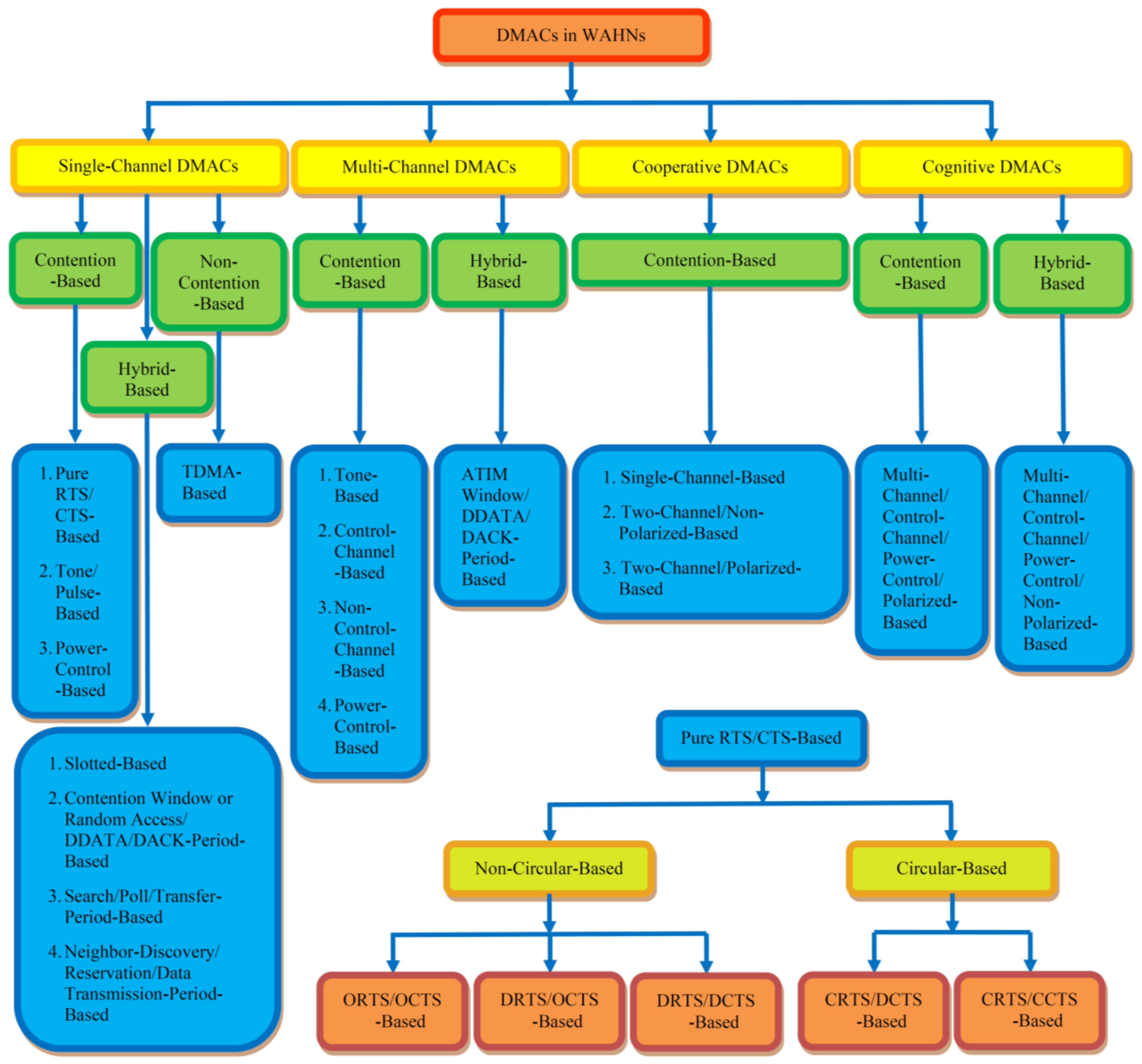
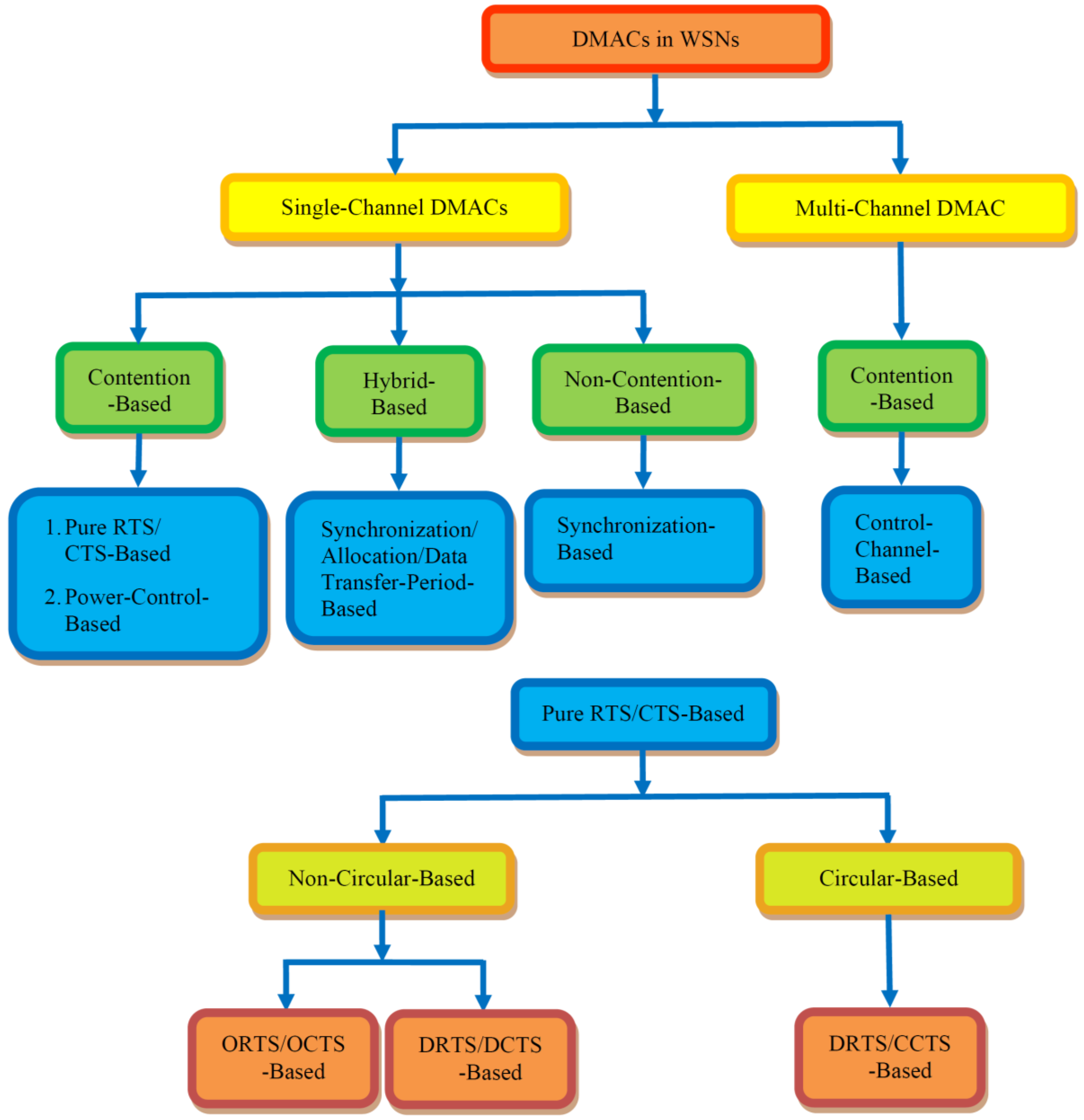
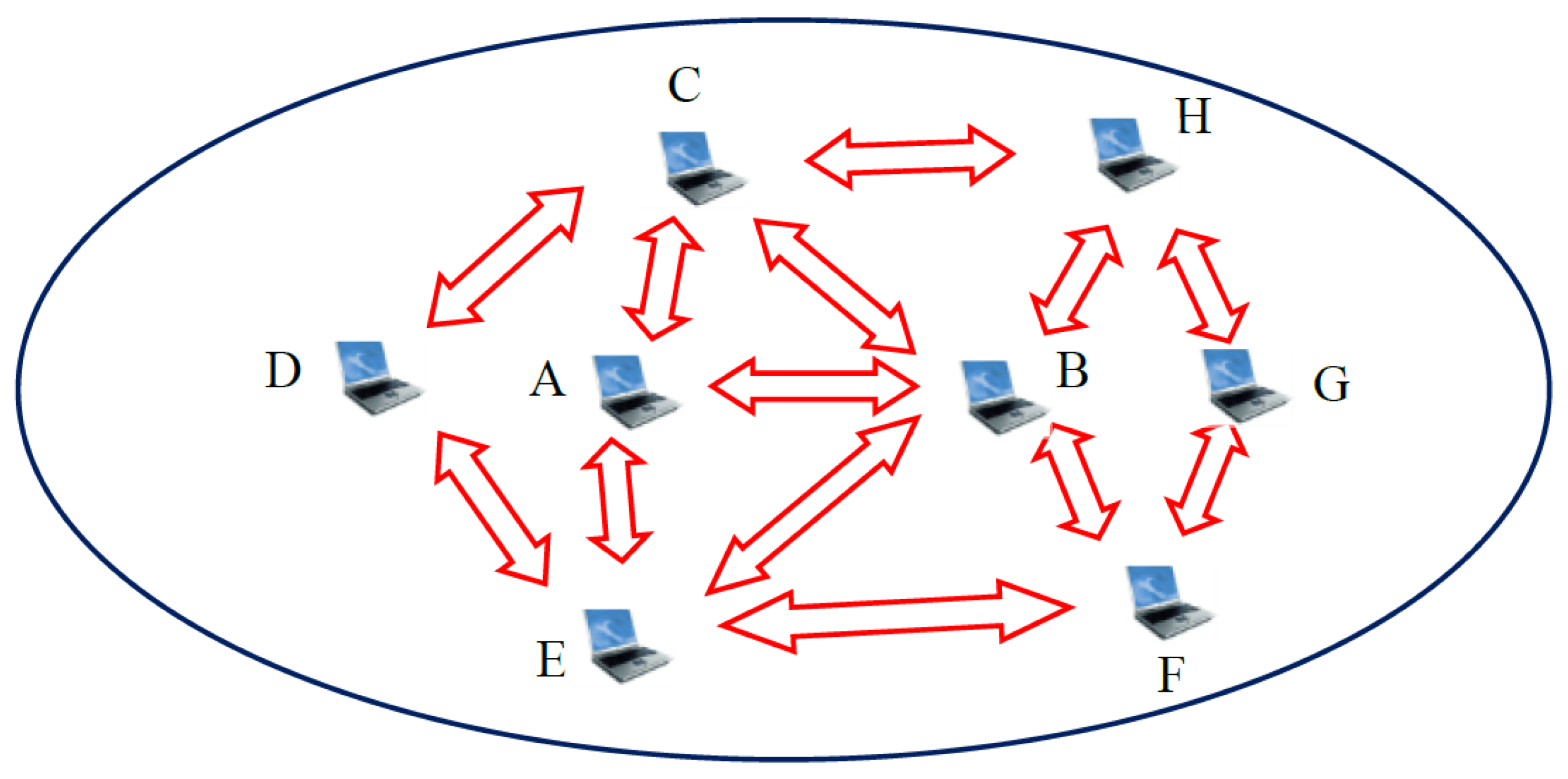
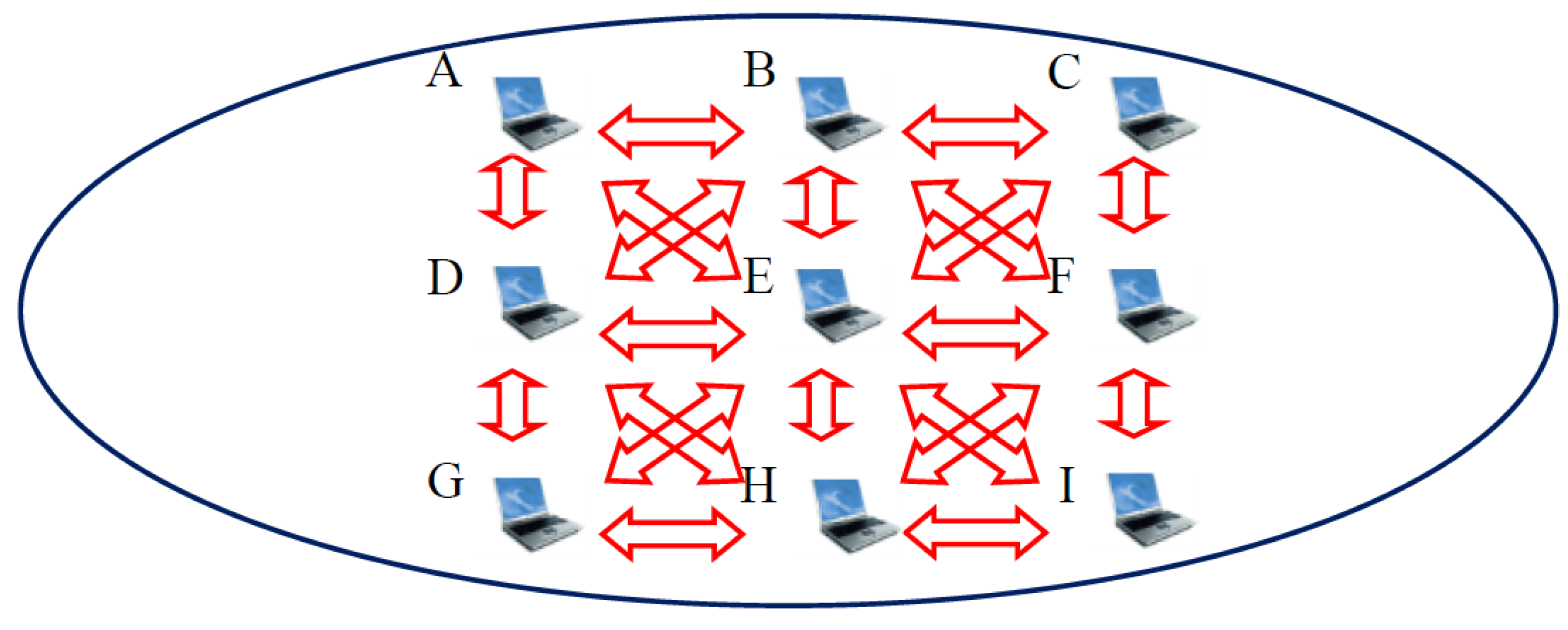
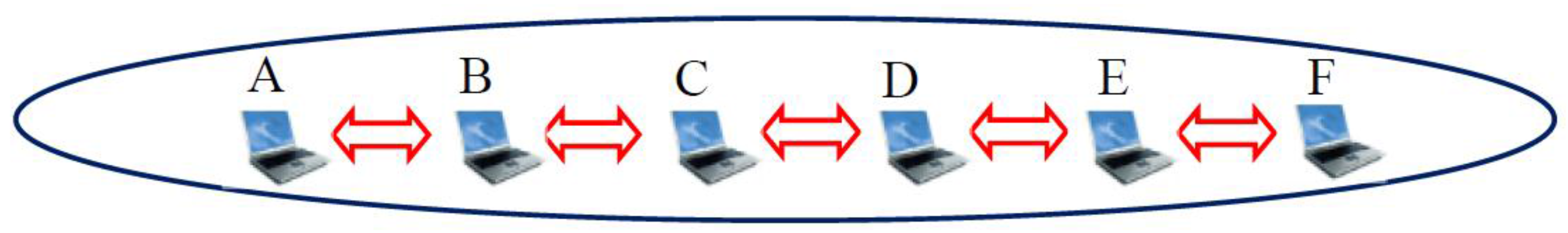
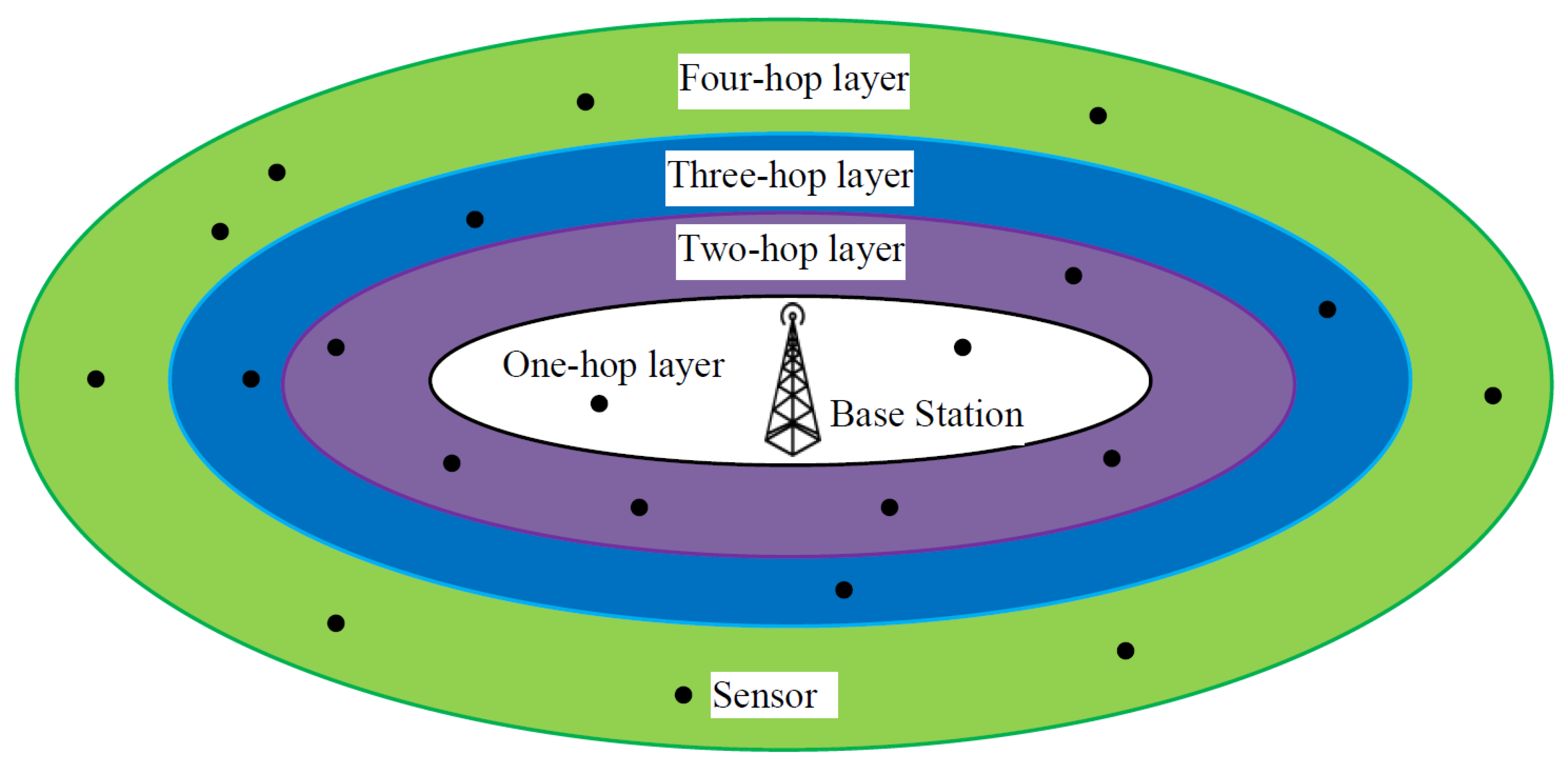
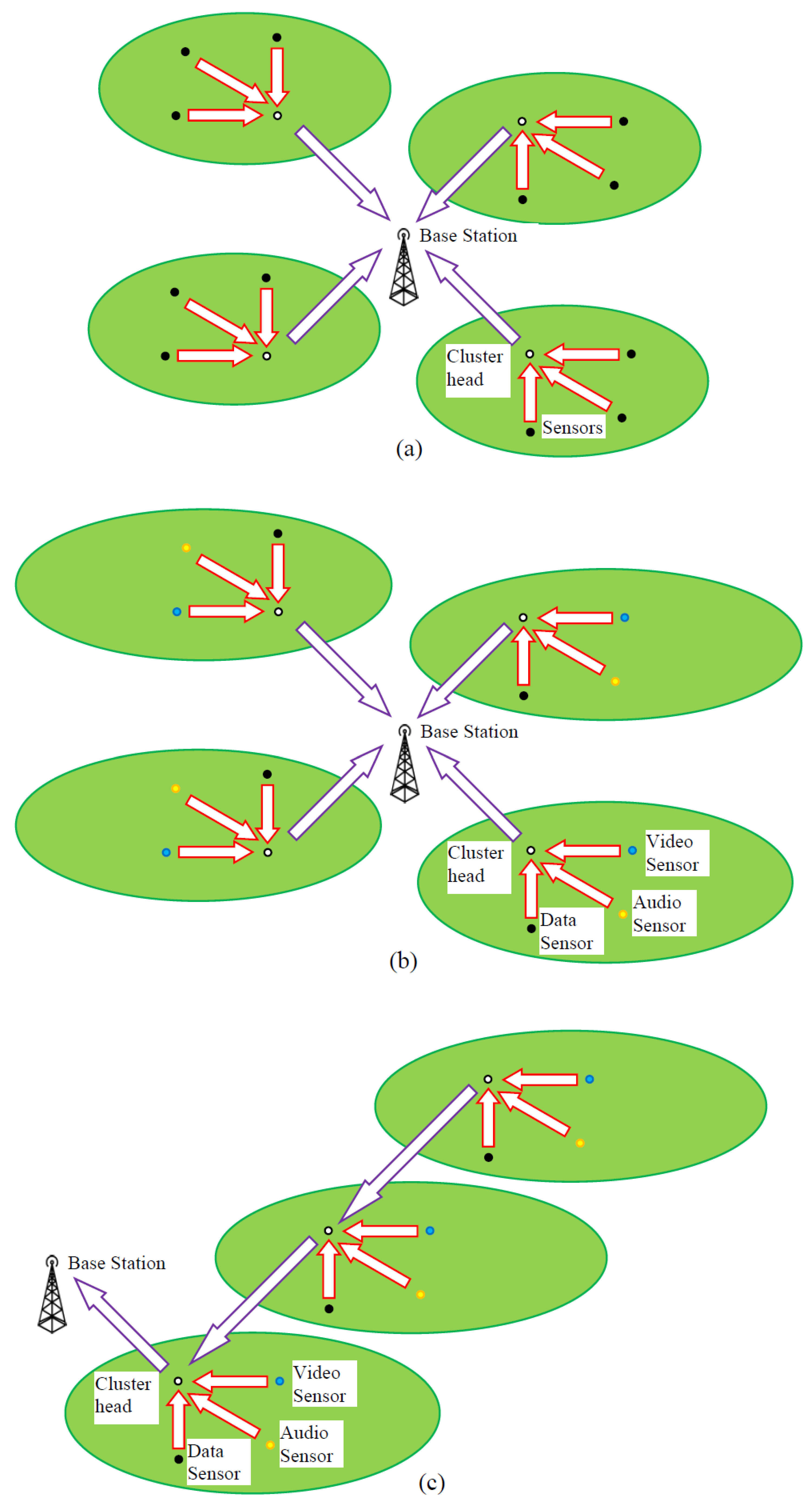
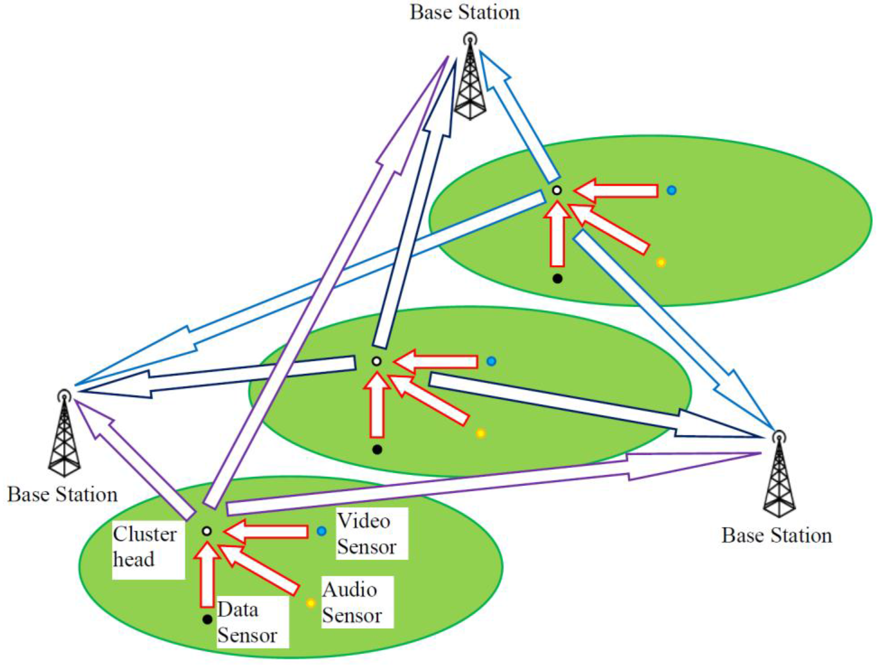
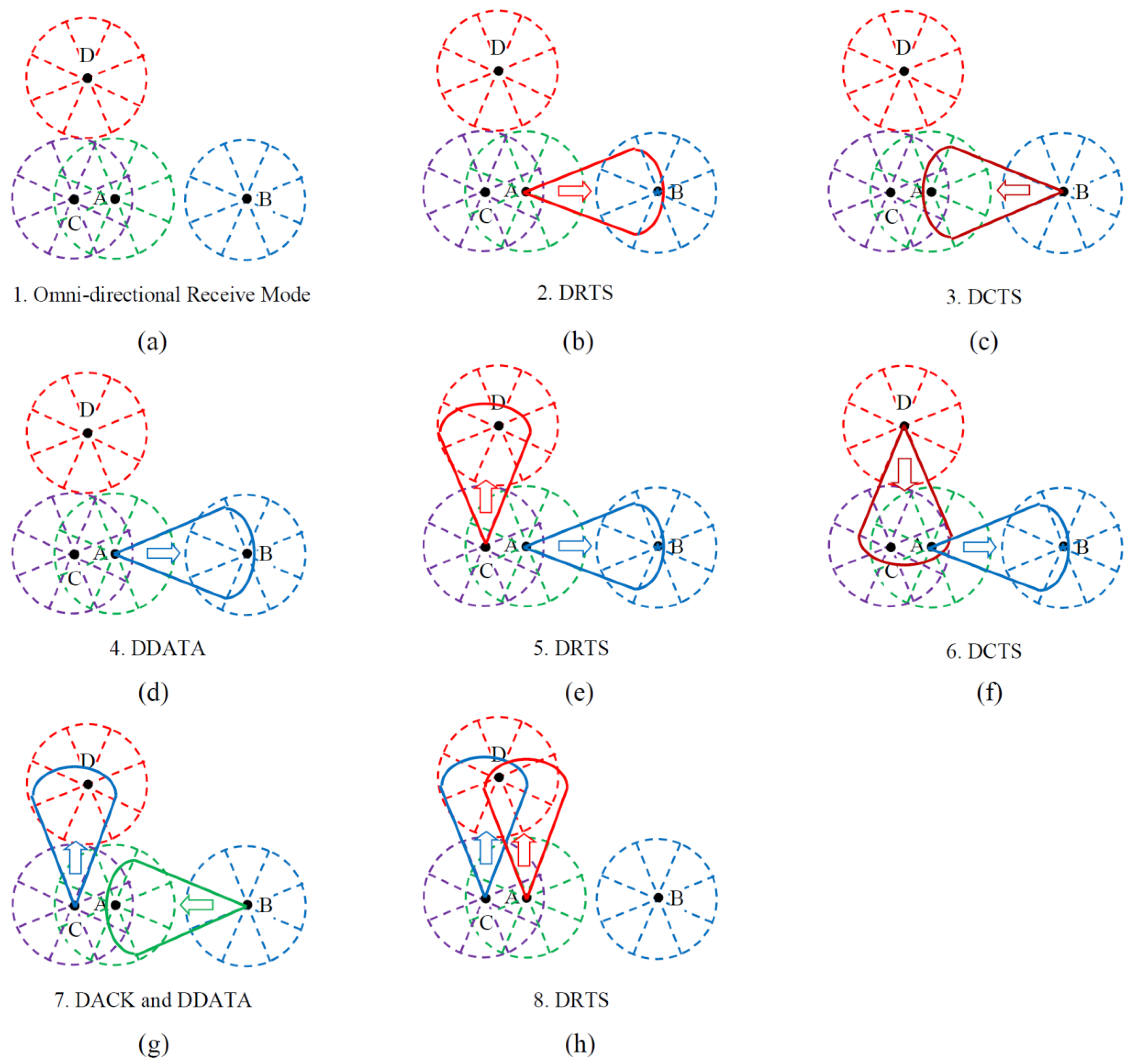
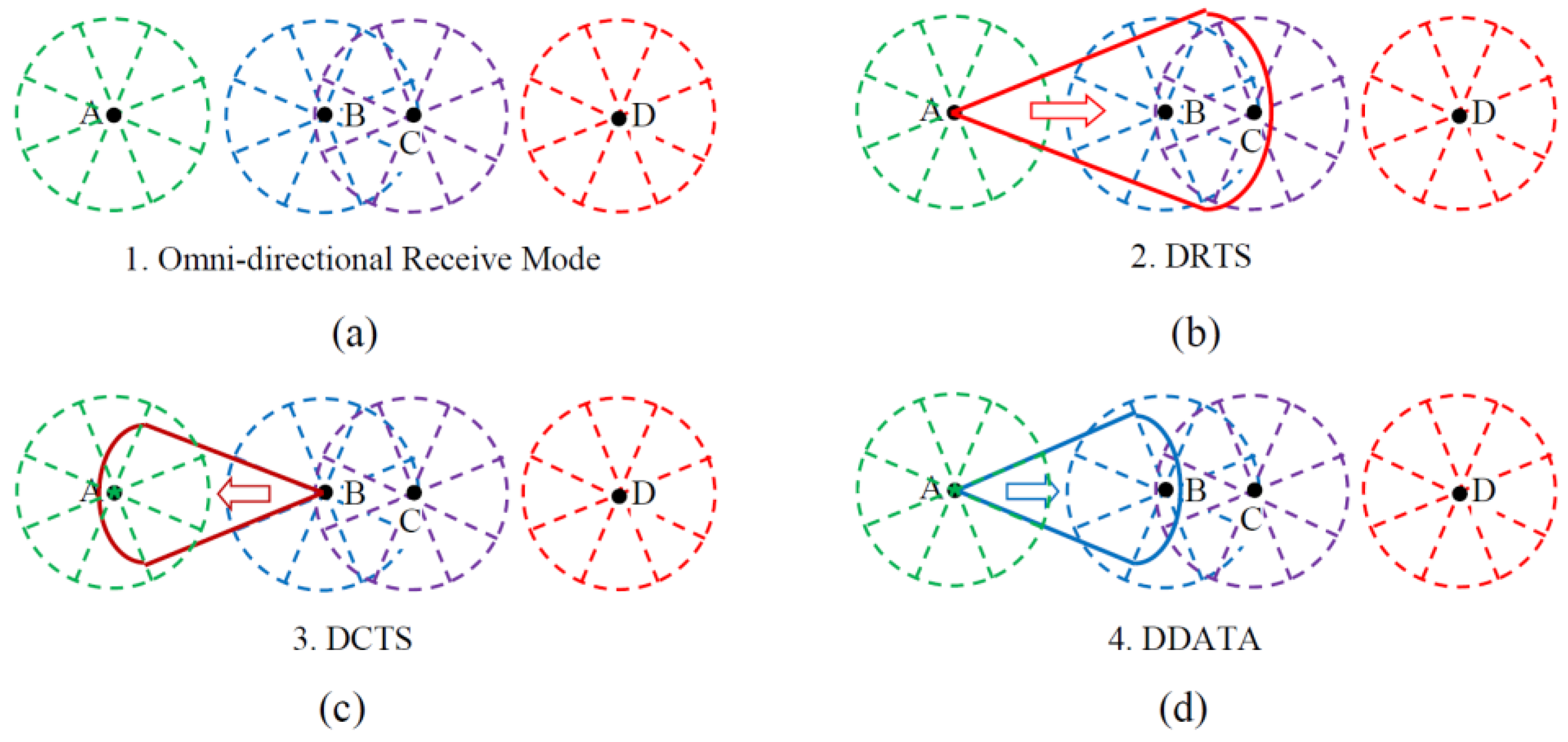
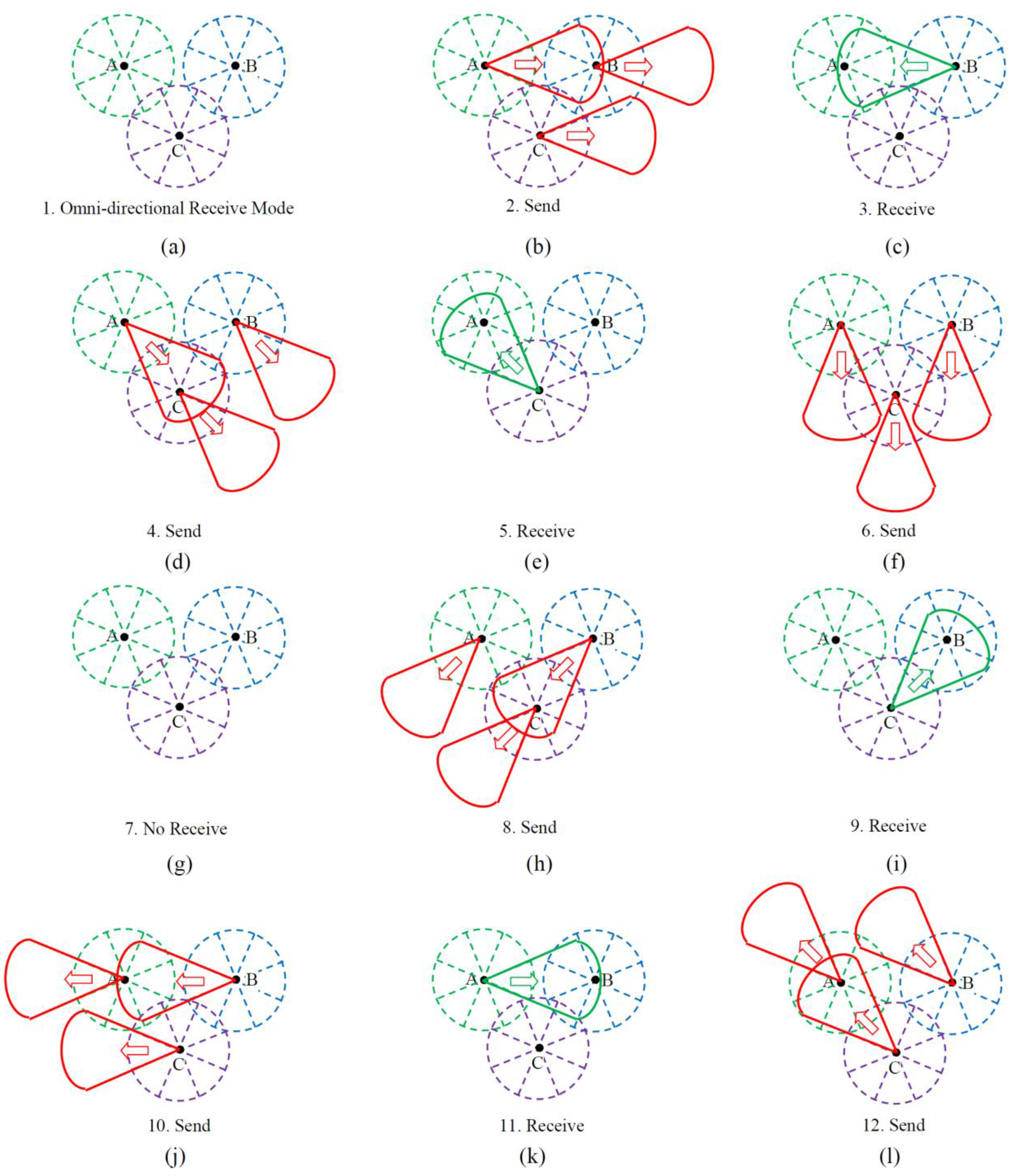
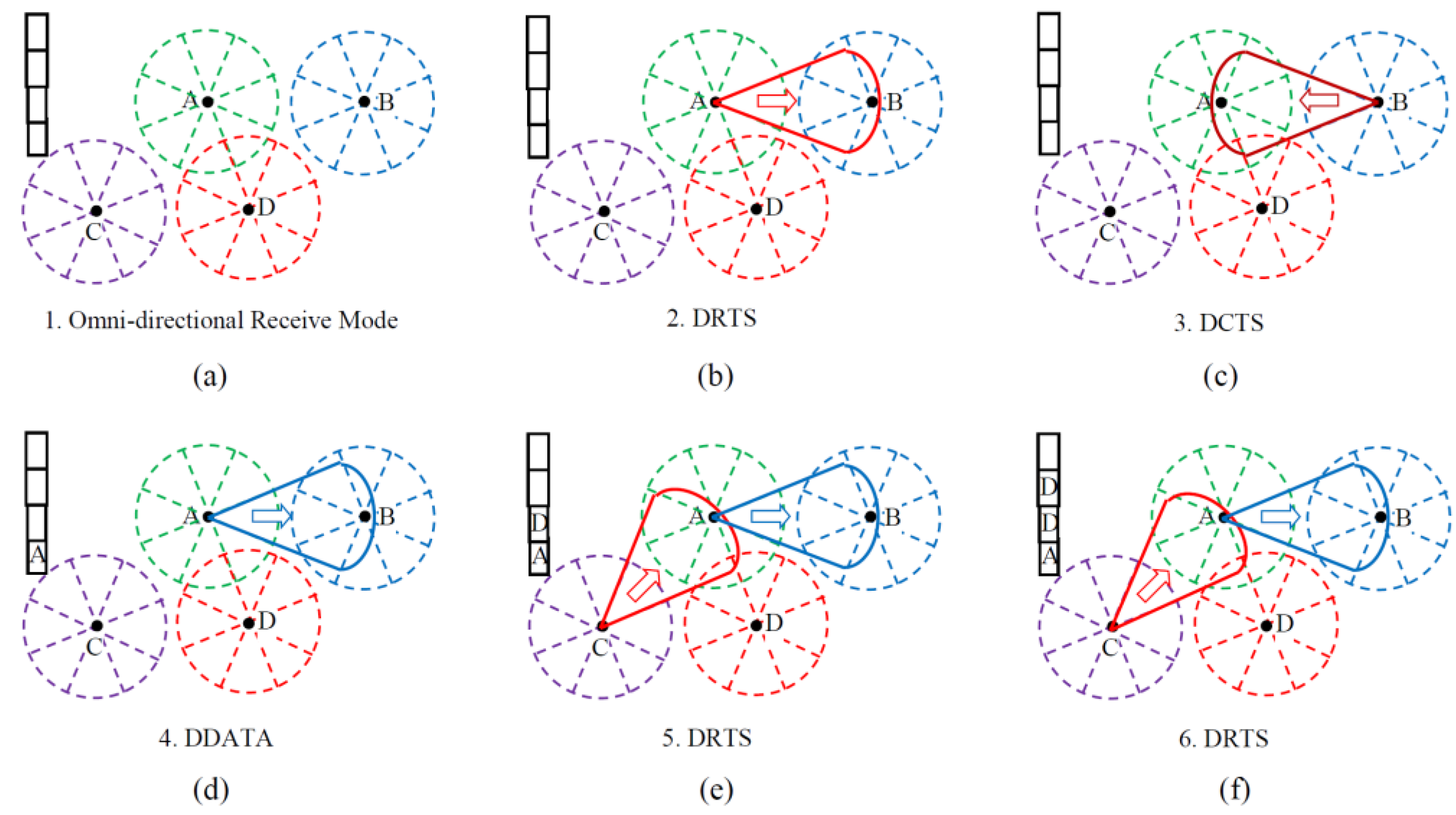
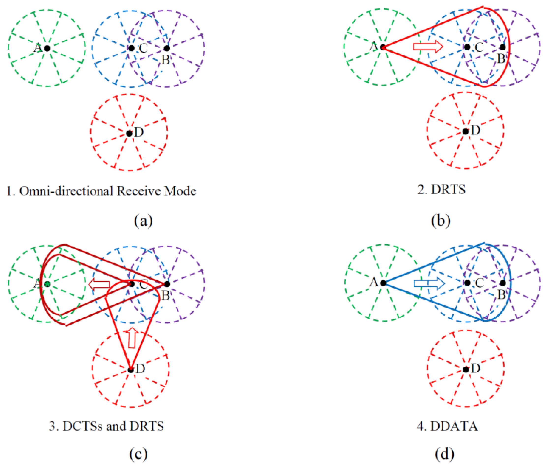
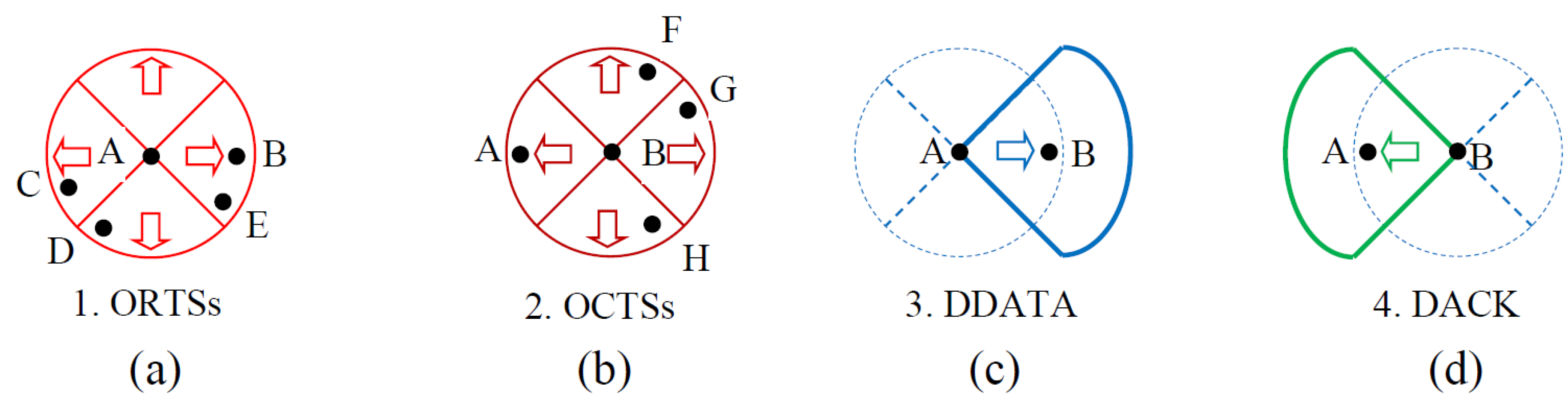
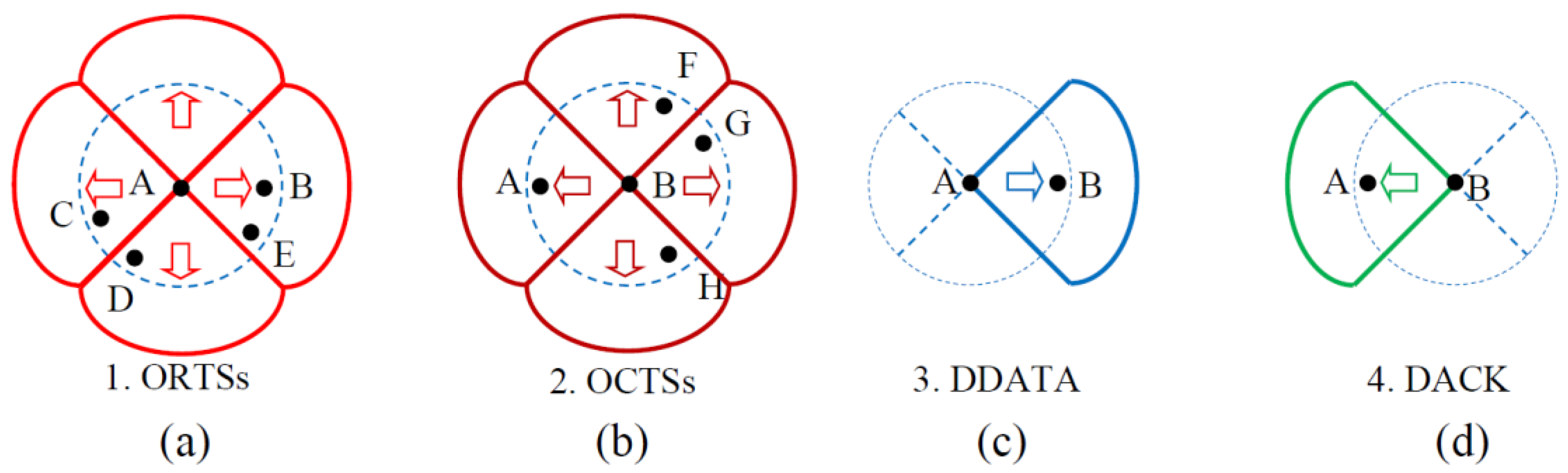
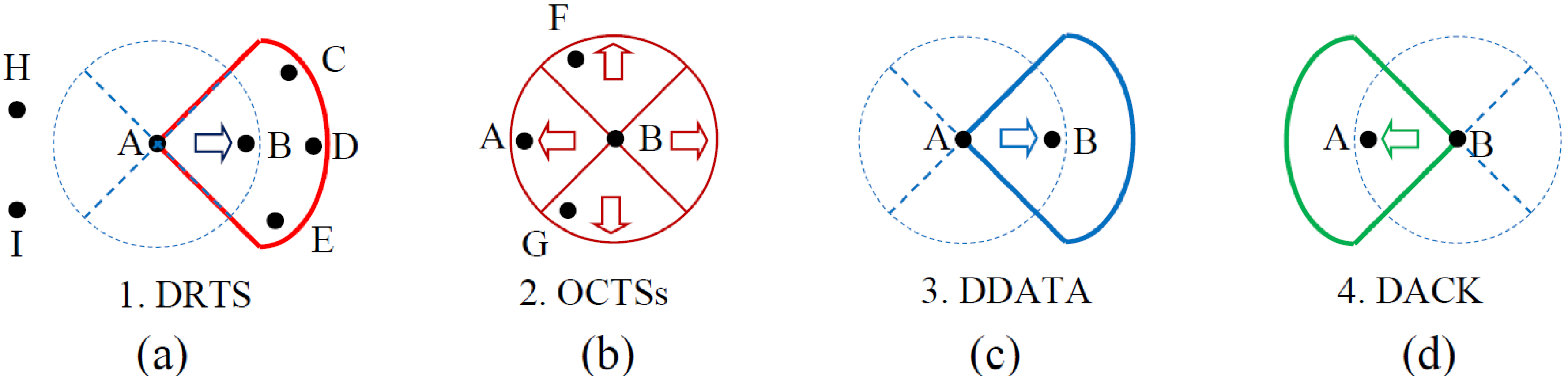
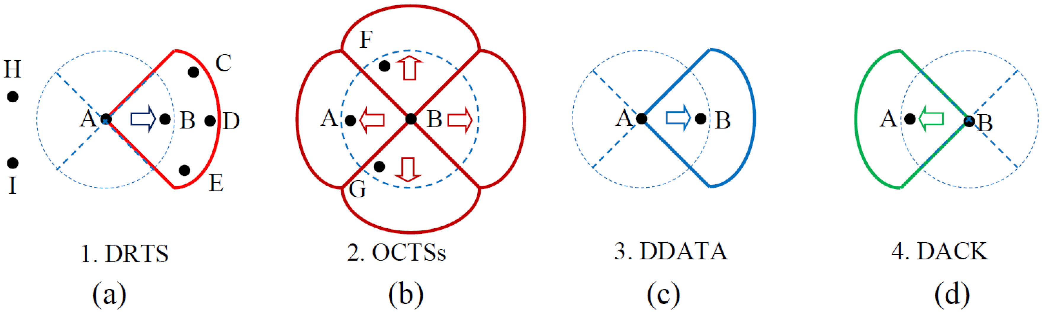
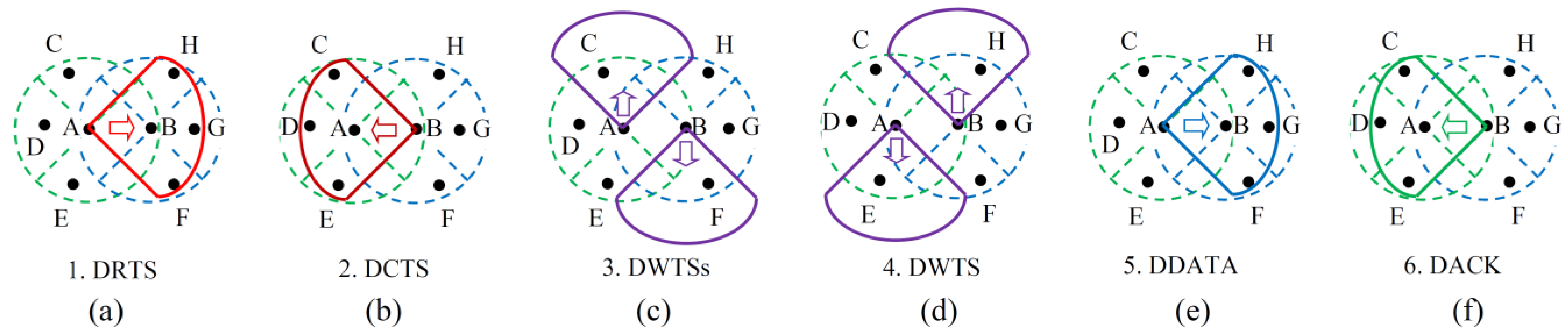
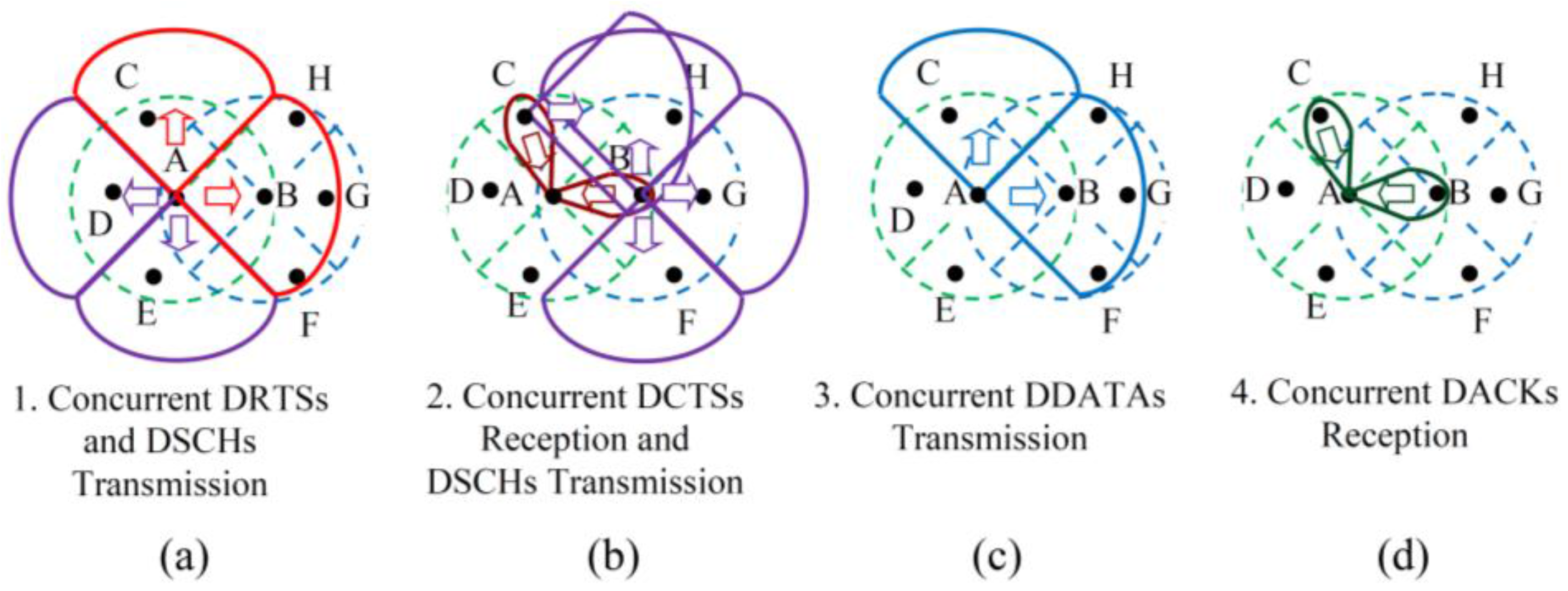
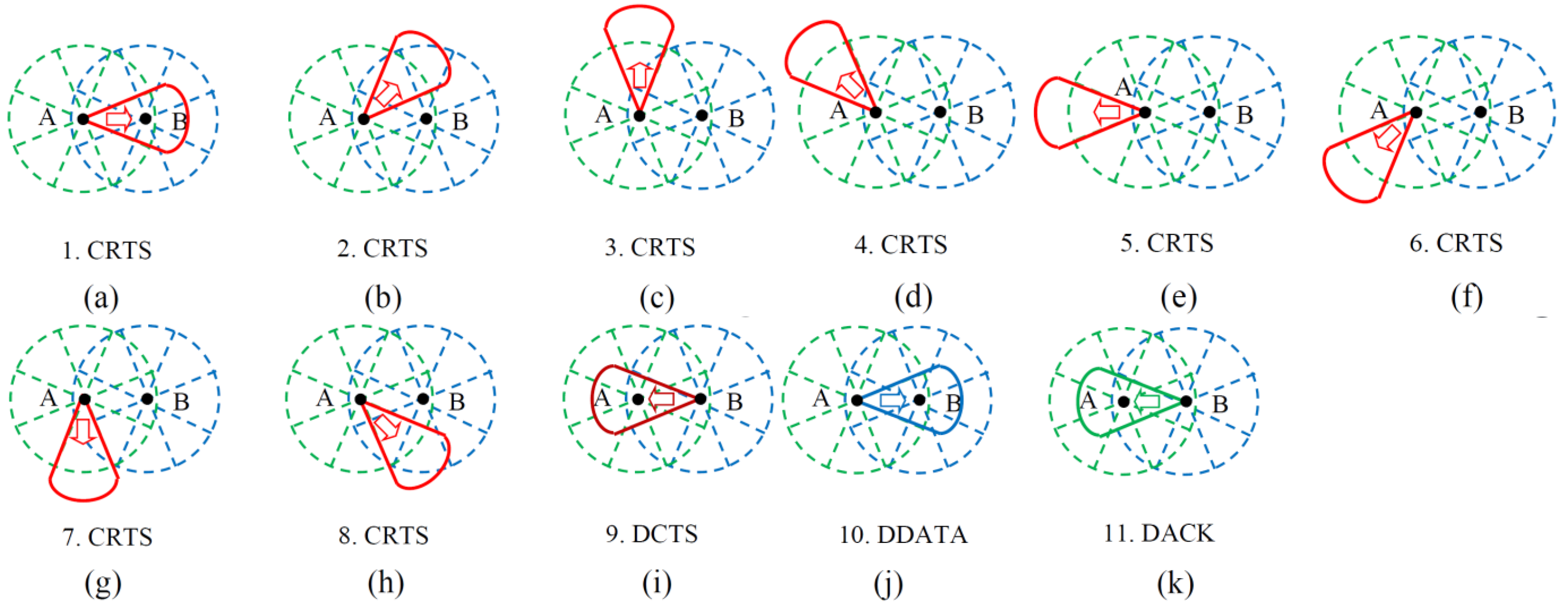
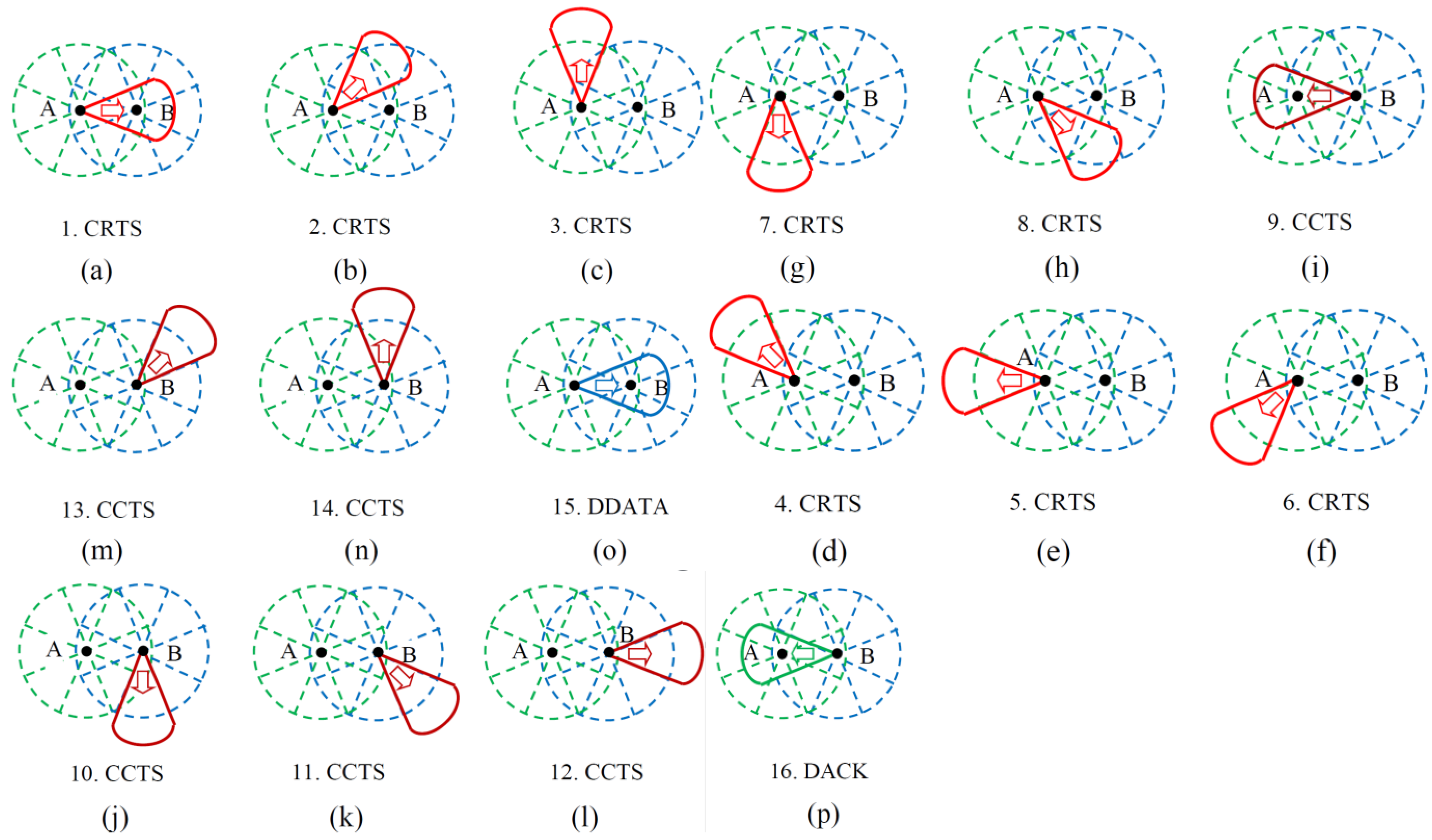
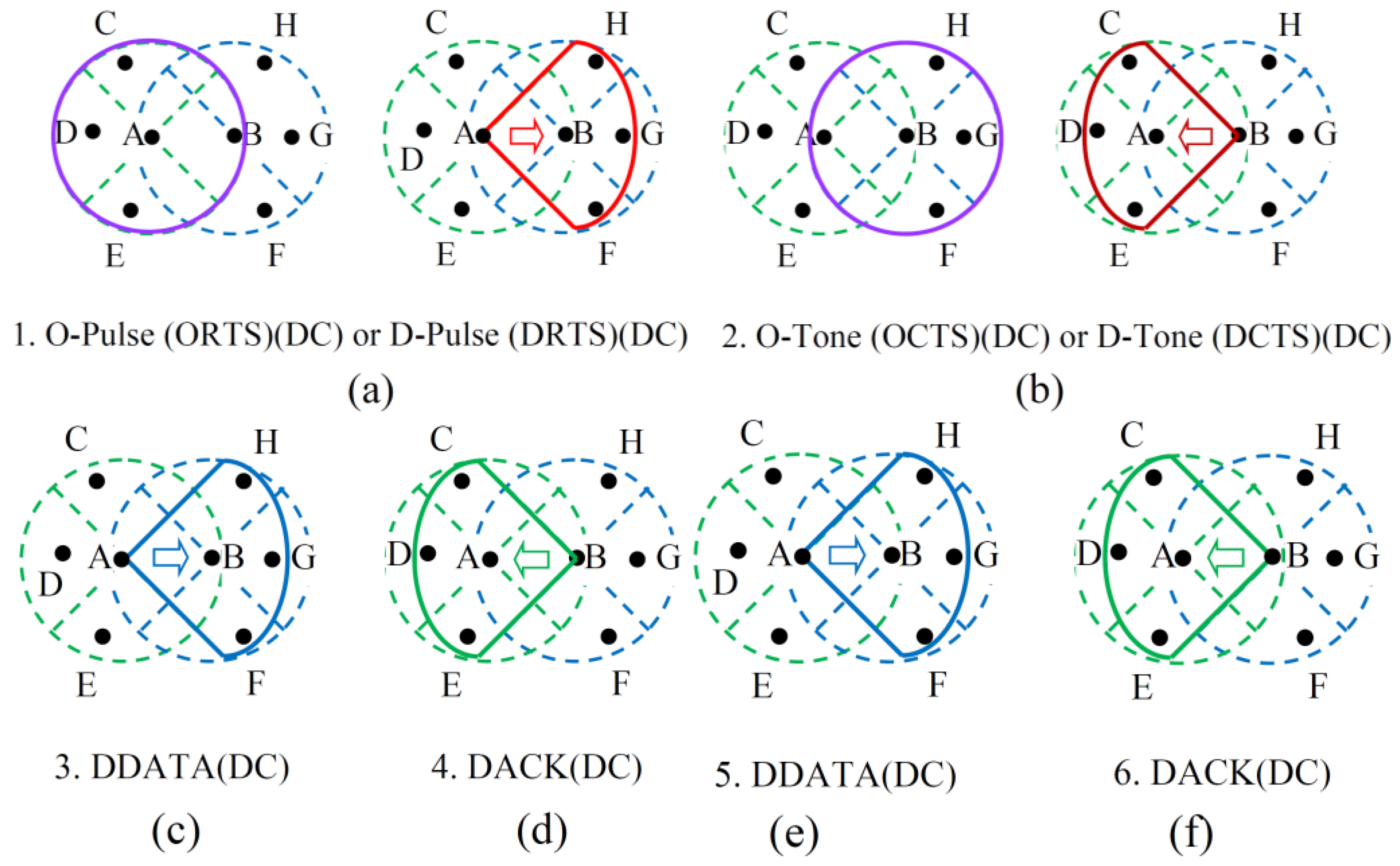
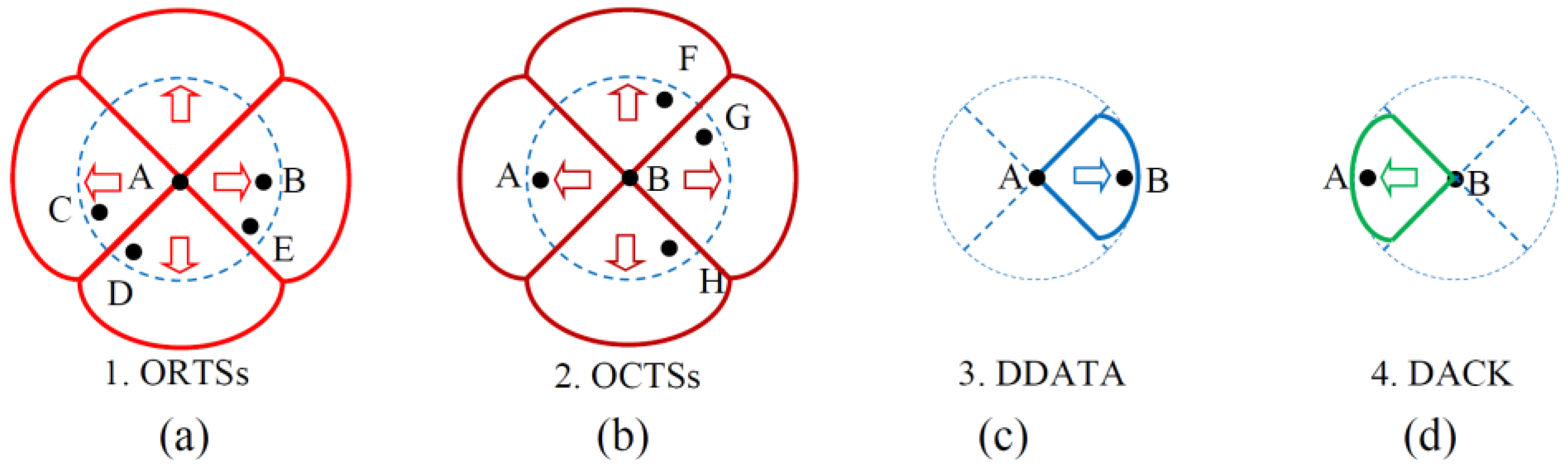
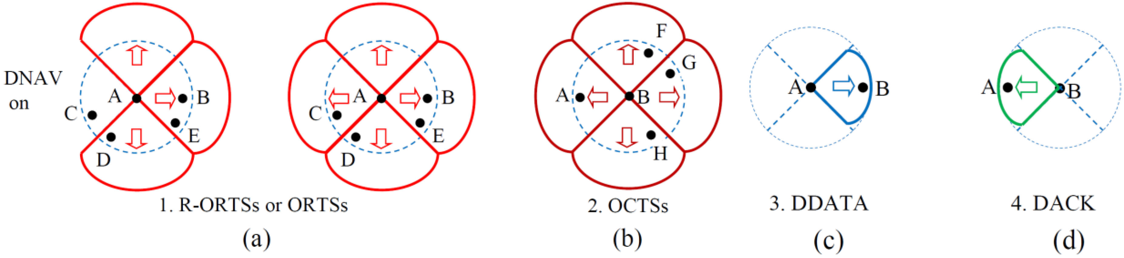
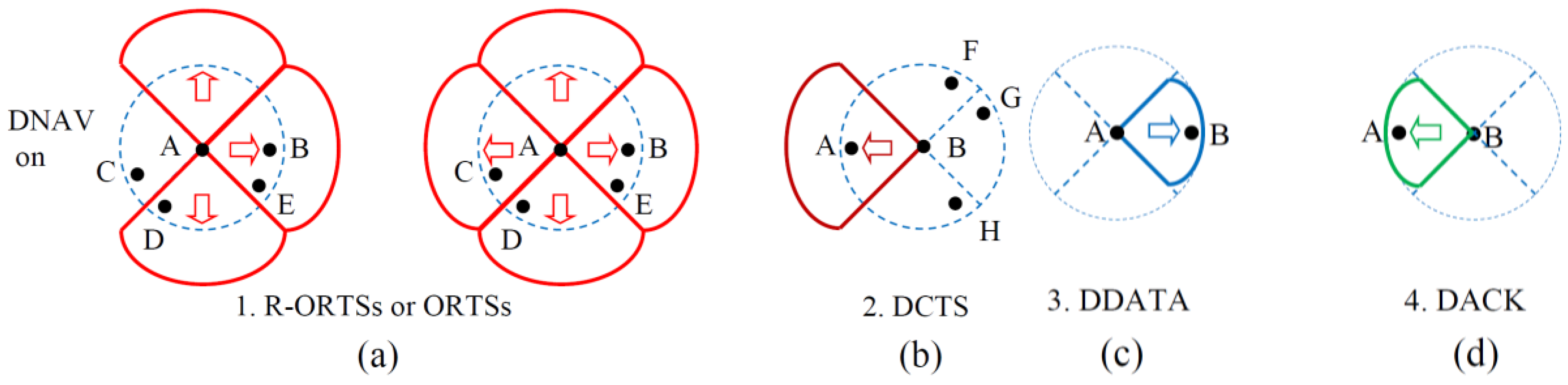
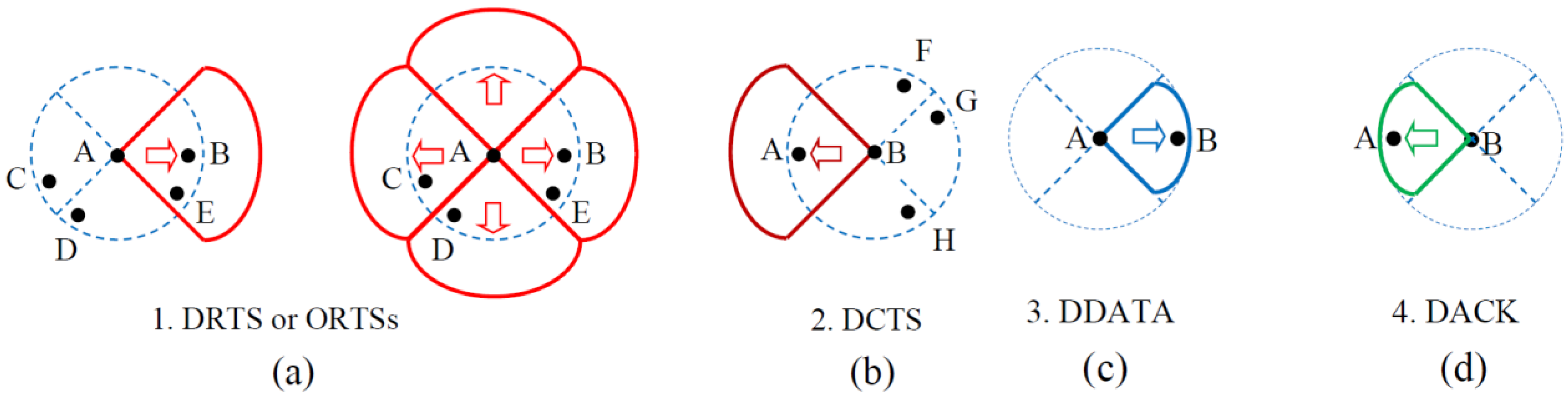
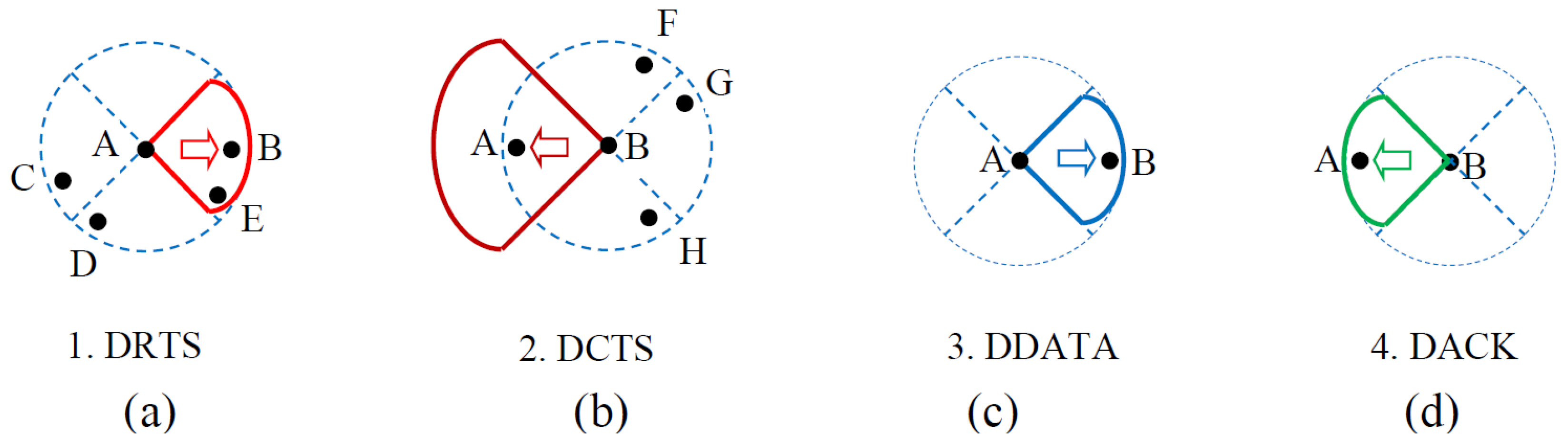
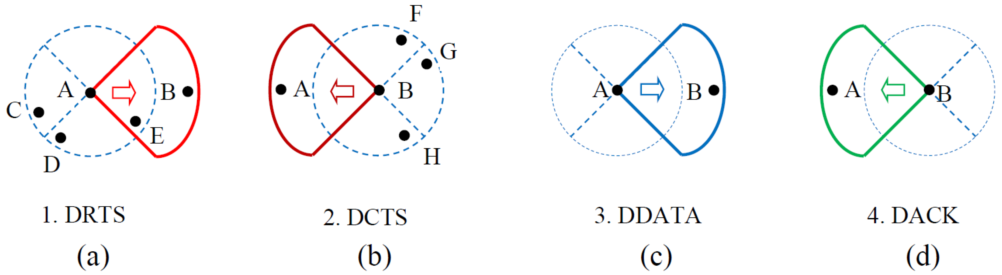
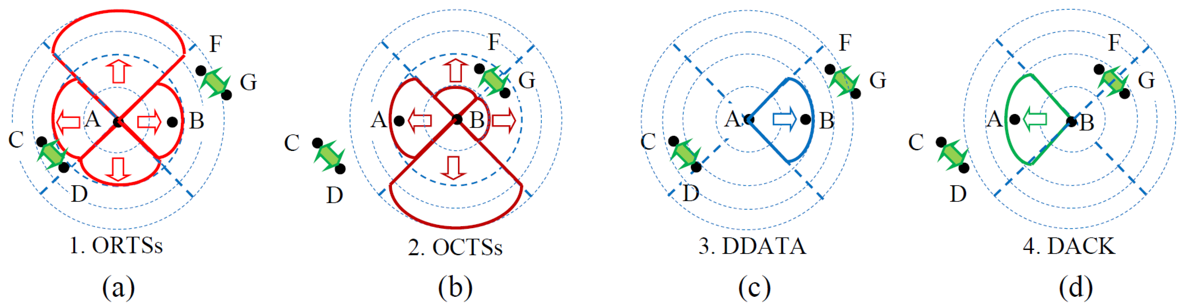
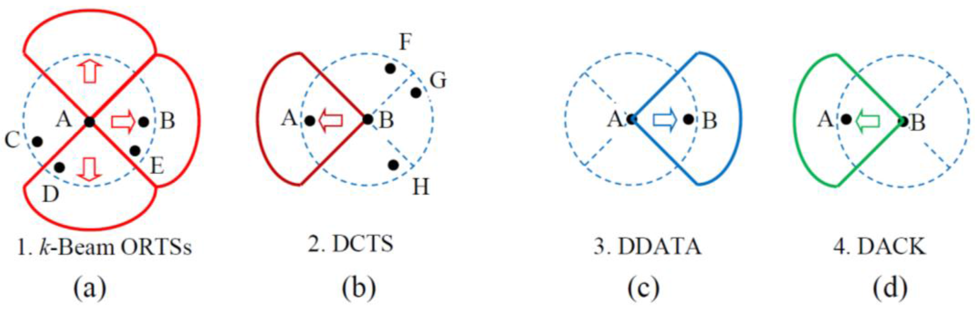
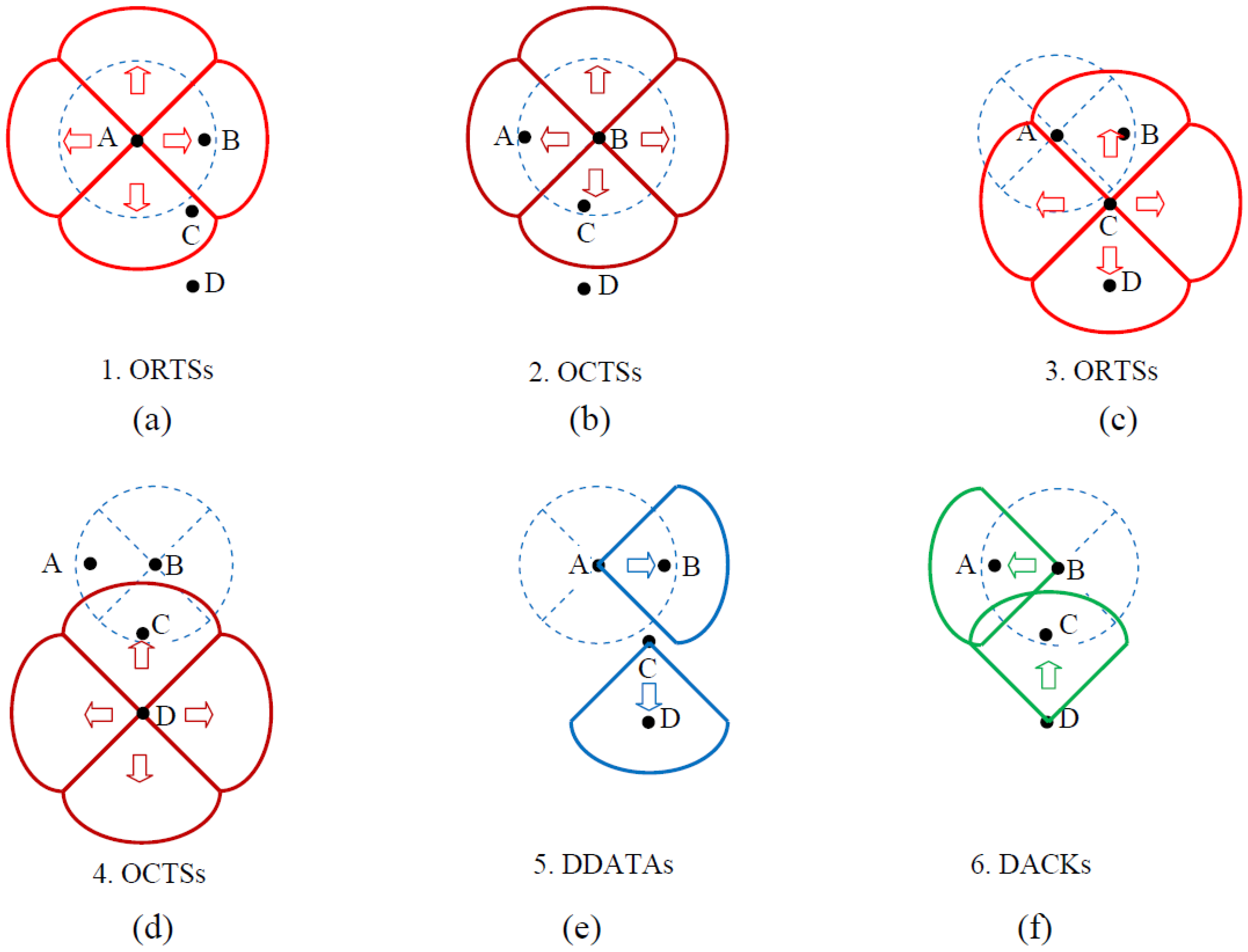
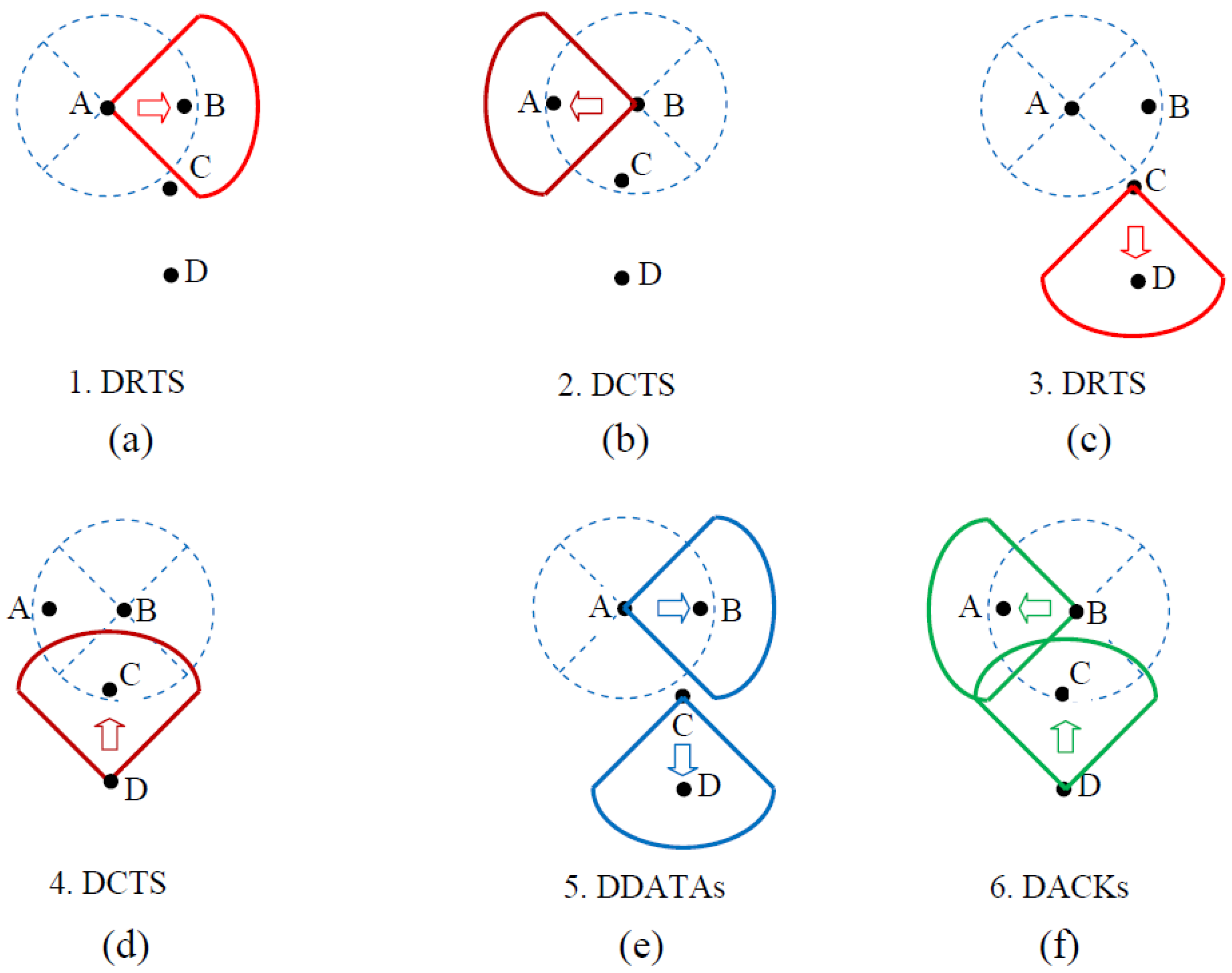
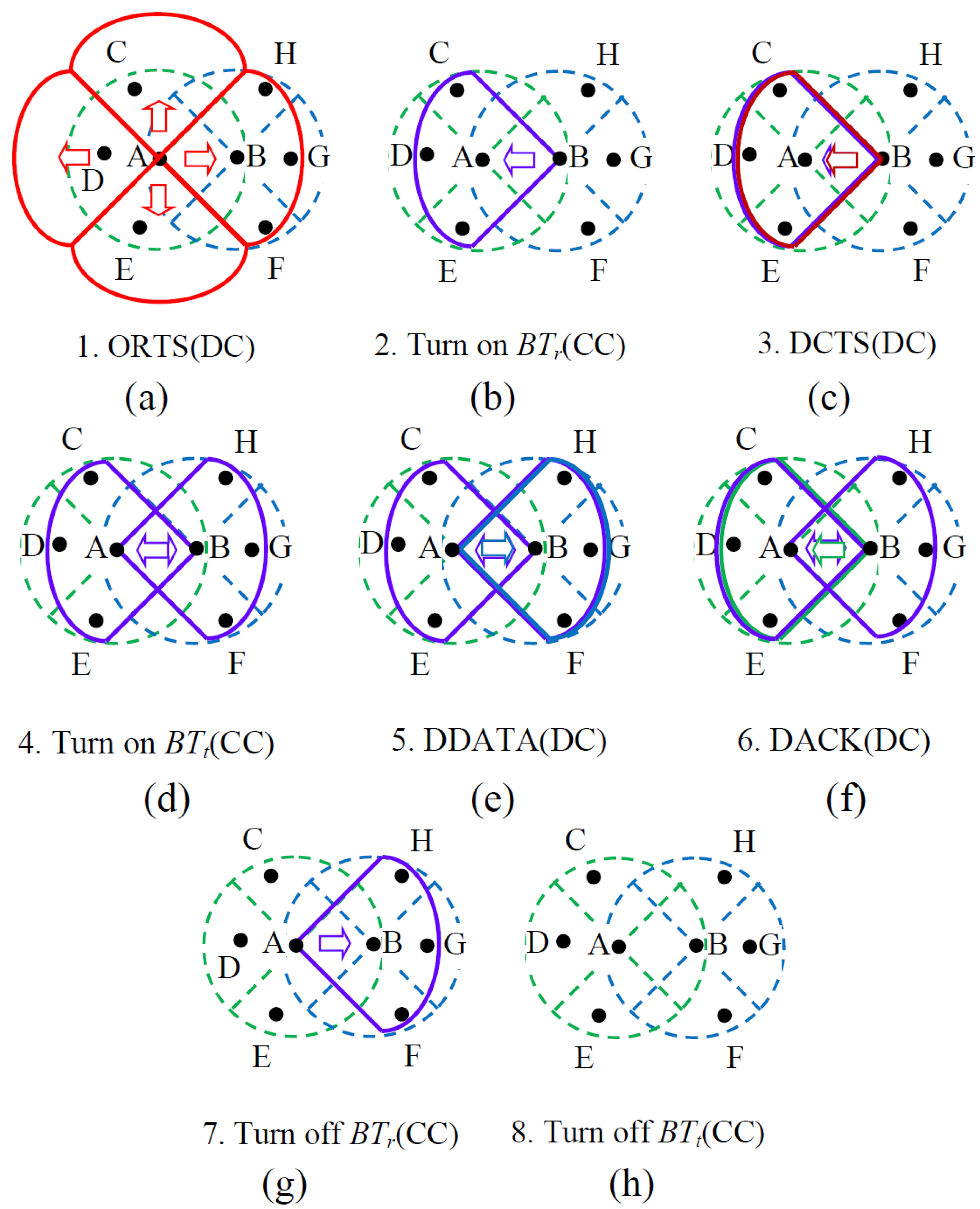
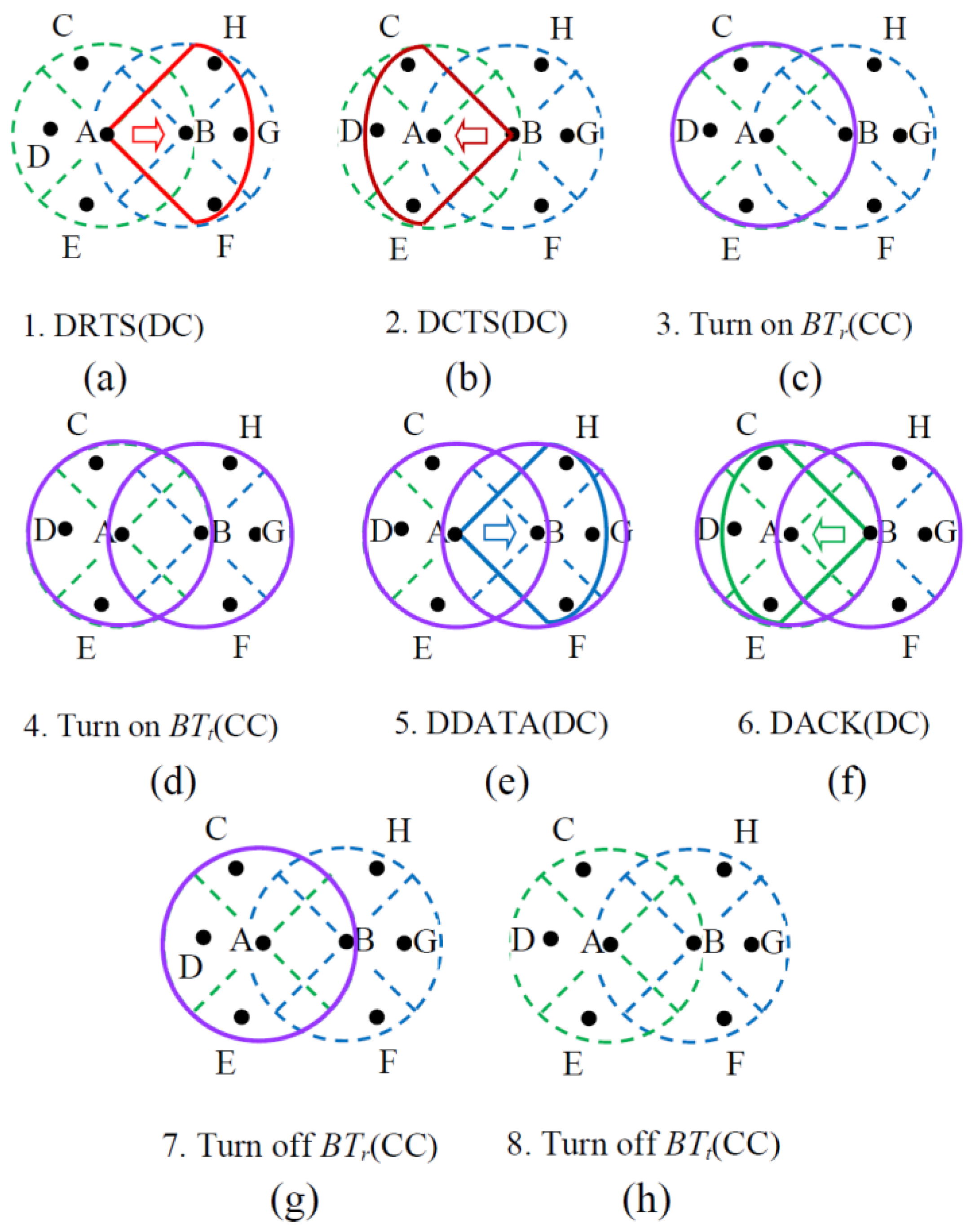
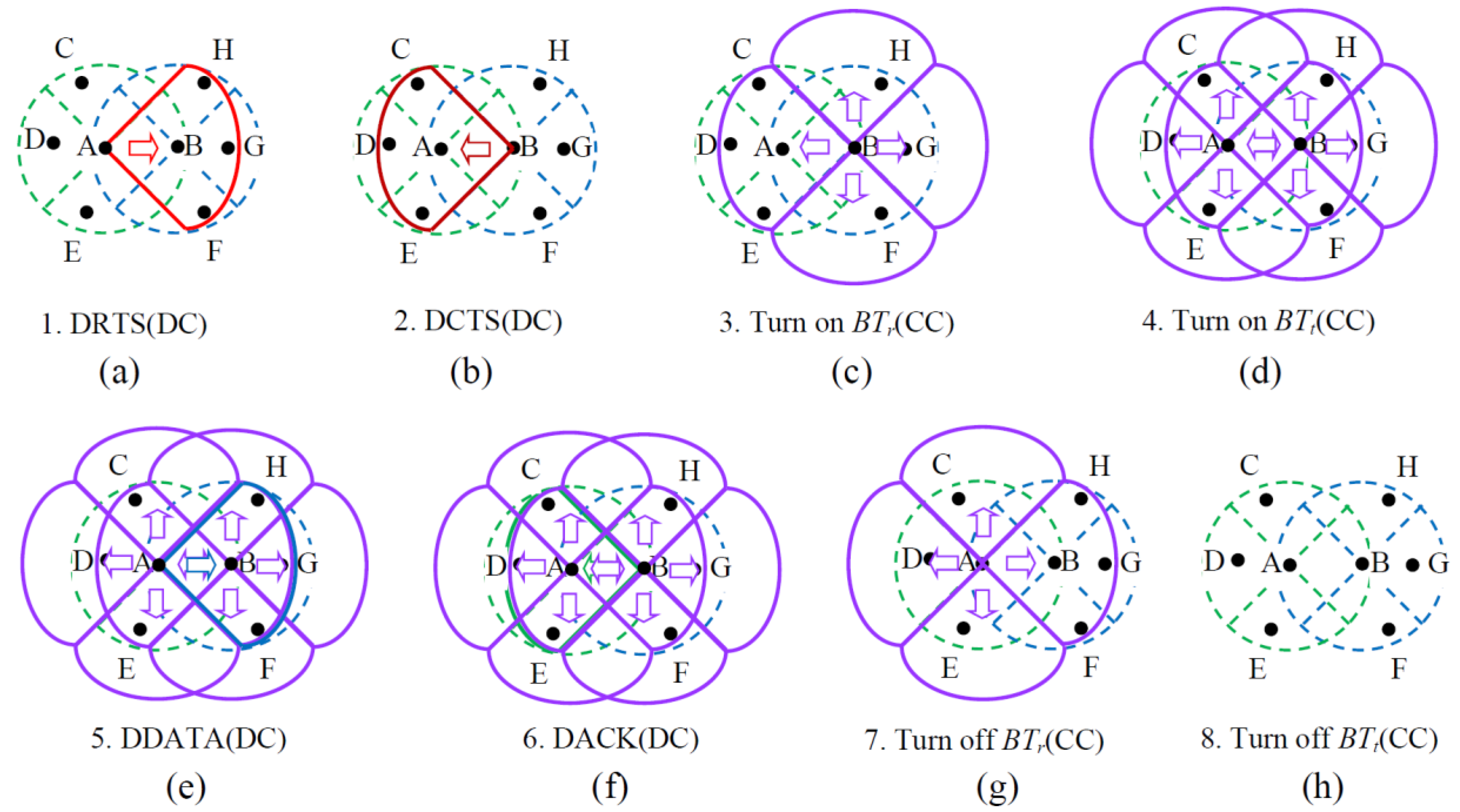
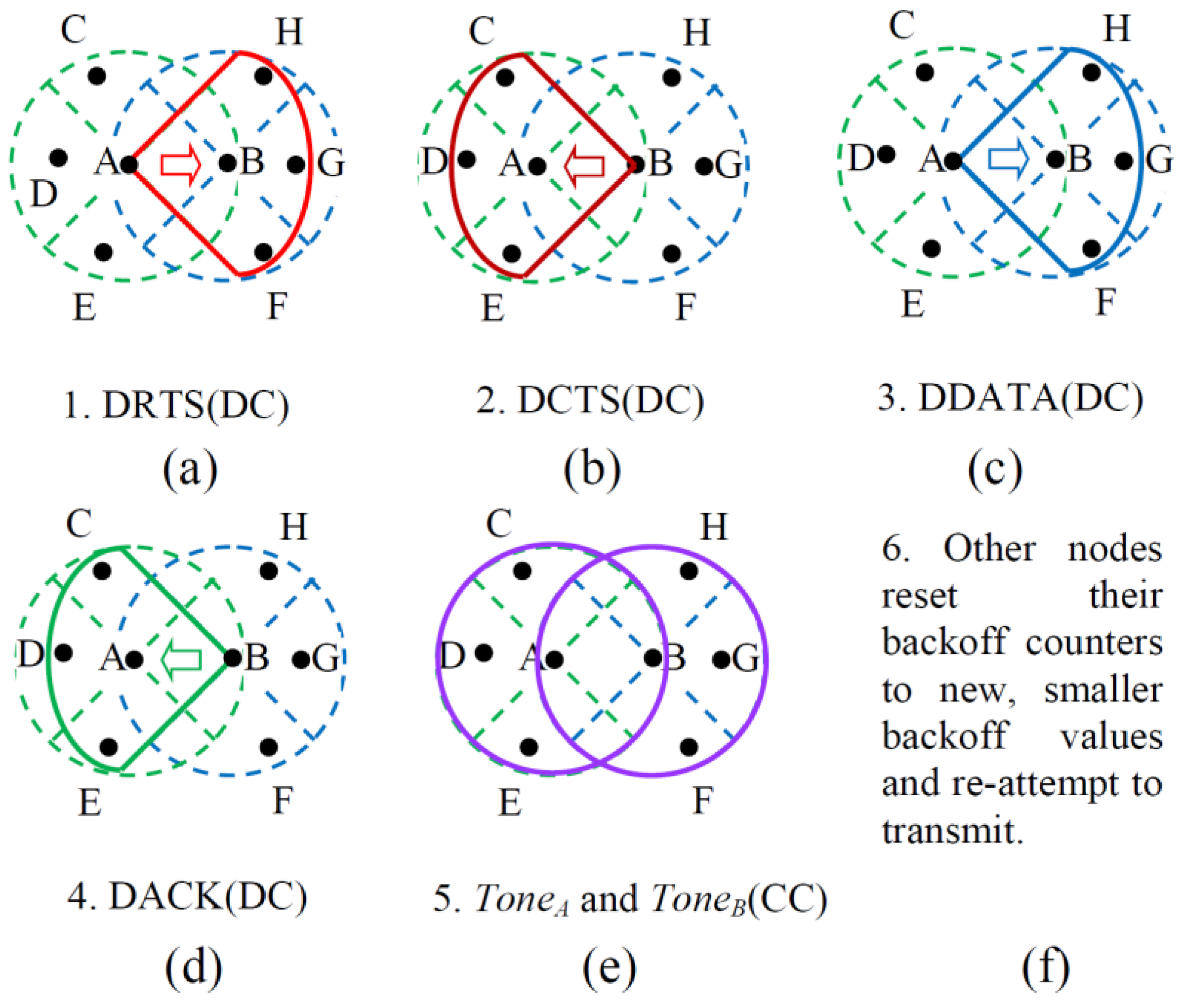
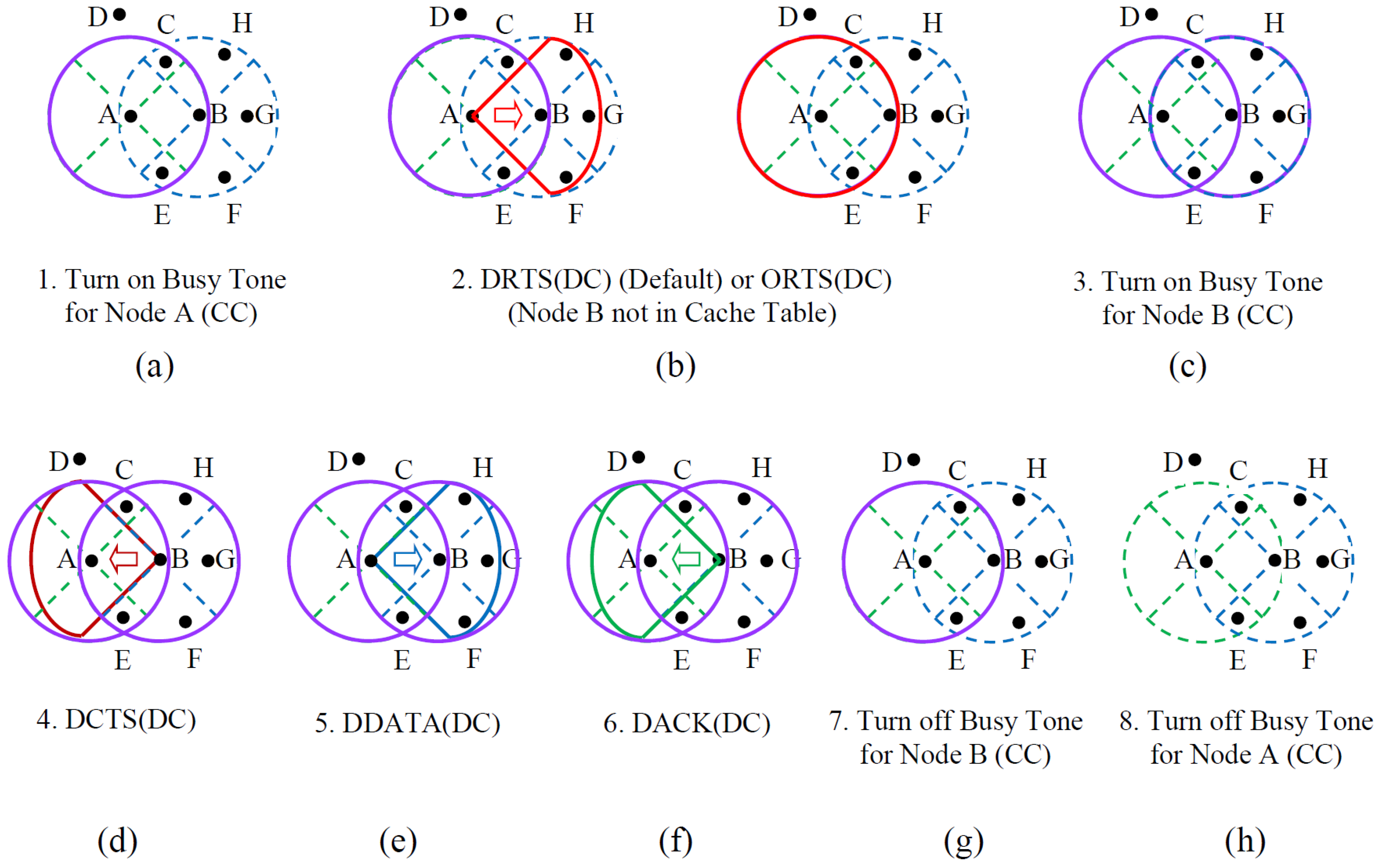
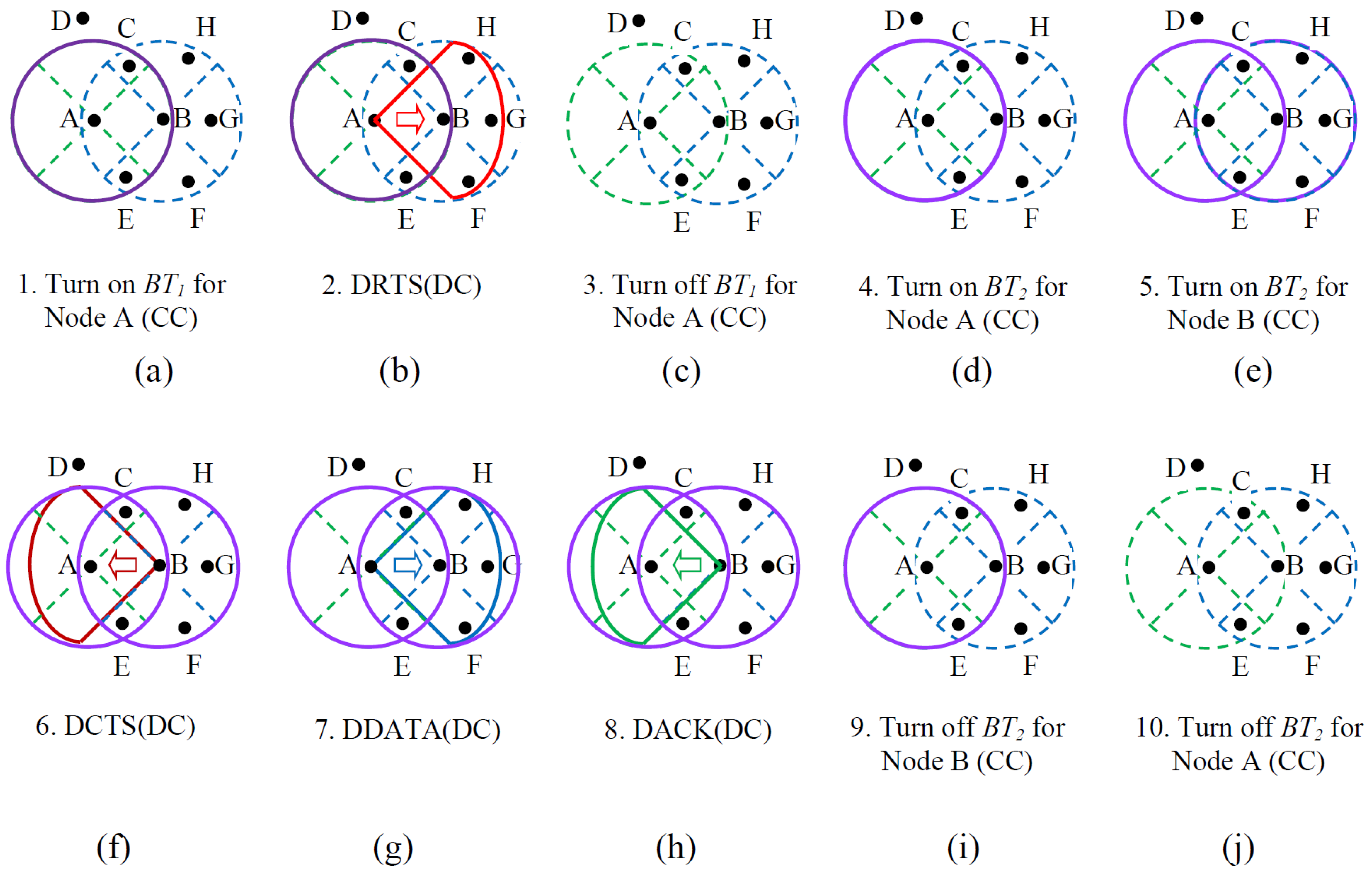
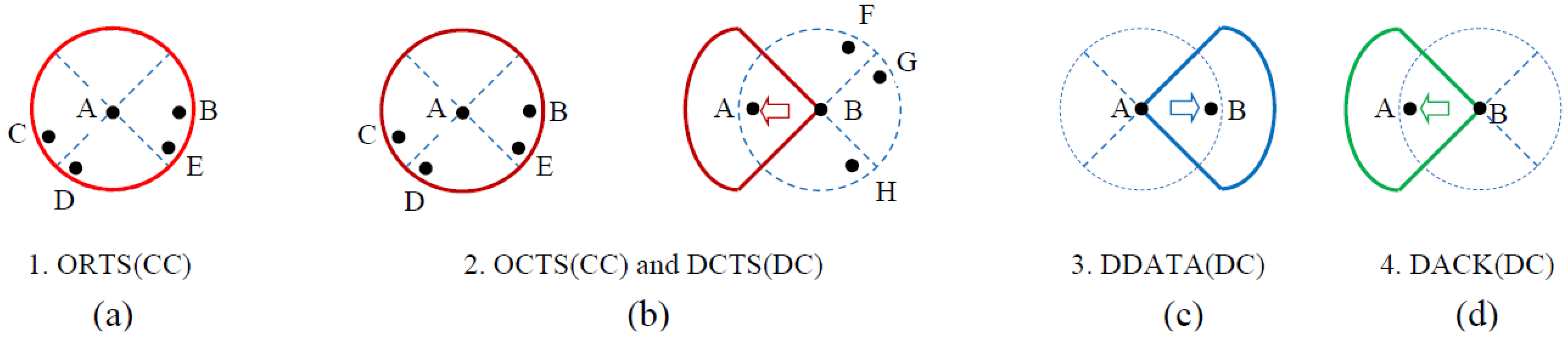
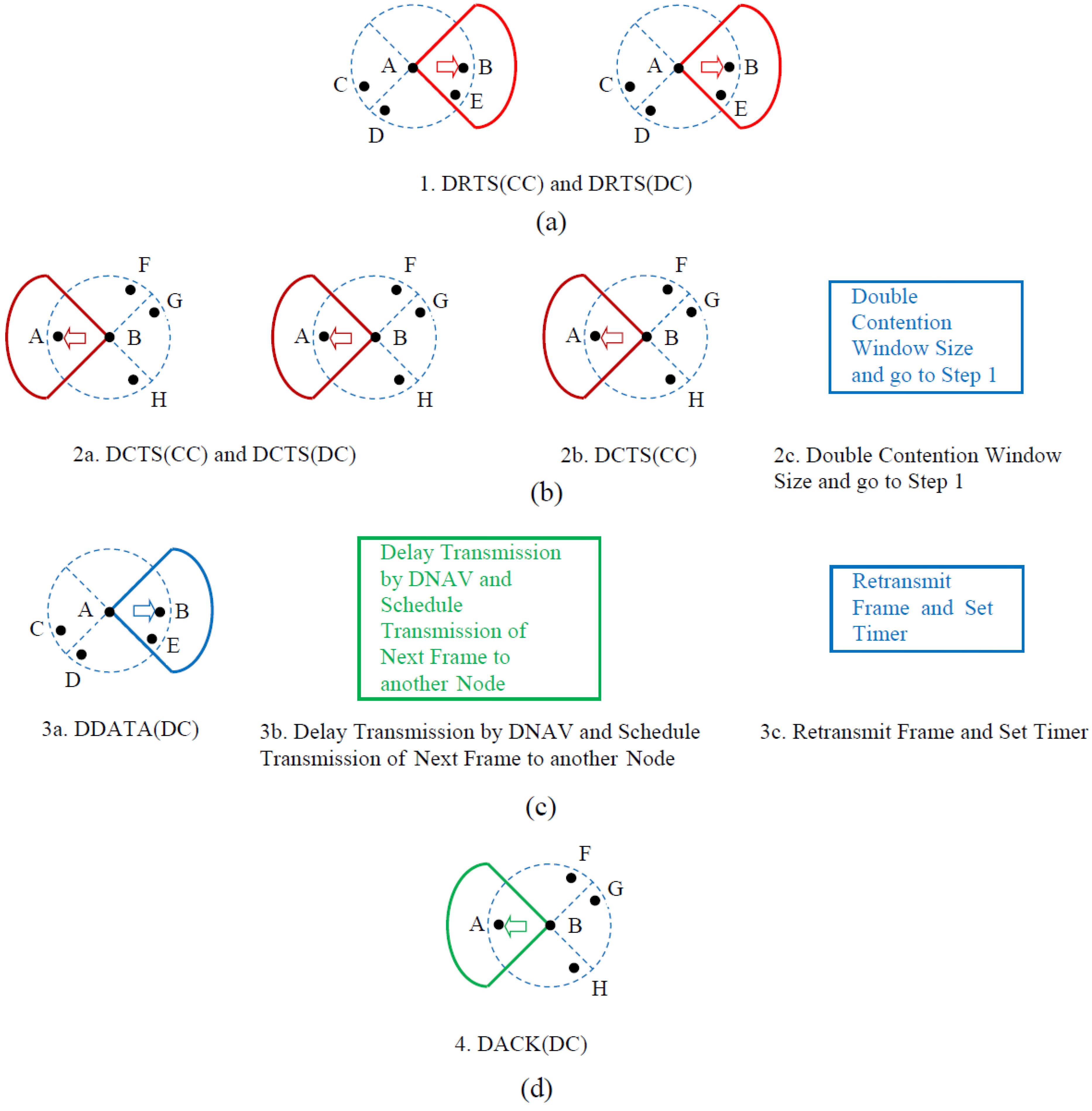
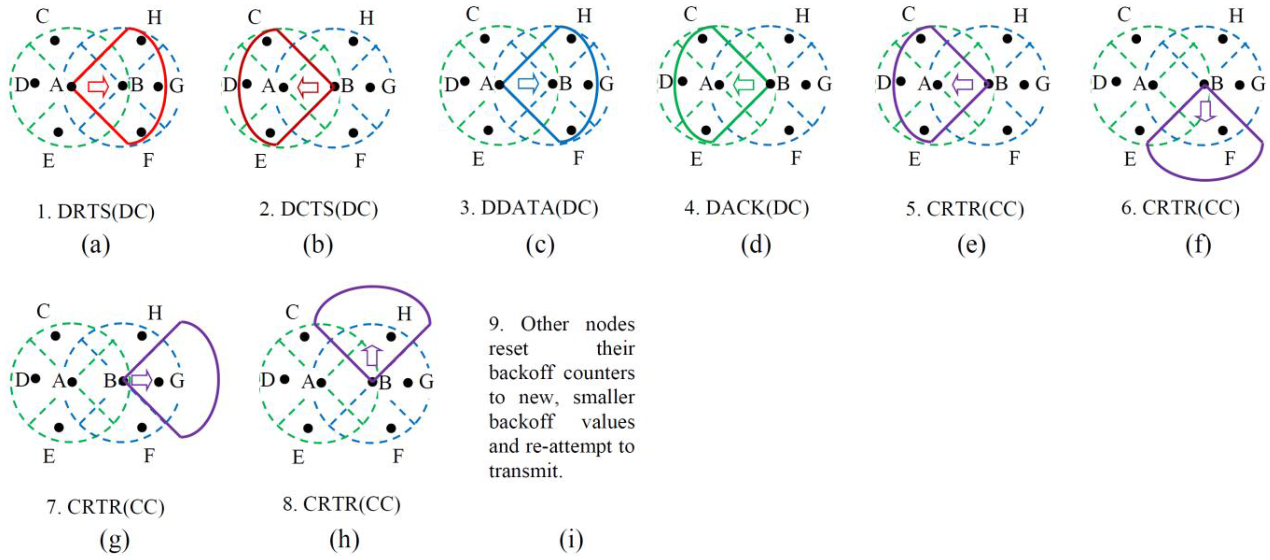
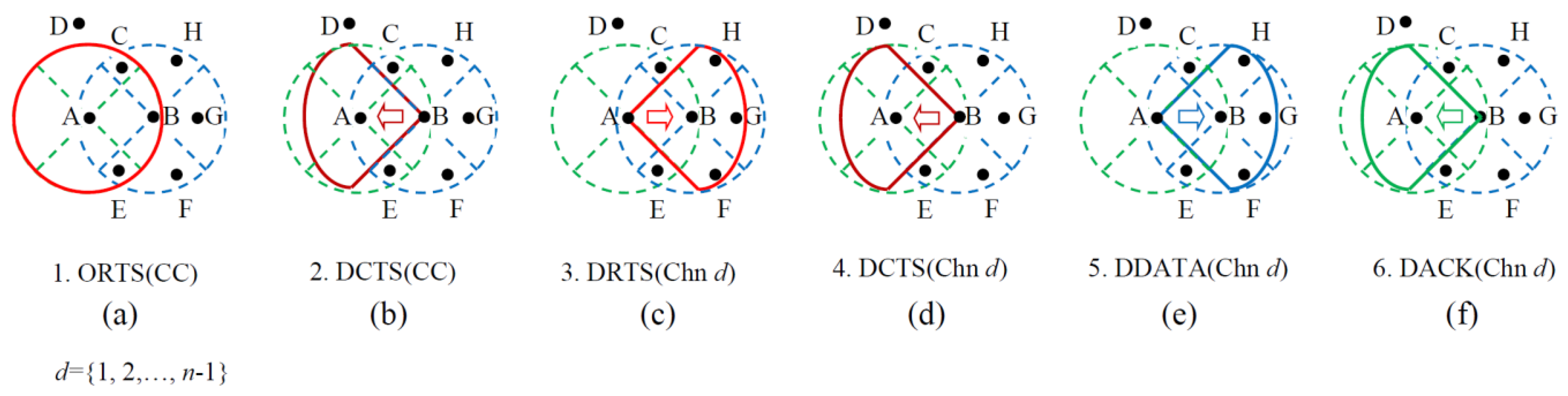
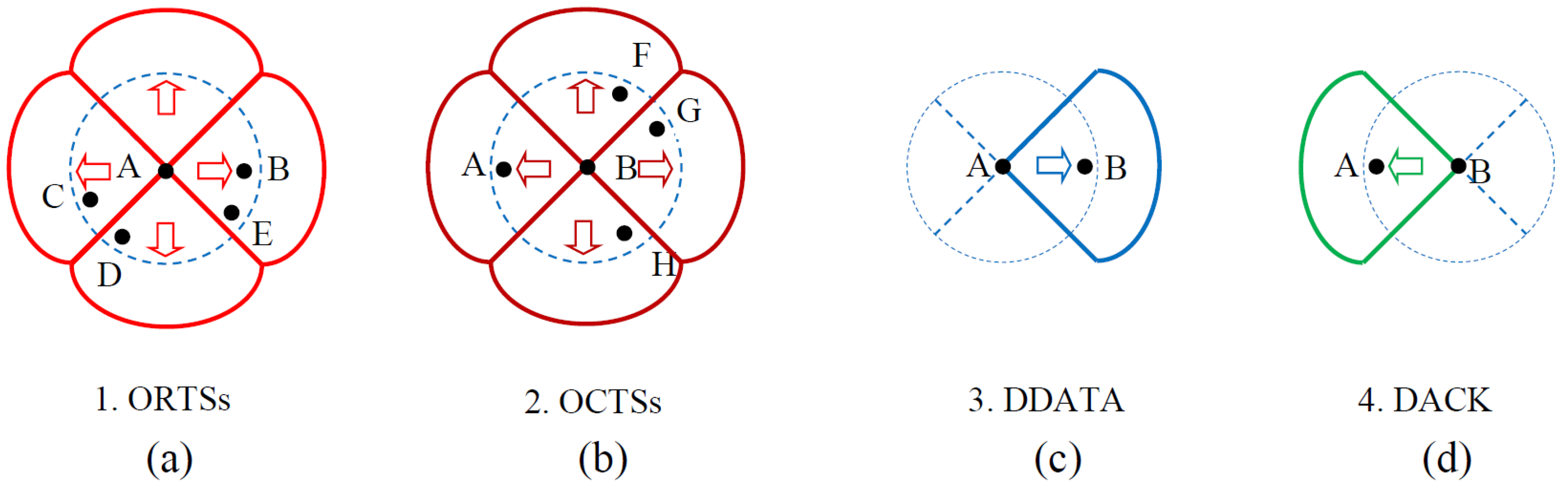
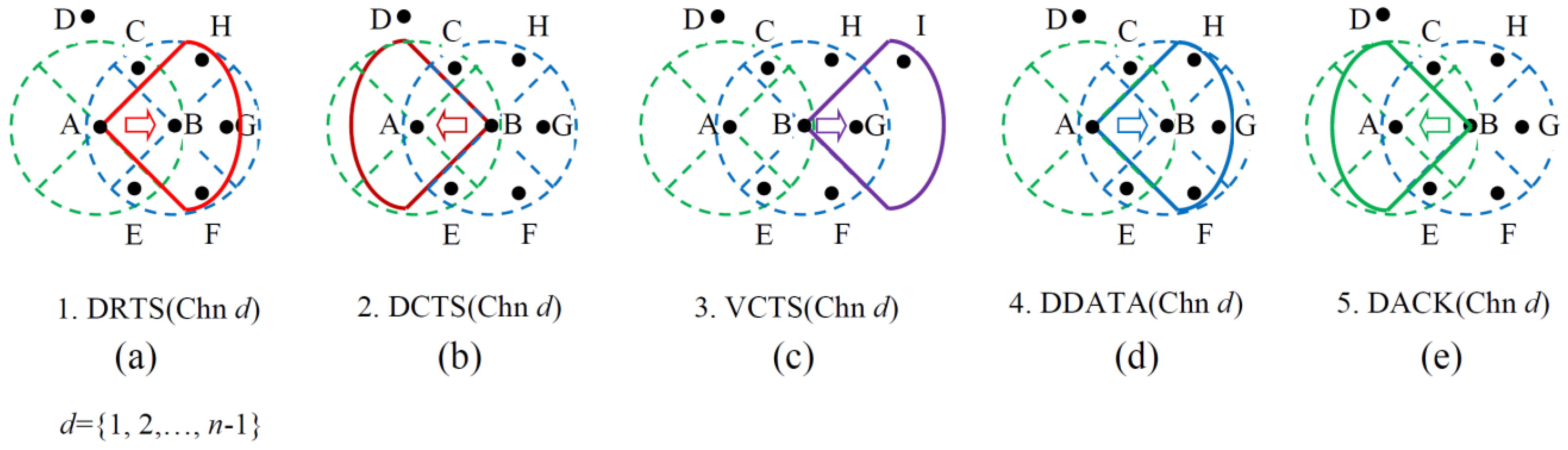
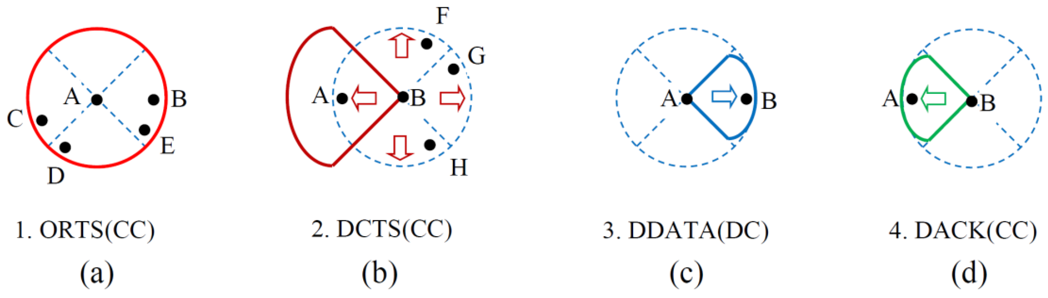
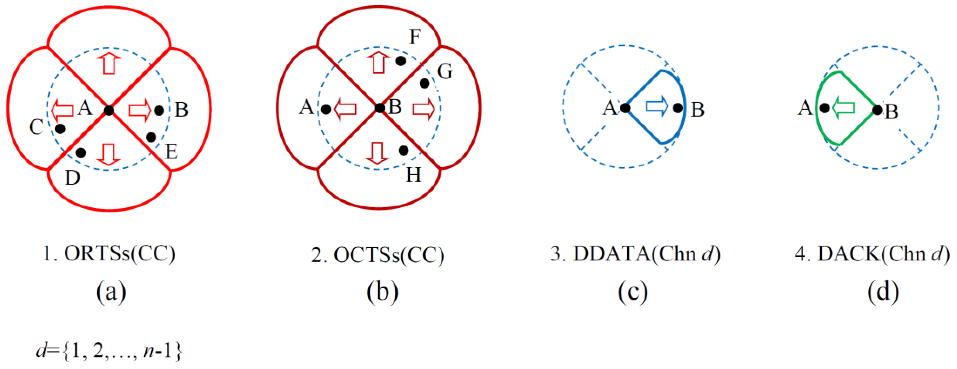
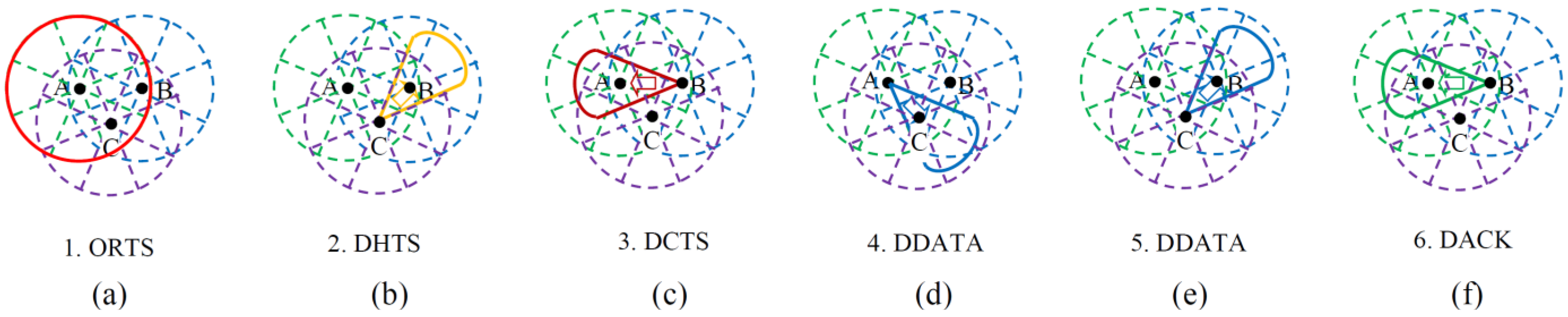
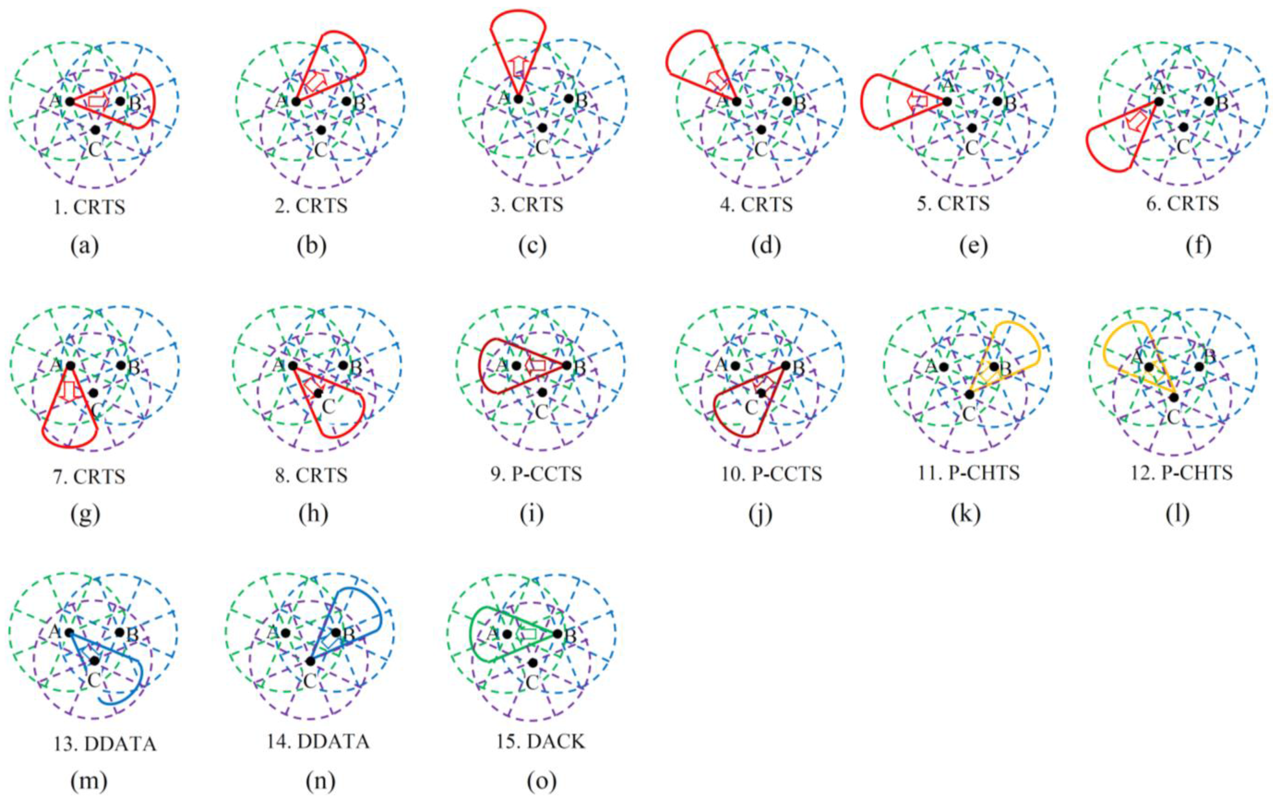
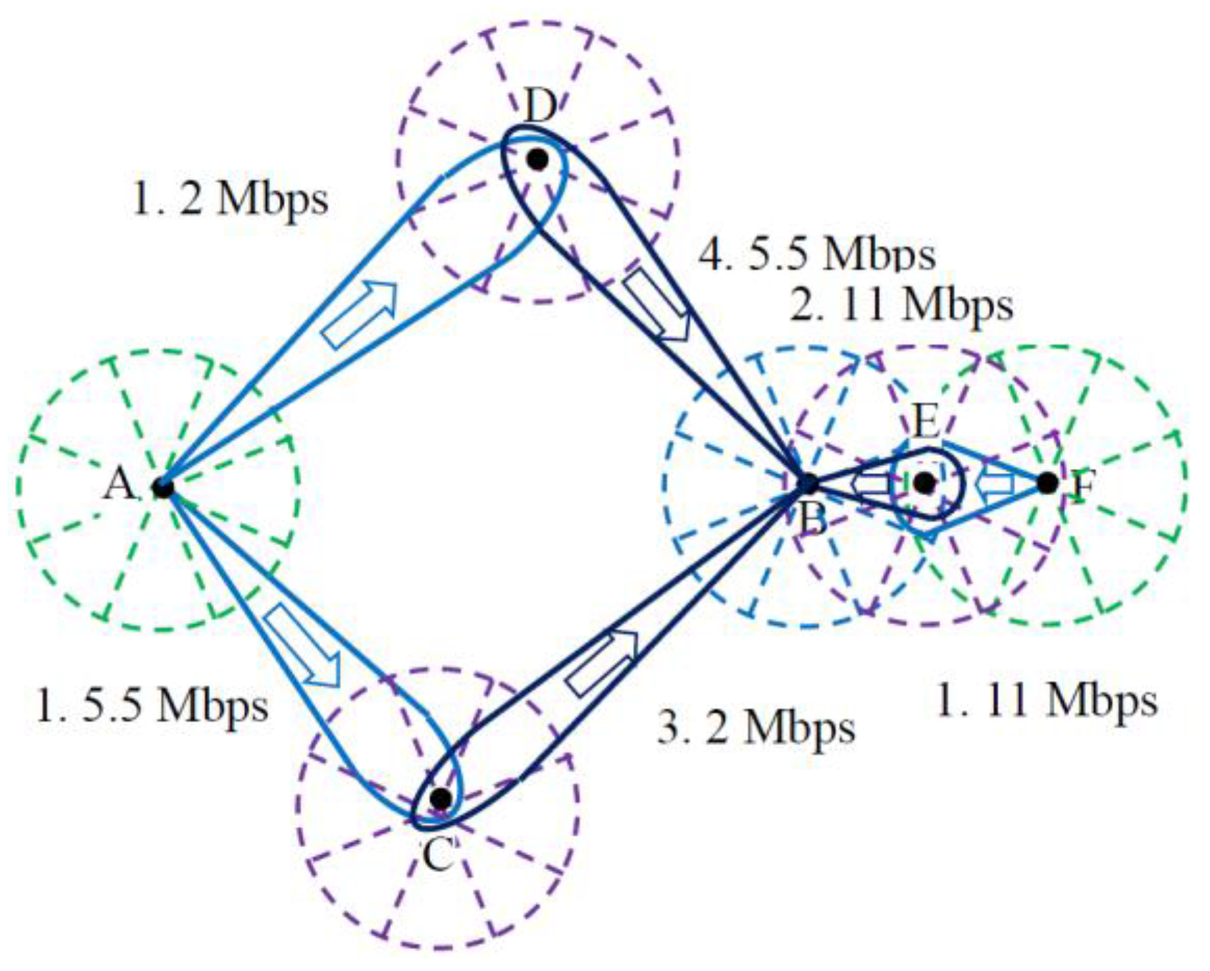
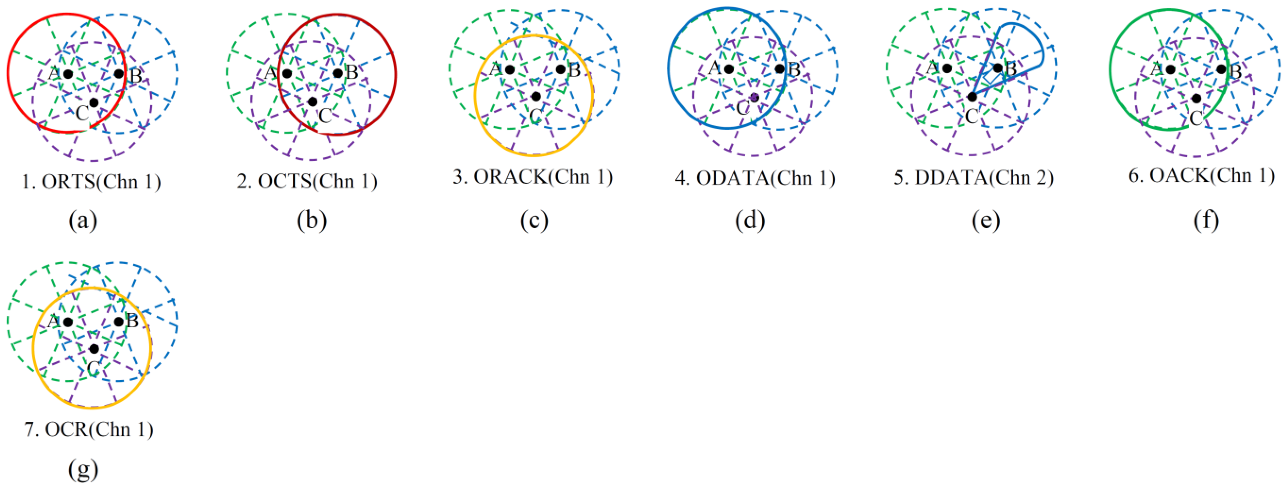
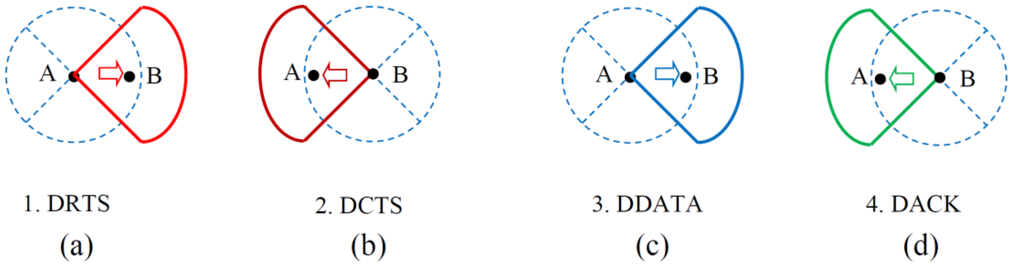
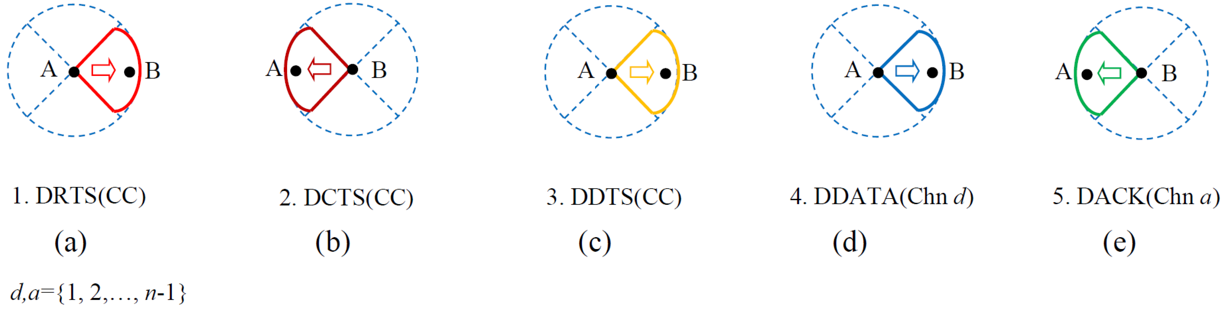
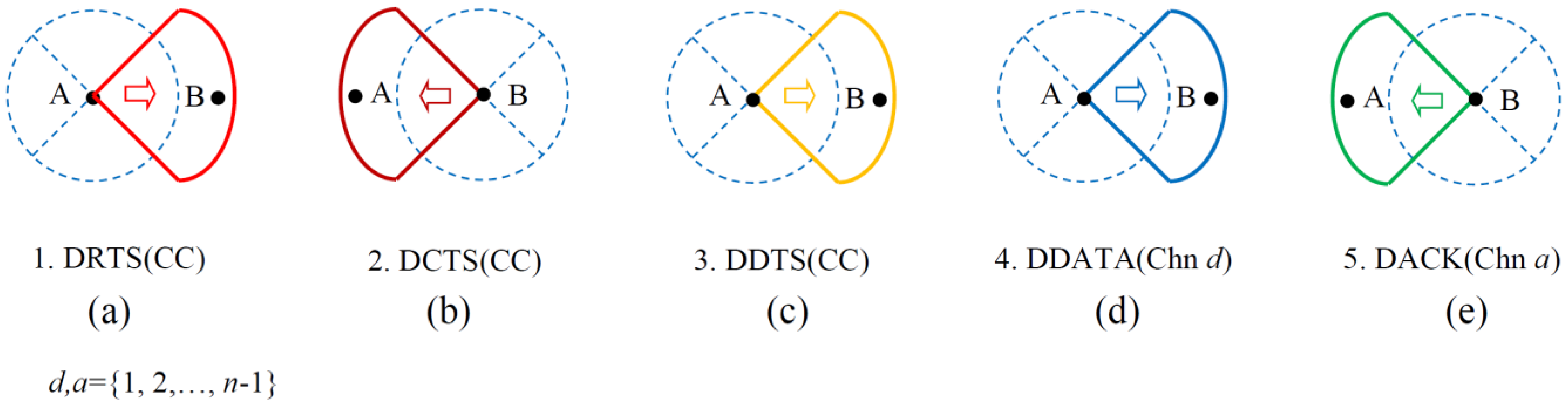
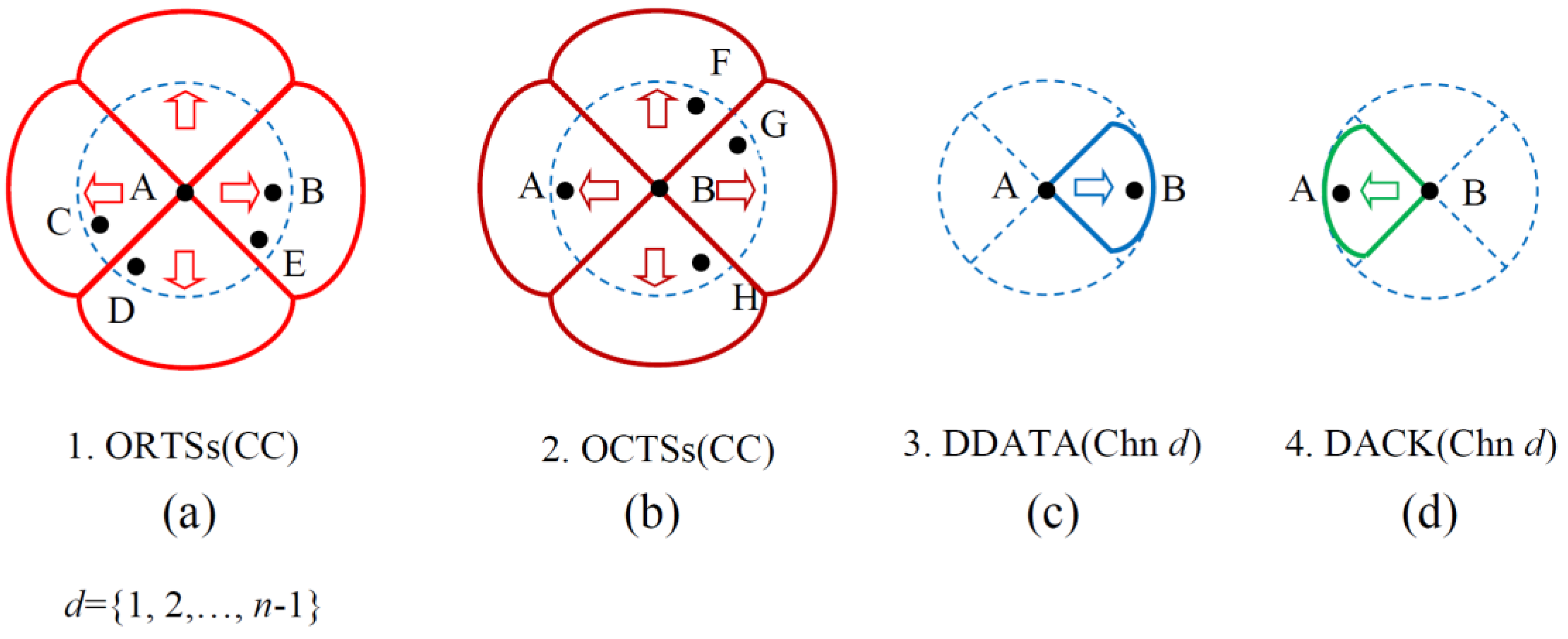
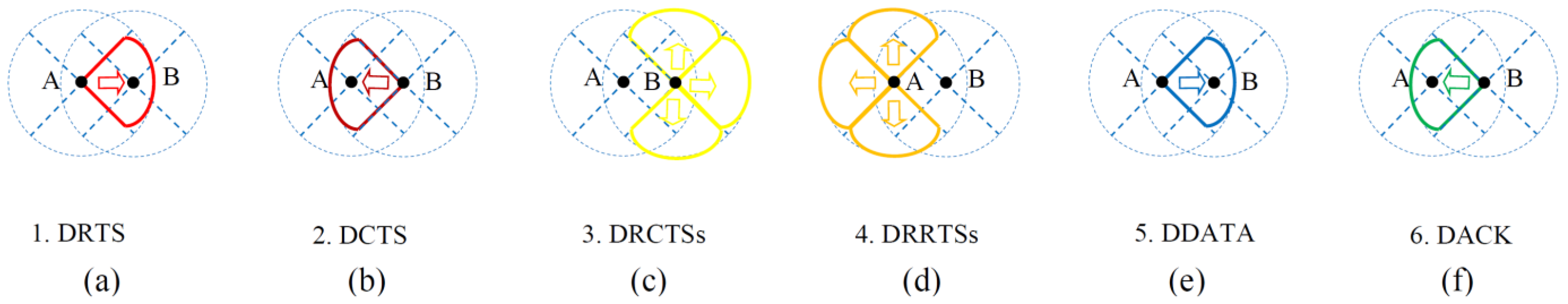
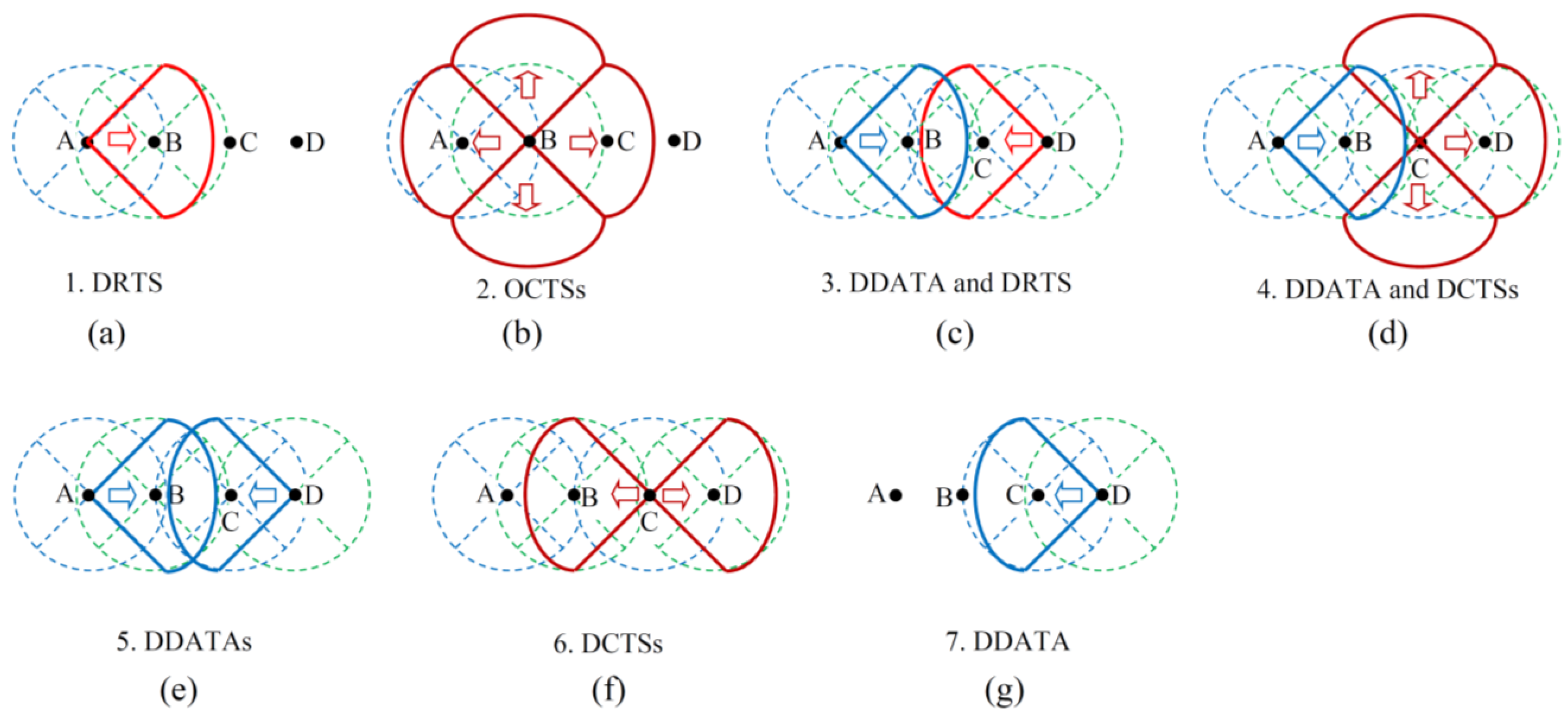
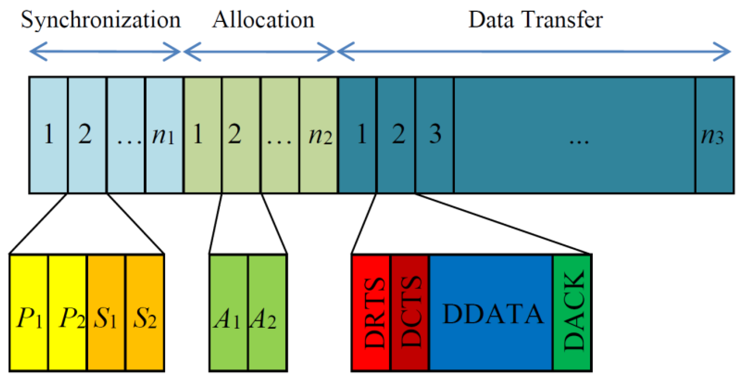


