Article

Cloud-Enhanced Robotic System for Smart City Crowd Control

1
School of Software and Electrical Engineering, Swinburne University of Technology, Hawthorn VIC 3122, Australia
2
Data61, CSIRO, Sandy Bay TAS 7005, Australia
3
Department of Electrical and Electronic Engineering, The University of Melbourne, Parkville VIC 3010, Australia
4
Agency for Science, Technology and Research (A*STAR), Singapore 138632, Singapore
*
Author to whom correspondence should be addressed.
J. Sens. Actuator Netw. 2016, 5(4), 20; https://doi.org/10.3390/jsan5040020
Submission received: 25 May 2016 / Revised: 28 October 2016 / Accepted: 25 November 2016 / Published: 21 December 2016
(This article belongs to the Special Issue Wireless Sensor Networks for Smart Grid and Smart City Applications)

Abstract

:
Cloud robotics in smart cities is an emerging paradigm that enables autonomous robotic agents to communicate and collaborate with a cloud computing infrastructure. It complements the Internet of Things (IoT) by creating an expanded network where robots offload data-intensive computation to the ubiquitous cloud to ensure quality of service (QoS). However, offloading for robots is significantly complex due to their unique characteristics of mobility, skill-learning, data collection, and decision-making capabilities. In this paper, a generic cloud robotics framework is proposed to realize smart city vision while taking into consideration its various complexities. Specifically, we present an integrated framework for a crowd control system where cloud-enhanced robots are deployed to perform necessary tasks. The task offloading is formulated as a constrained optimization problem capable of handling any task flow that can be characterized by a Direct Acyclic Graph (DAG). We consider two scenarios of minimizing energy and time, respectively, and develop a genetic algorithm (GA)-based approach to identify the optimal task offloading decisions. The performance comparison with two benchmarks shows that our GA scheme achieves desired energy and time performance. We also show the adaptability of our algorithm by varying the values for bandwidth and movement. The results suggest their impact on offloading. Finally, we present a multi-task flow optimal path sequence problem that highlights how the robot can plan its task completion via movements that expend the minimum energy. This integrates path planning with offloading for robotics. To the best of our knowledge, this is the first attempt to evaluate cloud-based task offloading for a smart city crowd control system.

1. Introduction

In recent years, cloud robotics has become a prominent area that has merged the two ever-progressing concept of robotics and cloud computing. At present, the robotic service includes sensing, actuating, and control services. Many tedious and potentially dangerous tasks are now possible avenues for deployment of robots because of their high endurance, speed, and precision. Tasks such as 3D path planning for search and rescue [1], navigation tasks [2], and 3D printing, along with scene recognition, scene analysis [3], and medical surgery [4] are examples of services being provided by the highly functional modern robot. Despite all the advancements of late, it is still infeasible to prepare individual robots with limitless capabilities. Every robotic system is bounded by some limitations, whether hardware or software. As the hardware improvements for robotics are constrained to an extent by Moore’s law, there are limited upgrades we can make in that regard. On the contrary, there is still much scope for development as far as software advances are concerned. This is where “cloud robotics” makes its mark.
First coined by Google in 2010, the term “cloud robotics” improves on the shortcomings of networked robotics by leveraging the benefits of cloud computing. Firstly, NIST [5] describes cloud computing as a model for enabling ubiquitous and on-demand network access to a shared pool of configurable computing resources (e.g., networks, servers, storage, and services) that can be rapidly provisioned and released with minimal service provider interaction or management effort. On the other hand, networked robotics has different constraints such as resource, skill-learning and communication. Using the cloud allows the robot to enhance its ability and improve the overall system performance. In fact, according to Hu et al., networked robotics can overcome their limitations by taking advantage of the cloud computing technologies [6].
One of the most promising avenues for implementation of cloud robotics is in a smart city paradigm. Jin et al. defines this as a city that utilizes information and communication technologies to make services and monitoring more aware, interactive, and efficient [7]. A smart city interconnects the physical, Information and Communication Technologies (ICT), social, and the business infrastructure to leverage the collective intelligence of the city [8,9]. With the aid of IoT and cloud advancements, the city infrastructure can provide numerous services to its citizens. This has led to recent studies motivated by lots of opportunities for novel applications.
For cloud robotics systems, cloud resources can be leveraged by offloading complicated and heavy computation tasks for on-demand services. This results in a maximization of the performance level and minimization of task completion time for any system. However, offloading a task to the cloud is not as trivial as is perceived. In fact, it is very complex as it requires a proper trade-off between system computation cost and communication cost. Hence, it is imperative for any process to find the appropriate tasks to offload. One of objectives of this work is to present a cloud robotics framework that enables optimal task offloading. We deploy cloud-enhanced robots to different smart city applications together with the support of IoT network. We chose this platform because of it has ability to deal with complex structures with high performance gurantee in a constrained environment. Our contributions in this paper are listed below.
(a)
We propose a cloud robotics framework that enables task offloading for smart city applications that require a quality of service (QoS) guarantee.
(b)
We provide the scenario of a crowd control robotic system that has a typical task flow, namely DAG used for simulation.
(c)
A genetic algorithm (GA)-based task offloading approach is developed to solve an optimization problem for the given application task flow. We provide results for two different scenarios that show that GA outperforms the other benchmarks in terms of efficiency (i.e., adaptability, overhead time, and energy).
The rest of the paper is presented as follows. Section 2 explains our motivation of cloud robotics for smart city. We also introduce our cloud robotics framework and give a detail description of its different components. This leads us to Section 3, where we provide the example of a robotic crowd control system. In Section 4, a GA based offloading approach is proposed for the formulated problem motivated from the application scenario. This is followed by a performance analysis of the proposed algorithm for two different scenarios in Section 5. In addition to that, we show the adaptability of our algorithm by showing the impact of changing bandwidth and movement on offloading decisions. Section 6 deals with a multi-task flow optimal task sequence problem where the robot finds out the optimal task order to perform movement for successful multi task flow completion. Finally, we produce some information for current trends in Section 7 and conclude our paper in Section 8.

2. A Smart City Cloud Robotics Framework

2.1. Motivating Scenario

As mentioned, the smart city serves as our motivation for cloud robotics application. The current paradigm utilizes ICT to address quality of life as well as provide services to citizens by forward thinking and monitoring environmental parameters. This vision is enabled by the recent influx of IoT with the proliferation of “smart devices”. The peripheral elements of the complex ICT world are the context and geo-aware sensor networks [10]. Through current efforts of the IoT, a pool of heterogeneous sensors is deployed throughout the city that detects critical events and monitors physical magnitudes in order to develop a common operating picture (COP) [11].
As the smart city is a multi-dimensional concept, it can evolve and adapt with upcoming technologies. The functionality of the IoT network is enhanced by the addition of cloud computing. The cloud provides a virtual infrastructure for utility computing which integrates monitoring devices, storage devices, analytics tools, and visualization platforms. Through the interconnection with sensing, all the information is shared across platforms for innovative applications.
With the unified framework of sensing and cloud computing resources, the biggest drawback lies in its lack of mobility and actuation. That is why the next logical step for improvement in this context is the introduction of robots. The robotic network is a complementary addition to the current static IoT devices that has the potential to be a central ICT component of the smart city. It adds an actuating dimension to complement the wireless network of sensors by interacting with the environment. As robotic agents are able to perform mobile and interactive services, they can be deployed throughout the city (Figure 1) for different purposes. By leveraging the cloud facilities, autonomous robots would enhance its computational resources in order to perform more difficult yet beneficial service actions. A number of specific application domains have been identified that can utilize the unified infrastructure for service operations in health services (robotic surgeries), tourism (guide robots), security services (patrol robots, crowd control robots), transport services (smart traffic police), and emergency management (fire-fighting robots). Our case study of smart city crowd control system is a perfect example of cloud robotics where the framework utilizes the available resources of wireless sensor networks (WSN) and cloud infrastructure to patrol different areas and control crowds. A detailed explanation of the system is provided later in the paper.

2.2. An Overview of the Framework

In this section we present a brief overview of our cloud robotics framework. The different available cloud computing models that incorporate machine to cloud (M2C) interaction/communication are mentioned by Hu et al. [6]. As each model has its own pros and cons, we consider various factors such as QoS, adaptability, interoperability, and scalability to choose our design. We propose a three layer (cloud, robot, and sensors) novel framework which is motivated from our previous study [12] where a mobile access point was used as middleware for connection between IoT sensors and cloud. We have now updated the middle layer with a robotic network to propose the following components:

2.2.1. The Cloud Network

Foster et al. state that the emergence of cloud computing in recent times has provided redundant, inexpensive, and scalable resources on demand to meet challenging and dynamic system requirements [13]. The availability of cloud computing means it can be accessed through the internet from virtually anywhere. Moreover, the cloud aspect of the framework syncs in well with the smart city robotics system. The cloud infrastructure forms the upper layer of this framework. It is comprised of multiple virtual machines (VM) and performs task mapping, computation support, data storage, and analytics etc. Each application supports a different service. The cloud providers are in charge of providing the appropriate service to the end user. Different types of service providers in this context include: Mendix, Google App Engine, Amazon Web Services (AWS), etc.
Platform-as-a-Service (PaaS), Software-as-a-Service (SaaS), Infrastructure-as-a-Service (IaaS), and, more recently, Robot-as-a-Service (RaaS) are all examples of services provided by the cloud computing paradigm. For our framework, we choose the PaaS as it provides a software development kit (SDK) that supports different languages. It enables further development of codes as well as a platform to build in new codes. The cloud centre can also access various OpenCV libraries to run different programs and provide on-demand computation/service to the user.

2.2.2. The Robotic Network

The central component of this framework is the robotic network. It is the lynchpin that connects the bottom and upper layer. The primary criteria of the network robotic system in our paper are the ability of the robots to collect data from the sensors, interact with the environment, and perform movement when necessary to accomplish tasks. The robot also accesses the cloud to offload some heavy computation tasks to the cloud to improve the system performance. The features of the robots are four-fold: communication, task offloading, actuating, and mobility. The robotic network has the objective of completing the task set for a given scenario. The ability to communicate allows the robot to connect and collect data from the bottom layer sensors (Figure 1). Being Wi-Fi enabled, the robot connects to the cloud infrastructure on-demand. With sufficient processing power, the robots can also offload tasks to leverage the ubiquitous computation facilities of the cloud.
Given the scope of our application, many tasks may require movement to different locations. The distinctive attribute of the robots in a smart city environment is its mobility feature which ensures that the robots can move on demand to different locations and connect to different sensor devices to perform action-based tasks. This also gives robots options to find better bandwidth for offloading. The navigation can be done using the on-board components of the robot as well as using the cloud service when necessary. Other action-based tasks may be data-intensive and may require further assistance from the cloud. The correct offloading decisions must be made by the robot to meet the system QoS requirement. This is what makes robot the core unit of this framework.

2.2.3. The Wireless Sensor Network

WSNs are the bottom layer of the framework that enables the collection, processing, analysis, and dissemination of valuable information gathered in the environment. The WSN comprises of different types of low-cost and limited-energy sensor devices (e.g., smart meters, data storage devices, photographic tools, camera networks, etc.) with the raw data necessary for application specific tasks.
In a smart city scenario, different wireless sensors can be deployed throughout the city for environment monitoring purposes. Many of these devices may not have Internet connectivity. So, direct communication with the cloud is not possible. Instead, a wireless connection with the middleware can occur when the robot is within the range. In this way, the WSN complements the functions of the robotic network by supplying monitoring data. The sensor devices can also interconnect with each other and provide processed information (location, person of interest, object view, etc.) through local communication that would direct/assist the robot to complete the tasks.

3. Smart City Crowd Control

One of our major contributions in this paper is the presentation of a smart city crowd control system via cloud-enhanced robots. In our scenario, a robotic agent is in patrol mode and in charge of monitoring and controlling a crowd for a given location (e.g., a station, park, building, or stadium). This system uses surveillance footage captured by IoT networks of camera sensors to collect and process data. Based on that, many action-based tasks are completed by the robot agents. The presence of cloud infrastructure enables an offloading approach to improve the system performance and assure QoS in terms of completing the given sets of task under certain constraints. The main purpose of this section is to provide evidence to justify operations of cloud-enhanced robots for crowd control.

3.1. System Operation

The complete operation of a crowd control system can be divided into three integral stages. All of them might happen during the course of any given event. The performance of the system will depend on the operation all these tasks. A typical 20-node task flow represents the different aspects of the operation.
Identification Event
This initial stage of the application is a merger of surveillance by camera sensor networks and the robotic agent. The camera WSN collects surveillance data. Upon that, heavy analysis is done by the camera to detect and identify any person of interest who may be a threat or require assistance. This triggers the first-on-scene incident. The location data of the person is wirelessly forwarded to the robotic agent that is positioned within the range of the WSN. Based on that, the robotic agent then devises a path plan to move to that location. As seen in Figure 2, path planning involves heavy computation tasks such as path analysis and collision detection.
Investigation Event
The next step of the incident involves robot performing some investigative tasks. Upon arrival, the robot identifies the correct person to interact with via a face match with the agent-mounted camera. Then the situation is assessed by capturing and analysing the gesture recognition, now in more detail. The agent also begins verbal communications with the person to detect speech patterns. With these analyses complete, the system can determine the best course of action: continue questioning, contact the appropriate authorities, or guide to a nearby safe location. The investigation event does not require much movement; however, it consists of several complex tasks that require timely execution in order to make proper decisions for the next stage of operation.
Guide Event
Another major aspect of the robotic crowd control system is the service provided by the robotic agents in the guide event. When the robotic agent needs to escort/guide a person of interest to a given location, then this event is triggered. At that point, the robot will perform the path planning operation and use the camera network to move and guide the person. This guiding action will call upon the navigation process so that the robot can successfully move through the obstacles via path planning. The robot also needs to monitor the person to ensure that he or she is following. The guide event is a unique feature of the robot as it involves movement as well as interaction. All of these tasks involve complex computation in order to provide the necessary service.

3.2. System Architecture

For the application, we show the system architecture that follows the framework proposed in the previous section. The three-tier architecture (Figure 1) has the following components:
Firstly, the sensor network is represented by the camera network that is wirelessly connected with robotic agent. As shown in Figure 1, the cameras cover the targeted area to provide invaluable monitoring data. The objective is to collect surveillance feeds which are used to monitor a large group of people simultaneously. In addition, object and gesture recognition processes are performed by the camera on this footage to determine if a security incidence is taking place. Thus, the camera network supplies the robotic agents with processed data that are necessary to provide complete coverage of the area. It also directs the robots to take action for first-on-scene incident control. The term “camera network” and “wireless sensor network” will be used in this application to indicate the same thing.
Secondly, the middle tier consists of the robotic agent. It is the critical component of the system and provides interaction, actuation, and mobility, as well as task offloading. The autonomous robotic agent is in patrol mode, roaming the complete area and at the same time getting important information regarding security. If an incident occurs, the robotic agent is directed to the location of interest, which leads to the robot having to complete several complex tasks to control the situation. In addition to being an incident control system, the agent also provides a security presence, deterring anti-social behaviour by patrolling the crowd throughout an event. The robotic agent’s actions involve completing some tasks such as path planning, noise analysis, image analysis, guiding personnel, etc. Depending on the type of task and availability of resources (cloud based VM, sensor networks), the task complexity of the robotic agent may vary.
Finally, the top-tier cloud infrastructure provides the robotic network with a computational platform to support the robotic agent and improve the QoS for the application. The cloud infrastructure consists of powerful computing processors that will provide faster computation. The AWS platform is used as the service provider that supports PaaS. An Application Programming Interface (API) is implemented using the object-oriented programming languages in the PaaS layer. Being scalable, the available processing power can be varied depending on the complexity of the tasks. When needed, the robotic agent is able to offload tasks that need heavy computation to the cloud. However, not all tasks are possible or desirable to be offloaded. In fact, some tasks (i.e., movement, interaction) must be performed by a robot. A proper strategy (algorithm) is required to optimally allocate tasks to appropriate resources for successful task completion under given constraints.

4. A Task Offloading Approach

We propose a framework for crowd control system (Figure 1) that utilizes a unified network of robotic and cloud infrastructure. Therefore, a proper task allocation between the robot and cloud is intended to make sure that performance enhancement is achieved. In this case, allocating the task to the cloud is referred to as task offloading. So, both are interchangeable for the context of this paper. We use the application task flow in Figure 2 to define the optimization problem. Based on that, we then implement a genetic algorithm based offloading method to solve the problem. Using the GA-based algorithm, we identify the correct tasks to offload to the cloud, which results in system QoS improvement.

4.1. Problem Formulation

We derive a task graph from the motivating application scenario (Figure 2), where a graph is presented as a sequence of dependent tasks to be completed by a robot under constraint. We model our application by using a DAG to indicate our task flow where each task is represented by a node. We present the DAG by using a tuple, D = ( T , K ) . In this case, T = { v j ,   j = 1 : t } and t = | T | . Here T denotes a task node. We also assume, K = { k i , j = v i , v j } and k = | K | . K implies a set of edges that refers to the communication cost from node v i to v j .
The term t i denotes a task i in the task graph where its execution time is dependent on the computation of v i t h task with input data d i . All the task nodes are indicated by Tasks t 1 …… t T . We also assume that the nodes on the same level of the DAG (e.g., Tasks 4 and 5) are independent and limited by the “dependency of precedence”. As a result, a task can start only after all its preceding tasks on the previous level have been completed. The highlighted nodes indicate tasks such as movement (Task 19 in Figure 2) and interaction (Task 9 in Figure 2) that are conferred on the robot. Table 1 provides the necessary notation for the calculation of the cost functions. In implementing our offloading approach, our goal is to find the optimal offloading decisions to complete the task flow within the provided constraints. The following factors are taken into consideration for offloading:
  • The processing capabilities of robot and cloud VMs
  • Movement cost
  • Cost of communication
  • WSN connection.
The cost functions implemented in this problem formulation are briefly presented in our previous work [14].

4.1.1. Cost Functions for Robotic Energy Consumption

E t o t a l = i = 1 | T | I t i .   E R ( t i ) + i = 1 | T | ¬ I t i .   E C ( t i )
E R ( t i ) = E M o v ( t i ) +   E W S N ( t i ) +   E R C ( t i )
E C ( t i ) = E M o v ( t i ) + E W S N ( t i ) + E U ( t i ) + E I ( t i ) + E i d l e ( t i )
In this equation, E t o t a l is the total energy consumption of the robot. I t i denotes the offloading decisions and ¬ stands for the NOT operator. The robotic energy costs of a task taking place on robot and cloud are represented by E R and E C , respectively. We use E I and E U to indicate communication costs for sending task related instructions and uploading collected data to cloud:
E I ( t i )   = P i × B P I × N ( t i ) β
E U ( t i ) = t i   v ( t ) P u × d u ( t i ) β
In Equation (5), v ( t ) is a set that represents tasks where robot collects data from sensors in WSN. P i and P u are the robot processing power for their corresponding communication.
E R C ( t i ) =   P r × C P I × N ( t i ) S r
E i d l e ( t i ) =   P i d l e × C P I × N ( t i ) S c
E W S N ( t i ) =   t i   D ( t ) P d × d d ( t i ) T r
E M o v ( t i ) =   t i   M ( t ) P m o v × ( x a   ~ x b   ) 2 + ( y a   ~ y b   ) 2 R v  
In Equation (6), E R C ( t i ) indicates the energy of robotic computation energy, whereas E i d l e ( t i ) in Equation (7) defines the computation energy for a robot when a task is being executed on the cloud. P r and P i d l e indicate the processing power that the robot consumes during the respective computation process. Also, E W S N ( t i ) is the cost for connection with devices in the WSN. We consider D ( t ) as the set of tasks for which the robot needs to collect data. T r is the data transfer rate between the robot and WSN. The processing power of the robotic agent for data collection is indicated by P d .
For movement, each zone is represented by its individual coordinates. We show three coordinates to imply that different events may take place in separate locations. As the robot moves from one zone to another, we calculate the shortest distance between two coordinates as the distance between the corresponding locations. For example, tasks that need movement from one zone ( x a ,   y a ) to another ( x b ,   y b ) are considered as part of the set m ( t ) . Based on this, we calculate the robot movement energy cost E M o v ( t i ) in Equation (9). As the robot may need movement for data collection as part of some tasks taking place in both robot and cloud, we consider E M o v ( t i ) in Equations (2) and (3). The robot velocity and power consumption during movement are R v and P m o v . We also assume the communication bandwidth β of all zones to be different. So the available bandwidth is a determining factor for offloading.

4.1.2. Cost Functions for Time Calculation

T t o t a l = i = 1 | T | I t i .   T R ( t i ) + i = 1 | T | ¬ I t i .   T C ( t i )
T R ( t i ) = T M o v ( t i ) +   T W S N ( t i ) +   T R C ( t i )
T C ( t i ) = T M o v ( t i ) +   T W S N ( t i )   +   T U ( t i ) +   T C C ( t i ) +   T I ( t i )
The total task execution time is specified by T t o t a l . The term T R indicates the time for tasks that are commencing on the robot and T C means the execution time for tasks in the cloud VM. T U and T I are the communication costs for sending task-related instructions and uploading collected data to the cloud.
T I ( t i )   = B P I × N ( t i ) β
T U ( t i ) = t i   v ( t ) d u ( t i ) β
T W S N ( t i ) =   t i   D ( t ) d d ( t i ) T r
T M O V ( t i ) = t i   M ( t ) ( x a   ~ x b   ) 2 + ( y a   ~ y b   ) 2 R v
T M o v ( t i ) and T W S N ( t i ) are the respective values of the tasks that need movement and WSN connection. The computation time for tasks that are commencing on the robot and the cloud are T R C and T C C .
T R C ( t i ) =   N ( t i )   ×   C P I   S r
T C C ( t i ) =   N ( t i )   ×   C P I   S c
The Clock speed of the VM processor in cloud is considered to be M times faster than the robot ( S c = M   ×   S r ).

4.1.3. Optimization Problem

With regards to the problem formulation and the presented cost functions, the objective is to find optimal offloading decisions for this application. We consider two scenarios for simulation. In each case, the binary variable I t i = {0, 1} indicates the offloading decision options for a given task.
  • I t i ( 1 ) specifies that the task t i is executed on the robot.
  • ¬ I t i (0) specifies that the task t i is executed on the cloud.
Scenario 1 (Minimise Energy)
In this proposed scenario, we have to obtain the optimal offloading decisions ( I t i ) where the objective is to minimise the robotic energy consumption (Minimise: E t o t a l ) and the constraint is task completion time/delay deadline ( T d e a d l i n e ). That means,
Find :   { I t i }  for  T = { v j ,   j = 1 : t }  and  t = | T |  to
Minimise :   E t o t a l
s . t . :   T t o t a l   T d e a d l i n e .
Scenario 2 (Minimise Time)
The objective is vice versa. We have to find the optimal offloading decisions ( I t i ) to minimise the task completion time/delay (Minimise: T total ) under the defined energy constraint. That means,
Find :   {   I t i   }  for  T = { v j ,   j = 1 : t }   t = | T |  to
Minimise :   T t o t a l
s . t . :   E t o t a l   E l i m i t .
Based on that, we implement a GA-based offloading scheme to solve the optimization problem.

4.2. A Genetic Algorithm Based Task Offloading Method

Genetic algorithm (GA) is an adaptive heuristic search algorithm based on the evolutionary ideas of natural selection and genetics. It represents an intelligent exploitation of random searches used in order to solve optimization problems. In GA, weak and unfit species are faced with extinction by the process of natural selection, whereas the strong ones have a higher possibility of passing their genes to future generations via reproduction [15]. GA is used to obtain optimized solutions from a number of candidate solutions [16]. Although randomized, GAs are by no means random; instead they exploit historical information to direct the search into the region of better performance within the search space. We use a genetic algorithm because it is a widely recognized global optimization algorithm that is used in many fields because of its high efficiency and impressive stability [17,18].
In this paper, we propose a GA-based task offloading scheme. The purpose of using GA is to find out the optimal task offloading decisions (as mentioned in scenario 1 and 2) with respect to the given problem. To implement the genetic algorithm based scheme, we need to follow the six regulatory steps (as shown in the Figure 3).

4.2.1. Chromosome Encoding

As seen in Figure 3, the first step of implementing GA is to encode the chromosomes (possible solutions) with respect to the problem set. In GA, a chromosome generally represents a unique solution (task offloading decision) for a problem. In our case study, we consider that an integer vector I = [ I t 1 , I t 2 ,... I t i ,… I t T ] corresponds to a solution where T is total number of task nodes and each I t i contains the value either 0 (on cloud) or 1 (on robot). For example, a chromosome I = [1, 0, 0, 1] indicates a solution where Tasks 1 and 4 are allocated to take place on a robot, whereas Tasks 2 and 3 would take place on the cloud. Once a random chromosome is encoded, we further constrain certain tasks (e.g., movement, interaction, etc.) of the chromosome by forcefully allocating them on the robot. This is done to accommodate the tasks that can only be done by a robot because of its nature (highlighted in the task graph in Figure 2).

4.2.2. Fitness Evaluation

The fitness function is a parameter that defines the quality of the proposed solutions in the search space of a generated population. Once the chromosomes/individuals in the population have been generated, they are evaluated and fitness scores are acquired for each solution (Figure 3). For the given problem, we have two scenarios and therefore two fitness score.
  • Scenario 1 (Minimise: Energy), we consider the fitness, f = E t o t a l .
  • Scenario 2 (Minimise: Time), we consider the fitness, f = T t o t a l .
In both cases, the objective is to find the solution/chromosome that provides the lowest fitness score. The lower fitness results in a better (more optimal) solution. In each generation, the total robotic energy consumption, the task completion delay, and all the other associated values are calculated for a given population using the above mentioned equations.
The pseudo-code for calculating total robotic energy consumption ( E t o t a l ) and the delay ( T t o t a l ) are presented in Figure 4 and Figure 5, respectively. In both cases, the calculation for task graph is done level-wise. This means a task flow is searched to find all the node dependencies between each of the levels. These are used to divide the task nodes in a number of groups. Tasks on each level are considered as a “task group”. Using all that information, we calculate the values of E t o t a l and T t o t a l for both scenarios.
Calculation of E t o t a l
For every task level, the robot checks each task for its allocation (robot or cloud). Based on that, values of E R ( t i ) , E C ( t i ) and E t o t a l are updated. Then it moves on to the next level to complete the same task and add to the value of E t o t a l . This is done until tasks on each level have been considered and calculated. At that point, it collects the result of E t o t a l , which is the final value of total robotic energy consumption for that proposed solution.
Calculation of T t o t a l
In case of calculation for T t o t a l , the process is similar but slightly more complex. As tasks on the same level can happen in parallel, the total time for all tasks is not additive. Therefore, the process is slightly modified. Time calculation is done for each task level and the allocation is checked for each task. As seen in Figure 5, for parallel tasks (also known as task groups) on the same level, time/delay for the tasks taking place on cloud and robot are calculated and updated on T R ( t i ) and T C ( t i ) , respectively. Then a comparison is done between the two to find which consumes more time. For each task level, a comparison is made to collect the higher value between T R ( t i ) and T C ( t i ) . That value is considered as the time needed to complete tasks on that particular level. It is then added to T t o t a l . This is done for all the levels, by which we obtain the final value of total time ( T t o t a l ).
During the fitness evaluation phase, both scenarios have their own objectives and constraints. For the first scenario (Minimise: E t o t a l ) the constraint is task completion time/delay ( T t o t a l   T d e a d l i n e ). For the second scenario (Minimise: T t o t a l ), the constraint is robotic energy consumption ( E t o t a l   E l i m i t ). Based on that, the fitness score is evaluated for every solution that meets the corresponding constraint. Every time there is a fitness score lower than the previous one, the lowest fitness score is updated. This way, the solutions are being improved until they reach the minimal fitness score.

4.2.3. Selection Phase

The selection phase is followed by the fitness evaluation (Figure 3). In this phase, a mating pool is generated. The purpose is to gather the solutions considered to be “good”. Thus, the chromosomes with fitness lower than the average fitness score are collected. At the end of this stage, two chromosomes with good fitness scores are randomly selected from the mating pool for breeding at a later stage.

4.2.4. Crossover Phase

The crossover operation is performed once on each selected chromosome pair. The two selected chromosomes from the previous phase “reproduce” in the crossover section and produce “offspring”. Here we consider the uniform crossover, which uses a fixed mixing ratio between two parents. It enables the parent chromosomes to contribute at the gene level rather than the segment level. In this stage, individual bits in the string are compared between two parents. The bits are swapped with a fixed probability.

4.2.5. Mutation Phase

The mutation phase takes place once the selection and crossover are finished. There is now a new population full of possible solutions (task offloading decisions). In some cases, the chromosomes may become too similar to each other. In order to have proper diversity and a higher chance of finding a global optimum, a portion of the new individuals will have some of their bits flipped with certain probability (0.5 in our case) in mutation phase. At the end of this stage, we obtain a new population of individuals.

4.2.6. Stopping Criteria

The final phase of the GA operation is to define the stopping criteria. Once the new population (after the mutation phase) replaces the current population, we move on to the next generation to continue the same process. We input a stopping criterion in GA to find out when the optimal result has been reached. In our case, since GA will provide its “lowest fitness score” after each generation, thus we stop when the lowest fitness score does not change after a prefixed number of generations. At that point, the GA-based scheme stops running and the results (offloading decisions) are considered optimum.

5. Results and Analysis

In this section, we calculate and analyse the results of our given problem. The 20-node graph presented in Figure 2 is used as our task flow for two simulations. In the first one, the objective is to find the offloading decisions that minimise E t o t a l under the time constraint. Then, we show the adaptability of the algorithm by showing the second simulation for a case where the objective is to complete the tasks in minimum time (Minimise: T t o t a l ). For this scenario, the constraint is robotics energy consumption.
We compare the offloading results of the genetic algorithm (GA) with two benchmarks. One is the Exhaustive Search (ES). In ES, all the possible solutions are systematically enumerated to find the optimal one. The purpose here is to verify the accuracy of the GA algorithm. We additionally compare the results with an “all on robot” (AoR) approach where all tasks are considered to be completed by a robot. This result is used to evaluate if the alternative approach with the usage of the cloud infrastructure is beneficial or not. The results help justify the performance and shortcomings of each of the methods.

5.1. Simulation Setup

For the simulation setup, the CPU (Intel Core i5-4570) of the robot is equipped with processing clock speed of 3.2 GHz, CPI value of 20, and BPI value of 8. The VM clock speed at cloud is 1000 times faster than robot CPU. The robotic power rating of the CPU is 84 W. Processing power: P r = P i d l e = 50 W, P i = 35.5 W, P u = P m = 80 W, and P d = 35 W.
From Figure 2, Tasks 1, 2, and 14 require a robot to collect the data from a nearby available sensor network. Tasks 5, 9, 15, 19, and 20 are constrained to be completed by robot and hence the GA based scheme is modified accordingly. In particular, movement-based tasks result in a change of location/zone and available bandwidth for the robot. The task flow in Figure 2 represents two movement-based tasks (5 and 9). That is why three zones have been considered for the simulations. Table 2 presents all the necessary setup details of parameters. For both cases, the simulation is run with a defined stopping criterion (Table 2). The optimal results from simulations are collected along with graphs to analyse and compare the performance of the scheme with respect to other methods.

5.2. Simulation Results

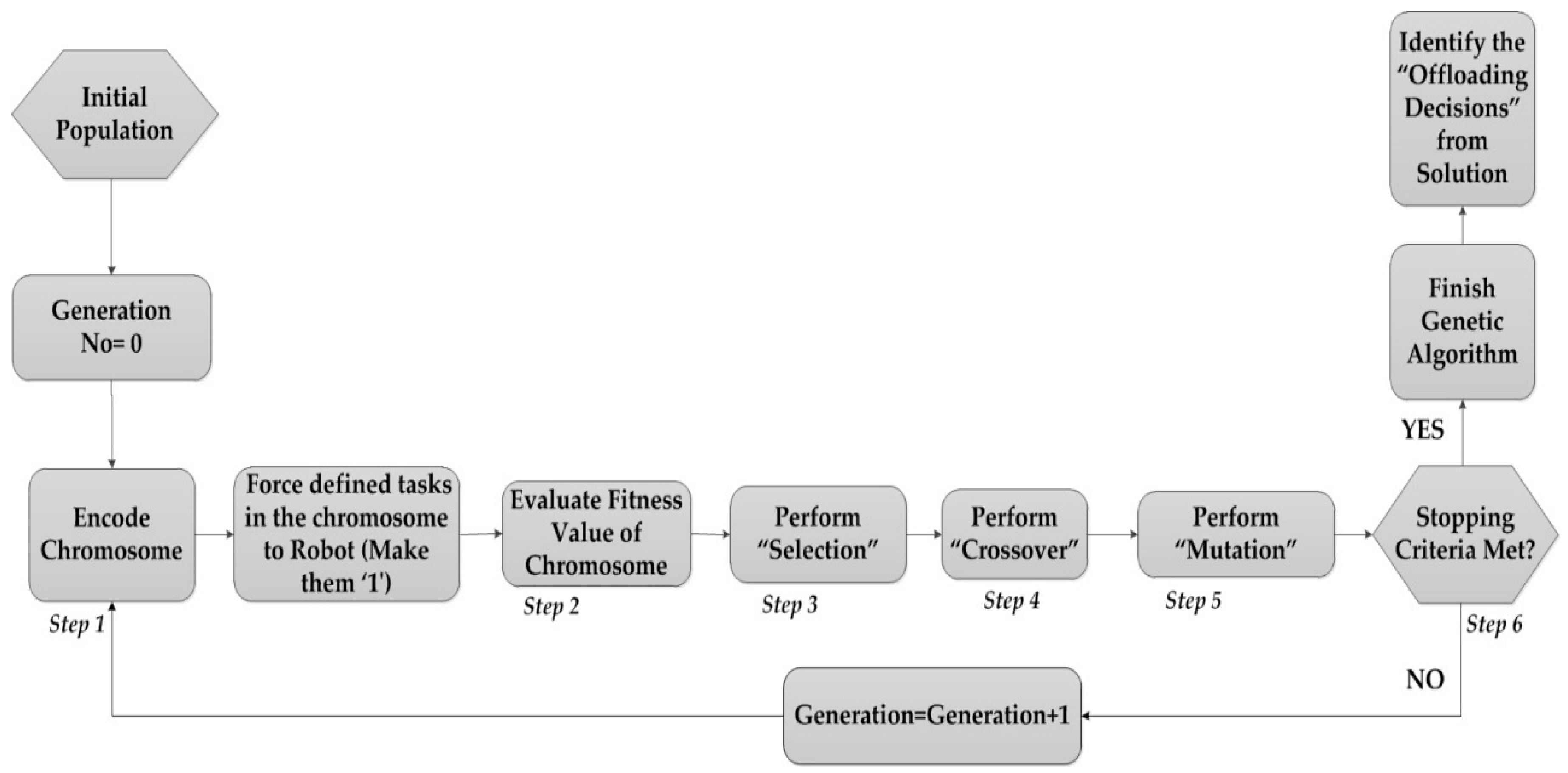
We ran a simulation of a GA-based scheme for 20-node task flow to find the optimal offloading decisions. To show the adaptability of GA in this context, we considered two scenarios. In case there is any shortage of one of the parameters (energy/time), the robotic agent can prioritize the other and adjust the task objectives accordingly.
Scenario 1 (Minimise: E t o t a l )
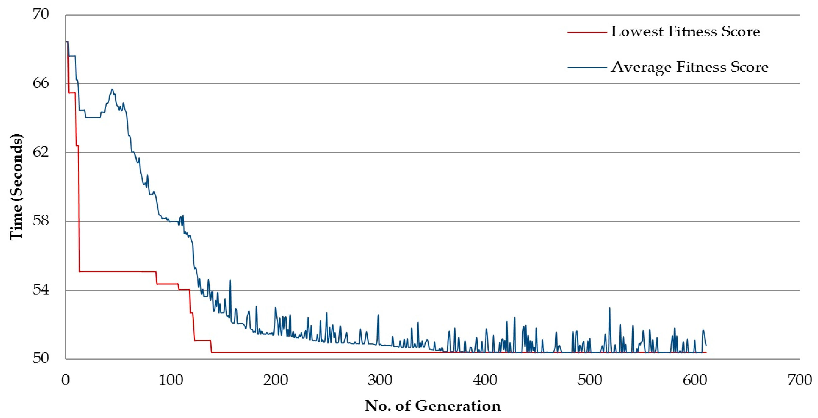
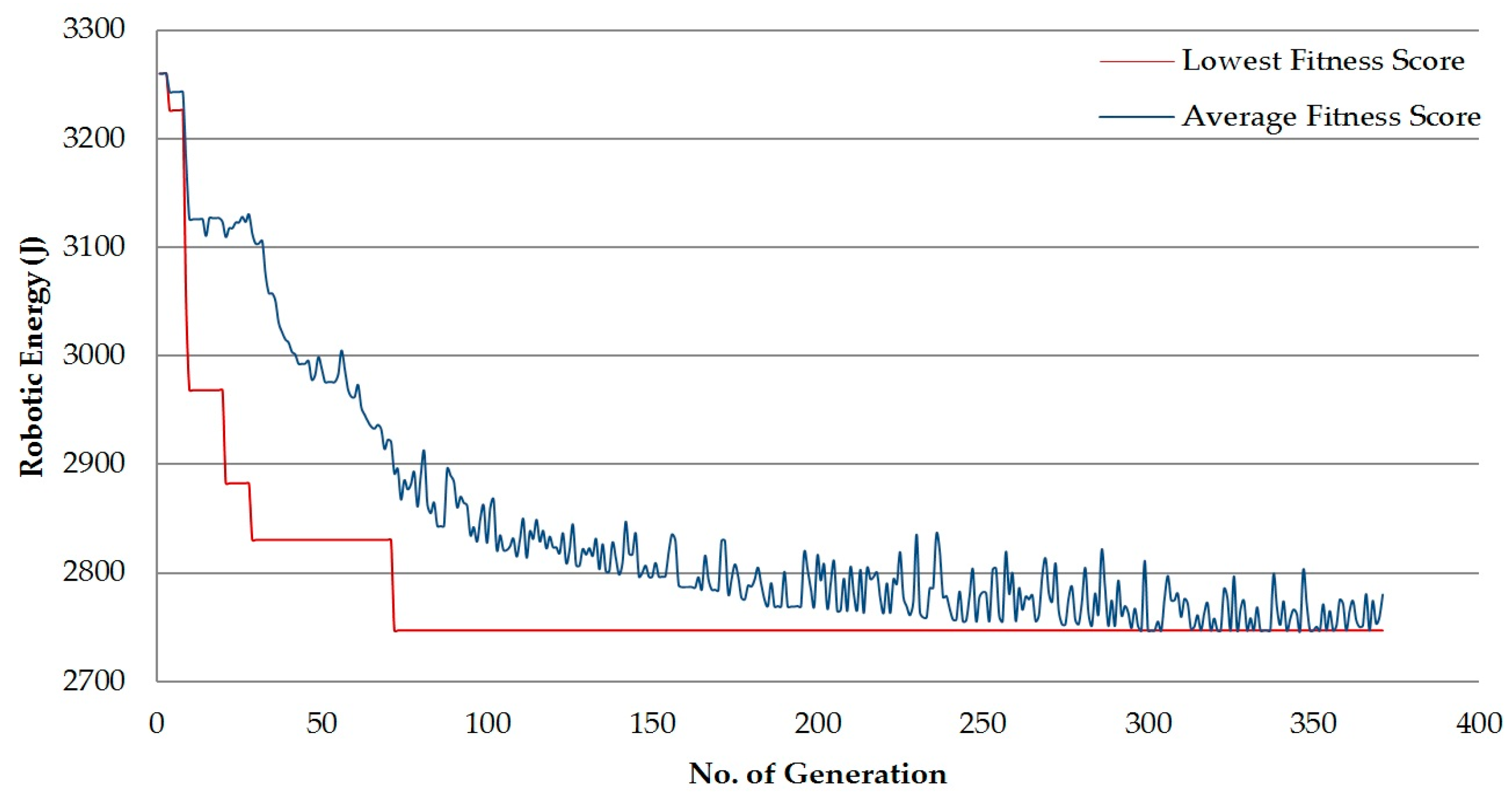
From the simulations with fitness score E t o t a l , the results show that the average fitness score decreases with the generation number (Figure 6). This leads to the conclusion that most generations of GA scheme tend to result in lower fitness and thereby decrease the average fitness score. The lower trend of the graph clearly indicates a process where GA keeps replacing the fitness with lower scores until it finds the minimal one. From Generation 71 onwards, no change in generation score is seen. Hence, GA stops running after 371 generations in accordance with thestopping criteria (Table 2).
The results of the simulation are presented in 
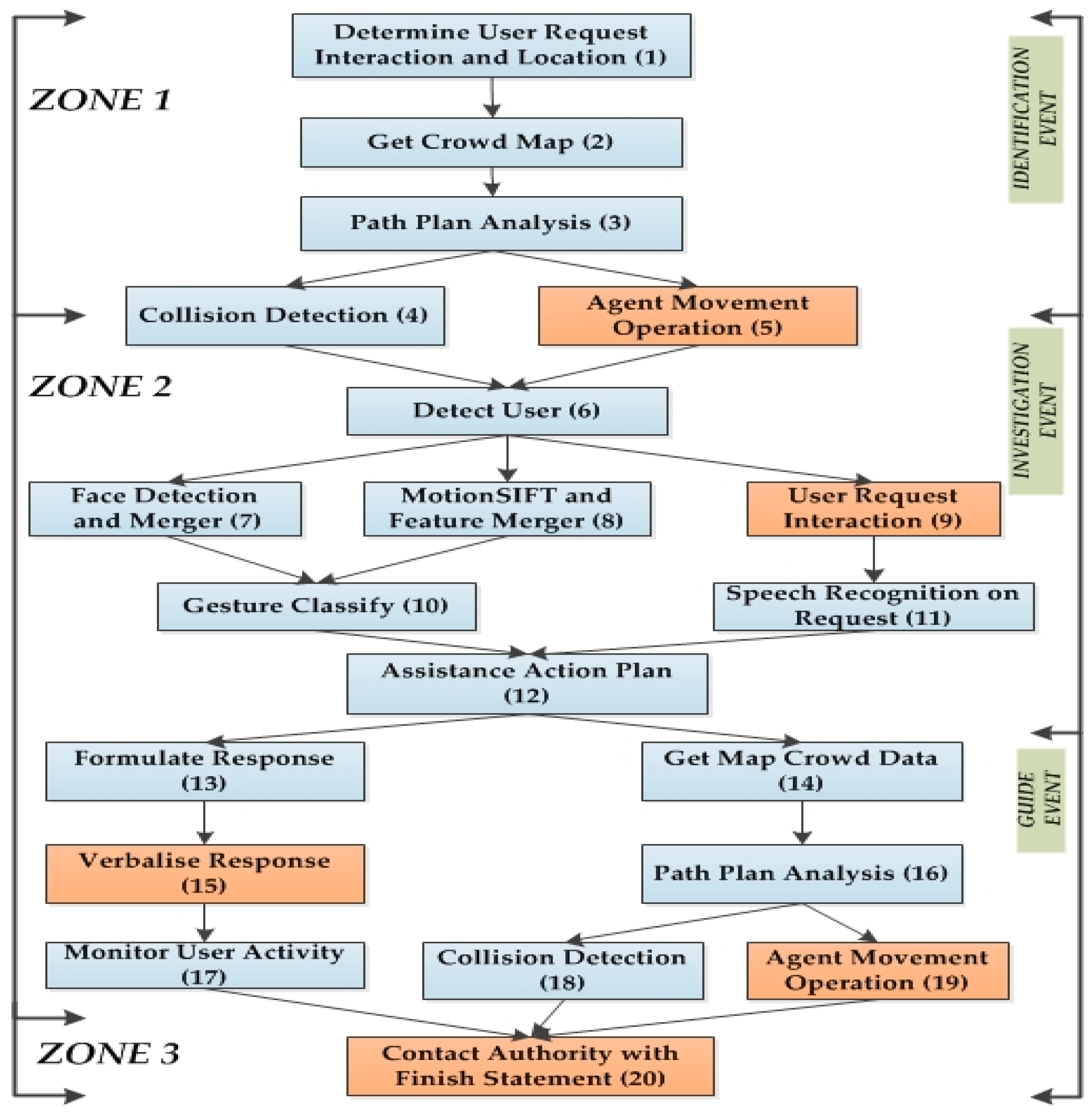
Table 3, along with two benchmarks for comparison. As seen from the table, an offloading decision for each task is provided. For the simulation, 13 tasks take place onboard the robot (represented by “1”), which means seven tasks have been offloaded (represented by “0”). As the task allocation result is presented in a serial, the seven offloaded tasks (Tasks 3, 4, 6, 8, 12, 16, and 18) can clearly be identified. This is the optimal offloading decision for each task of the task flow.
A further comparison with the ES helps to verify the accuracy of the algorithm. We can observe that ES presents the minimal energy (2699.13 J), which is slightly better than the GA result. The situation is the same for the task completion time (51.74 s), which means that both algorithms manage to meet the delay constraint of 60 s. A more in-depth analysis shows that the reason for the difference in the value of minimal energy is the number of offloading decisions. The number of tasks offloaded for ES (8) is greater than GA (7). As a result, more offloading in ES provides the better value. However, GA provides the near-optimal result. Even though the results for minimal energy in ES are slightly better, it has some drawbacks. The major difference between the two methods is in the overhead. ES takes about 511.74 s to run the algorithm, which is more than 100 times the overhead time needed to run the GA (3.96 s). At the same time, the algorithm overhead energy for GA is 332.36 J. In the case of ES, the overhead energy is 3,4586.11 J, which is significantly higher. As the robot has limited energy, ES is definitely not a suitable option as it costs significantly more overhead time and more energy. From this point of view, the GA performs better for the proposed scenario as it provides a near-optimal result with a slight error in minimum energy, but significantly less overhead time.
We conduct another comparison for GA with an AoR (all-on-robot) approach. The results in Table 3 show that the processing energy (3802.23 J) of AoR is very high when compared with GA. More significantly, the task completion time in this case is 70.01 s, which does not meet the delay constraint. As AoR does not have any scope of adaptability, it is definitely not a suitable solution in this context. In contrast, the offloading approach to the cloud with GA provides more opportunities for the robot to adapt and complete the necessary tasks in cases when the AoR does not work.
Finally, we have evaluated the efficiency of the GA by calculating the “overall time”, which includes the GA overhead time as well as the task completion time. It is found that the overall time (56.36 s) is less than the overall time constraint of 60 s. So, it can be observed that in terms of overall energy, the GA-based scheme meets the delay constraint and is lower than the other benchmarks (463.46 s for EX and 70.01 s for AoR), as seen in Table 3. Even for the overall energy, the value of overall energy for the GA-based scheme is 3079.74 J, which is lower than both EX (3,7285.24 J) and AoR (3802.23 J).
Scenario 2 (Minimise: T t o t a l )
We run simulations for an alternative scenario where the objective is to minimise the time. Similar to the previous simulation, the downward trend of average fitness score (Figure 7) suggests that the GA is working properly. The lowest fitness score looks for lower fitness score to be replaced until finding the lowest one. For this scenario, it takes 651 simulations to find the minimum task completion time, which is a lot higher than the previous scenario. The optimal solution (Table 4) shows the eight tasks being offloaded (Tasks 3, 4, 6, 8, 12, 16, 17, 18, which are represented by “0”).
We also compare with ES and AoR to verify the performance. For ES, we get the exact same result as GA, which means it is an optimal result. As ES has a high overhead energy and time (55,552.2836 J and 661.34 s, respectively), it is not suitable. However, for GA, the overhead energy (838.53 J) and time (55,552.28 J) is around 60 times less. The results of AoR show that it takes 70.01 s to complete the task flow. Even though the total energy consumption (3802.23 J) meets the energy constraint, the method does not result in the minimum task completion time. Instead, a GA-based approach provides the best result (as shown earlier).
We have added an extra performance criterion to accommodate the GA overhead energy and time to the overall energy and time calculations. The objective here is to see if the added GA overhead can still maintain performance within the constraints. As seen from Table 4, the GA-based scheme provides overall energy of 3605.48 J, which is less than the energy constraints. It is also lower than the other benchmarks of EX (58,319.23 J) and AoR (3802.23 J). The same is found in the case of overall time. Ex takes 711.46 s and AoR takes 70.01 s, while the overall time for GA-based scheme is 60.82 s.
All the performance criteria (time, energy, overhead, etc.) in both scenarios point to the superiority of the genetic algorithm (GA)-based scheme over the other two benchmarks of Exhaustive Search (EX) and All on Robot (AoR) method.

5.2.1. Impact of Bandwidth (Minimise: T t o t a l )

In this section we have run simulations to check the impact of bandwidth on offloading decisions and system performance. The results are presented in Table 5. We considered Scenario 2 (Minimise: T t o t a l ) for running simulations of bandwidth change. As mentioned, we verified the adaptability of the GA-based scheme with respect to bandwidth. As different parts of the abovementioned application take place in different locations, we varied the bandwidth values for one of the zones/locations (Zone 2) to observe the effects of bandwidth change. We ran five different simulations and evaluated the results of the offloading decisions and minimum completion time.
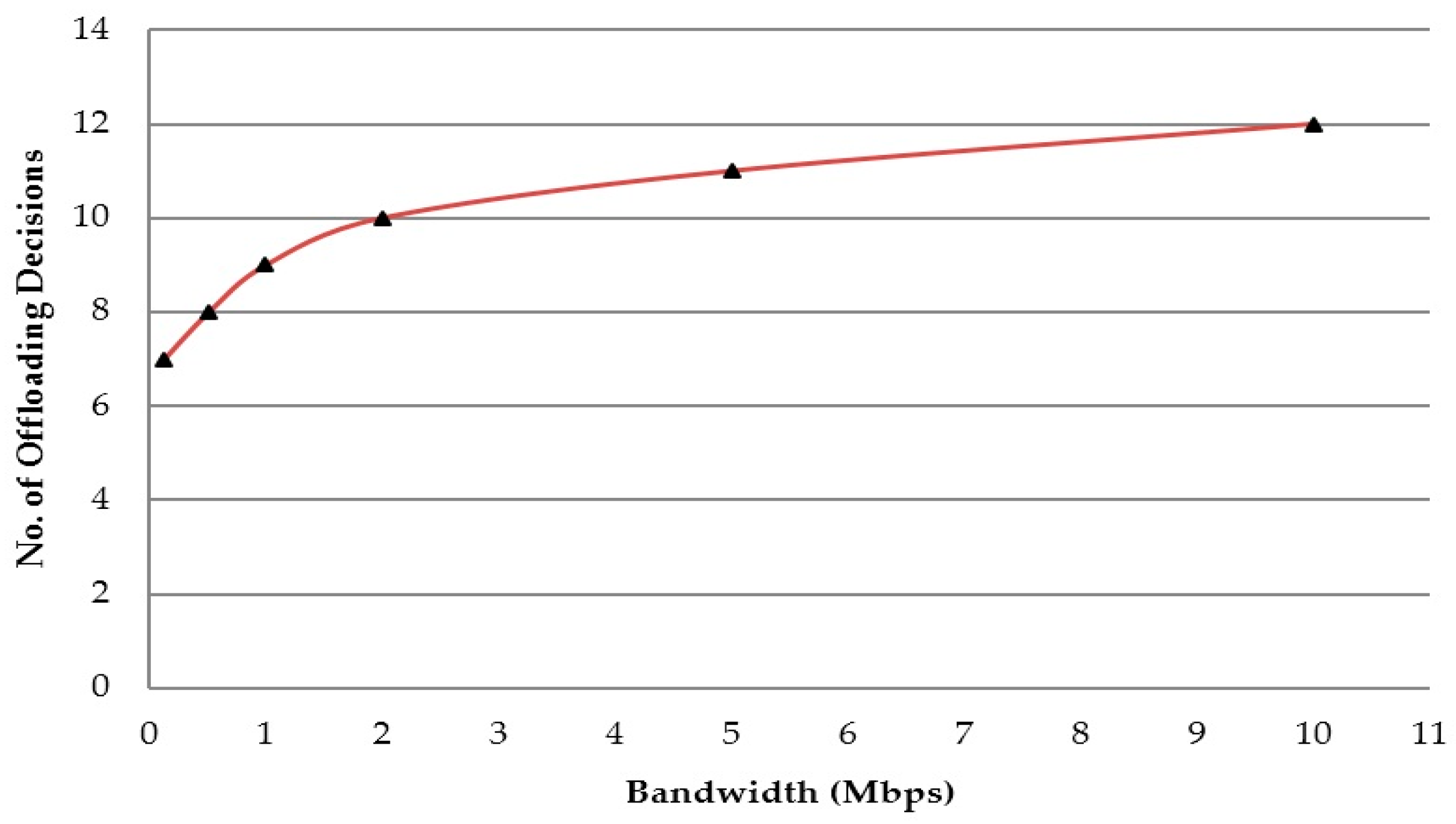
The results suggest a clear progression of offloading decisions with the increase in bandwidth (illustrated in 
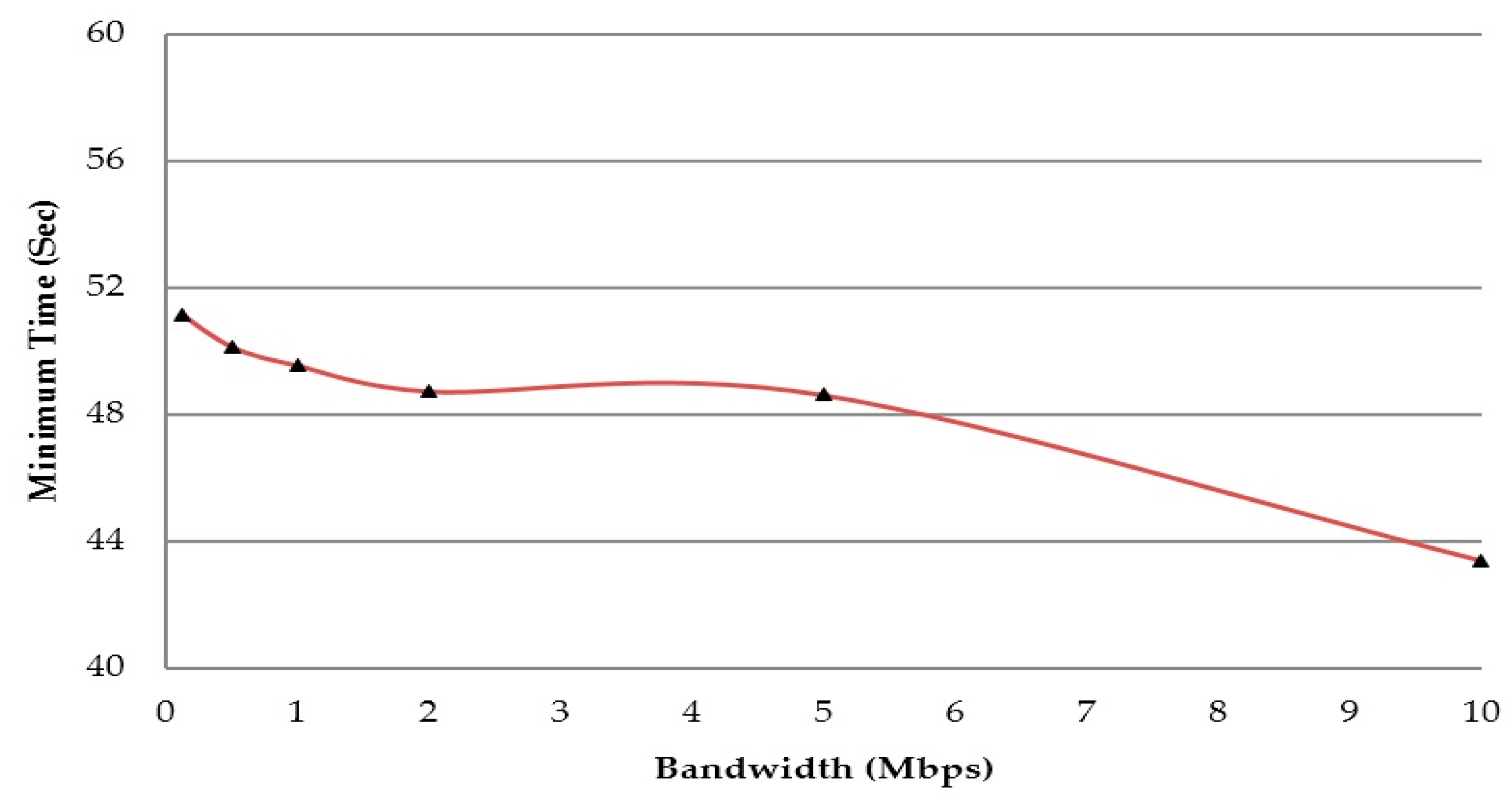
Figure 8). At the same time, the bandwidth increase also ensures a decline in overall task completion time for the robot (Figure 9). This indicates that better bandwidth enables the GA scheme to adapt to changing conditions and offload more tasks, which in turn decreases the minimum task completion time of the robot. It also means that bandwidth has a significant impact on the offloading decisions and thereby the overall performance. Similar results have been found for Scenario 1 (Minimise: E t o t a l ), where the GA adapts with changing bandwidth and provides more offloading options for tasks. Thus it manages to find the optimal offloading decisions that provide minimal energy while meeting the constraints.
This suggests that changing the bandwidth has a significant impact on offloading for robotics operations. As the robot has the ability to move, so this opens up this area for discussion regarding the impact of bandwidth and movement on performance as well as each other. A further study is required to analyse its impact and find ways to utilize it properly for improving system performance.

5.2.2. Impact of Movement (Minimise: E t o t a l )

To understand the impact of movement on the current scenario, we have selected scenario 1 (Minimise: E t o t a l ) to run simulations. The three zones in our problem set are represented by coordinates. We have changed the coordinates of one the zones (Zone 2) to increase the distance between Zone 1 and Zone 2. For that changing condition, we run simulations on two cases. In first case, the bandwidth of Zone 2 is 512 Kbps. This section explains the results for this particular case.
From the results in Table 6, we can see that there is an increasing trend for both energy and time. This means that the increase in distance between the zones causes more robotic energy consumption as the movement itself is a task that requires energy. This also increases the total completion time. As seen from the table, the total completion time becomes higher than the time constraint (60 s) after a certain amount of increase in distance. At that point, the robot fails to complete the tasks within the given constraints despite offloading seven tasks. For this simulation, this happens when the Zone 2 coordinates result in a distance of 54.43 units between Zone 1 and Zone 2. These results clearly show that movement has a significant impact on task offloading decisions for this scenario.

5.2.3. Impact of Movement and Bandwidth (Minimise: E t o t a l )

We further study the integrated impact of both bandwidth and movement in task offloading decisions. This also helps us to show how this can be used to our benefit. For the simulation results in Table 6, the first case (512 Kbps) presents a situation where the increasing distance causes the movement energy and time to become so high that the total completion time exceeds the constraints. Even though seven tasks were offloaded using available bandwidth (512 Kbps), it was still not enough.
To solve this situation, we ran simulations for a second case. In this case, everything remained the same except for the bandwidth of one of the zones (Zone 2). We increased the zone bandwidth to 5 Mbps. From the results, we can see that the performance improved much faster. For the same increase in distance, the robot managed to complete the task flow for all the simulations. Even when the distance increased to 54.43 units, it was within time constraint. This was possible because of better network connectivity, which meant faster offloading was possible. Also, the robot managed to offload nine tasks (more than in the other case), which also contributed to the improvement in results.
From the results and analysis, we can conclude that movement and bandwidth make a significant impact on task offloading decisions. In fact, as the latter case suggested, a proper trade-off between movement and bandwidth can actually overcome the shortcomings of the system and improve the system performance when necessary. In addition, pre-gathered knowledge about the bandwidth and the locations could be useful for the robot to plan paths for offloading and task completions. A future study will focus on implementations to make offloading decisions with movement, bandwidth, and paths as possible variables.

6. Multi-Task Flow Path Planning for Offloading

6.1. Problem Setup

In addition to the task offloading problem in the previous section, we have introduced a “travelling salesman problem” for multi-task flow optimal task sequencing in the given cloud robotics system. For this problem set, the robot is called upon to complete multiple task flows at the same time. In this scenario, each task flow needs to be completed within a given constraint (time) and with minimum energy by finding optimal offloading decisions. These different task flows are in different locations that the robot has to move to. So, it requires an optimal ordering of the task to make sure that all the tasks are completed successfully with minimum energy. As one of the main variable factors in this new problem is movement energy, the robot’s task ordering and its resulting movement (path planning) need to be optimal.
So, the objective is to complete all the task flows within the individual time constraints (for each task flow) while expending the individual minimum energy requirement. It also has to find the optimal task sequence to make sure that the cumulative energy for the task flows is minimal.

6.2. Mathematical Implementation

For our scenario, we assume that the robot is asked to complete K number of task flows at a given moment. Each task flow is represented by W. For task flow, W = 1...K, the robot needs to find the optimal task ordering sequence resulting in movement to the corresponding zones. Here the term C E signifies the cumulative Energy for all the task flows. So,
C E   = W = 1 K W E t o t a l .
In this equation, the term W E t o t a l points to the total energy for each of the given task flows. As mentioned before, for each of the task flows the robot needs to find the optimal offloading decisions to meet the time constraint and find the minimum energy. In the previous section we presented our GA-based offloading scheme to solve the task offloading problem. On top of that, we add this scenario where the robot needs to complete all these task flows by moving to their given locations. As different task flows are taking place in different start and finish locations, it compels the robot to plan its sequence for moving to these various locations in a specific order to expend the minimum cumulative energy. Let O w indicate optimal order of task sequence of the task flows. So the objective of this problem is,
Find  :   {   O w   }  for  { w = 1 : K }  to
Minimise :   C E   ,
where each of the task flows solves the task offloading optimization problem according to the GA-based scheme mentioned in the previous sections.

6.3. Workspace Setup and Methodology

As presented in the workspace in Figure 10, each of the task flows requires the robot to first move from the current location to a given location, which is known as the investigation phase. As the robot moves to the new location, the investigation (I) phase begins. This is followed by the final phase, where the robot initiates the guide (G) event to move to the final destination. So, for each task flow the robot completes its tasks in three separate zones (depending on the task flow locations). However, in some cases, the finishing location of one phase may be the starting location of next phase. In that case, the movement and its corresponding energy are considered to be 0. The location information for each of the task flows is presented in Figure 10.
For this given workspace, the robot needs to find the optimal task sequence for movement. To solve this problem, we initially run a GA-based algorithm for each of the task flows to find the optimal offloading decisions that meet the constraints and require the minimum energy. In addition, we run an exhaustive search to check all the possible combinations of the given task sequence. During this stage, it is important to keep track of the movement of the robot, as the ending location of one of the task flows is the starting point for the next task flow. We also calculate the cumulative energy ( C E ) and compare it with the other possible solutions to find the lowest one. At the end of the calculation, O w represents the optimal sequence of tasks that results in the lowest C E .

6.4. Simulation Setup and Results

For the simulation we consider the number of task flows, K = 5. Each of the task flows has two locations (I and G) for investigation and guide event phases. The starting location of the robot, S = (1.71, 3.32). The movement energy and time between each location (represented by coordinates) can be found from Equations (9) and (16), respectively. The complete workspace is divided into six zones. Each zone has its separate bandwidth (or no Internet). The available bandwidth is a critical factor for the robot in that location to communicate with the cloud. The information regarding the available bandwidth at each location is presented in Figure 10. Moreover, all of the locations for the task flows are associated with different zones. Based on all that information, a simulation is run to find the optimal task sequence. This means that the robot finds the optimal order in which to move so as to minimise the cumulative energy.
The results from the simulation are depicted in Figure 10. We also provide the results for optimal offloading decisions of each of the task flows (that meet their respective constraint). The results in Table 7 present the performance of each of the task flows with respect to their own constraints for optimization. As the GA-based algorithm was implemented (as in the previous section), the results provide the optimal offloading decision. Depending on the location of the tasks, the number of offloaded tasks may vary. For example, Task flow 2 consists of an investigation phase in Zone 7, which has a bandwidth of 1 Mbps. This is reflected in the offloading decisions, with nine tasks being offloaded. On the other hand, Task flow 3 starts in Zone 6, which has no Internet connection. As a result, all the tasks are done on the robot, which impacts the performance significantly (high value for optimal energy as well as the constraint). These suggest the bandwidth has major impact.
In the second part (Table 8), we present the results for optimal task sequence for the multi-task flow offloading problem. Figure 10 presents the task sequence visually. It depicts the optimal path from the starting position to the end of the set of task flows. From the exhaustive search, we get the optimal combination for task sequence. It suggests the desired order to be: (Task 1--->Task 4---> Task 5---> Task 2---> Task 3) as seen in Table 8. Here the minimal cumulative energy of the task set sequence is 28713.3923 J. In this way, the robot plans the optimal path to move in order to complete the set of task flows via task offloading. This presents a scenario where task offloading, movement, path planning, and bandwidth have been integrated with our task flow for a given scenario in smart city.

7. Current Trends

Cloud robotics is a recent topic that has lots of avenues for exploration. The on-demand computation support and the available storage space make it an attractive component of investigation. Even though research into networked robotics with additional web support can be dated to the late 1990s, the concept is slowly reaching its peak in recent times. In relation to some of the recent references found in the literature, most of the relevant ones are on different cloud computing models. Due to the high demand for computing resources from service providers, the computing industry has shifted towards providing different application-oriented services. For example, DAvinCi uses the Software-as-a-Service (SaaS) model for simultaneous localization and mapping (SLAM) [19]. Recently, CORE has utilized the SaaS for a distributed and scalable cloud-enabled architecture for object recognition [20]. Alternatively, Platform-as-a-Service (PaaS) is a model used by Rapyuta [21] for applications like RoboEarth that uses cloud for robot knowledge sharing. In our work, we use PaaS to access the available software platform and build on that.
A few optimization studies on cloud robotics have recently looked at autonomic systems. Pandey et al. [22] worked on optimization of resource allocation for tasks in an underwater mobile sensor network by implementing a dynamic and reliable collaboration between an autonomous underwater vehicle (AUV) network and the cloud data centre. Wang et al., in [23], presented a real-time multi-sensor data retrieval for cloud robotics systems, which is also formulated as an optimization problem that is solved using a Stackelberg game-based retrieval management mechanism. The mobile cloud and the robot cloud share similarity to some extent since robots typically interact with other services in the cloud through wireless communication. Our proposed framework enables task offloading to the cloud and is motivated by the optimal task offloading method presented by Kao and Krishnamachari in [24,25] for the field of mobile cloud offloading. However, they did not consider any practical applications in their system. Contrary to that, we have presented scope for a wider range of smart city applications as well as focusing on a fixed application of crowd control. Moreover, cloud robotic agents have added features of movement. The mobility of the robot can be used for making on-demand movement to different locations for actuating tasks. This adds more dimensions to the scenario and leads to a more challenging problem set.
We consider the smart city our crowd control as our domain for cloud robotic application. The smart city itself has ample possibilities for application and implementation that have prompted some research initiatives. One of the initial studies has looked into the scope of the application and various design complications. For example, Gaur et al. [26] and Wenge et al. [27] have worked on different designs and implementation challenges for smart city applications.
There have also been instances of application setup and their performance evaluation. For example, Jeong et al. [28] proposed a city-wide wireless sewer sensor network can be made intelligent by having parasitic slot array manhole cover antennas. Gomez and Paradells [29] studied the Urban Automation Network (UAN) in the smart city and assessed its properties and trade-offs. Leccese et al. [30] field tested a fully remote controlled street lighting aisle of lamp posts that has been designed to perform various activities to physically control the lamp posts and transmit information by remote control. All these examples of smart city applications differ from ours in scope and field of application.
Calavia et al. [31] present a proposal for an intelligent video surveillance system that is designed to minimise video processing and transmission, which allows a large number of cameras to be deployed on the system, and therefore make it suitable for use as an integrated safety and security solution in smart cities. However, they only specify one aspect of the work, which is sensor-based surveillance. In our work, we propose an automated robot service that is equipped to take necessary action based on surveillance done by sensor camera networks.
Finally, Ermacora et al. [32] give references for a cloud-based automated approach that leads to applications in smart city robotic system. This is followed up by a presentation of a cloud robotics architecture for emergency management and monitoring services by Ermacora et al. in [33]. However, their application focuses on the implementations of Unmanned Aerial Vehicles (UAVs), which is different from ours. We focus on the proposed cloud robotics framework for service-based applications (such as a crowd control system) by automated ground robots.

8. Conclusions

In this paper, we propose a cloud robotics framework where robotic agents can leverage the cloud services to improve system performance and QoS. The major contribution of the paper is an integrated system of WSN, robotic network, and cloud infrastructure for smart city crowd control. We present an optimization problem for a typical system task flow (known as DAG). A GA-based scheme is then adopted (in two scenarios) to find the optimal offloading decisions while meeting the system constraints. The results show the advantage of GA (i.e., optimal or near-optimal result with less overhead) over the other presented benchmarks. We also vary the bandwidth and movement to highlight the adaptability of our algorithm in a changing environment along with the impact of these factors exclusively in this field. Finally, a simulation for a multi-task flow task sequence optimization has been made that suggests that task offloading and path planning can be integrated by varying distance (movement) and bandwidth. For future work, the robot path planning and bandwidth estimation can be further studied and integrated into an optimization problem with a view to further enhancing our system performance.

Acknowledgments

This work was partially supported by Swinburne University of Technology under the Early Research Career Scheme 2014. The authors would also like to thank Phillip Smith for his input.

Author Contributions

This paper has been written by Akhlaqur Rahman and is based on the research conducted by him under the supervision of Jiong Jin and co-supervision of Antonio Cricenti. Guidance related to simulation has been provided by Ashfaqur Rahman. Marimuthu Palaniswami and Tie Luo helped in drafting the paper with their expertise and experience.

Conflicts of Interest

The authors declare no conflict of interest.

References

  1. Colas, F.; Mahesh, S.; Pomerleau, F.; Liu, M.; Siegwart, R. 3D path planning and execution for search and rescue ground robots. In Proceedings of the 2013 IEEE/RSJ International Conference on Intelligent Robots and Systems (IROS), Tokyo, Japan, 3–7 November 2013; pp. 722–727.
  2. Liu, M.; Siegwart, R. Navigation on point-cloud—A riemannian metric approach. In Proceedings of the 2014 IEEE International Conference on Robotics and Automation (ICRA), Hong Kong, China, 31 May–7 June 2014; pp. 4088–4093.
  3. Liu, M.; Colas, F.; Oth, L.; Siegwart, R. Incremental topological segmentation for semi-structured environments using discretized GVG. Auton. Robot. 2014, 38, 143–160. [Google Scholar] [CrossRef]
  4. Ghodoussi, M. Transforming a surgical robot for human telesurgery. IEEE Trans. Robot. Autom. 2003, 19, 818–824. [Google Scholar]
  5. Mell, P.; Grance, T. The nist definition of cloud computing. NIST Spec. Publ. 2011, 800, 145. [Google Scholar]
  6. Hu, G.; Tay, W.P.; Wen, Y. Cloud robotics: Architecture, challenges and applications. IEEE Netw. 2012, 26, 21–28. [Google Scholar] [CrossRef]
  7. Jin, J.; Gubbi, J.; Marusic, S.; Palaniswami, M. An information framework for creating a smart city through internet of things. IEEE Int. Things J. 2014, 1, 112–121. [Google Scholar] [CrossRef]
  8. Moss Kanter, R.; Litow, S.S. Informed and Interconnected: A Manifesto for Smarter Cities; Harvard Business School General Management Unit Working Paper; Harvard Business School: Boston, MA, USA, 2009. [Google Scholar]
  9. Harrison, C.; Eckman, B.; Hamilton, R.; Hartswick, P.; Kalagnanam, J.; Paraszczak, J.; Williams, P. Foundations for smarter cities. IBM J. Res. Dev. 2010, 54, 1–16. [Google Scholar] [CrossRef]
  10. Mitton, N.; Papavassiliou, S.; Puliafito, A.; Trivedi, K.S. Combining cloud and sensors in a smart city environment. EURASIP J. Wirel. Commun. Netw. 2012, 2012, 1–10. [Google Scholar] [CrossRef]
  11. Gubbi, J.; Buyya, R.; Marusic, S.; Palaniswami, M. Internet of things (iot): A vision, architectural elements, and future directions. Future Gener. Comput. Syst. 2013, 29, 1645–1660. [Google Scholar] [CrossRef]
  12. Yuan, D.; Jin, J.; Grundy, J.; Yang, Y. A framework for convergence of cloud services and internet of things. In Proceedings of the 2015 IEEE 19th International Conference on Computer Supported Cooperative Work in Design (CSCWD), Calabria, Italy, 6–8 May 2015; pp. 349–354.
  13. Foster, I.; Zhao, Y.; Raicu, I.; Lu, S. Cloud computing and grid computing 360-degree compared. In Proceedings of the Grid Computing Environments Workshop (GCE’08), Austin, TX, USA, 12–16 November 2008; pp. 1–10.
  14. Rahman, A.; Jin, J.; Cricenti, A.; Rahman, A.; Yuan, D. A cloud robotics framework of optimal task offloading for smart city applications. In Proceedings of the Global Communication Conference (IEEE Globecom 2016), Washington, DC, USA, 4–8 December 2016.
  15. Konak, A.; Coit, D.W.; Smith, A.E. Multi-objective optimization using genetic algorithms: A tutorial. Reliab. Eng. Syst. Saf. 2006, 91, 992–1007. [Google Scholar] [CrossRef]
  16. Mitchell, M. An Introduction to Genetic Algorithms; MIT Press: Cambridge, MA, USA, 1998. [Google Scholar]
  17. Corrêa, R.C.; Ferreira, A.; Rebreyend, P. Scheduling multiprocessor tasks with genetic algorithms. IEEE Trans. Parallel Distrib. Syst. 1999, 10, 825–837. [Google Scholar] [CrossRef]
  18. Zhang, W.; Tan, S.; Lu, Q.; Liu, X.; Gong, W. A genetic-algorithm-based approach for task migration in pervasive clouds. Int. J. Distrib. Sens. Netw. 2015, 2015, 9. [Google Scholar] [CrossRef]
  19. Arumugam, R.; Enti, V.R.; Bingbing, L.; Xiaojun, W.; Baskaran, K.; Kong, F.F.; Meng, K.D.; Kit, G.W. Davinci: A cloud computing framework for service robots. In Proceedings of the 2010 IEEE International Conference on Robotics and Automation (ICRA), Anchorage, AK, USA, 3–8 May 2010; pp. 3084–3089.
  20. Beksi, W.J.; Spruth, J.; Papanikolopoulos, N. Core: A cloud-based object recognition engine for robotics. In Proceedings of the 2015 IEEE/RSJ International Conference on Intelligent Robots and Systems (IROS), Hamburg, Germany, 28 September–2 October 2015; pp. 4512–4517.
  21. Hunziker, D.; Gajamohan, M.; Waibel, M.; D’Andrea, R. Rapyuta: The roboearth cloud engine. In Proceedings of the 2013 IEEE International Conference on Robotics and Automation (ICRA), Karlsruhe, Germany, 6–10 May 2013; pp. 438–444.
  22. Pandey, P.; Pompili, D.; Yi, J. Dynamic collaboration between networked robots and clouds in resource-constrained environments. IEEE Trans. Autom. Sci. Eng. 2015, 12, 471–480. [Google Scholar] [CrossRef]
  23. Wang, L.; Liu, M.; Meng, M.Q.-H. Real-time multisensor data retrieval for cloud robotic systems. IEEE Trans. Autom. Sci. Eng. 2015, 12, 507–518. [Google Scholar] [CrossRef]
  24. Kao, Y.-H.; Krishnamachari, B. Optimizing mobile computational offloading with delay constraints. In Proceedings of the Global Communication Conference (Globecom 14), Austin, TX, USA, 8–12 December 2014; pp. 8–12.
  25. Kao, Y.-H.; Krishnamachari, B.; Ra, M.R.; Bai, F. Hermes: Latency optimal task assignment for resource-constrained mobile computing. In Proceedings of the 2015 IEEE Conference on Computer Communications (INFOCOM), Hong Kong, China, 26 April–1 May 2015; pp. 1894–1902.
  26. Gaur, A.; Scotney, B.; Parr, G.; McClean, S. Smart city architecture and its applications based on iot. Procedia Comput. Sci. 2015, 52, 1089–1094. [Google Scholar] [CrossRef]
  27. Wenge, R.; Zhang, X.; Dave, C.; Chao, L.; Hao, S. Smart city architecture: A technology guide for implementation and design challenges. China Commun. 2014, 11, 56–69. [Google Scholar] [CrossRef]
  28. Jeong, S.; Chappell, W.J. A city-wide smart wireless sewer sensor network using parasitic slot array antennas. IEEE Antennas Wirel. Propag. Lett. 2010, 9, 760–763. [Google Scholar] [CrossRef]
  29. Gomez, C.; Paradells, J. Urban automation networks: Current and emerging solutions for sensed data collection and actuation in smart cities. Sensors 2015, 15, 22874–22898. [Google Scholar] [CrossRef] [PubMed] [Green Version]
  30. Leccese, F.; Cagnetti, M.; Trinca, D. A smart city application: A fully controlled street lighting isle based on Raspberry-Pi card, a ZigBee sensor network and WiMAX. Sensors 2014, 14, 24408–24424. [Google Scholar] [CrossRef] [PubMed]
  31. Calavia, L.; Baladrón, C.; Aguiar, J.M.; Carro, B.; Sánchez-Esguevillas, A. A semantic autonomous video surveillance system for dense camera networks in smart cities. Sensors 2012, 12, 10407–10429. [Google Scholar] [CrossRef] [PubMed]
  32. Ermacora, G.; Rosa, S.; Bona, B. Sliding autonomy in cloud robotics services for smart city applications. In Proceedings of the Tenth Annual ACM/IEEE International Conference on Human-Robot Interaction Extended Abstracts, Portland, OR, USA, 2–5 March 2015; pp. 155–156.
  33. Ermacora, G.; Toma, A.; Bona, B.; Chiaberge, M.; Silvagni, M.; Gaspardone, M.; Antonini, R. A cloud robotics architecture for an emergency management and monitoring service in a smart cityenvironment. In Proceedings of the 2013 IEEE/RSJ International Conference of Intelligent Robots and Systems (IROS), Tokyo, Japan, 3–7 November 2013.
Figure 1. A smart city cloud robotics framework.
Jsan 05 00020 g001
Figure 2. An operation task flow of smart city crowd control.
Jsan 05 00020 g002
Figure 3. A flow-chart of the genetic algorithm based scheme.
Jsan 05 00020 g003
Figure 4. Pseudo-code for calculating the total robotic energy.
Jsan 05 00020 g004
Figure 5. Pseudo-code for calculating the total task completion time/delay.
Jsan 05 00020 g005
Figure 6. Performance graph of 20-node task flow (Minimise: E t o t a l ).
Jsan 05 00020 g006
Figure 7. Performance graph of 20-node task flow (Minimise: T t o t a l ).
Jsan 05 00020 g007
Figure 8. Impact of bandwidth change on offloading decisions (min: T t o t a l ).
Jsan 05 00020 g008
Figure 9. Impact of bandwidth change on minimum task completion time (min: T t o t a l ).
Jsan 05 00020 g009
Figure 10. Optimal task sequence for a multi-task flow offloading problem.
Jsan 05 00020 g010
Table 1. Notation.
Table 1. Notation.
E t o t a l = Total robotic energy consumption for execution of the task flow
T t o t a l = Total execution time of the task flow
T D e a d l i n e = Total allocated time for the execution of the task flow
E L i m i t = Energy consumption limit for the execution of the task flow
β = Amount of bandwidth
N ( t i ) = Number of instruction for task t i
d u ( t i ) = Amount of uploaded data for task t i
d d ( t i ) = Amount of collected data for task t i
BPI = Bits per instruction
C P I = Average number of clock cycles per instruction
S r = Clock speed of robot
S c = Clock speed of VM on cloud
Table 2. Simulation parameter setup for the 20-node task flow.
ParameterMinimise E t o t a l Minimise T t o t a l
ConstraintTime (60 s)Energy (4000 J)
Population Size50100
BandwidthZone 1Zone 2Zone 3
256 Kbps512 Kbps128 Kbps
Task ConstraintTasks 5, 9, 15, 19, and 20 must be done by the robot
Stopping Criteria300 Generation without change
Table 3. Performance comparison for 20-node task flow (Minimise: E t o t a l ).
Result ParametersGenetic AlgorithmExhaustive SearchAll on Robot
Generation No371N/AN/A
Offloading Decisions (1-Robot) (0-Cloud)1 1 0 0 1 0 1 0 1 1 1 0 1 1 1 0 1 0 1 11 1 0 0 1 0 1 0 1 0 1 0 1 1 1 0 1 0 1 11 1 1 1 1 1 1 1 1 1 1 1 1 1 1 1 1 1 1 1
Offloaded Task780
Minimum Energy ( E t o t a l )2746.98 J2699.13 J3802.23 J
Completion Time52.40 s51.74 s70.01 s
GA Overhead Time3.96 s411.72 sN/A
GA Overhead Energy332.36 J34586.11 JN/A
Overall Time= Completion Time + GA Overhead Time56.36 s463.46 s70.01 s
Overall Energy = Completion Energy + GA Overhead Energy3079.74 J37285.24 J3802.23 J
Table 4. Performance comparison for 20-node task flow (Minimise: T t o t a l ).
Result ParametersGenetic AlgorithmExhaustive SearchAll on Robot
Generation No651N/AN/A
Offloading Decision (1-Robot) (0-Cloud)1 1 0 0 1 0 1 0 1 1 1 0 1 1 1 0 0 0 1 11 1 0 0 1 0 1 0 1 1 1 0 1 1 1 0 0 0 1 11 1 1 1 1 1 1 1 1 1 1 1 1 1 1 1 1 1 1 1
Offloaded Task880
Minimal Time ( T t o t a l )50.12 s50.12 s70.01 s
Total Energy2766.95 J2766. 95 J3802.23 J
Overhead Time10.70 s661.34 sN/A
Overhead Energy838.53 J55,552.28 JN/A
Overall Energy = Completion Energy + GA Overhead Energy3605.48 J58319.23 J3802.23 J
Overall Time = Completion Time + GA Overhead Time60.82 s711.46 s70.01 s
Table 5. Impact of bandwidth change on task offloading.
Bandwidth of Zone 2 (Mbps)Minimum Time (Sec)Total Robotic Energy (J)Task Allocation (1-Robot) (0-Cloud)Offloaded Task No.
0.12851.152870.411 1 0 0 1 0 1 0 1 1 1 0 1 1 1 0 1 0 1 17
0.51250.122766.951 1 0 0 1 0 1 0 1 1 1 0 1 1 1 0 0 0 1 18
149.542720.211 1 0 0 1 0 1 0 1 1 0 0 1 1 1 0 0 0 1 19
248.733519.531 1 0 0 1 0 1 0 1 1 0 0 1 0 1 0 0 0 1 110
548.612985.041 1 0 0 1 0 1 0 1 0 0 0 1 0 1 0 0 0 1 111
1043.392689.871 1 0 0 1 0 0 0 1 0 0 0 1 0 1 0 0 0 1 112
Table 6. Impact of movement on offloading decisions and system performance.
Zone Locations (x, y)Distance between Zone 1 and Zone 2 (Units)Case 1: Zone 2 Bandwidth (512 Kbps)Case 2: Zone 2 Bandwidth (5 Mbps)
Minimal Energy (J)Total Time (s)Offloading DecisionsMinimal Energy (J)Total Time (s)Offloading Decisions
Zone 1: (7.70,9.31)6.082746.9850.391 1 0 0 1 0 1 0 1 1 1 0 1 1 1 0 1 0 1 1 (7 Tasks Offloaded)2661.4549.331 1 0 0 1 0 1 0 1 0 0 0 1 1 1 0 1 0 1 1 (9 Tasks Offloaded)
Zone 2: (2.08,11.65)
Zone 1: (7.70,9.31)14.562882.7452.092797.2151.02
Zone 2: (22.08,11.65)
Zone 1: (7.70,9.31)34.463200.9956.073115.4655.01
Zone 2: (42.08,11.65)
Zone 1: (7.70,9.31)54.43N/AN/A3435.0159.01
Zone 2: (62.08,11.65)
Table 7. Performance for GA-based task offloading for each task flow (minimise: E t o t a l ).
Task Flow SetCoordinates (x, y)Optimal Energy (J)Total Time (s)Task AllocationTask Offload No.
[S-Starting Phase]
[I-Investigative Phase]
[G-Guide Event Phase]
1I = (10.21, 72.4) [Zone 5]5339.8192.241 1 1 1 1 0 0 0 1 1 0 0 1 1 1 0 0 0 1 18
G = (51.12, 41.2) [Zone 3]
2I = (32.1, 60.3) [Zone 7]5243.2290.881 1 1 1 1 0 0 0 1 0 0 0 1 1 1 0 0 0 1 19
G = (56.3, 96.1) [Zone 8]
3I = (56.3, 96.1) [Zone 8]8121.15139.291 1 1 1 1 1 1 1 1 1 1 1 1 1 1 1 1 1 1 10
G = (16.09, 16.65) [Zone 2]
4I = (30.42, 3.11) [Zone 3]4669.3983.711 1 1 1 1 0 0 0 1 1 0 0 1 1 1 0 0 1 1 17
G = (30.42, 3.11) [Zone 6]
5I = (10.21, 72.4) [Zone 5]5276.8195.531 1 1 1 1 0 0 0 1 1 0 0 1 1 1 0 0 0 1 18
G = (71.12, 21.2) [Zone 4]
Table 8. Simulation results for multi-task flow optimal task sequence problem.
Optimal Task Set Sequence: [Task 1--->Task 4---> Task 5---> Task 2---> Task 3]
Minimal Energy of Task Set Sequence: 28713.3923 J
Optimal Time of Task Set Sequence: 498.3585 s

