1. Introduction
In industrial facilities, distributed Sensors and Actuators (S&A) are networked by means of the so-called fieldbuses. These digital communication networks fulfill necessities that process automation imposes like real-time and reliability [
1]. Other nodes also integrated in the networks are controllers and supervisory systems, aiming to share the operational information compulsory for the proper behavior of the process.
Aiming at improving communication quality and costs in comparison to previous analog communication buses [
2], fieldbuses have evolved since their inception from simple and proprietary approaches to heterogeneous communication infrastructures where wired and wireless networks coexist [
3]. Different topologies, even combining diverse fieldbuses protocols, can be deployed, where several already standardized protocols contribute to enhance the interoperability handling [
4]. Some examples of well-known fieldbuses are the Actuator Sensor Interface (AS-i), Modbus, Controller Area Network (CAN), PROcess FIeld BUS (PROFIBUS), PROcess FIeld NETwork (PROFINET), and Ethernet for Control Automation (EtherCAT).
Relating to Ethernet, when Internet technology became popular, a new wave of Ethernet-based networks was stimulated for automation [
3]. Advances in Ethernet technology have made the medium more suited to industrial use, resulting in a trend towards Ethernet-based fieldbus protocols [
5]. For years, Ethernet networks have become more and more popular due to advantages like speed, bandwidth, and easy integration with the Internet or the office network, among others. Ethernet is signalled as the basis for advances in industrial communications and standardization of industrial protocols [
6]. In fact, real time Ethernet has become a standard in the industrial automation domain [
3]. Improvements in industrial networking such as the incorporation of Ethernet technology have started to blur the line between industrial and commercial networks [
5]. This also allows for easier interconnection between business and industrial networks in order to relay process and control information to interested parties [
5].
These industry-focused networks also accommodate S&A for scopes out of the industrial domain, for instance, to implement remote laboratories [
4,
7], intelligent energy grids, i.e., Smart Grids (SGs) [
8,
9], or building automation systems [
2,
10].
Moreover, the increasing complexity of industrial systems results in a growing amount of data from signal sources that must be acquired, communicated, and evaluated [
11]. This data is commonly managed by Supervisory Control and Data Acquisition (SCADA) systems. These are software applications responsible for gathering the data provided by S&A, as well as exchanging control parameters with the automation units, i.e., Programmable Logic Controllers (PLC). Numerical and/or graphical information of the plant behavior is displayed in real time to an operator, and the relevant variables are stored for further analysis [
12].
Advanced functionalities are delivered as a consequence of the aforesaid complexity of industrial systems and the integration of Information and Communications Technologies (ICTs). In fact, a new industrial revolution is being predicted a-priori [
13], the Industry 4.0 (I4.0). Industrial Internet of Things (IIoT) is an alternative term to refer to such a paradigm. I4.0 is considered the fourth industrial revolution in which digital factories are conceived as smart environments where machines, sensors, and actuators are interconnected to enable collaboration, monitoring, and control [
14]. The implications of I4.0 are not only technological; it also involves economic, social, and ecological aspects [
15]. Various pillars of I4.0 are proposed in the literature, among which common features are networked interconnection of the components, massive data gathering and analytics, wide-adoption of ICTs, interoperability management, smart S&A, collaborative robotics, new business models, and cloud computing exploitation, just to name a few [
16].
I4.0 reshapes industry boundaries, creates entirely new industries, and exposes established manufacturing companies to new competitive challenges [
15]. Regarding the latter issue, notwithstanding that I4.0 is envisioned to facilitate interconnection and computerization into the traditional industry [
17], a big challenge facing I4.0 real-scale implementation is the legacy barrier. This is due to the fact that automation-devoted devices, mainly PLC, are expected to have a lifespan of decades, so the advents of innovative technology like those brought by I4.0, strike the legacy of already existing facilities. As it is evident, the investments associated with the modernization of software and hardware entities are a serious obstacle. Actually, most enterprises refuse a radical modernization of their entire automation system or simply cannot take the risk of quitting a running system.
Thus, the integration of the new advanced components within production systems requires a sound migration path from legacy production systems toward the improved production systems [
18]. This way, aiming at facilitating migration to the I4.0, a step-by-step process must be followed. Instead of changing the whole system, it is necessary to extend capabilities of the hardware infrastructure that is in use to implement modern ways of information management [
19]. Due to the networked operation, in I4.0, machinery and equipment must be provided with data sharing mechanisms [
20]. In other words, connectivity is a key feature for the legacy of already existing infrastructures; therefore, a first stage to be I4.0-ready consists of adding network connectivity to current devices.
Concerning PLC, their capabilities are continuously increasing according to technological advances in electronics and communications [
4]. Even modern units are being manufactured with an inbuilt Ethernet port, facilitating their integration into Ethernet-based networks.
Among the Research and Development (R&D) lines carried out in the Automation and Industrial Computation Laboratory of the University of Extremadura (Spain), I4.0 is receiving a lot of attention in order to study its implications from the perspective of automation and supervision. With this aim, an experimental advanced I4.0-compliant system is required to act as a benchmark to investigate the migration of legacy systems towards this challenging concept.
Within such a laboratory, a Flexible Manufacturing System (FMS) is found. It is composed of a set of stations interconnected mechanically by means of a transport conveyor, and logically through a fieldbus. Such a network acts as backbone where S&A, control units, and a supervisory system exchange data in real time. FMS has a modular architecture that allows the work stations to be reorganized for different processes and operations. As it is evident, FMS are ideal environments in which to research the I4.0 concept since they include characteristics like networked interconnection, data gathering, and distributed intelligence.
FMS are used nowadays in diverse R&D activities, as demonstrated by recently published papers. Girbea et al. [
21] use an FMS as an environment to research production scheduling and systems integration. In [
22], the application of the open source Arduino microcontroller in FMS is analysed. FMS as a scenario for a scheduling problem solved by means of Petri Nets is presented in [
23]. An FMS serves as the application case of an I4.0-compliant architecture proposed by Pisching et al. [
24]. In [
25], a proposal of human-machine cooperation approach in the context of I4.0 is evaluated using an FMS. Many papers reporting the utilization of FMS scarcely provide details about the real and effective automation and management of all involved equipment. However, this information constitutes useful insights for researchers and practitioners aiming to implement advanced frameworks.
This paper presents the first step for the migration of a legacy system, an FMS, towards the I4.0 concept. Namely, an Ethernet-based communication solution has been developed in order to integrate the S&A network and the SCADA system. This approach is conceived as a middle layer involving hardware and software elements.
The motivation for this work arose when implementing the automation system of the FMS in order to be exploited for I4.0-related R&D. It was necessary to improve some functionality of the FMS, mainly enhancing its networked communication options and data management. Concretely, the installed PLC do not provide Ethernet connectivity by default, whereas the fieldbus PROFIBUS is natively supported, as well as a proprietary protocol of Siemens (Multi-Point Interface, MPI). A SCADA system could be linked to the S&A network via MPI connection or using a PROFIBUS adaption card coupled to the PC where the supervisory application runs. Though, in a certain sense, under the I4.0 vision, these options imply an isolated operation regarding modern devices which use widespread Ethernet communication and facilitate the inclusion of other I4.0 functionalities. This boundary was considered as an opportunity to study the legacy problem. Consequently, the presented proposal takes advantage of the already available components, fostering their orchestration following the I4.0 scheme.
The choice of an Ethernet-based solution is driven by the role that this communication medium plays in the I4.0 scenario. As asserted in [
26], an Ethernet-Based network applicable to process industries is a key feature to achieving the concept of I4.0 for the next generation control systems. Within I4.0-ready environments, the heterogeneity of hardware and software entities must be handled to achieve an interoperable and standardized framework [
11]. Under this viewpoint, the introduction of Ethernet connectivity is a step forward in the standardization and interoperability handling for legacy systems. From another perspective, various key requirements for I4.0-compliant systems are pointed out by Delsing [
27], among which evolvability over time and technology generations have been considered in the present work. In I4.0, SCADA systems are required to exchange data through the network with new smart devices, i.e., modern S&A that are increasingly equipped with embedded Transmission Control Protocol/Internet Protocol (TCP/IP)-Ethernet ports. Therefore, using the Ethernet-based network to seamlessly link the S&A network with the SCADA system assures both heterogeneity management and the addition of advanced S&A.
This work constitutes a step forward in the direction of enabling I4.0 features for reliable legacy automation systems. Moreover, the experimental nature of the FMS affords an added value in the sense that it is not a theoretical proposal; instead, it is a real system effectively working.
The target group of this paper is researchers and practitioners in the scopes of industrial automation, S&A networks, and I4.0.
The remainder of this paper is structured as follows.
Section 2 deals with the description of the used FMS. The proposed solution to integrate the S&A network with the SCADA system is reported in
Section 3. The achieved results are expounded and discussed in
Section 4. Finally, the main conclusions are provided.
2. Materials and Methods
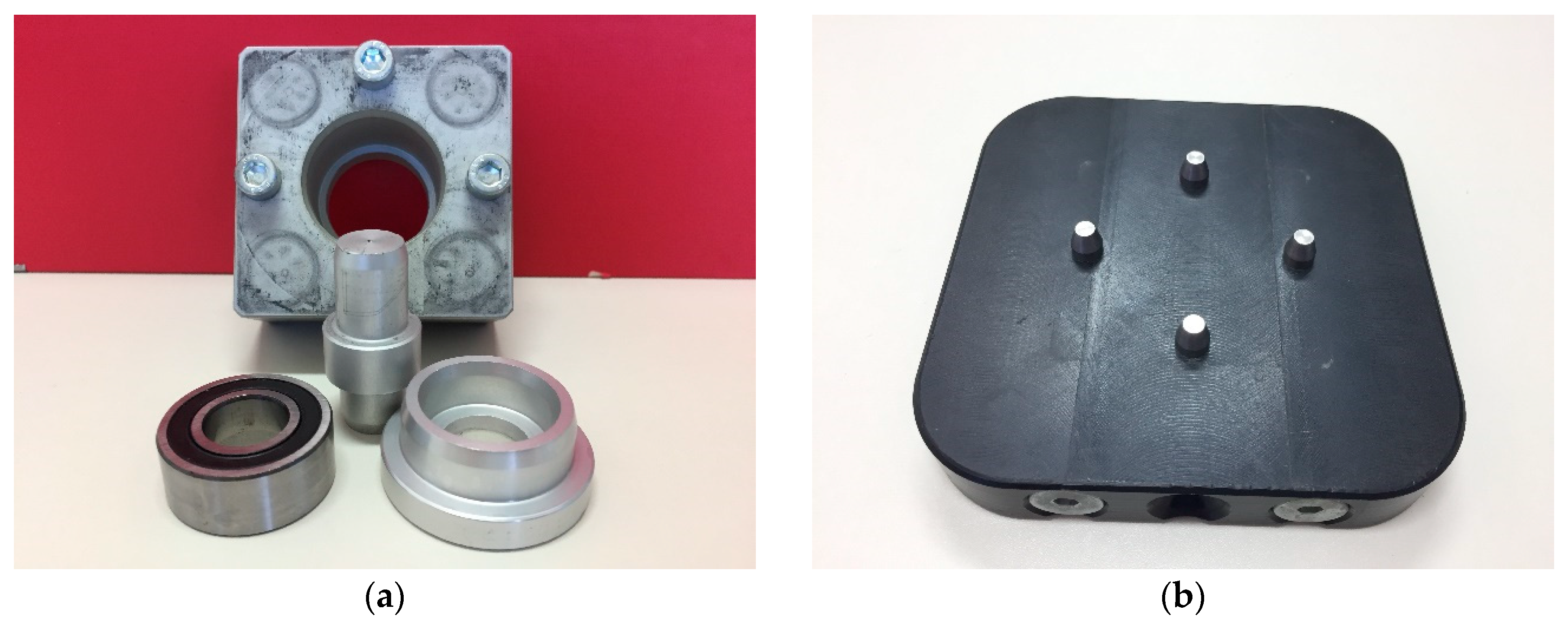
Before addressing the description of the proposed approach to communicate the S&A network and the SCADA application, it is necessary to include, as a starting point, a general description of the FMS of the company SMC (Tokyo, Japan) [
28]. The automated flexible manufacturing cell performs assembly and storage of a turning mechanism. To perform these tasks, the complete system consists of eight stations using components from different technologies (pneumatics, electrical engineering, robotics, etc.). The turning mechanism assembled in the different stations of the cell consists of the following elements: Body, Bearing, Shaft, Cap, and Screws. These constituents are shown in
Figure 1a, whereas the pallet where the set is transported appears in
Figure 1b.
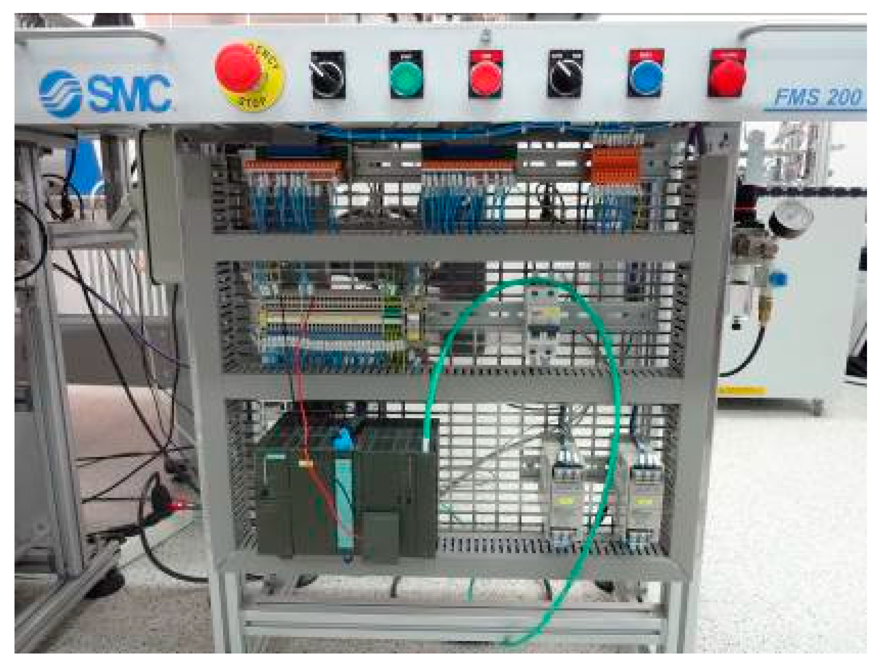
Each of the stations is constituted by a table-like structure on which the different components of each process are arranged, such as robots, pneumatic cylinders, pneumatic distributors, motors, and sensors. On the front of each station, the electrical and electronic components that carry out the control of the station are arranged: switched voltage sources of 24 VC, protection elements, drivers for servomotors, PLC, etc., along with the buttons and indicators used for the manual operation of the station.
Figure 2 shows the front panel and keypads of one of the stations.
The research group has three of the eight stations that make up the entire cell available, namely, station 1, station 7, and station 8, as well as an empty station, which is currently being equipped. The tasks of each station are now explained:
Station 1 (FMS-201): Body supply. This station performs the processes of feeding the body, which serves as a support to the turning mechanism, and the verification of its correct position. This element is fed from a vertical container and can be found in two different positions. If the orientation of the body is correct, it is moved to the transport pallet located in the transfer system. If the base/body orientation is incorrect, the body is rejected (see
Figure 3). The sensors involved in this station are: an inductive sensor to detect the presence of the base, a magnetic (Reed type) detector in-built in a pneumatic cylinder to detect the correct position of the base, and a vacuum pressure switch to guarantee the correct functioning of the vacuum pad. This station also consists of six pneumatic linear actuators.
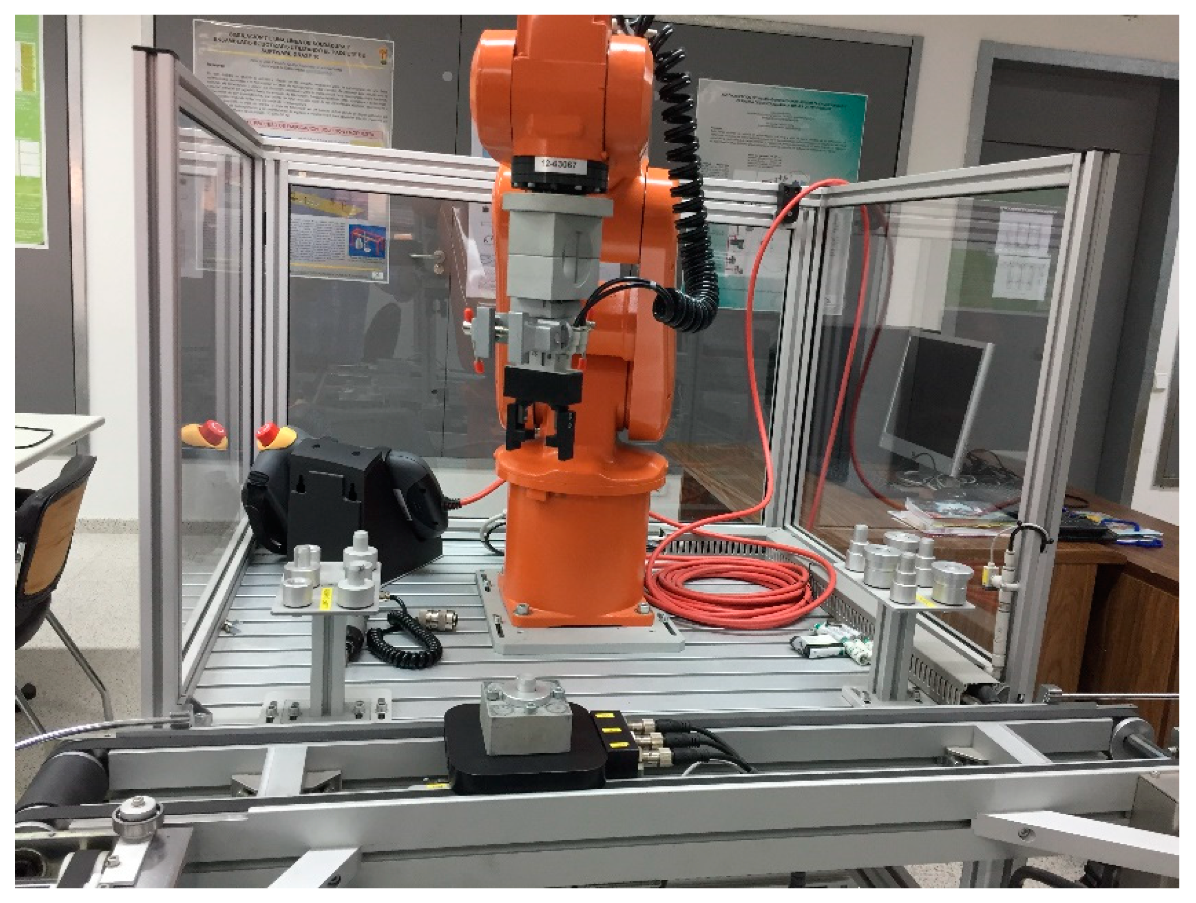
Station 7 (FMS-207): Robotized screwing. In this station, a widely diffused technology is used, such as robotics. This station consists of an ABB multipurpose industrial robot that weighs only 25 kg and can support a payload of 3 kg with a range of 580 mm and six degrees of freedom (see
Figure 4). It should be noted that this station has two programing tasks:
- ∘
Programming of robotic arm movements, contained in the ABB IRC5 controller.
- ∘
Programming of the PLC that controls the work cycle of the station. The PLC commands the IRC5 controller to initiate the sequence that has been programmed for the robotic arm. The IR5 controller returns an end-of-cycle signal when all its instructions have been completed. It also provides information about the execution of the different phases of the cycle (screwing, changing the cover, etc.).
The robotized station is in charge of the adjustment of the four screws placed in the body of the turning device. Nevertheless, due to the fact that the research group does not own all the stations that compound the whole cell, the robot will carry out operations of assembly and disassembly of shafts and covers. Two different operating cycles have been programmed in the robot, whose execution depends on the coding of the transport pallet that supports the set. The so-called short cycle (code: 000) only implies that the cover is changed and the screwing is done. On the contrary, in the long cycle (code: 101), the cover and the shaft are changed and the screwing is conducted.
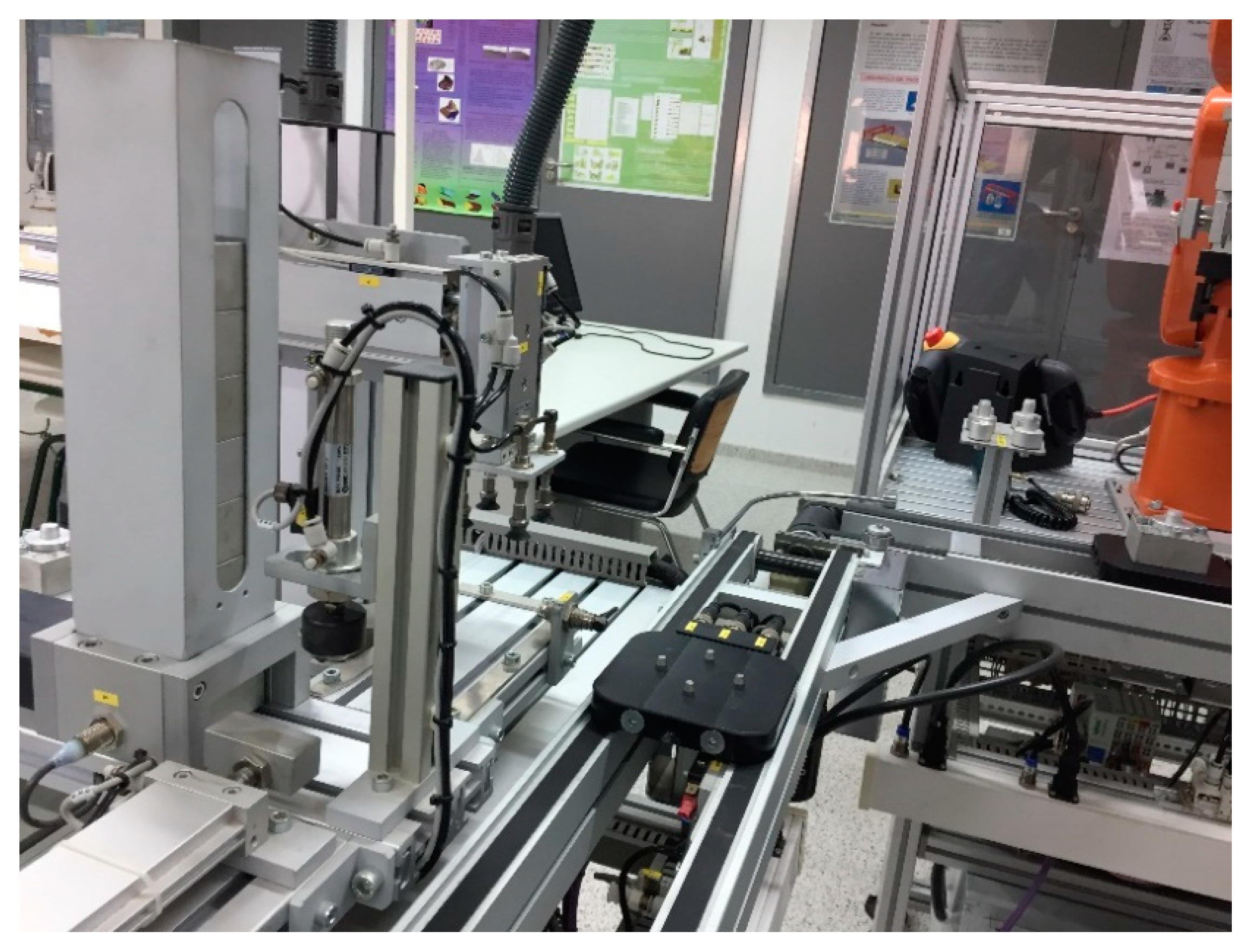
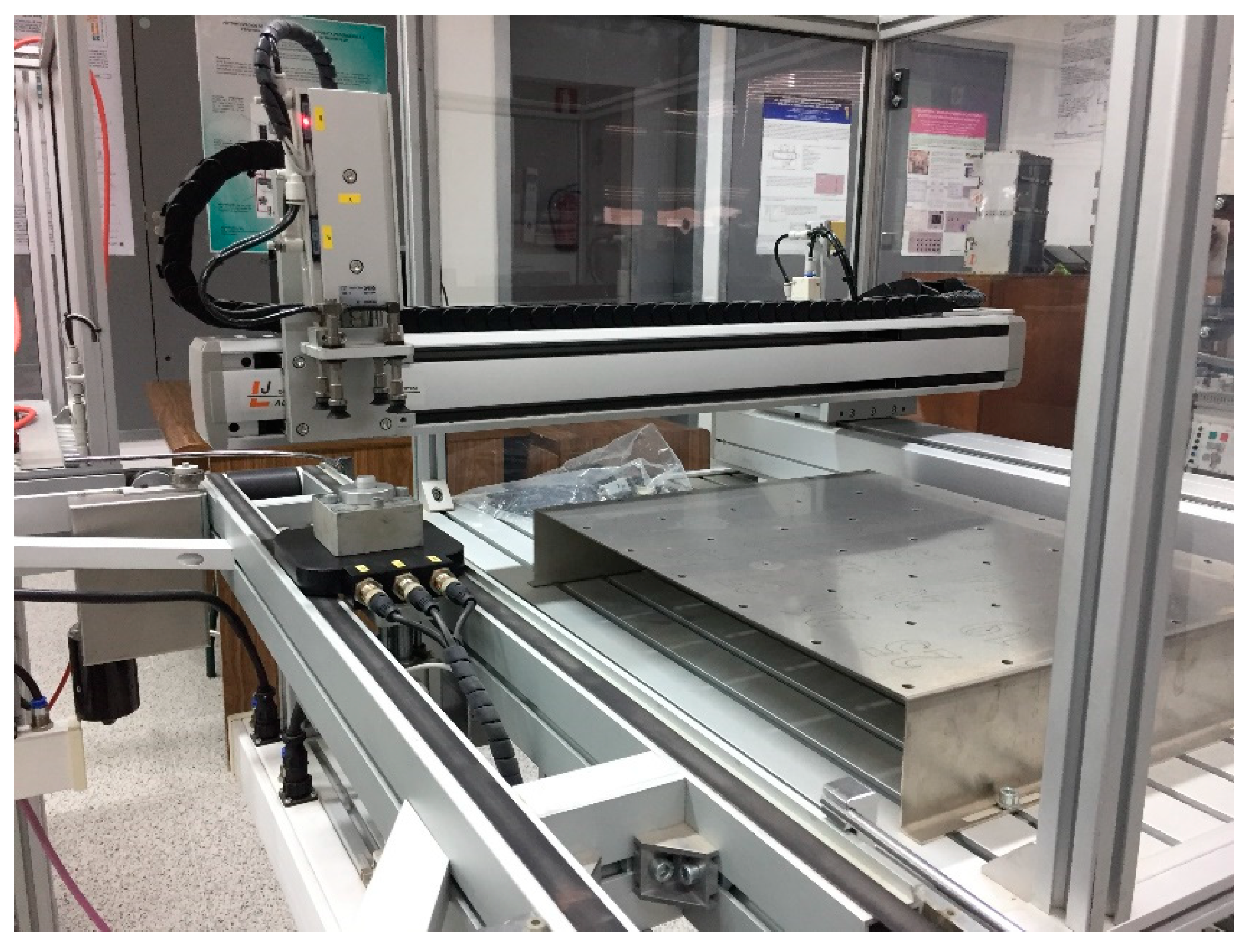
Station 8 (FMS-208): Automatic warehouse. This station corresponds to an automated warehouse in the
X-
Y plane of finished parts. The storage of completed sets in a specific coordinate is done by means of two Mitsubishi servomotors that make up a Cartesian XY system (
Figure 5). The collection and deposit of the completed set both in the transfer and in its corresponding position in the warehouse are solved through a vertical pneumatic axis (
Z axis) equipped with a vacuum pad.
Empty station: This one is intended as a reserve station for future extensions. Its objective is to close the modular transport system (transfer), so that the transport pallet can return from station 8 to station 1, and thus be able to carry out a cyclic and continuous execution of the assembly process.
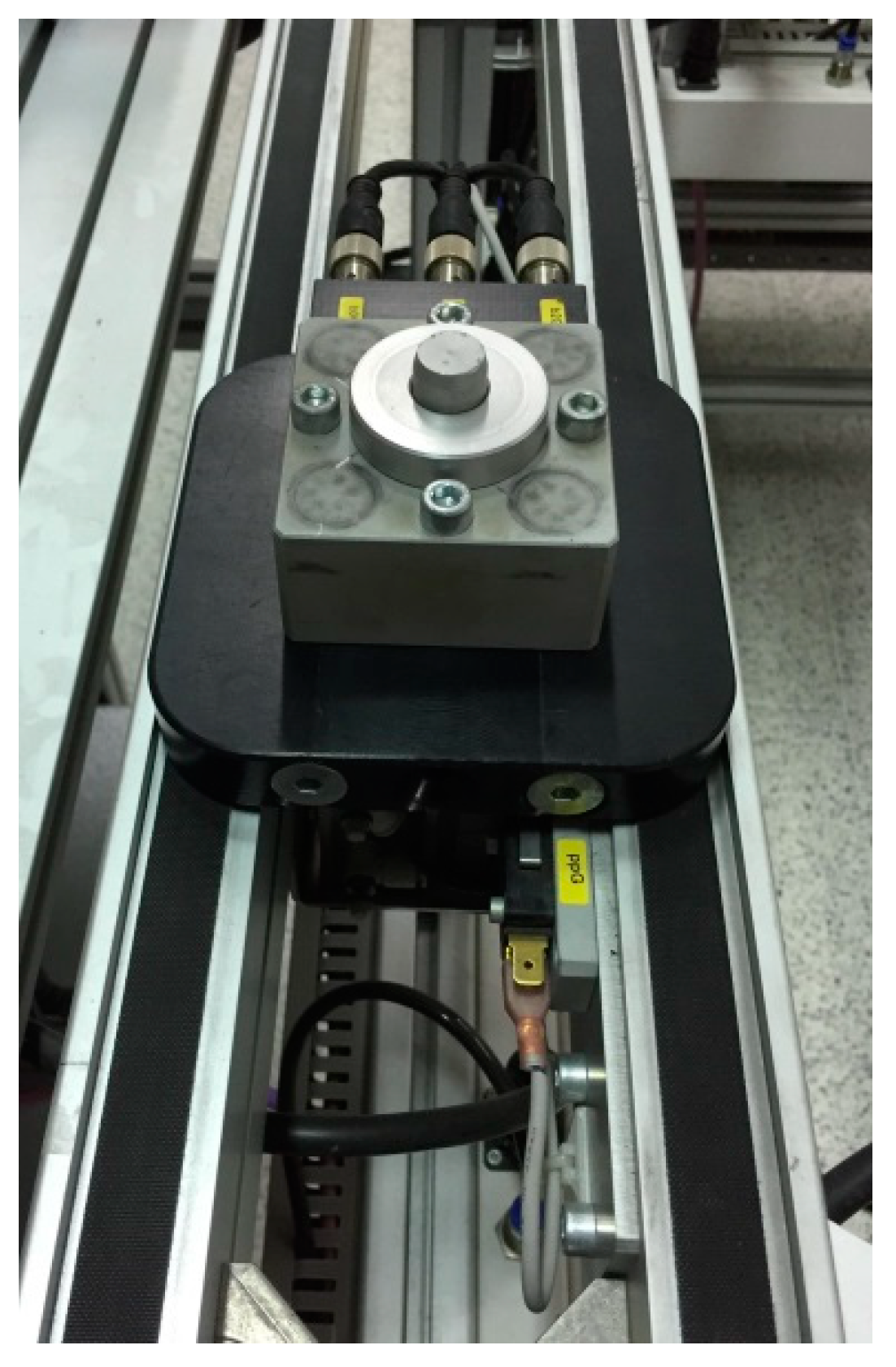
Modular Transfer: All the stations are interconnected by means of a transfer system, consisting of conveyor belts through which the set of pieces moves from one station to another. Consequently, the transport system makes the automatic performance of the process possible. Each of the stations includes an individual transfer section. In this way, multiple combinations of layouts can be developed, with the possibility of joining stations at 90° or 180°. Each individual transfer section includes the retainers and pallet lifters, electrical connections, air vents, and other elements required for its operation. The transfer system incorporates transport pallets in which the pieces are placed so that they can be transported from one station to another, as can be seen in
Figure 6, where the aspect of the final piece mounted is appreciated.
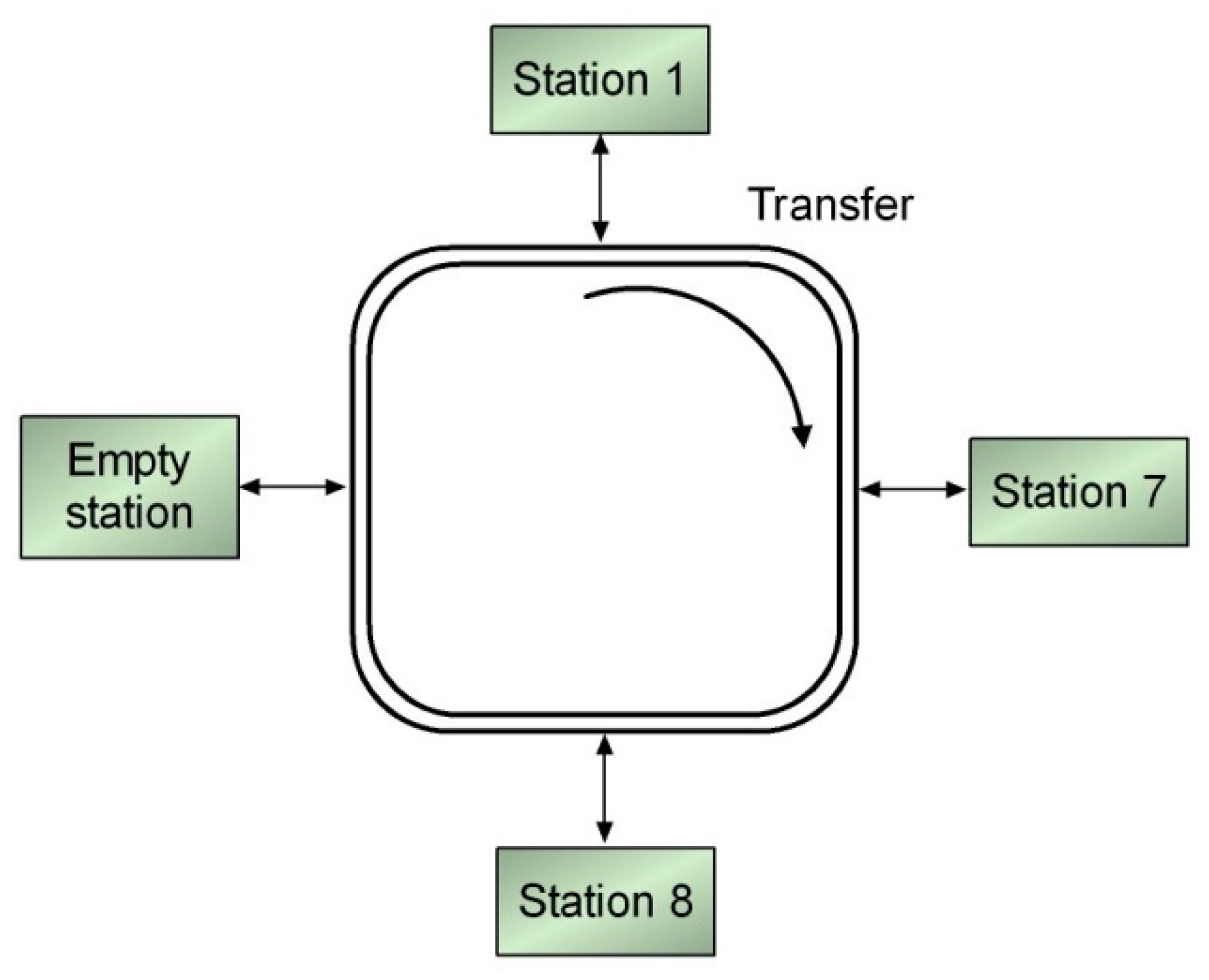
Finally, for a better illustration of the FMS,
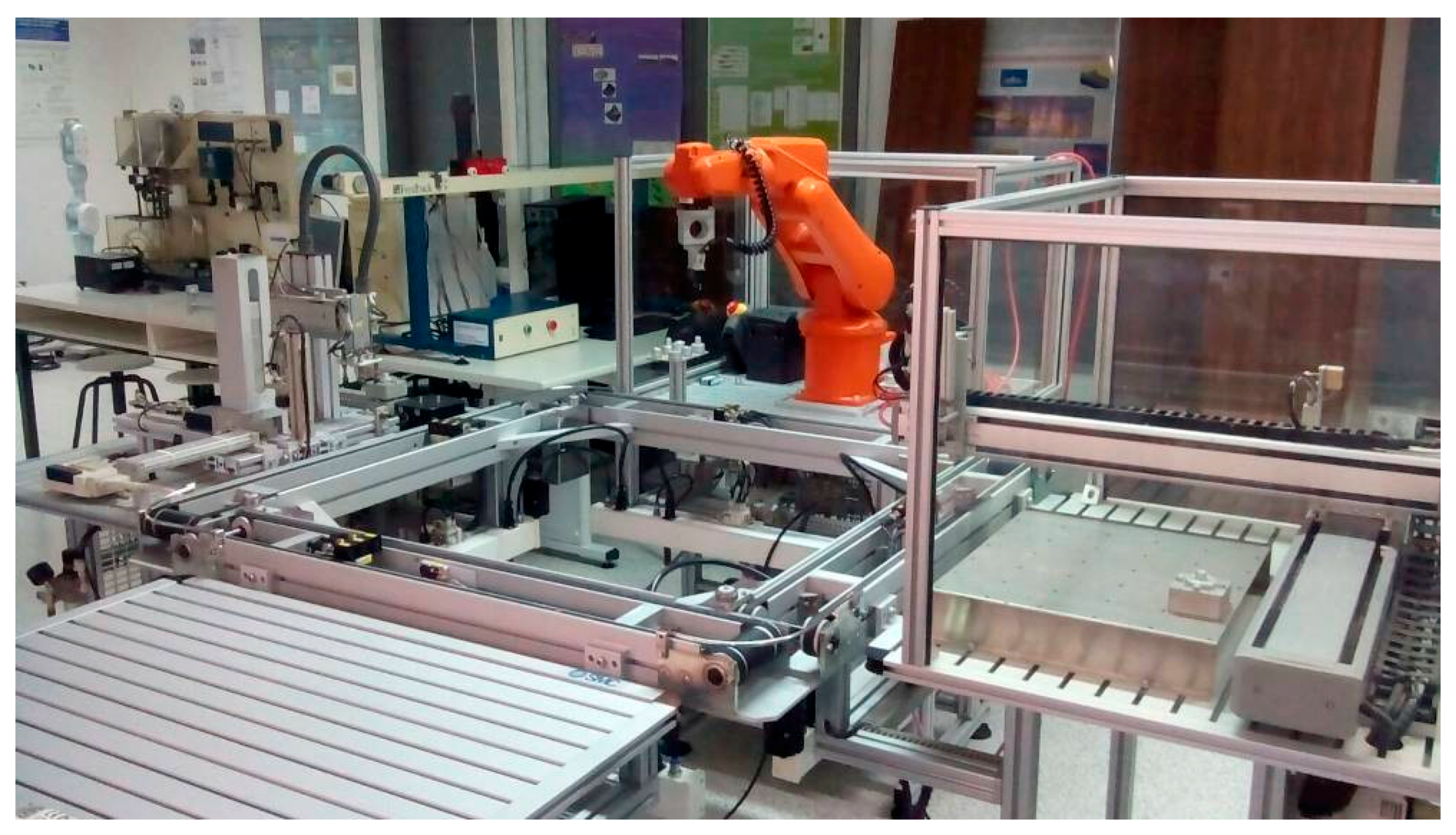
Figure 7 depicts its layout through a block diagram, whereas
Figure 8 shows a snapshot of the current four stations in the laboratory.
3. Proposed System
The problem to tackle is the enhancement of the connectivity of the FMS automation system. The existent PLC support communication through the fieldbus PROFIBUS and the proprietary protocol MPI. These protocols are well-proved reliable and robust in industrial environments, but they lack the possibility of being directly connected to Ethernet networks. The Ethernet connectivity is a paramount requirement for I4.0, as discussed in the Introduction. Therefore, it was necessary to add such connectivity to start the migration process of the legacy system. The proposed solution to share data between the S&A network and the SCADA system is reported in this section. To begin with, it is necessary to describe the automation and supervision system that performs the operation of the FMS. After that, in
Section 3.2, the abovementioned solution to integrate both systems is fully developed. To provide a whole perspective,
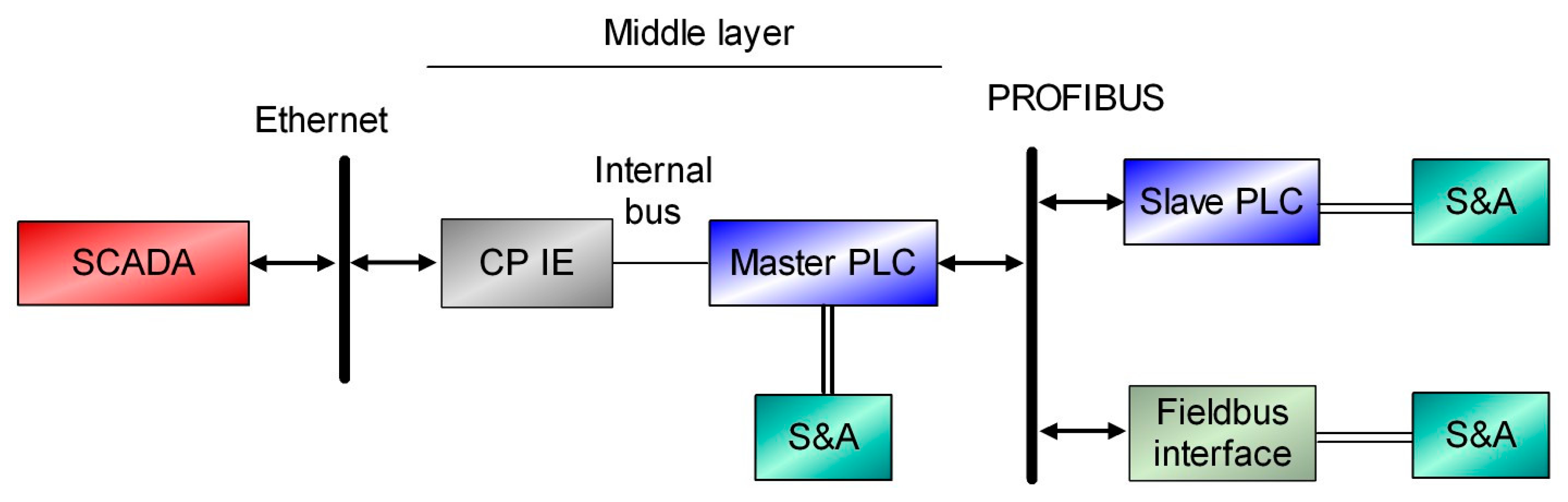
Figure 9 depicts the block diagram of the proposal.
From the point of view of the system operation, there are two network levels in the proposed system, namely: PROFIBUS and Industrial Ethernet (IE). Fieldbus PROFIBUS serves as a communication network among PLC (master and slave units) and distributed Input/Output (I/O) modules. Each of the aforementioned devices includes a communication port for this fieldbus, so, the physical layer of this configuration is already resolved. In this way, the master PLC has access to all the S&A of the manufacturing cell. The communication between the master PLC and the SCADA system is carried out by the standard communication network Ethernet. To this goal, a middle layer that acts as a bridge to link the fieldbus with the SCADA system enables the communication between the master PLC and the SCADA system. Such a middle layer is composed of a Communication Processor (CP) and a software-defined structure to store operational information. Data of S&A are available in the fieldbus through PLC or dedicated interfaces. There are also S&A linked directly to the PLC of station 1.
3.1. Automation and Supervision System
The automation system is implemented by means of hardware and software subsystems, described below.
3.1.1. Hardware Subsystem
In this subsection, all the hardware elements that make up the entire cell will be exposed. The FMS, in its current configuration, is formed by the following elements:
Four PLC Siemens S7-313C-2DP.
One Ethernet CP Siemens CP 343-1.
Two I/O modules Mitsubishi X8Y4.
Two I/O modules Wago 750-343.
One Industrial Robot Controller ABB IRC5.
Two servomotors Mitsubishi MR-J2S-10 CL.
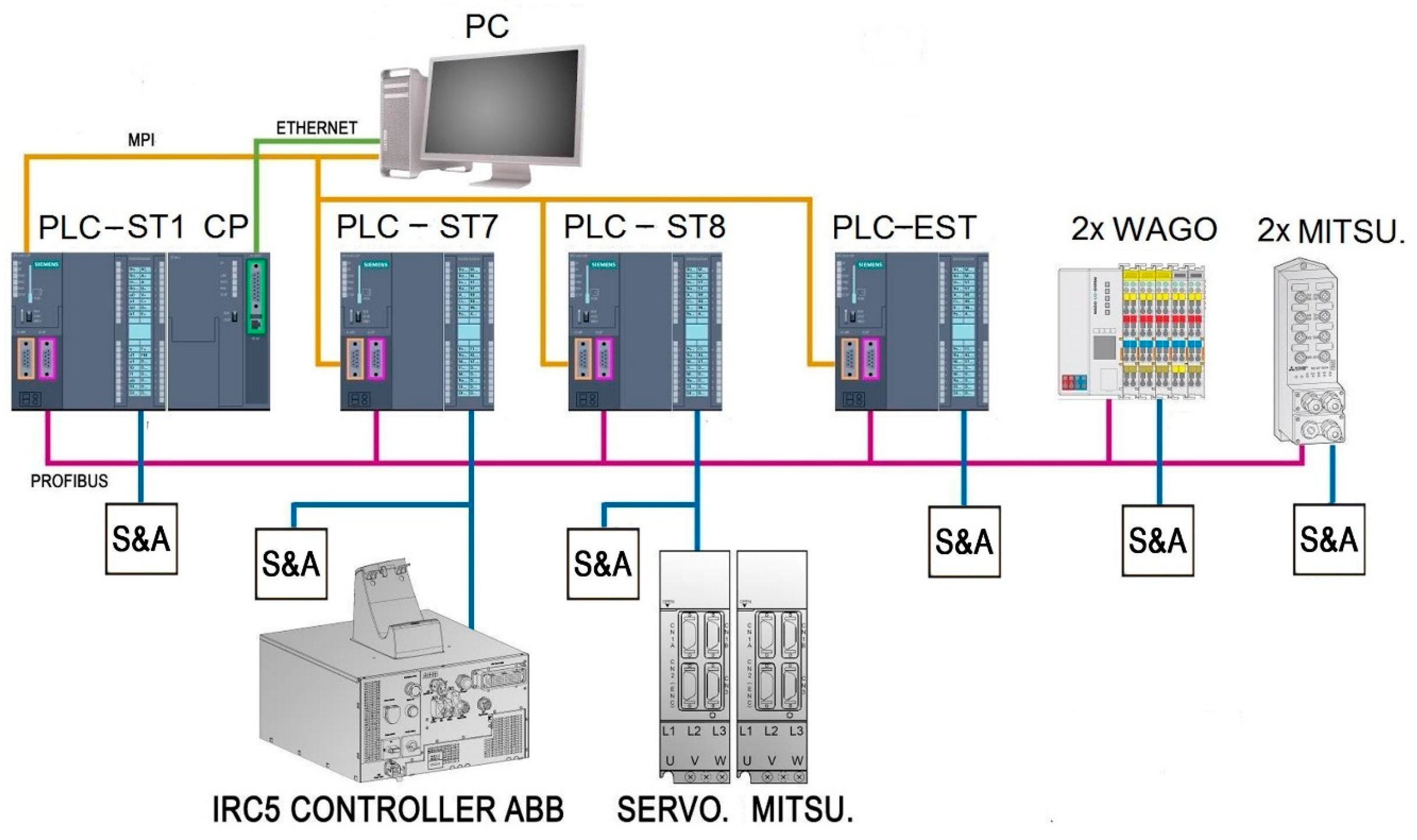
Figure 10 shows the connection diagram of the hardware elements that make up the automation and supervision system of the FMS.
In the top of the automation and supervision system, a Master Terminal Unit (MTU) consisting of a PC-based SCADA system communicates with the PLC of station 1 (PLC-ST1 in
Figure 10). This PLC plays the role of master PLC of the fieldbus PROFIBUS. So, the remaining PLC in the network (PLC-ST7, PLC-ST8, and PLC-EST in the same figure) act as slaves. To this aim, an Ethernet communication module, CP 343-1, is directly coupled to such master PLC through its internal bus. Details about the MTU-PLC communication are developed in
Section 3.2.
The master PLC communicates with the rest of the components via PROFIBUS. These components are configured as slaves and correspond to the Mitsubishi and Wago distributed I/O modules and the remaining PLC. Eventually, for the initial programming and configuration tasks, the PC could also be connected to the PLC through an MPI connection, as indicated in
Figure 9 in an orange color.
The PLC used for the automation of each station is located on the electrical panel mounted on a standardized Deutsches Institut für Normung (DIN) rail. The PLC incorporates 16 digital I/O, both working and load memory, PROFIBUS and MPI interface, and integrated counters and timers. Each slave PLC executes control tasks over the corresponding station and exchanges data with the others via PROFIBUS. In addition, it must be noted that each PLC acts as an interface to link the S&A with the fieldbus. In the case of station 1, S&A are connected directly to the master PLC.
The control of the modular transfer of stations 1 and 8 is carried out with the Mitsubishi distributed I/O modules. These modules, located below their corresponding station, are connected to the fieldbus and have eight inputs and four digital outputs for each one. In the same way, the Wago modules control the modular transfer segments of stations 7 and empty, also linked via PROFIBUS.
Regarding the robots, the control of the movements of the ABB IRB 120 robot is carried out by ABB’s compact controller IRC5. Such a controller is connected to the digital I/O module of the station 7 PLC. On the other hand, the Cartesian robot of station 8 is controlled by two Mitsubishi servomotors, which are connected to the digital I/O module of the associated PLC.
3.1.2. Software Subsystem
The software platform used for the development of this project is Totally Integrated Automation Portal V13 SP1, which has been recently referred to as the foundation of digital factories [
20]. The programming of the automation system has been carried out with the STEP 7 Professional package, an engineering software for programming and configuring Siemens controllers included in the TIA Portal platform. The programming of the supervisory system has been resolved with the WinCC package from Siemens (Munich, Germany), also included in the TIA Portal platform.
To carry out the programming of the automation system, three modes of operation of the FMS have been considered, namely:
Maintenance: Allows the operator to access each input and force each output that makes up each of the stations and the transfer system. In this way, it is possible to know if any component (actuator or sensor) is faulty.
Monitoring: Corresponds to the normal automatic operation of the FMS. In this state, the defined work cycle for each of the stations is executed.
Stand-by: The stations remain in stand-by state until either of the two previous states has been selected. In addition, the stations are placed in their initial conditions.
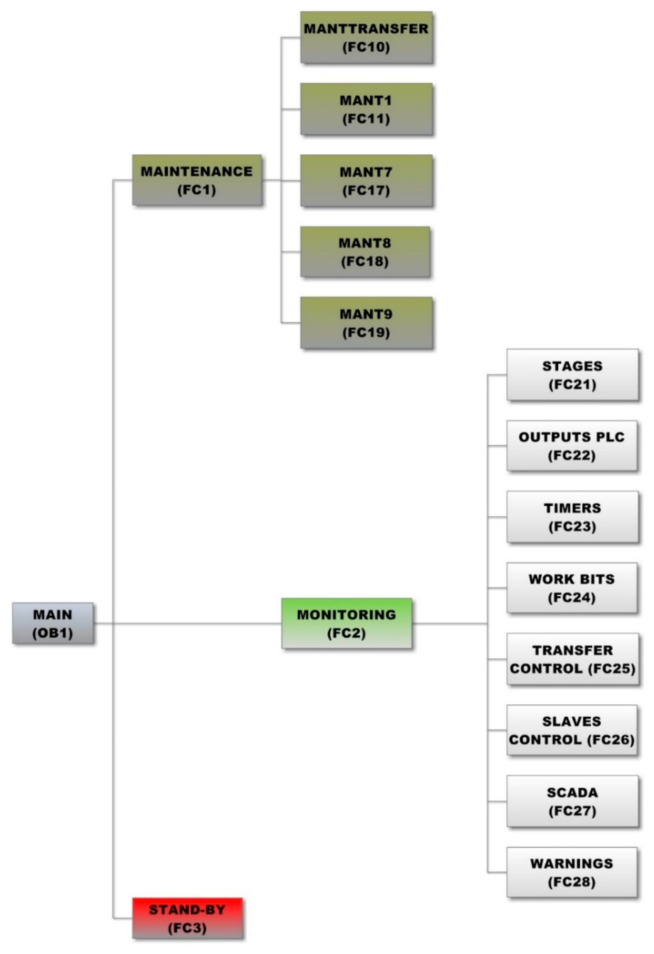
The user program of each of the PLC that make up the automation system is structured in a series of blocks, called Functions (FC). The following diagram shows a flow chart that portrays the structure of the master PLC program (
Figure 11).
From the Maintenance FC (FC1) calls to the MantTransfer, Mant1, Mant7, Mant8, and Mant9 functions are made. These FC correspond to the maintenance tasks of the transfer and the four stations, respectively. They are contained in the program of station 1. As aforementioned, this is the station which the SCADA system accesses to show the activation and deactivation status of the S&A of both the transfer system and the four stations.
The automatic operation mode of the FMS is programmed in the Monitoring FC (FC2). This mode is similar in the four stations, although the PLC program of station 1 (PROFIBUS master) includes some additional functions to control the other bus devices. This FC contains the following secondary FC:
Stages: Conditions that mark the steps or stages that make up the processes of each station.
PLC Outputs: Conditions that control the state of the actuators.
Timers: Contains all timers that are used in programming.
Work Bits: Conditions for the status of different important marks of each station, such as: initial conditions, cycle running, and base accepted, etc.
Transfer Control: Conditions concerning the operation of the transfer.
Slave control: Conditions concerning the operation of the slaves corresponding to stations 7, 8, and 9.
SCADA: Where the variables related to the SCADA system are updated.
Warnings: Contains the conditions that activate and deactivate the warnings defined by the developer (it only exists in the master PLC).
3.2. Integration S&A Network-Ethernet-SCADA
A middle layer composed of a CP and a software-defined structure to store operational data has been developed. On the one hand, the hardware linkage is implemented by a CP module that enables the integration of the master PLC in an Ethernet-based network. On the other hand, an array of Data Blocks (DB) in the master PLC makes the sharing of information between the SCADA and the S&A network independently of their location possible.
As previously commented upon, the CP module is responsible for establishing such a connection, both for the programming of the first station PLC and for communication with the SCADA system. The CP includes a RJ45 port to accommodate an Ethernet wire. Another capability is a customizable web page hosted by this module that allows web-enabled diagnostics via Hypertext Transfer Protocol (HTTP) clients. It should be noted that in the present work, this capability has not been exploited.
Concerning the software level, DB are memory positions of the PLC where measurements and signals are stored. These blocks can be of two types, global or instance DB. The access to the latter one is restricted to a particular Function Block (FB). The first type has been the selected one in order to have access to the hosted information by any part of the PLC program. Taking advantage of the Ethernet connectivity afforded by the CP, the data shared through the fieldbus and the DB-based storage, a seamless integration between the SCADA system and the S&A network has been developed and implemented.
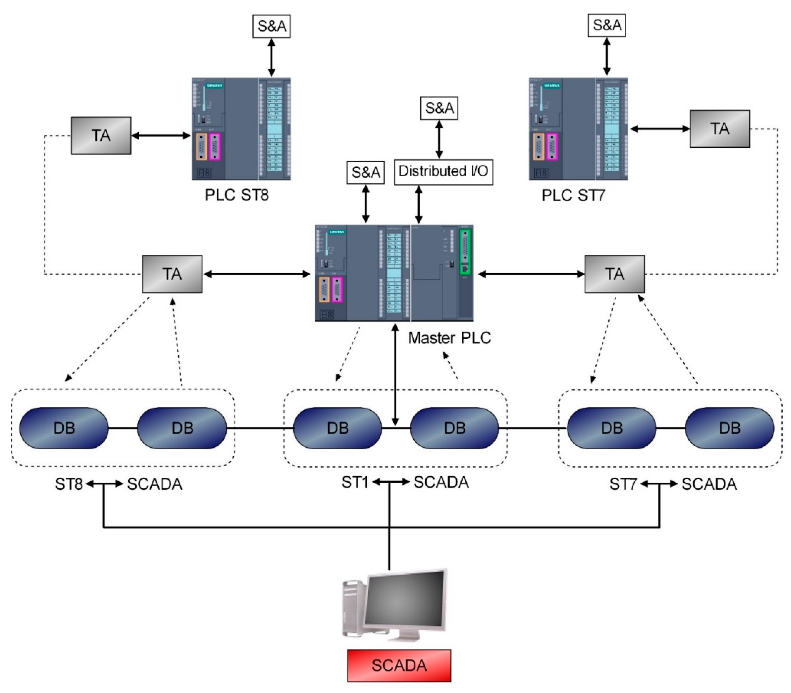
To allow access to the data of all the stations and S&A, a software structure based on DB has been created in the master PLC of station 1 (
Figure 12).
When parameterizing the PROFIBUS communication, a Transfer Area (TA) is defined to act as a buffer of the shared information. In the presented approach, two TA for each PLC have been defined: one for input data and the other for output data. As a consequence, two DB have been created for each PLC, where one DB is devoted to Read values and the other one hosts Write values. Read values are the signals from S&A, which constitute information to be read by the SCADA system. On the other hand, Write values correspond to command signals that the operator/user introduces through the supervisory interface. The empty station nowadays does not require any DB because there is no information to be shared. Hence, a total number of 6 DB are used, as can be observed in this figure. This division of information facilitates modifications or maintenance tasks, both for current legacy equipment or future new devices.
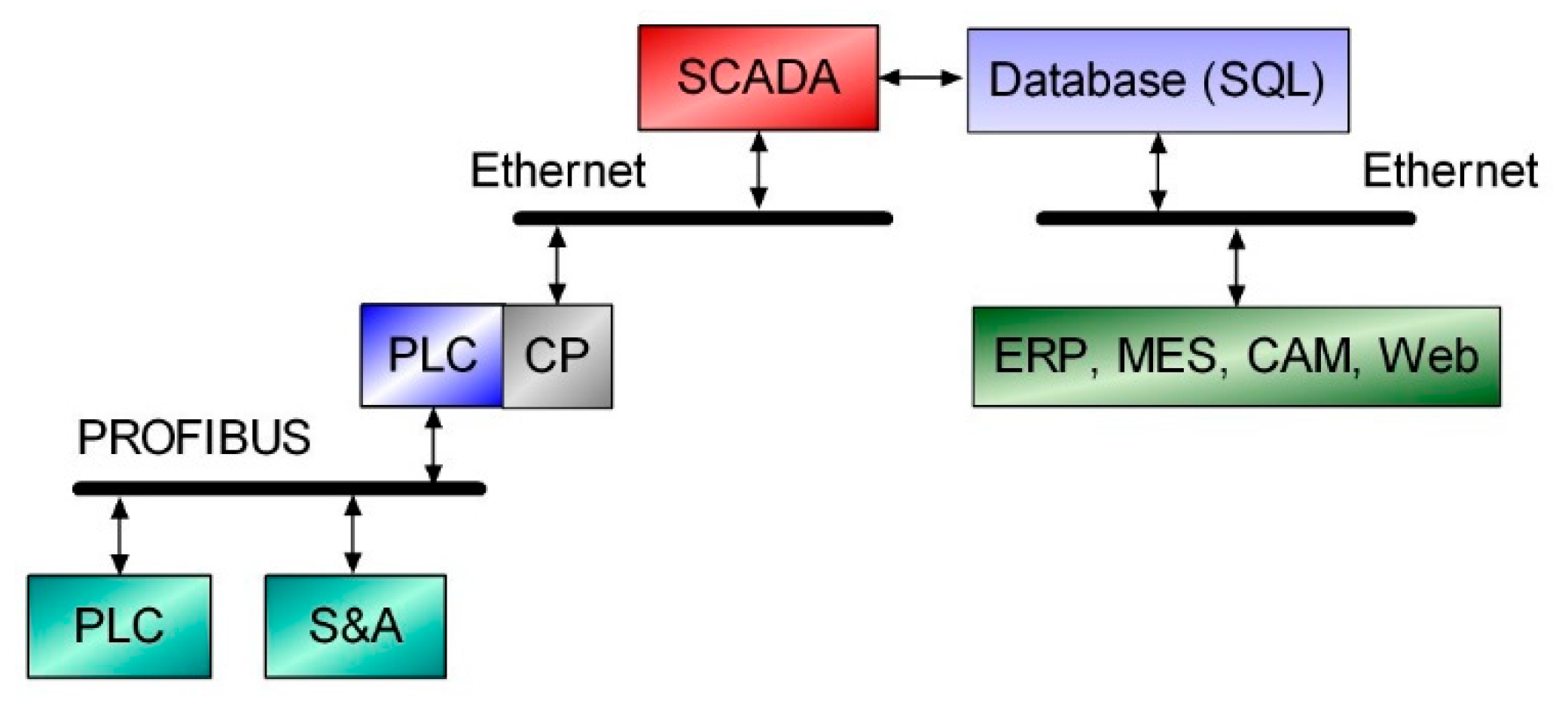
In this way, the master unit gathers all the information of the FMS and makes it available for the SCADA. In other words, the information related to all S&A and internal parameters of PLC are “concentrated” in two DB for each station and can be shared with higher-level applications. Therefore, this information is available not only for supervisory interfaces, but also for other software applications devoted to the control of production, Enterprise Resource Planning (ERP), Manufacturing Execution Systems (MES), Computer-Aided Manufacturing (CAM), and so forth.
Figure 12 depicts the information flows regardless of the physical medium where it occurs. A continuous data flow takes place between the different elements. For instance, signals from S&A of the transfer are interfaced with PROFIBUS via the distributed I/O modules, and exchanged with the master PLC through PROFIBUS. Once these stages are completed, the supervisory program accesses the signals by means of the Ethernet channel.
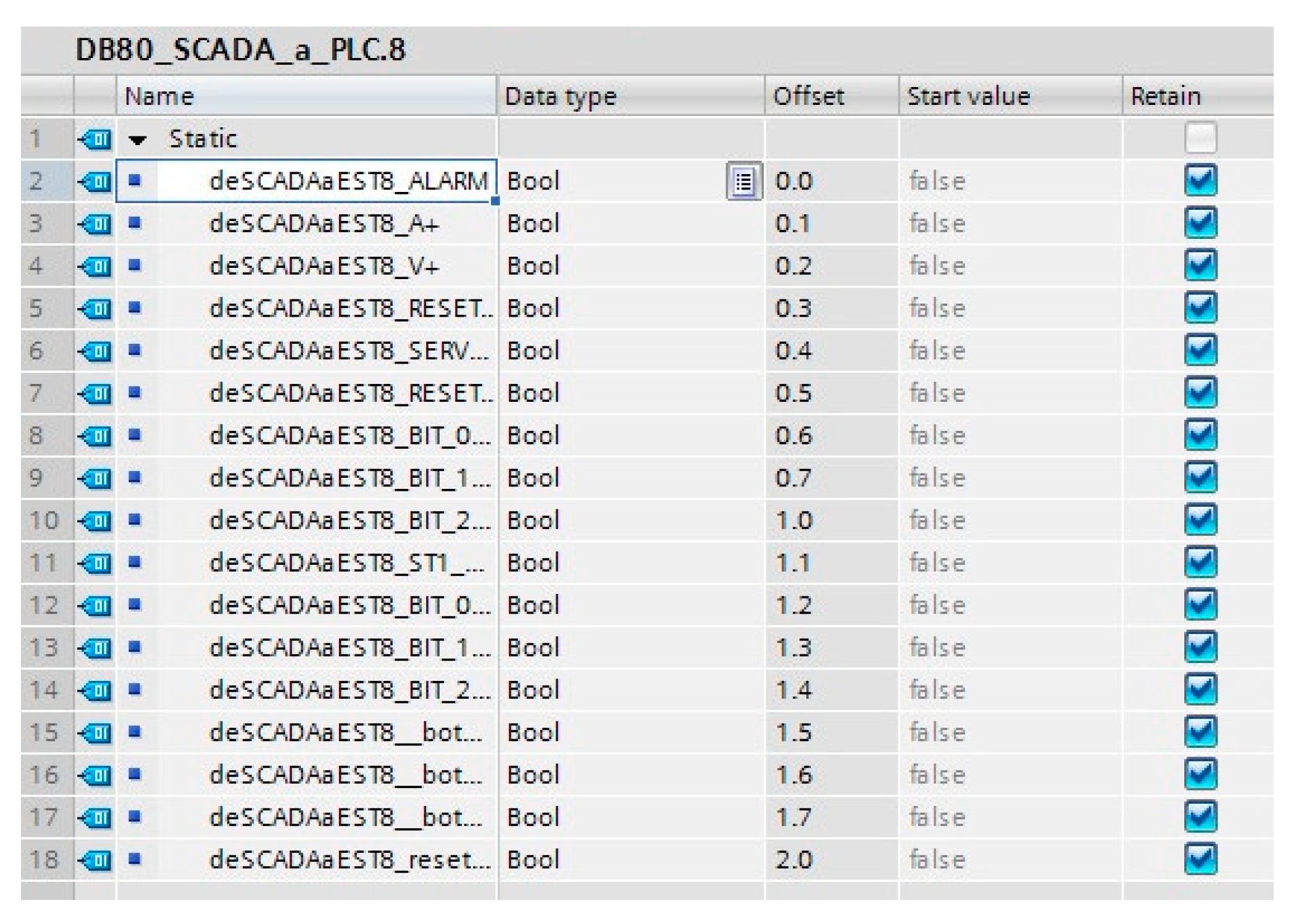
As a sample of this scheme,
Figure 13 shows the aspect of the DB designed to exchange Write values between the SCADA system and the PLC of station 8, named DB80, with the master PLC acting as the intermediate layer.
Concerning the parameterization of the Ethernet-based communication, the master PLC and the MTU are connected in a Local Area Network (LAN). The configuration of this communication requires defining the IP address in both nodes. Despite the fact that the supervisory application is presented in the next section, it has been considered more convenient to expose here such a configuration for a better exposition of the developed solution.
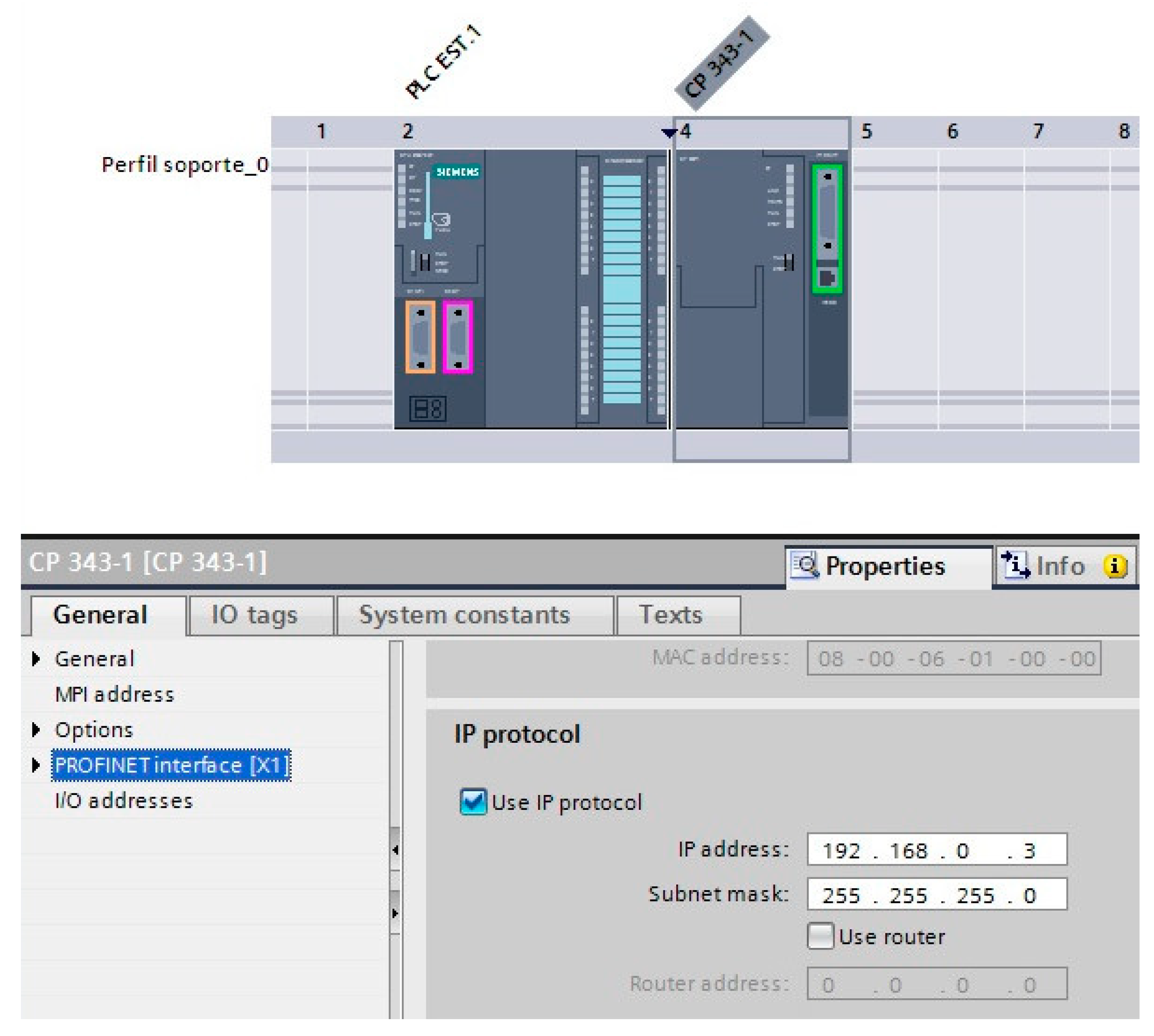
The assignment of the IP addresses is made using the TIA Portal suite. Particularly, the IP address of the CP is defined in the Device configuration menu (
Figure 14). The subnet mask must also be specified. Within this menu, the properties of the CP include the parameterization of the PROFINET interface, where the assignment of the IP address is performed. In this regard, it should be noted that this interface allows the use of fieldbus PROFINET or Industrial Ethernet. In the present case, the latter one has been applied as aforementioned. Other configurable features are related to the MPI network, but this connectivity has not been exploited for this application.
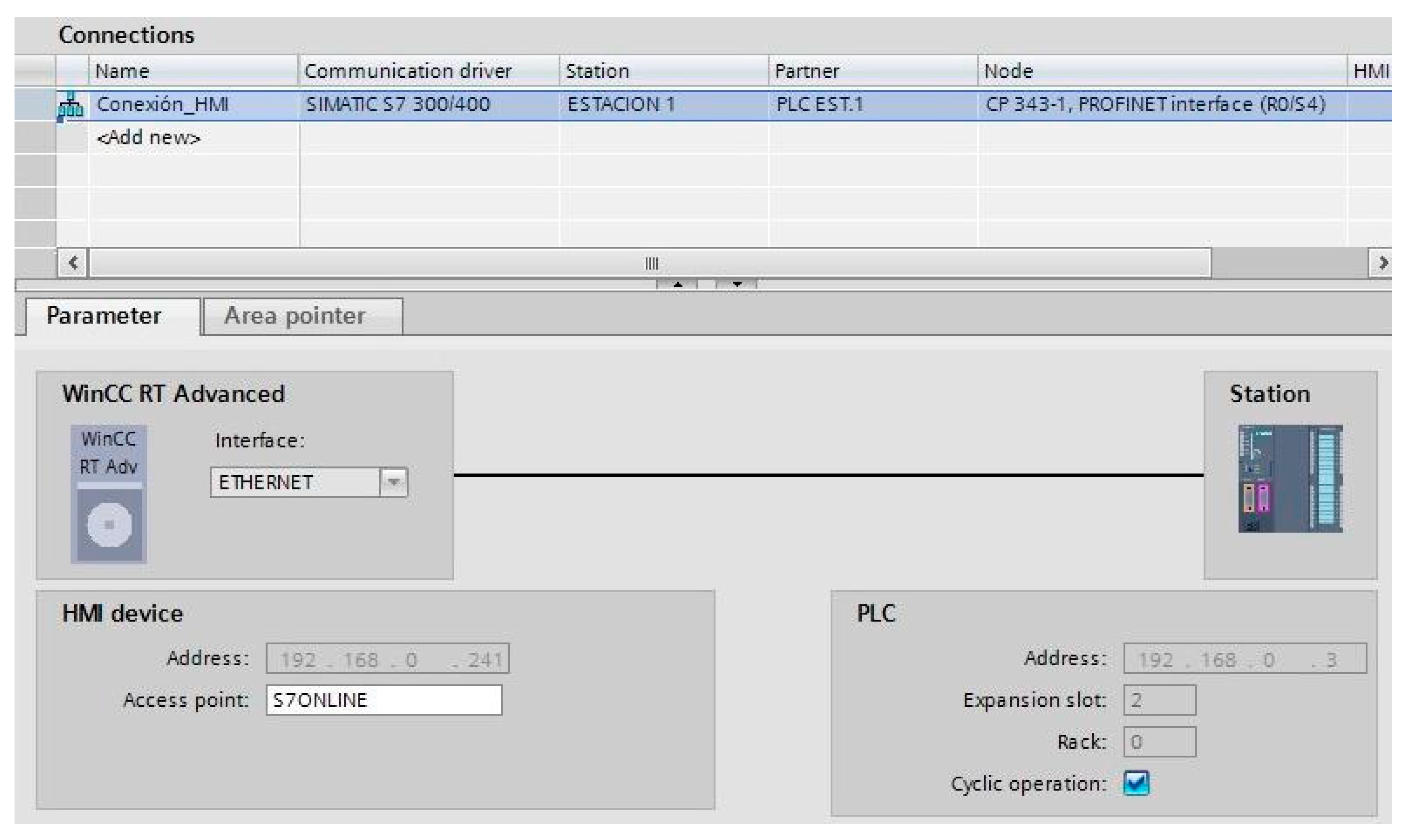
Regarding the MTU, the employed Ethernet interface is a common Peripheral Component Interconnect (PCI) Ethernet card. In WinCC, its IP address in established in an equivalent procedure to that followed for the CP. In addition, for a proper communication MTU–PLC, it is necessary to parameterize a connection within the WinCC, as shown in
Figure 15. As can be seen, the addresses of both devices belong to the same range within the LAN.
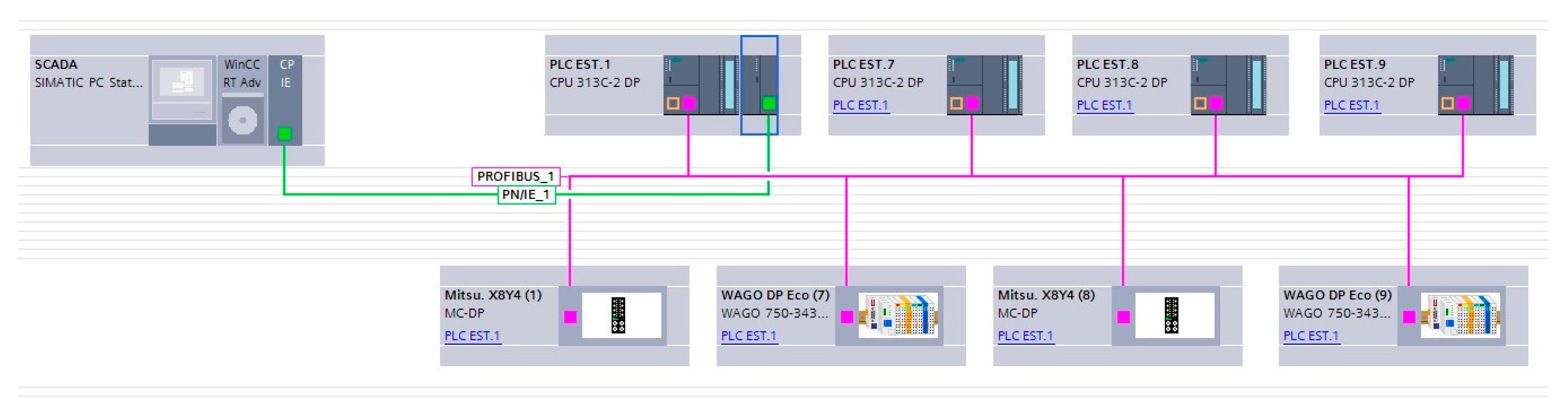
As a result, the Network View of TIA Portal depicts the configured network, including both the PROFIBUS segment and the Ethernet link (
Figure 16). One can observe that both networks correspond to those depicted in
Figure 10.
4. Results and Discussion
In this section, the achieved results are expounded and discussed. Once the Ethernet connection and the DB structure have been configured, all the operational information of the S&A network and of PLC is available to be monitored. To this aim, a SCADA system has been developed and deployed, demonstrating the feasibility of the proposed approach. Furthermore, a database has also been generated to afford this information to other software applications.
4.1. SCADA System
As briefly indicated in the Introduction, a SCADA system is a software application specially designed to work on computers in production control, providing communication with field devices (S&A, PLC, etc.) and controlling the process automatically from the screen. It also provides all the information generated in the production process to diverse users, both at the same hierarchical level as other supervisory users within the company (supervision, quality control, production control, data storage, etc.).
The program used for the design and implementation of the SCADA system is WinCC, included in the TIA Portal platform. Using the aforementioned program, the following functions are carried out: browsing through different screens, control of process variables, start-up of the system, user administration, warnings system, collection of process data and transfer to external files (historical data), scheduled tasks, etc.
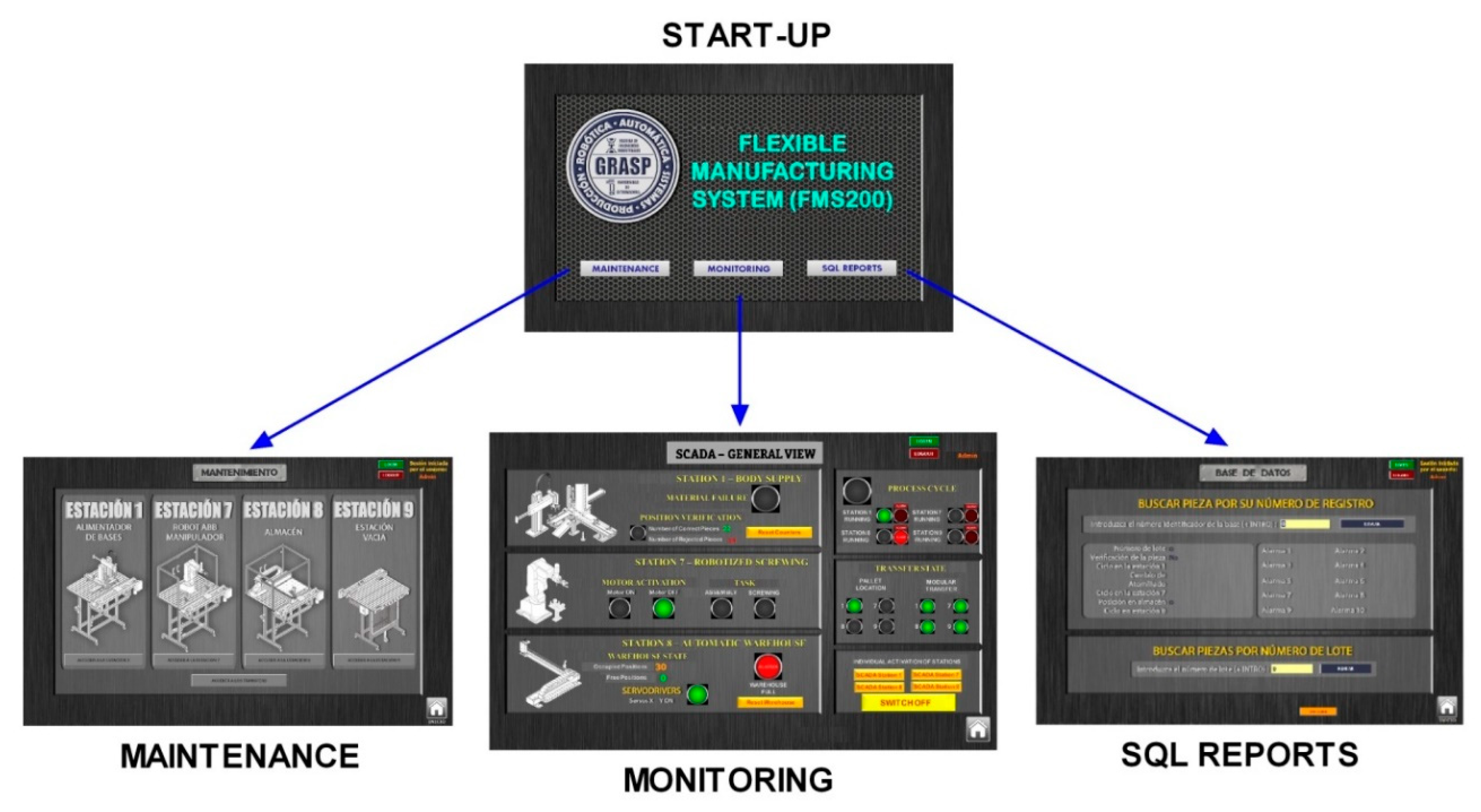
The SCADA system is composed of 14 screens, through which the user can navigate to access all the options and is able to track the process of the FMS. The SCADA system has the following structure:
Maintenance: This option is focused on being able to carry out checks of each one of the S&A of the stations.
Monitoring: This second option makes it possible to carry out the monitoring of the productive process without the need to be in situ next to the stations thanks to the implemented Ethernet link. In this way, it is possible to know at each moment where the platform is located, what sensors are activated, and what action is being taken.
Data storage: This last option permits the access to an external database with the most important parameters of the work processes performed on each piece.
Once the SCADA runtime starts, the home screen containing the user identification by name and password, and access icons to the three operating modes of the system appear, as can be seen in
Figure 17. It should be noted that user administration is a paramount functionality in the exploitation of SCADA systems. With the establishment of access permissions, the protection of important data of the process is guaranteed and the execution of certain functions in runtime is regulated. Users and user groups are created and specific access rights called “authorizations” are assigned to them.
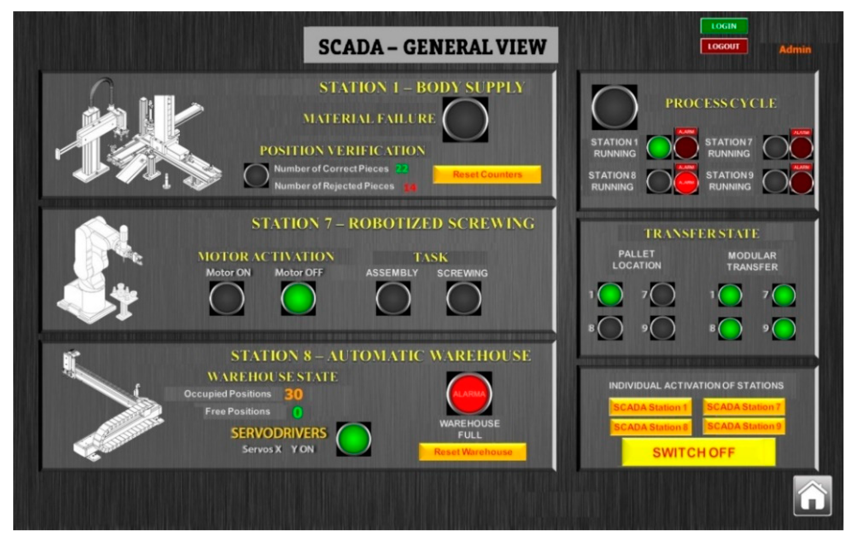
The monitoring-devoted screens are described below. With these screens, the behavior of the FMS working in automatic mode can be supervised. This mode consists of a main view (
Figure 17) in which the basic indicators appear to check the operation of the global system, as well as the buttons for set-up and to reset the counters of correct parts and of the full warehouse batch. Finally, from the main view, it is possible to access the warnings to visualize the operating states and the present faults and alarms in the installation. Obviously, the empty station has not been fully included in this screen since it does not perform operations over the piece, and only allows the cyclic transport of the pallet.
As a proof of concept,
Figure 18 shows the main monitoring screen under real operation of the FMS. As can be seen, the working station is indicated in the top right corner, and in the presented case, station 1 is processing body pieces (see the corresponding green indicator). The pallet is placed in this station, which is shown by a green indicator in the section devoted to the transfer state. Concerning the automatic warehouse, an alarm state is reflected, showing that the warehouse is full. The maximum number of stored pieces (30) has been reached, so it is signaled by means of a red LED indicator in order to inform the operator. This human-requesting situation is solved by resetting the counter (button Reset Warehouse) once the positions have been manually released.
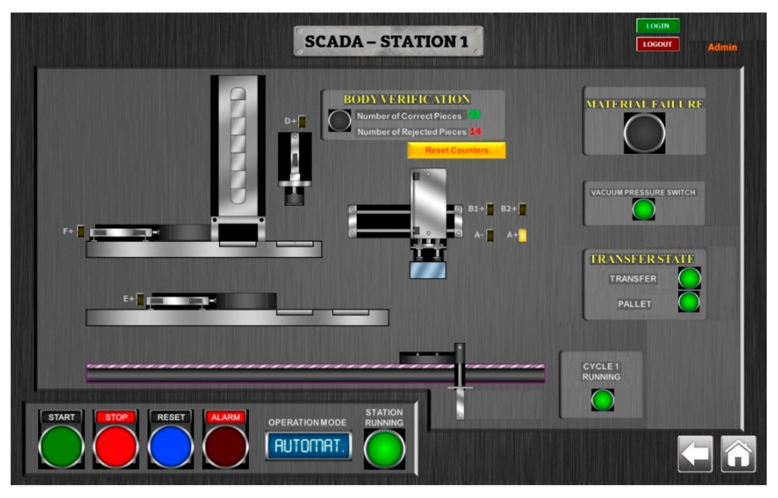
There are also screens to access the monitoring of each station separately. Through animations and Boolean indicators, the evolution of the process can be observed in real time. Other actions that can also be performed are resetting the counters of accepted and rejected parts, restarting the ABB robot system, or resetting the warehouse positions. For instance,
Figure 19 shows the screen dedicated to monitor the first station. The reflected case corresponds to that commented on for the previous screen. This one provides illustrative information about the operation of the S&A of the first station. Namely, the pallet is detected, the correct position of the base is verified, and the vacuum pad works properly to place the base over the pallet.
4.2. Database Report
Concerning data storage, it must be remarked that the continuous recording of data allows its subsequent use and, therefore, also its graphic representation, comparison, creation of statistics, analysis, etc. Consequently, the registration of process data (historical) and its possible exploitation is a basic functionality of the supervisory system. For this purpose, the monitoring systems are linked to databases, usually external to them. In this way, the monitoring systems allow the historical tracking of the product (traceability), the comparison of campaigns, or their use as a virtual test bench for the training of operators without the need of direct connection to the process. The use of external databases allows access both from the monitoring environment and from other applications through standard languages, which results in the most convenient way to integrate industrial computer systems. Structured Query Language (SQL) is one of the most widespread languages and is adopted by most manufacturers and suppliers of industrial software. In this work, the process of archiving information of interest was solved through Visual Basic (VB) scripts that are generated by variable value change events.
To this aim, first, the configuration of the communication between WinCC software and SQL Server is addressed. The access to an SQL database in WinCC Runtime software is done through scripts. To access an SQL database, it must be previously created on the SQL server. WinCC Runtime software acts as an SQL client. A communication using the Open DataBase Connectivity (ODBC) standard with the SCADA application establishes data streaming towards the database. The goal of ODBC is to allow access to any data from any application, no matter what DataBase Management System (DBMS) stores the data.
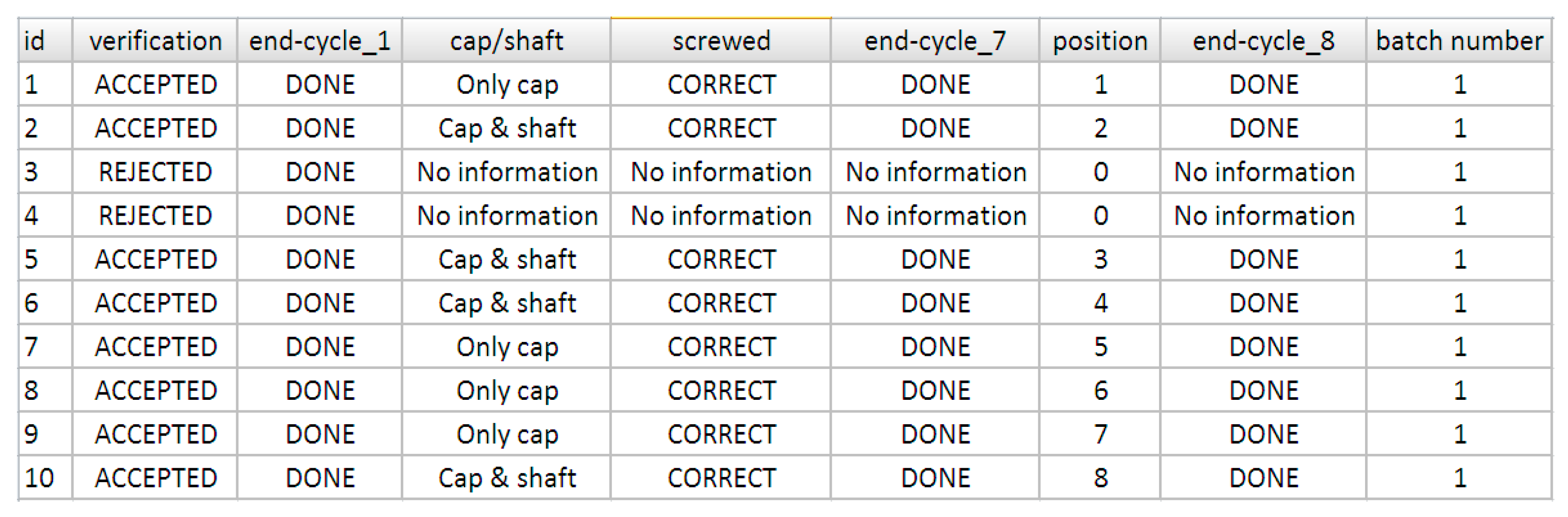
Now, through scripts, the developer can create new registers for each new piece, update the information for the current task of the cycle, or allow the user to search a specific register by entering the identifier in the input field.
Figure 20 shows the result obtained for the database using the aforementioned scripts. In this way, the information of the FMS operation is successfully stored and can also be accessed by other software applications like those devoted to ERP, MES, CAM, or web-based remote visualization.
Figure 21 depicts, in a simplified way, this availability of database-supported information.
4.3. Discussion
In view of the achieved results, the following discussion is conducted. This work constitutes the first step in the migration of a legacy system, namely an FMS, towards the I4.0 concept. As expounded in the previous subsections, the experimental results prove the feasibility of the proposed solution.
The presented development has enabled the integration of an S&A network with a SCADA system. To sum up, the legacy feature of the existing PLC has been overcome by means of an Ethernet link between the supervisory interface and the master PLC. Therefore, all data of the S&A network can be effectively retrieved by such a supervisory interface. The designed SCADA system affords the relevant information with user-friendly and easy-to-use features.
The proposed solution is generalist in the sense of being valid if other SCADA software is used. For instance, the widely known LabVIEW environment could also be used, so particularities of such software should have to be configured but the communication bridge would remain the same. In this sense, the communication between the master PLC and the SCADA application should be conducted through the standard Open Platform Communications (OPC), but the middle layer implemented in this work would be the same. Likely, information storage in databases is a widely supported functionality regardless of the specific supervisory software suite.
As more features of I4.0 are included within the FMS, it will be necessary to manage the heterogeneity of components (software and hardware). This issue will be approached by means of the aforementioned OPC protocol, namely the Unified Architecture (UA) specification, whose advantages are able to address the challenges introduced by the Industry 4.0 [
19].
The implemented scheme is envisioned to facilitate the addition of other S&A that include embedded Ethernet connectivity, especially modern IoT-enabled S&A.
Remote access for online supervision is afforded by the remote connection options of the SCADA system. In the present case, WinCC offers web connections, as well as a Virtual Network Computing (VNC) desktop interface. In the developed system, this function has not been exploited in order to avoid unauthorized intrusions in the network of the university.
The time and effort devoted to implementing the proposed approach has required deep expertise related with automation to configure the PLC, whereas the deployment of the Ethernet link with the SCADA system has not required high level knowledge about networking over Ethernet. The structure of DB also implies a profound skill for managing distributed I/O signals in the PLC and the fieldbus PROFIBUS. It must be taken into account that the usage of industrial fieldbuses imposes detailed parameterization, whereas the Ethernet means does not require low level configurations. This issue is considered as a benefit in order to facilitate the migration towards I4.0.
In an exercise of self-criticism, the presented FMS still has a long way to go until it becomes a fully I4.0-compliant system. In fact, innovative trends can be incorporated like Radio Frequency IDentification (RFID), virtual/augmented reality, Cloud computing, cyber security means, or open source resources.
Regarding that last trend, a drawback was found when designing the SCADA system with the TIA Portal due to the associated license costs. This aspect is important because the available budgets are continuously decreasing. To solve this situation, a research line is focused on developing a supervisory system using open source software. In fact, open source hardware and software projects are key accelerators for the industry adoption of IoT [
29]. In the same regard, the FMS is able to act as a benchmark to research the integration of PLC and open source hardware devices in the context of legacy systems. An example consists of connecting an Arduino microcontroller through an Ethernet shield or an inbuilt port, so a communication channel is established.
Virtualization of manufacturing processes by means of virtual or augmented reality is also a merging movement, envisioned to enhance human-machine interaction in the I4.0 context [
30]. Ethernet connectivity will facilitate the sharing of information between the virtualized environment, for instance a 3D virtual world, and the experimental facility.


