Outage Analysis of Distributed Antenna Systems in a Composite Fading Channel with Correlated Shadowing


Department of Information and Telecommunication Engineering, Incheon National University, Incheon 22012, Korea
*
Author to whom correspondence should be addressed.
J. Sens. Actuator Netw. 2018, 7(3), 32; https://doi.org/10.3390/jsan7030032
Submission received: 18 July 2018
/
Accepted: 1 August 2018
/
Published: 3 August 2018
(This article belongs to the Special Issue Mobile and Wireless Networks)
Abstract
:Distributed antenna systems (DASs) are known to be effective to enhance coverage, spectral efficiency, and reliability in mobile communication systems. Because multiple antennas are physically separated in space, DASs benefit from both micro- and macro-diversity, which makes DASs significantly more robust compared to conventional co-located antenna systems in fading channels. However, when multiple antennas are not dispersed enough, there exists a certain degree of correlation in large-scale fading (shadowing), which degrades the macro-diversity gain. In practice, various measurements indicate a high degree of correlation of shadowing in DASs. However, most of the previous studies on DASs have not considered the correlated shadowing and its corresponding performance loss. Motivated by this limitation, we analyze the impact of the correlated shadowing to better evaluate DAS-based schemes with dual diversity transmitters. Assuming that shadowing correlation is an exponentially decreasing function of the inter-element separation, we derive the outage probability of DAS in composite Rayleigh-lognormal shadowing channels. Also, we present numerical and simulation results, which indicate there exists an optimal inter-separation between antennas that minimizes the outage rate to balance a trade-off between macro-diversity and path loss.
1. Introduction
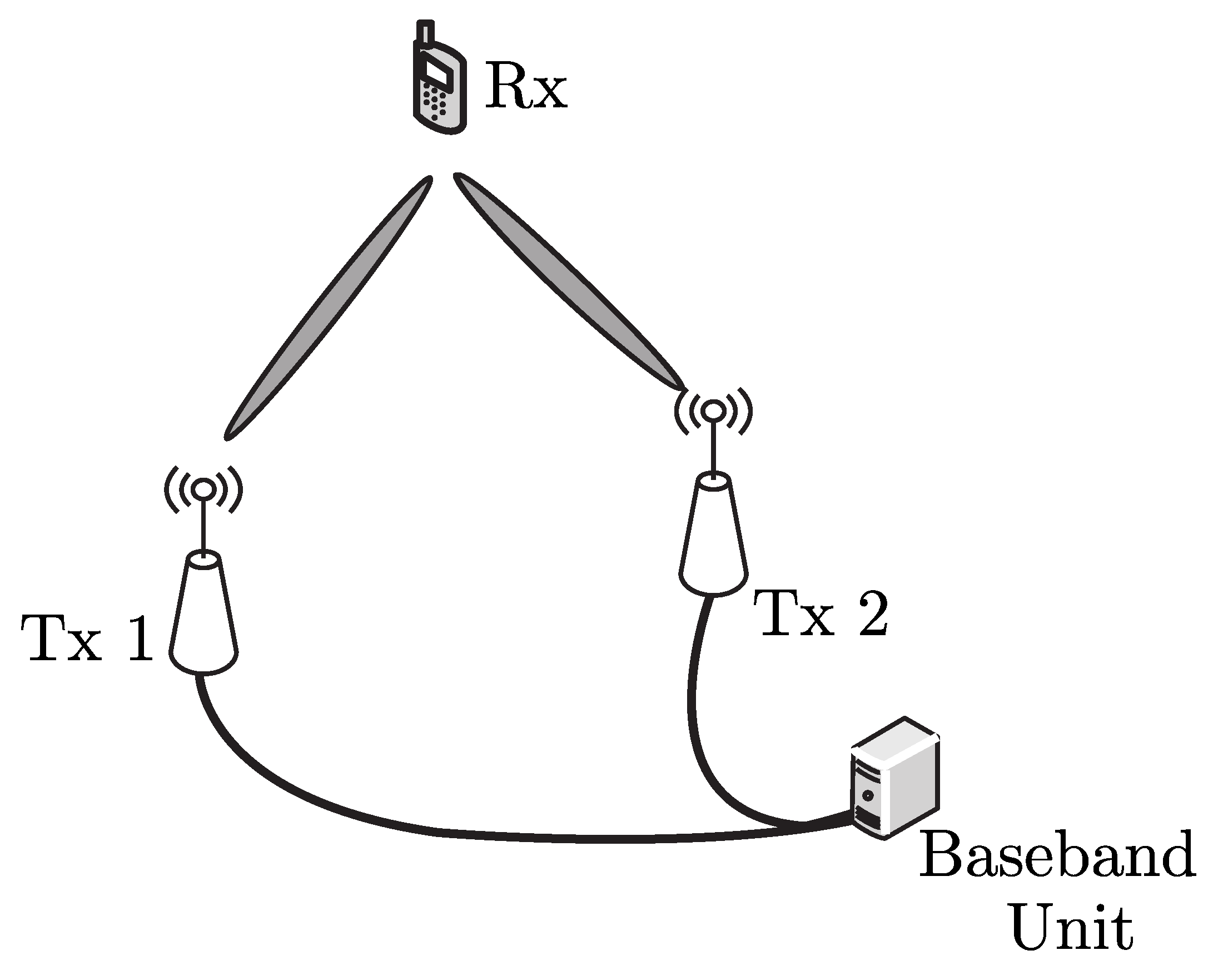
Multiple-input-multiple-output (MIMO) techniques have become a promising method to improve communication performances of mobile communication systems such as coverage, spectral efficiency, data rate, and reliability [1,2,3]. In conventional MIMO systems, multiple antennas are co-located in a single nodes, which provides diversity gain in multi-path fading channels. Chen et al. investigate the performance gain through maximal ratio combining (MRC) and selective combining (SC) under Rayleigh and Nakagami-m fading channels in [4,5], respectively. However, due to the co-located nature of the conventional MIMO, the multiple single-input-single-output (SISO) links undergo the same shadowing [6,7], which implies no macro-diversity gain can be exploited. To overcome this limitation, distributed antenna systems (DAS) were proposed to achieve spatial micro- and macro-diversity simultaneously. When it comes to cellular networks, as shown in Figure 1, DAS called remote antenna units (RAUs), which are inter-connected through high-quality wired or wireless links, are distributed in a cell [8,9] to extend coverage and improve the spectral efficiency.
Distributed antenna arrays can also be widely used in Internet-of-Things (IoT) networks with small nodes such as sensors and mobile devices [10]. Due to space and hardware limitations, multiple antennas cannot be accommodated in small devices. Instead, to mitigate fading channels, multiple nodes help another to transmit the same message, which is called cooperative transmission (CT). At the receiver of CT-based networks, multiple copies of the same message are combined at the physical layer, which provides signal-to-noise-ratio (SNR) advantage. Such SNR advantage can be used to improve throughput [11,12], transmission range [13,14,15], and energy efficiency [16,17,18,19]. In addition, if cooperative beamforming is applied to the DAS, sensitive message can be protected from eavesdropping [20,21]. Also, DAS is expected to provide better connectivity in millimeter wave channel in fifth-generation (5G) cellular networks [22,23,24].
Because of such advantages, DAS has been extensively studied in [8,9,25,26,27,28,29,30]. For example, Roh et al. analyzed the outage performance of DAS assuming composite Rayleigh-lognormal environments in [25]. Similarly, Chen et al. derived the downlink outage rates under composite Nakagami-m and lognormal channels [26,27]. Also, You et al. presented the spectral and transmit power efficiency of cooperative DASs in [8,9]. Coso et al. applied the DAS to wireless sensor networks and showed that cooperative DAS provides significant energy savings [28]. In addition, distributed MIMO multi-hop communication systems has been introduced by Dohler et al. in [29]. Choi et al. analyzed achievable capacity of DAS in an interference-limited multi-cell environments [30].
However, most of existing studies on DAS including aforementioned ones assumed that both small and large-scale fading channels are independent for links from separated DAS antennas to a receiver. For instance, in [25,26,27], the outage probability is derived assuming independent log-normal shadowing for distributed antenna arrays. However, in reality, shadowing in decibels has been measured to have significant correlation in various scenarios such as outdoor channels in rural and suburban environments at 1.9 GHz [31], indoor channels measured at the University of Auckland at 1.8 GHz [32], high-speed railway environments [33], and references therein. Such correlated shadowing affects handover behavior, interference power, and macro-diversity schemes [34]. Motivated by this fact, we investigate the impact of correlated shadowing in composite Rayleigh-lognormal environments for more realistic modeling and analysis of DASs. To be specific, the main contributions of this papers are three-fold. First, we present exact mathematical expressions for the received SNR and outage probabilities of DAS with an arbitrary shadowing correlation coefficient between zero and one. Second, assuming that the correlation of shadowing on DASs is an exponentially decaying function of the inter-separation between neighboring antenna elements, we show the trade-off between macro-diversity gain and increased path-loss. Third, through numerical results and simulation, we show that there exists an optimal inter-element separation that minimizes the outage probability of DAS with two different combining schemes.
2. System Model
2.1. Network Topology
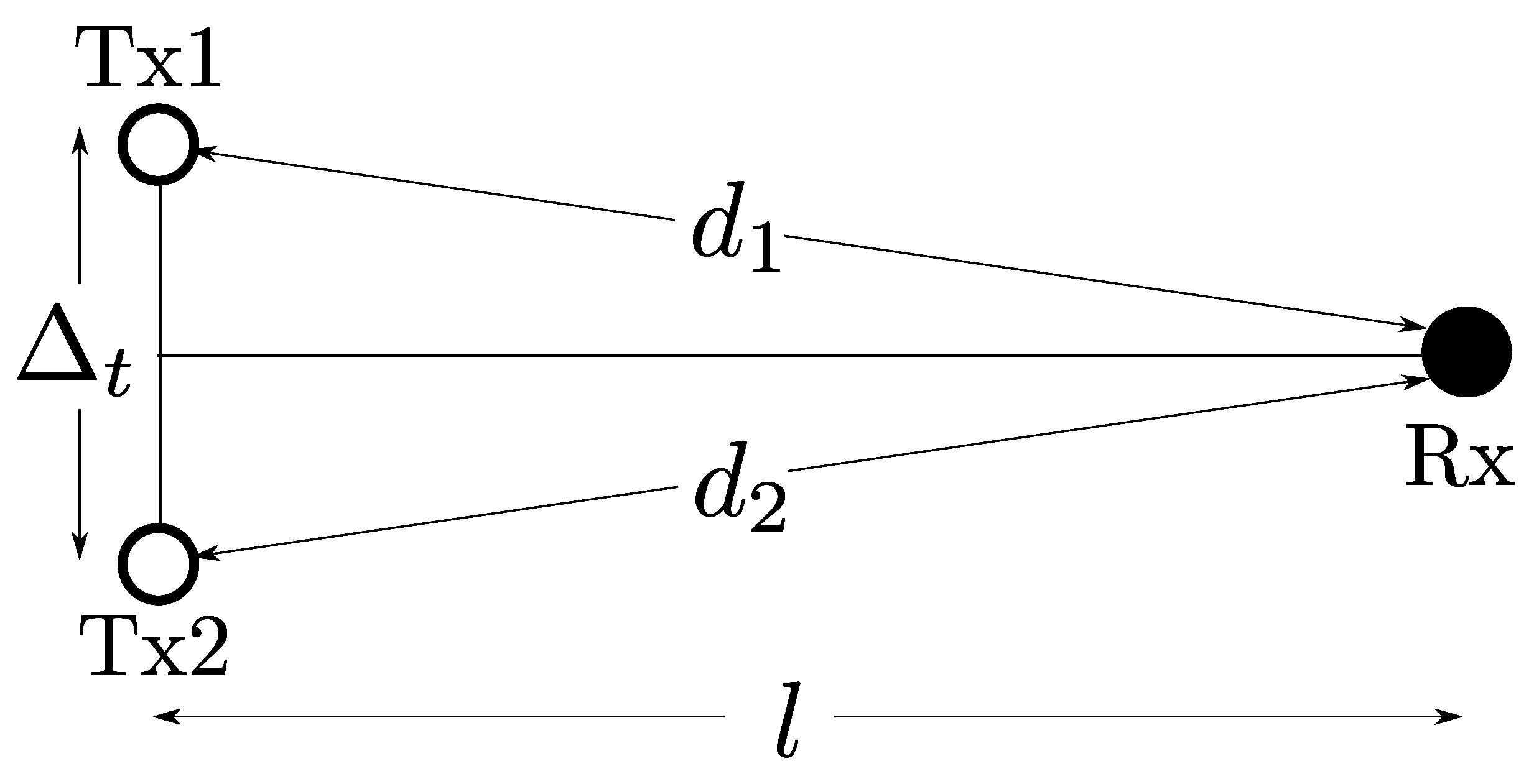
Following the dual diversity model in a log-normal shadowing channel in [35], we consider a multiple-input-single-output (MISO) communication link created by two transmitters (Txs) and one receiver (Rx), as shown in Figure 2. In the figure, the two white-filled circles indicate the cooperative transmitters, the separation between which is . Moreover, the receiver is indicated by the black circle, and the separation between the mid-point of the two transmitters and the receiver is l. The distance from Txi (for ) to Rx is , which determines the path loss between Txi to Rx.
2.2. Channel Model
Considering the widely dispersed DAS transmitters, we assume a composite fading channel with both small-scale and large-scale fading, which correspond to Rayleigh fading and log-normal shadowing, respectively. The received signal at the receiver is vector and noted as
where , and is the transmit power at each transmitter. Also, is the desired signal transmitted to the receiver, while is additive white Gaussian noise (AWGN) vector. We assume unit noise power for for simplicity. In addition, the channel vector is expressed as
where is the channel gain from Txi to Rx. As in [3], the composite fading channel can be modelled such that its power is decomposed into
where and represent the squared envelopes determined by small-scale and large-scale fading, respectively. We assume that small scaling fading follows Rayleigh fading, thereby the conditional probability density function of for given shadowing realization follows the exponential distribution ([3], Equation (2.7)), which is given by
where . On the other hand, we assume that shadowing follows log-normal distribution ([3], Equation (2.53)):
where and . Also, is the standard deviation of the log-normal shadowing in dB scale. In addition, is the mean of the log-normal shadowing in decibel (dB), which is determined by the path loss as
where n is the path-loss exponent.
2.3. Shadowing Correlation
In the presence of correlation between log-normal shadowing of two channels and , the joint probability density function (PDF) of and is given by
where and . Also, is correlation coefficient between and . If , the two channel and are uncorrelated, which corresponds to the joint probability density function as below:
In contrast, if , then following the marginal probability density function in (5). When , the diversity gain diminishes due to the correlated large-scale fading compared to the uncorrelated case (i.e., ).
According to Table 1 in [34], there are more than 20 shadowing correlation models in the existing literature. The simplest one is the constant model, in which is always fixed (e.g., in [36]). Also, the most common correlation model is a decaying exponential of distance (i.e., with a constant ), as in [13,37,38,39,40]. Extended from these models, more complex models are proposed. For example, Algans et al. used the sum of two independent exponential processes [41]. In [42], a model is proposed with for . On the other hand, the correlation is also argued to be a function of the angle spread of two diversity paths [43]. In addition to these models, there are several variants, as noted in the extensive survey in [34].
Among these large number of existing correlation models, we adopt the distance-based exponentially decaying model, because (i) it is the most widely-used model [34] and (ii) it allows analytical simplicity. (We note that this model might not be the most accurate model. Also, there is no single model that always accurately reflects various channel environments.) To be specific, following [13,40], we assume the correlation is an exponentially decaying function of the inter-element distance as:
where is the de-correlation distance, which is tunable depending on channel environments. As in [40], we assume m.
As noted in (10), the macro-diversity gain increases as due to smaller correlation . However, as increases, the path loss becomes more severe, because in (6) is a decreasing function of . Such increase in path loss by is greater with higher path-loss exponent n. For this reason, there may exist an optimal inter-separation between the two transmitters that minimizes the error probability.
3. Outage Rate Analysis
At the receiver, the receiver vector is combined to benefit from micro- and macro-diversity. We consider two combininig methods: maximal ratio combining (MRC), which maximizes the received SNR, and selective combining (SC), which is easier to implement compared to (MRC). When MRC is adopted, the combined SNR is the sum of the two squared envelopes [2,3,4,5] as
On the other hand, if selective combining is adopted, as noted in [2,3,4,5], the corresponding combined SNR is given by
The outage rate for a given SNR threshold is expressed as
where is the received SNR at the receiver. In the following sections, we derive the outage probabilities of non-cooperative and cooperative schemes.
3.1. Non-Cooperative Transmission
As the baseline of outage rate performance, we derive the outage probability of a single-input-single-output (SISO) link without cooperation. For such non-cooperative networks, the outage is given by
3.2. Maximal Ratio Combining
Because the small-scale fading for the two links, Tx1-Rx and Tx2-Rx, are independent, the received SNR follows a hypo-exponential distribution for given shadowing realizations and with the conditional cumulative distribution function (CDF) [16]:
where . Using this conditional probability density function, the outage probability for MRC is given by
which can be numerically integrated by applying the Gauss-Hermite formula [2,44]. If the both links undergo the same shadowing realization (i.e., ), the corresponding outage rate is expressed as
which can be numerically calculated through the Gauss-Hermite polynomials [2,44].
3.3. Selective Combining
In case that selective combining is used, the conditional CDF of is derived as
where . Therefore, the outage rate for SC is expressed as
which can be numerically calculated through the Gauss-Hermite formula [2,44]. As in MRC, when , the outage probability is simplified as
which can be readily calculated based on the Gauss-Hermite polynomials [2,44].
4. Numerical Results
To validate our analysis in the previous section, we compare numerical results of the analytical expressions with simulation results. For simulations, we randomly generate channel realizations to calculate an outage probability. The small-scale (multi-path) fading components for the two Tx-Rx links are generated independently, while the large-scale fading (shadowing) components are realized with a given correlation .
4.1. Outage Probability versus Transmit Power
Figure 3 shows the outage simulation results with increasing transmit power for 20 dB to 60 dB for the SNR threshold . Also, we set m, m, , and dB. In the figure, the black solid line represents the outage probability of the non-cooperative (SISO) transmission, in (14). Also, the blue solid and red dotted lines correspond to MRC and SC (i.e., and in (17) and (20)), respectively. The triangle and circle markers indicate the results with independent () and same shadowing channels (), respectively. Lastly, the square-markers represents the simulation results with .
First, the theoretical curves show excellent correlation with the simulated curves, which verifies our analysis in Section 3. Also, as expected, when the correlation of the log-normal shadowing increases, the outage performance becomes worse. For example, at , the gap between and is about 7 dB, while the results with , indicated by the curves with the squares, exist in between the curves with the circles and triangles. However, all of the cooperative schemes (even with ) perform significantly better compared to the non-cooperative transmission, because the cooperative transmission can benefit from the micro-diversity gain regardless of that determines the degree of the macro-diversity. Indicated by the slopes in the high SNR regime, the performance gap between the cooperative and non-cooperative algorithms would be larger, as the transmit power increases. In addition, when comparing the two combining techniques, for the same , MRC outperforms SC, because always holds [2].
4.2. Outage Probability Versus Inter-Separation between Transmitters
As discussed in Section 2.3, the greater makes macro-diversity gain increase, while the MISO link created by DAS suffers from higher path attenuation. For the reason, we delve into the impact of on the outage rate. In Figure 4, the horizontal axis represents from 1 to 50 m, while the vertical axis indicates the outage probability in a logarithmic scale. For the comparison purpose, the simulation results with and , which correspond to the curves with the circles and triangles respectively, are also illustrated. The results with are indicated by the curves with squares. Furthermore, the blue solid and red dotted lines represent the results with MRC and SC, respectively. The outage probabilities with and simply increase, as increases, because their path losses monotonically increase with fixed correlation of zero and one, respectively. However, for the same , the curves with show significantly smaller outage probabilities compared to those with , which can be explained by the different degree of macro-diversity.
The curves with determined by (10) first decrease for both MRC and SC, as increases, because of enhanced macro-diversity gain with smaller . Then, the outage curves increase again, as increases, since the path attenuation increases. Therefore, there exist an optimal , which corresponds to the minimum outage rate, as shown in the graphs. The simulation results show that both MRC and SC schemes have the same optimal inter-separation . The outage performance with is always upper bounded by with and lower bounded by with . In fact, as decreases, becomes similar to with . Furthermore, the outage rate approaches with independent shadowing, as increases, which implies that .
4.3. Optimal with Different Standard Deviation of Shadowing
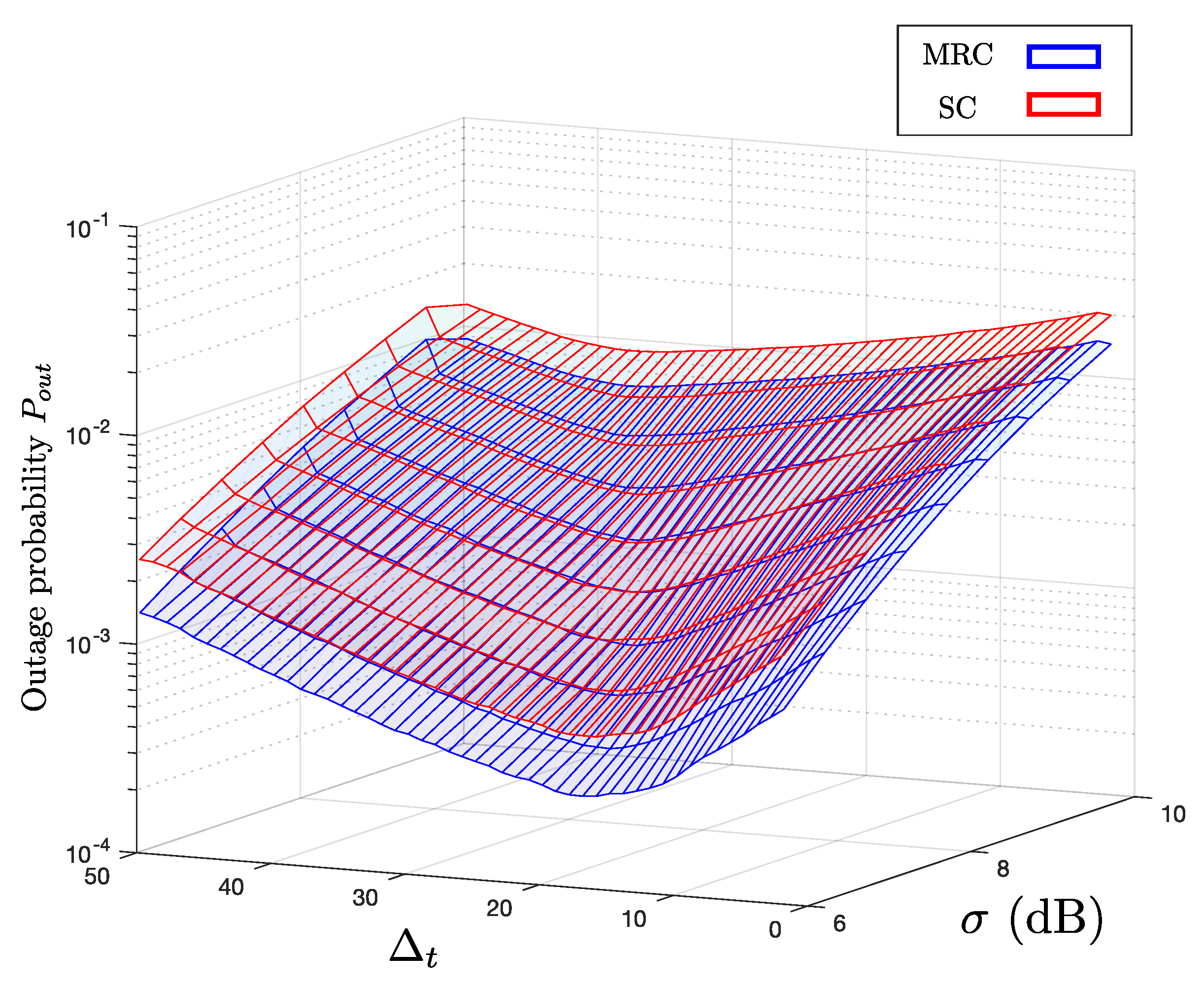
To better understand the trade-off between path loss and macro-diversity in correlated shadowing channels, we first investigate the impact of standard deviation of the log-normal shadowing. The higher implies more severe large-scale fading, thereby macro-diversity becomes more important. Figure 5 shows the outage probabilities with different and , which correspond to the x- and y-axes, respectively. The outage rates with MRC and SC are indicated by the blue and red meshed surfaces, respectively. As in the previous simulation results, the outage rate with MRC is always smaller than that with SC for the same condition. Also, when is fixed, increases as increases due to higher shadowing. On the other hand, for the same , there exists the optimal value of that minimizes .
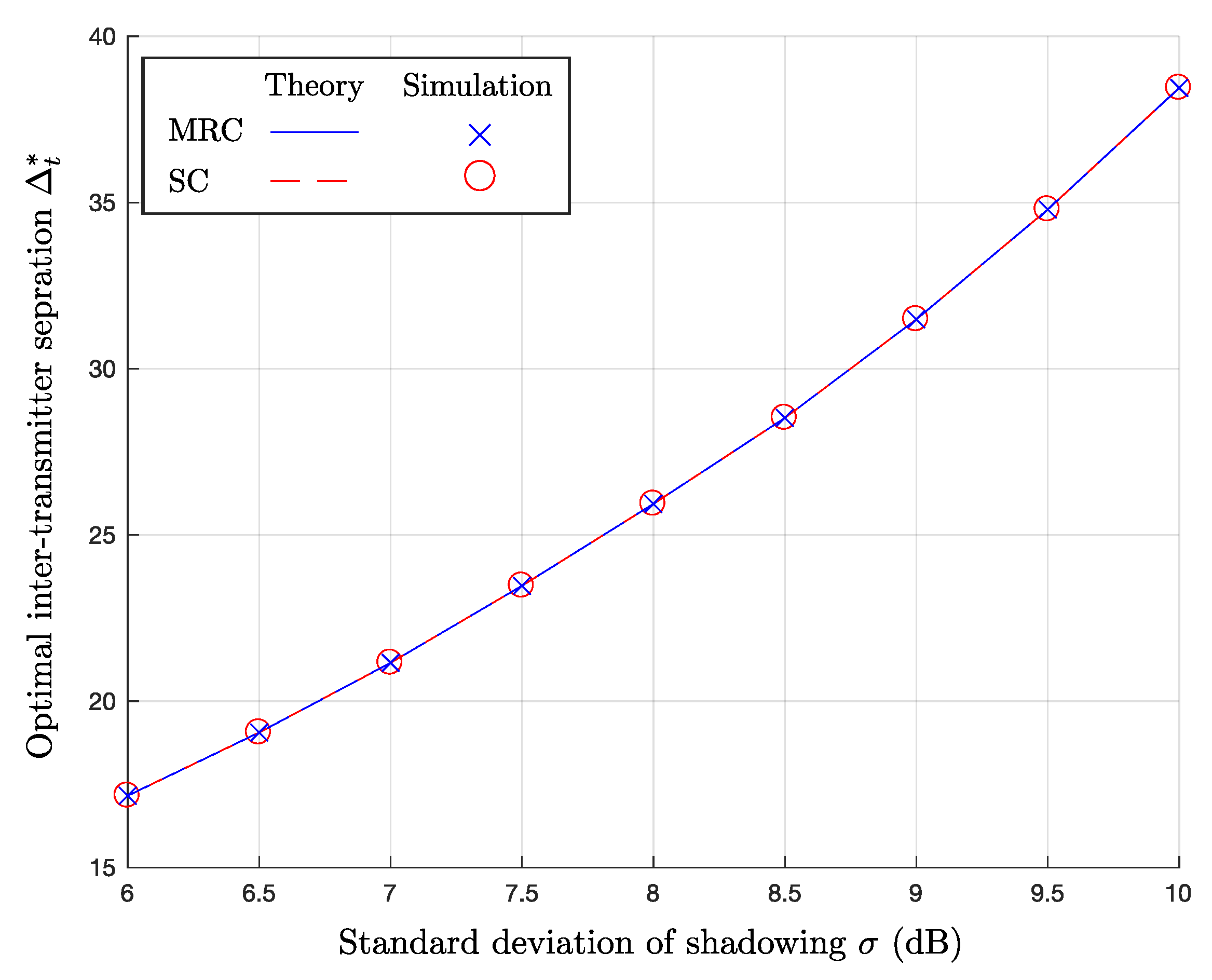
Figure 6 shows the optimal inter-transmitter separation as a function of in dB. The blue solid and red dotted lines represent the numerical results of MRC and SC based on our analysis, respectively. Furthermore, the blue ‘x’- and red ‘o’-markers indicate the simulation results of MRC and SC, respectively. As shown in the figure, the two combining schemes have the same optimal value, even though they give different . As increases, increases, because the impact of the large-scale fading becomes larger. Thus, to overcome such severe shadowing, macro-diversity gain with smaller , which means higher , is required.
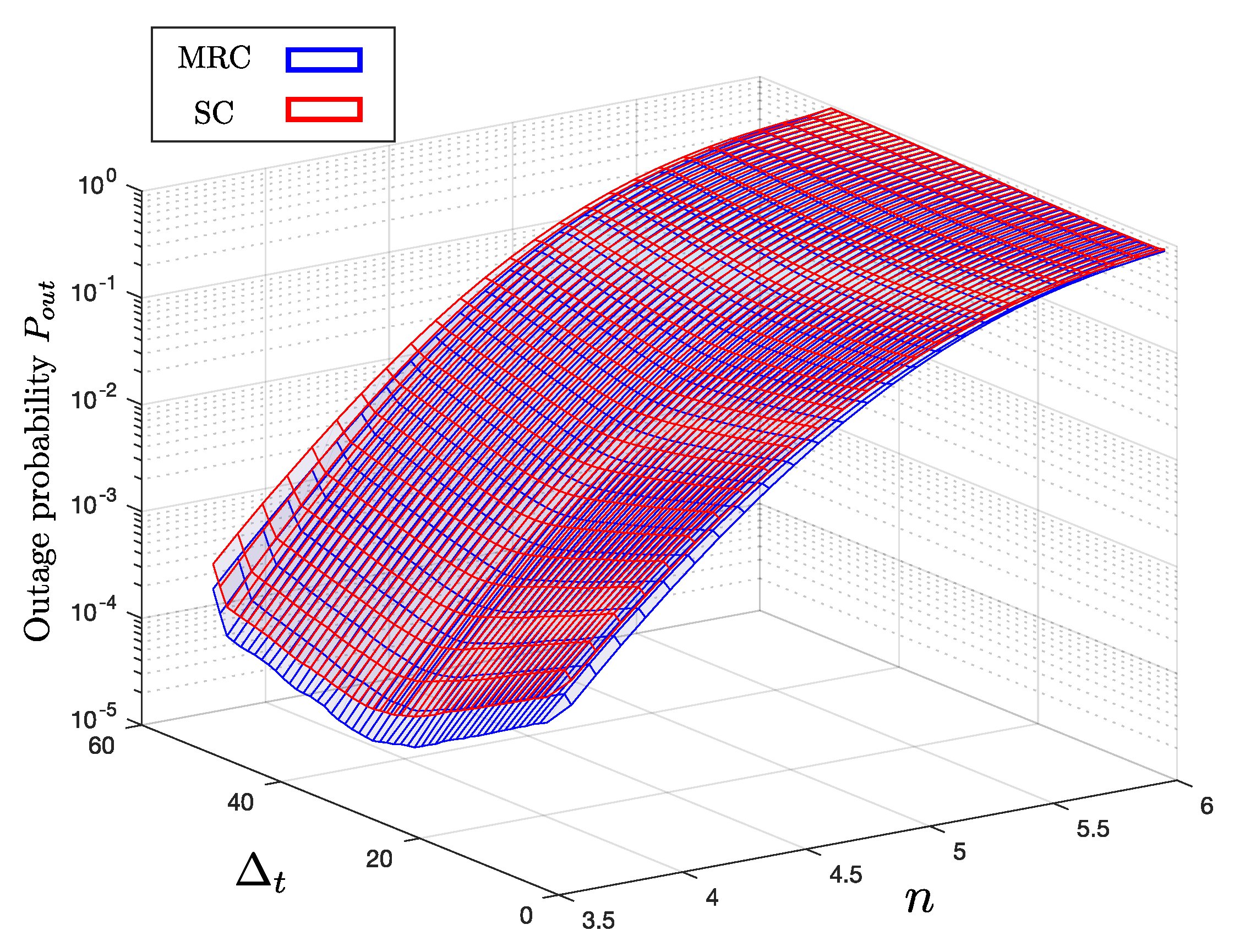
4.4. Optimal with Varying Path-Loss Exponent n
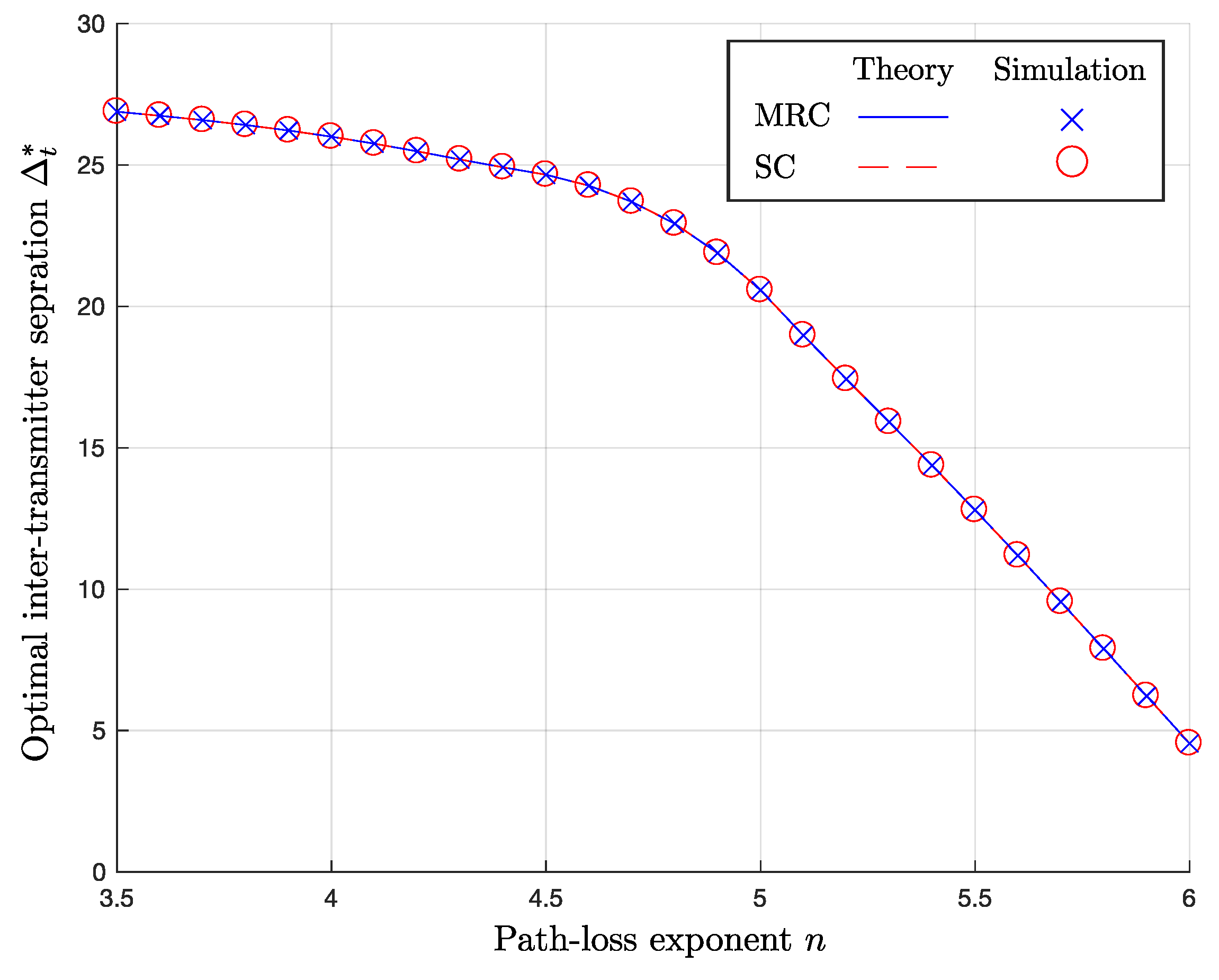
In Figure 7 and Figure 8, we observe the impact of the path-loss exponent n. Since path attenuation increases, as n increases, the performance degradation by increasing becomes more significant. As derived in analysis in Section 3, the outage rates increase, as n increases due to the increased path attenuation for the same distance, as indicated in Figure 7. As in the previous simulation results, the outage probability with MRC is always smaller compared that with SC. Furthermore, the shape of the surfaces tell us that there exists an optimal for a fixed n. Figure 8 illustrates how the optimal inter-separation varies under the change in n. As before, the curves with ‘x’- and ‘o’-markers indicate with MRC and SC, respectively. In general, for both MRC and SC, decreases as n increases, because the path attenuation becomes more important factor with higher n, while the impact of correlated shadowing remains the same. For the reason, when n is large, a method to take advantage of macro-diversity by incrementing is not as efficient as in the channel environments with small n.
5. Conclusions
In this paper, we analyze the impact of correlation in the large-scale fading on the DASs in composite fading channels characterized by Rayleigh and log-normal distributions. While the existing literature assumes independent shadowing for composite fading channels, the simulation results indicate that the correlated shadowing causes significant outage performance degradation, which requires more power up to 7 dB to achieve the same outage rates. Assuming a realistic shadowing correlation model that reflects measured data, we show that there exists an optimal inter-separation between the two transmitters in a dual diversity MISO link. In addition, through analysis and simulation, we present how the optimal inter-transmitter distance changes under variations in path loss exponent and standard deviations of shadowing. From the network-level system perspective, the observations in this paper should sensitize system designers to use more realistic physical-layer performance model. Possible future extensions include generalization of DAS configurations (i.e., MIMO channel with more than two transmit antennas) and investigation with more accurate but complex shadowing correlation models.
Author Contributions
The contributions of M.I. were to perform simulations and summarize the results, while H.J. advised the key ideas about the system model and crystallized mathematical framework and theoretical analysis.
Funding
This research was supported by Basic Science Research Program through the National Research Foundation of Korea (NRF) funded by the Ministry of Education (Grant number: NRF-2016R1D1A1B03930060).
Conflicts of Interest
The authors declare no conflict of interest.
Abbreviations
The following abbreviations are used in this manuscript:
| DAS | Distributed antenna system |
| MIMO | Multiple-input-multiple-output |
| IoT | Internet-of-Things |
| SISO | Single-input-single-output |
| MISO | multiple-input-single-output |
| RAU | Remote antenna unit |
| CT | Cooperative transmission |
| SNR | Signal-to-noise-ratio |
| 5G | Fifth-generation |
| Tx | Transmitter |
| Rx | Receiver |
| AWGN | Additive white Gaussian noise |
| Probability density function | |
| CDF | Cumulative distribution function |
| MRC | Maximal ratio combining |
| SC | Selective combining |
References
- Laneman, J.; Tse, D.; Wornell, G. Cooperative diversity in wireless networks: Efficient protocols and outage behavior. IEEE Trans. Inf. Theory 2004, 50, 3062–3080. [Google Scholar] [CrossRef]
- Stüber, G.L. Principles of Mobile Communication, 2nd ed.; Kluwer Academic Publishers: Alphen aan den Rijn, The Netherlands, 2001. [Google Scholar]
- Simon, M.K.; Alouini, M.-S. Digital Communication Over Fading Channels, 2nd ed.; Wiley-IEEE Press: Hoboken, NJ, USA, 2002. [Google Scholar]
- Chen, Z.; Yuan, J.; Vucetic, B. Analysis of transmit antenna selection/maximal-ratio combining in Rayleigh fading channels. IEEE Trans. Veh. Technol. 2005, 54, 1312–1321. [Google Scholar] [CrossRef]
- Chen, Z.; Chi, Z.; Li, Y.; Vucetic, B. Error performance of maximal-ratio combining with transmit antenna selection in flat Nakagami-m fading channels. IEEE Trans. Wirel. Commun. 2009, 8, 424–431. [Google Scholar] [CrossRef]
- Xing, W.; Wang, N.; Wang, C.; Liu, F.; Ji, Y. Co-channel interference of microcellular systems on shadowed Nakagami fading channels. In Proceedings of the IEEE VTC, Secaucus, NJ, USA, 18–20 May 1993. [Google Scholar]
- Hansen, F.; Meno, F.I. Mobile fading-Rayleigh and lognormal superimposed. IEEE Trans. Veh. Technol. 1977, 26, 332–335. [Google Scholar] [CrossRef]
- You, X.H.; Wang, D.M.; Sheng, B.; Gao, X.Q.; Zhao, X.S.; Chen, M. Cooperative distributed antenna systems for mobile communications: Coordinated and distributed MIMO. IEEE Wirel. Commun. 2010, 17, 35–43. [Google Scholar] [CrossRef]
- Wang, D.; You, X.; Wang, J.; Wang, Y.; Hou, X. Spectral efficiency of distributed MIMO cellular systems in a composite fading channel. In Proceedings of the IEEE ICC, Beijing, China, 19–23 May 2008; pp. 1259–1264. [Google Scholar]
- Sendonaris, A.; Erkip, E.; Aazhang, B. User cooperation diversity. Part I. System description. IEEE Trans. Commun. 2003, 51, 1927–1938. [Google Scholar] [CrossRef]
- Jung, H.; Weitnauer, M. Multi-packet opportunistic large array transmission on strip-shaped cooperative routes or networks. IEEE Trans. Wirel. Commun. 2014, 13, 144–158. [Google Scholar] [CrossRef]
- Jung, H.; Weitnauer, M.A. Multi-packet interference in opportunistic large array broadcasts over disk networks. IEEE Trans. Wirel. Commun. 2013, 12, 5631–5645. [Google Scholar] [CrossRef]
- Jung, H.; Chang, Y.; Ingram, M.A. Experimental range extension of concurrent cooperative transmission in indoor environments at 2.4 GHz. In Proceedings of the IEEE MILCOM, San Jose, CA, USA, 31 October–3 November 2010. [Google Scholar]
- Chang, Y.; Jung, H.; Ingram, M.A. Demonstration of a new degree of freedom in wireless routing: Concurrent cooperative transmission. In Proceedings of the HotEMNETS 2010 Workshop on Hot Topics in Embedded Networked Sensors, Killarney, Ireland, 28–29 June 2010. [Google Scholar]
- Jung, H. Experimentation and Physical Layer Modeling for Opportunistic Large Array-Based Networks. Ph.D. Thesis, School of Electrical and Computer Engineering, Georgia Institute of Technology, Atlanta, GA, USA, 2014. [Google Scholar]
- Jung, H.; Weitnauer, M.A. Characterization of path-loss disparity in virtual multiple-input-single-output links. Int. J. Antennas Propag. 2014, 2014, 650236. [Google Scholar] [CrossRef]
- Jung, H.; Weitnauer, M.A. SNR penalty from the path-loss disparity in virtual multiple-input-single-output (VMISO) link. In Proceedings of the IEEE ICC, Budapest, Hungary, 9–13 June 2013. [Google Scholar]
- Jung, H.; Weitnauer, M.A. Analysis of link asymmetry in virtual multiple-input-single-output (VMISO) systems. Ad Hoc Netw. 2017, 63, 20–29. [Google Scholar] [CrossRef]
- Lin, J.; Jung, H.; Chang, Y.J.; Jung, J.W.; Weitnauer, M.A. On cooperative transmission range extension in multi-hop wireless ad-hoc and sensor networks: A review. Ad Hoc Netw. 2015, 29, 117–134. [Google Scholar] [CrossRef]
- Jung, H.; Lee, I.-H. Analog cooperative beamforming with spherically-bound random arrays for physical-layer secure communications. IEEE Commun. Lett. 2018, 22, 546–549. [Google Scholar] [CrossRef]
- Jung, H.; Lee, I.-H. Secrecy rate of analog collaborative beamforming with virtual antenna array following spatial random distributions. IEEE Wirel. Commun. Lett. 2018. [Google Scholar] [CrossRef]
- Jung, H.; Lee, I.-H. Outage analysis of multihop wireless backhaul using millimeter wave under blockage effects. Int. J. Antennas Propag. 2017, 2017, 4519365. [Google Scholar] [CrossRef]
- Jung, H.; Lee, I.-H. Connectivity analysis of millimeter-wave device-to-device networks with blockage. Int. J. Antennas Propag. 2016, 2016, 7939671. [Google Scholar] [CrossRef]
- Jung, H.; Lee, I.-H. Outage analysis of millimeter-wave wireless backhaul in the presence of blockage. IEEE Commun. Lett. 2016, 20, 2268–2271. [Google Scholar] [CrossRef]
- Roh, W.; Paulraj, A. Outage performance of the distributed antenna systems in a composite fading channe. In Proceedings of the IEEE VTC, Vancouver, BC, Canada, 24–28 September 2002. [Google Scholar]
- Chen, H.M.; Wang, J.B.; Chen, M. Downlink outage probability of distributed antenna systems over shadowed Nakagami-m fading channels with antenna selection. In Proceedings of the International Conference on Wireless Communications & Signal Processing, Nanjing, China, 13–15 November 2009. [Google Scholar]
- Chen, H.M.; Wang, J.B.; Chen, M. Performance analysis of the distributed antenna system with antenna selective transmission over generalized fading channels. In Proceedings of the IEEE International Conference on Wireless Communications & Signal Processing, Nanjing, China, 13–15 November 2009. [Google Scholar]
- Coso, A.D.; Spagnolini, U.; Ibars, C. Cooperative distributed MIMO channels in wireless sensor networks. IEEE J. Sel. Areas Commun. 2007, 25, 402–414. [Google Scholar] [CrossRef] [Green Version]
- Dohler, M.; Gkelias, A.; Aghvami, H. A resource allocation strategy for distributed MIMO multi-hop communication systems. IEEE Commun. Lett. 2004, 8, 99–101. [Google Scholar] [CrossRef]
- Choi, W.; Andrews, J.G. Downlink performance and capacity of distributed antenna systems in a multicell environment. IEEE Trans. Commun. 2007, 6, 69–73. [Google Scholar] [Green Version]
- Xing, W.; Wang, N.; Wang, C.; Liu, F.; Ji, Y. Shadow fading correlation between uplink and downlink. In Proceedings of the IEEE VTC, Rhodes, Greece, 6–9 May 2001. [Google Scholar]
- Butterworth, K.S.; Sowerby, K.W.; Williamson, A.G. Correlated shadowing in an in-building propagation environment. Electron. Lett. 1997, 33, 420–422. [Google Scholar] [CrossRef]
- He, R.; Zhong, Z.; Ai, B.; Oestges, C. Shadow fading correlation in high-speed railway environments. IEEE Trans. Veh. Technol. 2015, 64, 2762–2772. [Google Scholar] [CrossRef]
- Szyszkowicz, S.S.; Yanikomeroglu, H.; Thompson, J.S. On the feasibility of wireless shadowing correlation models. IEEE Trans. Veh. Technol. 2010, 59, 4222–4236. [Google Scholar] [CrossRef]
- Alouini, M.S.; Simon, M.K. Dual diversity over log-normal fading channels. IEEE Trans. Commun. 2002, 50, 1946–1959. [Google Scholar] [CrossRef]
- Szyszkowicz, S.S.; Yanikomeroglu, H. Limit theorem on the sum of identically distributed equally and positively correlated joint log-normals. IEEE Trans. Commun. 2009, 57, 3538–3542. [Google Scholar] [CrossRef]
- Baum, D.; Hansen, J.; Salo, J. An interim channel model for beyond- 3G systems: Extending the 3GPP spatial channel model (SCM). In Proceedings of the IEEE VTC, Stockholm, Sweden, 30 May–1 June 2005. [Google Scholar]
- Salo, J.; Vuokko, L.; El-Sallabi, H.M.; Vainikainen, P. An additive model as a physical basis for shadow fading. IEEE Trans. Veh. Technol. 2007, 56, 13–26. [Google Scholar] [CrossRef]
- Ni, W.; Zou, W.; Wang, H. Modeling of spatially cross-correlated shadow fading in distributed radio access networks. In Proceedings of the IEEE ICC, Beijing, China, 19–23 May 2008. [Google Scholar]
- Jalden, N.; Zetterberg, P.; Ottersten, B.; Hong, A.; Thoma, R. Correlation properties of large scale fading based on indoor measurements. In Proceedings of the IEEE WCNC, Kowloon, China, 11–15 March 2007; pp. 1894–1899. [Google Scholar]
- Algans, A.; Pedersen, K.; Mogensen, P. Experimental analysis of the joint statistical properties of azimuth spread, delay spread, and shadow fading. IEEE J. Sel. Areas Commun. 2002, 20, 523–531. [Google Scholar] [CrossRef]
- Catrein, D.; Mathar, R. Gaussian random fields as a model for spatially correlated log-normal fading. In Proceedings of the IEEE ATNAC, Adelaide, Australia, 7–10 December 2008. [Google Scholar]
- Haleem, M.; Avidor, D.; Valenzuela, R. Fixed wireless access system with autonomous resource assignment. In Proceedings of the IEEE PIMRC, Boston, MA, USA, 8–11 September 1998. [Google Scholar]
- Abramowitz, M.; Stegun, I.A. Handbook of Mathematical Functions 10th Printing with Corrections; Dover: Mineola, NY, USA, 1972. [Google Scholar]
Figure 1.
An example illustration of a distributed antenna system (DAS).

Figure 2.
Network topology model.

Figure 3.
Outage probability versus transmit power , when , m, m, , and dB.

Figure 4.
Outage probability versus inter-separation between the transmitters , when , m, dB, , and dB.
Figure 4.
Outage probability versus inter-separation between the transmitters , when , m, dB, , and dB.

Figure 5.
Outage probability with different and , when , m, dB, and .

Figure 6.
Optimal Inter-transmitter separation versus , when , m, dB, and .

Figure 7.
Outage probability with different and n, when , m, dB, and dB.

Figure 8.
Optimal Inter-transmitter separation versus path-loss exponent n, when , m, dB, and dB.

© 2018 by the authors. Licensee MDPI, Basel, Switzerland. This article is an open access article distributed under the terms and conditions of the Creative Commons Attribution (CC BY) license (http://creativecommons.org/licenses/by/4.0/).
Share and Cite
MDPI and ACS Style
Imran, M.; Jung, H. Outage Analysis of Distributed Antenna Systems in a Composite Fading Channel with Correlated Shadowing. J. Sens. Actuator Netw. 2018, 7, 32. https://doi.org/10.3390/jsan7030032
AMA Style
Imran M, Jung H. Outage Analysis of Distributed Antenna Systems in a Composite Fading Channel with Correlated Shadowing. Journal of Sensor and Actuator Networks. 2018; 7(3):32. https://doi.org/10.3390/jsan7030032
Chicago/Turabian StyleImran, Muhammad, and Haejoon Jung. 2018. "Outage Analysis of Distributed Antenna Systems in a Composite Fading Channel with Correlated Shadowing" Journal of Sensor and Actuator Networks 7, no. 3: 32. https://doi.org/10.3390/jsan7030032
Note that from the first issue of 2016, this journal uses article numbers instead of page numbers. See further details here.