The Space Mission Design Example Using LEO Bolos

ISAS/JAXA, Yoshinodai 3-1-1, Chuuou-ku, Sagamihara-shi 252-5210, Kanagawa-ken, Japan
Aerospace 2014, 1(1), 31-51; https://doi.org/10.3390/aerospace1010031
Submission received: 18 October 2013
/
Revised: 13 December 2013
/
Accepted: 13 December 2013
/
Published: 27 December 2013
Abstract
:Four sample space launch missions were designed using rotating momentum transfer tethers (bolos) within low Earth orbit and a previously unknown phenomenon of “aerospinning” was identified and simulated. The momentum transfer tethers were found to be only marginally more efficient than the use of chemical rocket boosters. Insufficient power density of modern spacecrafts was identified as the principal inhibitory factor for tether usage as a means of launch-assistance, with power densities at least 10 W/kg required for effective bolos operation.
1. Introduction: Previous Research on Momentum-Transfer Tethers
After 56 years of space exploration, the space launch industry remains reliant only on chemical rockets. This paper will investigate if any merit exists in implementing an alternative launch assist technology with functionality of existing upper stages—momentum transfer tethers.
For this purpose, Section 1 reviews the literature on the tether-assisted propulsion. Section 2 quantifies how specifics of the LEO (low-earth orbit) environment—a relatively dense atmosphere with a small density scale—along with micrometeoroids will affect operations of the tethers. Section 3 discusses the demerit of implementing tip masses or counterweights on momentum-transfer tether. Section 4 reviews the literature on the proper calculation of the tether tensile strength. Section 5 reviews existing solutions for the payload capture using tethers, and an original solution, based on a mid-air satellite retrieval system is proposed. In Section 6, four example orbital launch missions with momentum-transfer tethers are designed and their parameters analyzed. Section 7 concludes on the areas of development most critical for future implementation of the momentum-transfer tethers as launch assistance means.
In 2003, Frisbee [1] stated that the necessity to create a sustainable (high launch-rate) infrastructure was historically the delay to both launch-assist catapults and tether-assisted propulsion. The concept of an earth-based catapult typically has multi-GW electrical power requirements, due the necessity of launching crafts heavy enough to pierce the Earth’s atmosphere. In 2013, Powell, with the StarTram team [2], promoted a design with peak electrical power of 104 GW, and that power cannot be scaled down to any reasonable (10–100 MW) range. However, momentum-transfer tethers operate at near-vacuum and can be implemented even with currently meager energy technology. However, how high must the launch rate be? Do the recent advances in ion propulsion and high-strength polymers improve the merit of momentum transfer tethers? Are rotating tethers stable? Let’s try to answer these questions, starting with a review of already completed research related to space tethers.
Experiments were performed in space to master tether deployment. The work of Gates, in 2001 [3], stresses the importance of fast (>1 m/s) deployment to avoid problems with built-in stresses and electric charges. The longest tether stably deployed to date has reached a length of 31.7 km, albeit unintentionally [4]. According to Aerospace America Magazine [5], in 2010, the near-term target was to achieve reliable deployment and operation of 1 km tethers, although other projects [6] succeeded with non-librating deployment of 20 km-long tethers in 1993. In 2007, Menon [7] described in detail a tether brake used to control deployment of the 31.7 km-long tether in the SpaceMail experiment [4].
Therefore, the author concludes that current technology is sufficient to deploy 10–20 km-long tethers in the LEO environment.
Although significant research has been conducted by the scientific community on hanging or librating tethers for momentum transfer, in 1888, Wiesel [8] proved that optimal orbital transfer was achieved using a tether with constant tension during the entire transfer process. Therefore, all hanging and librating tether configurations were marked as less efficient, in terms of momentum transfer, for a given tether mass.
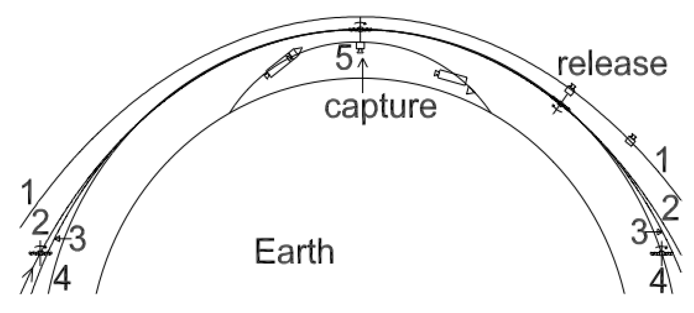
Among many rotating momentum-transfer tether configurations promoted on the Tether Unlimited site, the LEO bolo (rotating tether) [9,10] deserves special attention, as it is scalable to low tip speed. The orbital geometry of the LEO bolo is shown in Figure 1. The tether of the LEO bolo is also reusable; although, in 2010, Williams [11] proposed using a system with two rotating tethers for orbital capture—one disposable and one reusable. However, non-reusable tethers must be orders-of-magnitude stronger than existing ropes to be mass-effective as means of momentum transfer.
The LEO bolo can even operate the propellant-free, extracting momentum necessary for orbital transfer from the momentum of bodies in higher orbits. Unfortunately, around the Earth, the only such body is the moon, and series of tethers able to handle at least 1.6 km/s tip speed are necessary for harnessing the orbital momentum of the moon rocks. An example of momentum-neutral tether design may be found in [12]. Even for sub-km/s delta-v offered by bolo configurations built with existing materials, a MXER (magnetic-exchange electrodynamic reboost) drive option [10] still exists. But MXER is highly speculative research; Sorensen, in 2003 [10], lists several components of the MXER bolo as having a NASA TRL (technology readiness level) equal to 3 (only proof-of concept available), and two key technologies (tether coating and tether libration control) having a TRL equal to 2 (only technology concept was formulated). In addition, a high degree of difficulty (III) in R&D is expected for many components. Therefore, alternative engineering approaches to MXER should be considered first. The author favors modern ion motors as near-term alternatives to momentum-neutral or MXER systems.
Figure 1.
Orbital geometry of the LEO bolo (rotovator) launch assistance mission. (1) payload post-release orbit; (2) tether pre-capture orbit; (3) tether and payload post-capture orbit; (4) tether post-release orbit (circular); (5) payload pre-capture sub-orbital trajectory.
Figure 1.
Orbital geometry of the LEO bolo (rotovator) launch assistance mission. (1) payload post-release orbit; (2) tether pre-capture orbit; (3) tether and payload post-capture orbit; (4) tether post-release orbit (circular); (5) payload pre-capture sub-orbital trajectory.

The problem of rotating bolo (rotovator) stability has been extensively discussed by the research community. In 1996, Luo [13] described an extreme wealth of rotating tether vibration types. Such vibrations may easily result in tether straying from the correct capture or release point, or may even result in tether breakage. Therefore, two parametric measures should be taken. Firstly, a material with low accumulation of elastic energy (i.e., high rigidity) should be used for the tether. Secondly, a damper should be used as most rigid materials themselves have very low internal mechanical energy dissipation. In 1995, Puig-Suari [14] stated that, even after implementation of critical dampening, peak load due to tether vibrations exceeds steady-state load by 50%. Of course, aero-capture, as in [14], is the worst case, in terms of vibration excitation, but some vibration will be excited in the LEO bolo, as well, with each dip of the tether arm in the deeper layers of atmosphere. Even changes of tether temperature due to entering sunlight or shadow may result in vibration, which ultimately must be damped. In 1995, Tyc [15] speculated that large flexible booms attached to the tether, OEDIPUS-A, acted as a surprisingly effective dampening mechanism because of their high-frequency, high-strain whipping oscillations induced by the oscillations of the tether. In 1997, Vigneron [16] proposed and experimentally verified the stability criteria for a rotating tether holding a payload. His findings can be summarized as a statement of vibration instability of any tether that is too long or rotating too slowly. Both, faster rotation and smaller length contribute to larger natural dampening factors. In 1991, Matteis [17] demonstrated that tether dampening is rather ineffective in suppressing fundamental transverse (libration) mode (approximately a period of 400 s for an 80 km tether), although modes with higher frequency, including longitudinal vibration modes, can be effectively suppressed. Therefore, it is important for a tether system to avoid periodic forcing at or near fundamental transverse mode frequency. Such periodic forcing may happen due to atmospheric interaction as soon as the tether tip dips into the more dense atmospheric layers. In 2003, Takeuchi [18] stated that although librations of uncontrolled tethers on elliptical orbits are inevitable, with periodic thrust applied on the tether tips, these librations can be suppressed in cases of massless tethers. In addition, Takeuchi [18] found the steady-state rotating tether solution similar to that described in Section 2, but did not quantify it. By a superposition principle, stabilization of a librating massive tether on an elliptical orbit may require a periodic thrust distributed across the length of the tether. In 1987, Martinez-Sanchez [19] demonstrated that tether stability in an orbital plane may be maintained by reeling/unreeling the tether as well.
Therefore, the author concludes that LEO bolo may rotate (but not liberate) predictably if excessive lengths (beyond 100 km) are not considered.
2. The LEO Environment: Drag, Momentum Buildup (Aerospinning), and Meteoroids
This section complements the technical designs of momentum transfer tethers in Section 1 with the discussion on physical specifics of the tether operations in the LEO environment. Tether lifetime and tether rotation speed stability will be quantified in the current Section.
Engineers accustomed to the LEO mission design are familiar with the phenomenon of air drag. Air drag impacts much of the lifetime and requirements for propulsion for all LEO spacecrafts. However, often overlooked, is the rotation momentum imparted on the LEO tethers by air drag.
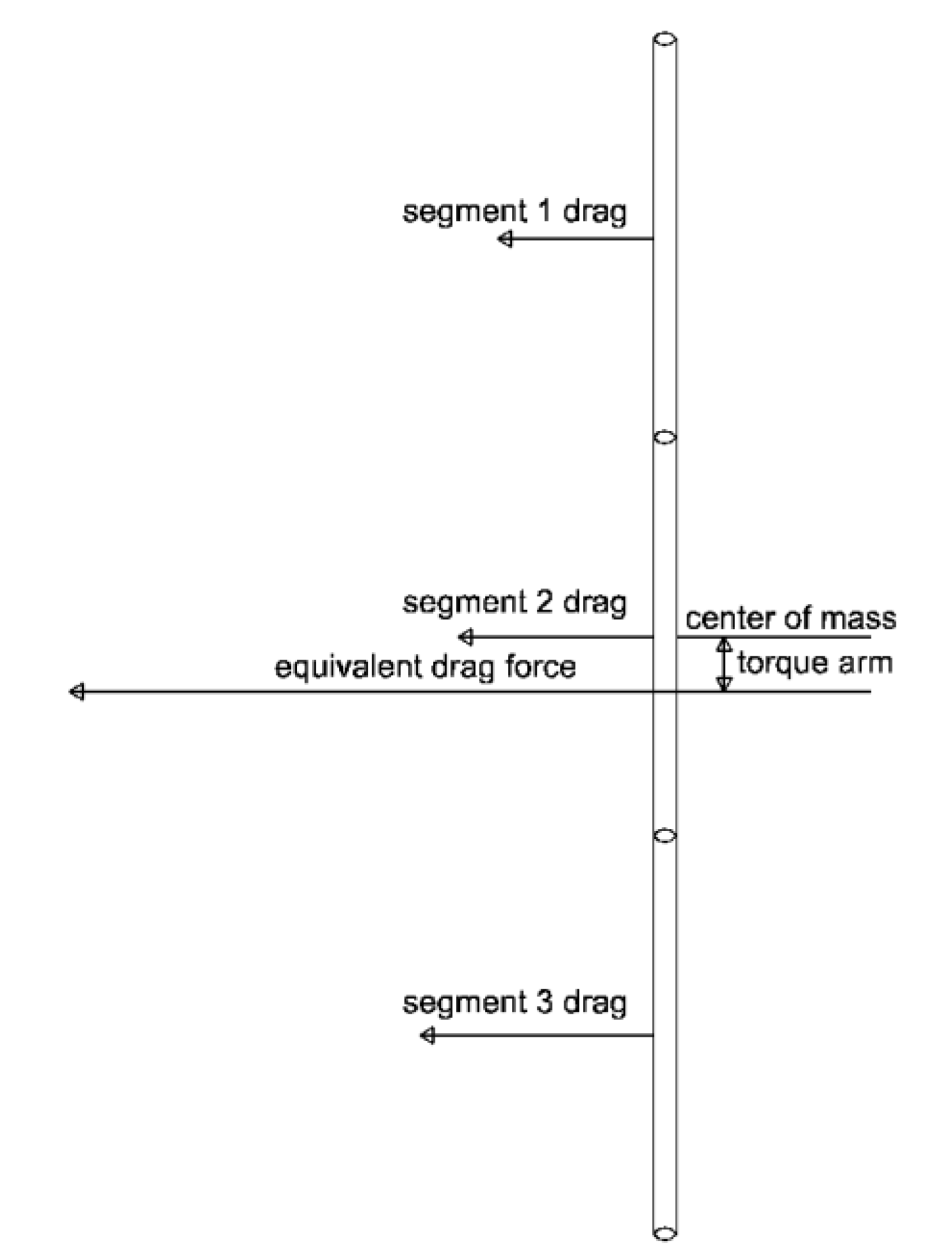
The rotation momentum buildup (aerospinning) phenomenon is defined as self-sustained and self-limited prograde rotation of an object in orbit due to its interaction with the density gradient of the atmosphere. Intuitively, rotation torque appears as the lower portion of the tether encounters denser air. Therefore, the center of pressure is initially below the tether’s center of mass. The diagram of forces resulting in aerospinning is shown in Figure 2. The smaller atmosphere density scale and longer tethers will result in the rotation momentum becoming significant. Such a mechanism always rotates a tether in prograde direction, resulting in the lower parts of the tether having progressively lower air velocities. As tether rotation speed increases, the center of pressure moves up until equilibrium rotation speed is reached with the center of pressure coincident with the center of mass. The unsteady process before reaching the equilibrium rotation speed may include libration and variable-speed rotation (as described by Takeuchi in [18]) and to call this “spin-up” is proposed by the author.
Figure 2.
The diagram of forces resulting in tether aerospinning.

The role of atmosphere in tether angular movement did not go unnoticed previously. In 1949 and 1972, Philips [20] and Stevens [21], respectively, stated the theoretical possibility of self-sustained transverse oscillations in tensioned tethers, if tangential airspeed exceeds the speed of the transverse waves in the tether. As a solution, Stevens [21] recommended providing separation between fundamental longitudinal and transverse frequencies to avoid large-amplitude cross-coupled oscillations induced by airflow. In 2004, Jokic [22] simulated the spin-up of tethers due to interaction with the planetary atmosphere, although only for transient interaction during the aero-capture. In 1997, Puis-Suari [23] also demonstrated that tethers may be rotated by the transient interaction with the atmosphere. Overall, members of the research community to date have acknowledged the possibility of tether rotation initiation because of the interaction with the airflow, but failed to see the self-limiting nature of such a rotation, and the principal role of the atmospheric density gradient in initiating and sustaining a rotation.
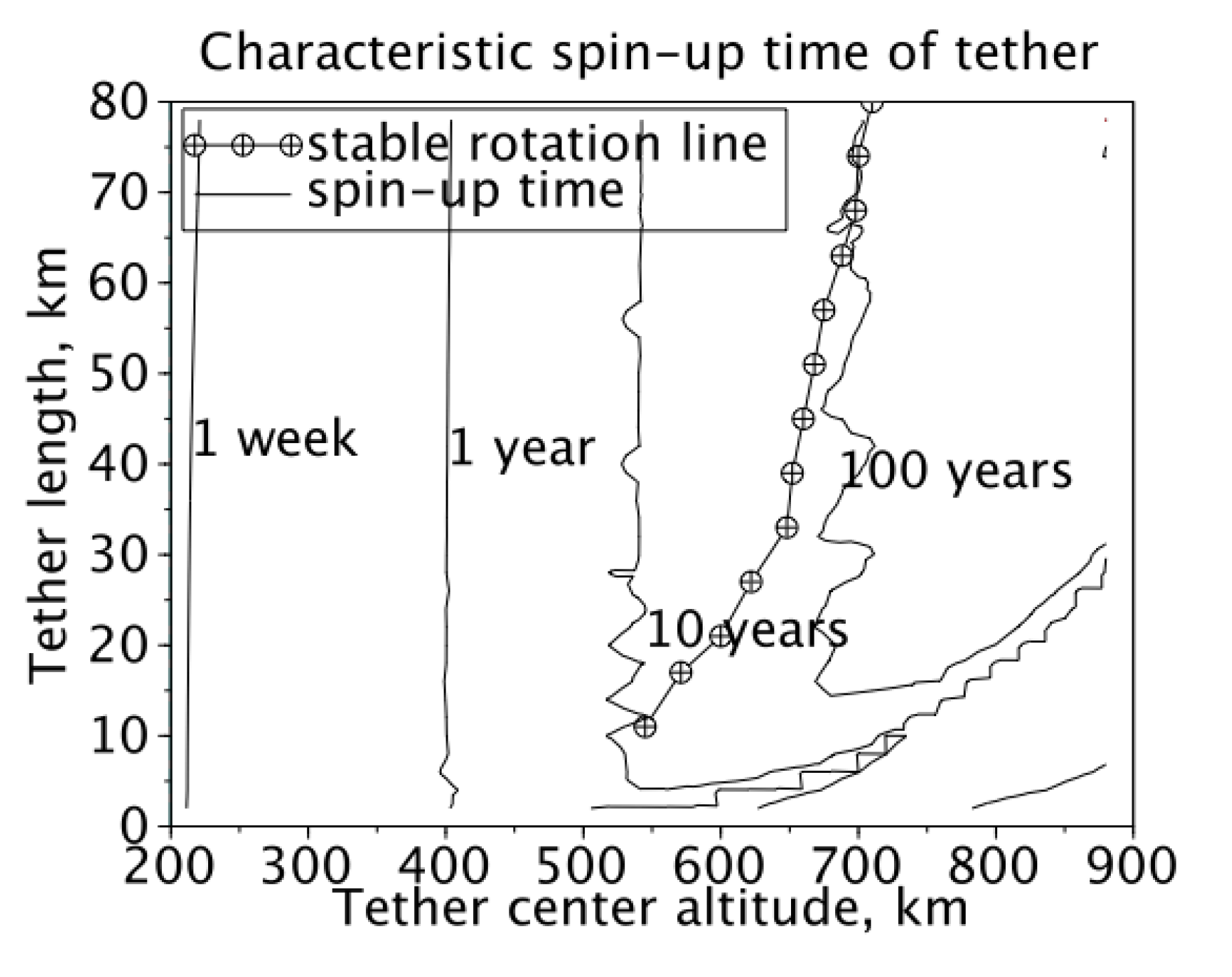
Both, air drag and air-induced torque, are dependent on the ratio between spacecraft (tether) unit mass and cross-sectional area. For unity surface divided by mass, both, drag and momentum have an associated characteristic time. These are: time to reentry for air drag, and steady angular speed divided by initial angular acceleration for air-induced momentum (called a characteristic spin-up time in Figure 5).
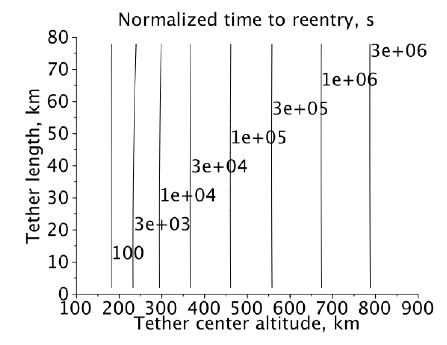
The author has simulated normalized (1 kg weight and 1 m2 ram area tethers) reentry and spin-up times using the numerical integration in conjunction with the MSISE-90 atmospheric model. The simulation results of reentry time and aerospinning steady-state tip speed are presented in Figure 3 and Figure 4, respectively. For the lower atmosphere (below 400 km) it was found that the characteristic spin-up time to reentry time ratio is close to 1000, but tends to decrease in the upper atmosphere. Such a large “drag-to-spin” ratio indicates what spin-up phenomenon will manifest itself only after several orbital re-boosts, if re-boosting force is applied to the center of mass. Hence, it is possible to cancel aerospinning by slightly offsetting the re-boost engine thrust axis from the tether center of mass, although at the cost of added engineering complexity.
Figure 3.
The normalized reentry time for tethers on equatorial circular orbits.

As the numerical integration algorithm may suffer from high sensitivity to input parameter variations, the orbital lifetime model was verified against Table I-1 in [24]. No discrepancy was found for small tether lengths, indicating general stability of reentry (and therefore, air drag) numerical integration. For longer tethers, at altitudes below 200 km, a braking effect of the tether tip entering dense layers of atmosphere become noticeable, while, for higher altitudes, drag was only slightly dependent on tether length because of the longer atmospheric density scale in the thermosphere. Additional drag is rather small as, for normalized tethers, additional drag in inhomogeneous atmospheres is the second-order correction to the drag of compact surfaces. This additional drag is visible in Figure 3 as a slight curvature of the reentry time contours below 3000 s of normalized reentry time.
Figure 4 shows the steady-state speed of the tether tip for average solar activity. Solar activity greatly changes the density scale of the upper atmosphere. Therefore, the indicated speeds can vary as much as three times those at low solar activity (resulting in greater speeds at low orbits) and high solar activity (resulting in lower speeds at low orbits). However, as the molar weight of the upper atmosphere is increased during the solar maximum, an altitude range (550–750 km) exist such that the effects of increased temperature and increased molar weight roughly cancel each other, resulting in a more stable atmospheric density scale and, therefore, a relatively stable steady-state rotation speed.
Figure 4.
Steady-state tip speed of the rotating tether on the equatorial circular orbit in average solar conditions (based on MSISE-90 atmospheric model).
Figure 4.
Steady-state tip speed of the rotating tether on the equatorial circular orbit in average solar conditions (based on MSISE-90 atmospheric model).
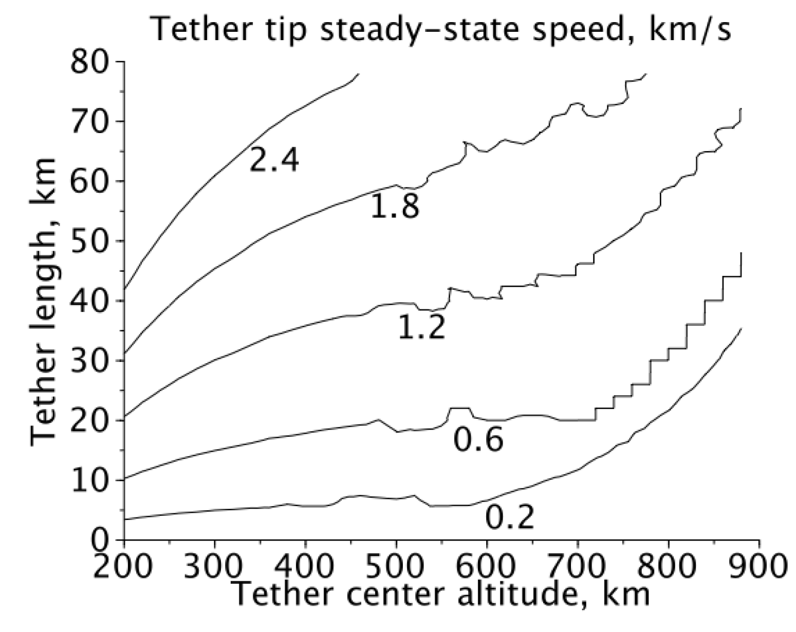
The important feature visible on Figure 5 is the range of orbit altitudes and tether lengths, whereby the steady-state rotation speed of the tether is nearly independent of the phase of the solar cycle. At this range, the tethers will rotate in a steady-state, with a period of roughly 170 s. Due to the large (compared to the Solar cycle period) spin-up time scale, it is expected that tethers on the rotation stability line will experience variability of their steady-state tip speed below 10%.
Figure 5.
The characteristic spin-up time of tethers on equatorial circular orbits.

Due to the gravity gradient stabilization, tether rotation cannot begin spontaneously as deployed. An initial tether angular velocity must be supplied by the momentum wheel or tip jet to start the rotation.
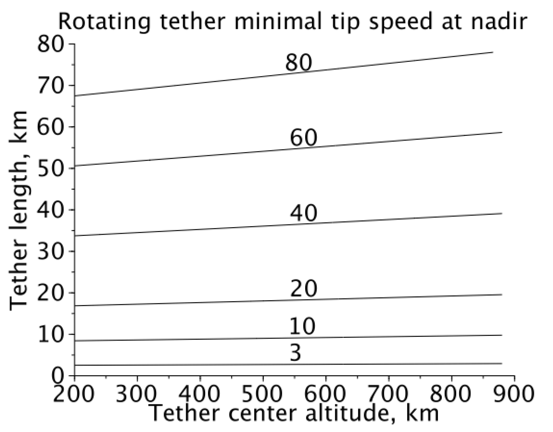
To calculate the rotating tether tip minimal speed at the nadir (or zenith) point, it is possible to equate the rotational energy of the tether at this point to the tidal energy of the tether stretched vertically (Equation (1a)). Equation (1a) states that to sustain rotation, the tether must have enough rotational energy to librate from a stable vertical orientation to an unstable horizontal orientation, with inertia of the tether acting against the tidal forces. Solving Equation (1a) with the gravity potential of Earth yields Equation (1b).


A plot of minimal initial tip speed of a hanging tether is shown in Figure 6.
In 2005, Pelaez [25] stated that a stationary solution for the tether tip argument in elliptic orbits does not exist, and a tether tip must librate as the gravity vector is rotating non-uniformly. Therefore, for elliptic orbits, the minimal rotation speed is reduced compared to circular orbits. This finding was also partially supported by a study of Takeuchi, the results of which were published in 2003 [18].
Figure 6.
The minimal nadir speed of the tether tip relative to the tether center of mass to sustain tether rotation.
Figure 6.
The minimal nadir speed of the tether tip relative to the tether center of mass to sustain tether rotation.
Micrometeoroids and orbital debris (MMOD) hazards play an important role in tether design.
The colliding objects frequency on LEO can be extracted from Figures 7–19 in [24] and approximated by Equation (2) for debris ranging from 4 µm to 2 cm in size. The collision probabilities are as summarized in Table 1.
Nyear = 1.6 ∙ 10-10D-2.56

| Particle size | Collision frequency for 1 m2 single-side target |
|---|---|
| 100 µm | 2.8 collisions/year |
| 200 µm | 0.48 collisions/year |
| 500 µm | 0.045 collisions/year |
| 1 mm | 0.0077 collisions/year |
| 2 mm | 0.0013 collisions/year |
| 2.5 mm | 0.00074 collisions/year |
| 3 mm | 0.00046 collisions/year |
Although, in 1995, Forward and Hoyt [26] claimed a redundancy of the fail-safe tether (hoytethers) may be implemented without sacrificing the tensile strength, it is highly unlikely, given the extreme difficulty of producing lightweight coupling to the fibers with high tensile strength. Couplings in damaged hoytethers would subject redundant filaments to the compressive stress. All high-strength fibers are weak in compression (with typical tensile-to-compression strength ratios being 10–40 [27]. Fatigue strength of filaments may be degraded as well, because zones of compression are a likely place for cracks to nucleate. Therefore, contrary to the conclusion of Forward and Hoyt [26], the failures of individual filaments in single hoytether segments may be correlated. As such, stated increases of redundant tether (hoytether) lifetimes may be not achievable, although further experiments are necessary to validate or reject such a claim.
An alternative, an advanced form of a Whipple shield (stopping 6.3 mm particles for 10.8 kg/m2 weight already flown [28]) may be better suitable for higher-diameter tethers. The stuffed Whipple shield (multishock shield) model with multiple layers spaced by 1.8 mm and a weight of 0.4 kg/m2 per layer was integrated into software used to generate the sample mission budgets in Section 6.
3. The Inconvenience of the Tip Masses or Counterweights
This Section is intended to outline the conditions when the momentum transfer tether with tip mass or counterweight may be useful. In addition, the related problem of matching rotation phase of the bolo with the payload trajectory will be discussed with a resulting conclusion on the inconvenience of tip masses or counterweights for launch-assist missions using LEO bolos.
In 2001, Ruiz [29] proposed to use momentum-transfer tethers for orbit apogee raising. Ruiz [29] found that additional tip mass raises the transfer orbit apogee, but no tether reuse, spin-up, or catch requirements were considered.
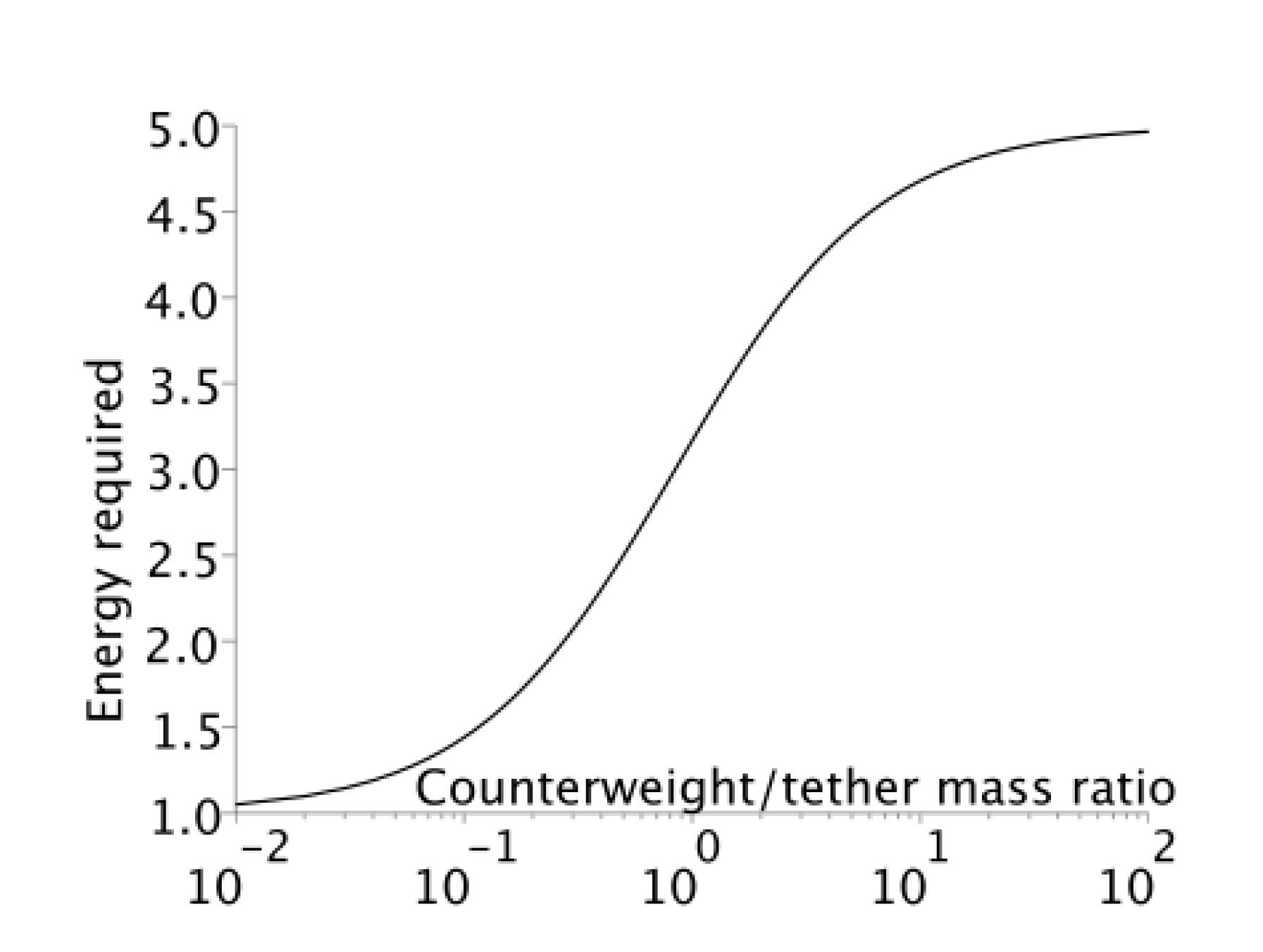
The bolo must not only be deployed to LEO, but also rotated to its operational tip velocity if aero-spinning alone cannot be relied upon. Such a spin-up requirement is non-trivial, and requires, most realistically, a hydrazine-powered (or electric-ion) low-thrust rocket pod on either end of the tether. Therefore, minimization of the energy required for spin-up will allow reduction of bolo launch mass. Such minimization of energy spent generally requires minimization of the moment of inertia of the entire bolo. Therefore, placement of any massive components on the bolo tip (as counterweight) will result in larger energy requirements for bolo spin-up, as illustrated in Figure 7. Any energy spent for bolo spin-up is lost for momentum transfer because payload is only subject to radial acceleration by the bolo.
Figure 7.
The energy (normalized) spent to spin-up a tether with a point-mass counterweight on one end, from standstill to fixed free tip velocity.
Figure 7.
The energy (normalized) spent to spin-up a tether with a point-mass counterweight on one end, from standstill to fixed free tip velocity.

In addition, it is advisable to reduce the bolo moment of inertia to allow easy adjustment of the rotation phase. Such an adjustment is necessary to catch payloads launched from the fixed Earth’s location to the lowest point of tether.
Relying on a booster rocket to provide cross-time to meet the bolo tip in its lower point will result in the booster flying long segments in non-ballistic trajectory, with resulting delta-v losses of 400–800 m/s.
The phase of the bolo can be adjusted either by tip rockets (very expensive, in terms of propellant mass and added weight) or by reeling/unreeling the tether to the central hub. In 2006, Williams [30] devised a method to change the spin rate of the rotovator (bolo) using Coriolis forces on the tether in a yo-yo configuration, without any reaction thrusters. The reeling/unreeling mechanism provides necessary cross-time capability for 1–10 W power levels (250 kg payload designs in Section 6) and reel speed below 1 mm/s. Maximal reeled length is 100 m for 43 s cross-time compensation within a two-day reeling maneuver. In 1998, Tragesser [31] also proposed adjusting the aerodynamic drag of the tether with planetary atmosphere during flyby, by means of winding/unwinding the tether.
Given the lesser role of aerospinning (described in Section 2) at altitudes above 300 km and the necessity to minimize the moment of inertia of bolo, the optimal bolo configuration would be the symmetric tether with powered spacecraft for bolo re-boost placed at or near the tether center. Counterweight may still be considered if heavy MMOD protection or the reduction of aero-spinning spin-up rate (for very low orbits) is important.
4. Tether Materials
This Section links the momentum transfer tether system architecture and environment discussion in Section 1, Section 2 and Section 3 with the mission design in Section 6 by providing guidelines as well as examples to the calculation of the physical properties of the tethers. In particular, tether strength and maintenance are discussed.
The primary component of the bolo is the high-tension rope (tether), characterized by the critical tip velocity, dependent on strength to weight ratio. In 2001, Ziegler [32] calculated an equation for the maximal permissible rotation speed (or maximal payload for given rotation speed) of tether with a payload attached to one end (See Equation (3a,b)).


However, using only ultimate tensile strength and density of material to calculate breaking force may lead to over-optimistic calculations of critical tip velocity and tether mass, as happened to Jokic [33], as the strength of the tether (rope) is mostly a function of defects present in tether material, not the material. For example, although the highest reported measured strength of microscopic alumina fibers was 22.3 GPa [34], the same material from the same manufacturer has a strength of 6.7 GPa [27] if made into long (0.5 m) fibers. Such a decrease of strength is a combination of the effect of the easy slip planes, surface imperfections, and voids inside the alumina fibers. In 2002, Elises [27] published a detailed review of high-strength fibers and their failure modes, and any tethered-mission designer is strongly advised to read it.
The following derating from the ultimate tensile strength should be used:
- (1)
- If loads are periodic or constant (as opposed to impulsive), use maximal yield strength;
- (2)
- If brittle failure is possible in metal elements by a factor of 3 [27];
- (3)
- For time-dependent degradation (especially for Zylon);
- (4)
- For a maximal operating temperature (or up-rate, if operating temperature is low);
- (5)
- For ultraviolet light and radiation-induced degradation;
- (6)
- For the bundling of yarn (not all yarns are tensioned equally)—this penalty increases with tether diameter;
- (7)
- For the weaving of rope (bundles are twisted and pre-stressed);
- (8)
- For atomic oxygen erosion (for tethers on LEO) or decomposition catalysts present (copper on polyethylene);
- (9)
- For the creep during service life (most important for polymer ropes, especially UHMWPE) [35];
- (10)
- For the extra length of the tether compared to length of test specimens (variability of strength increases logarithmically with an increase in sample length).
All derating coefficients may be cumulative.
Typically, after all deratings, loading all of the potential tether materials beyond 30% of their respective ultimate tensile strength is dangerous, and some synthetic fibers (UHMWPE, polyester, Kevlar in marine environments) may be usable only up to 5%–20% of their ultimate tensile strength [27].
One is sometimes misled by the stated structural factors of 1.5 to 2.0 (corresponding to loads 67% to 50% of ultimate tensile strength) of the structural components (wings, for example) of aircraft. Such low structural factors are possible only if component is available for defectoscopy or is flying a very short time. The impressive reliability of modern aircrafts is the function not only of advanced materials, but also of inspection infrastructure. If one cannot monitor (and as necessary, repair) small cracks or scars before they grow to a dangerous size, it is better to double the structural factors of component in question.
In addition, the geometry of the rotating tether is very unfavorable to timely crack detection, even if defectoscopy equipment is available during normal tether operation. Critical cracks may be only 1–2 mm long in steel fibers (necking and then brittle failure) and 10–20 mm long in UHMWPE ropes (creep, fibrillar, and then brittle failure).
For example, let us estimate usable 10 km tether strength for two materials: 2 GPa New Japan Steel wire for suspension bridge cable [36] and Dyneema SK78 0.54 mm multifilament UHMWPE yarn [35]. The comparison is provided in Table 2.
Due to the complex nature of derating, as much data as possible was derived from the actual testing of the ropes rather than from material specifications.
Overall, although UHMWPE provide 10× better average strength-to-weight ratio compared to steel filament, the performance of the UHMWPE is more derated because of strength variability, insufficient testing, and creep.
| Materials | Akashi bridge cable wire | Dyneeema SK78 multi-filament yarn |
|---|---|---|
| Ultimate tensile strength | 2.0 GPa | 2.34 GPa (for a fill factor of 0.78) |
| Diameter | 5.23 mm | 0.54 mm × 10 |
| Effective density | 7700 kg/m3 | 756 kg/m3 (for a fill factor of 0.78) |
| Length to implement | 10 km | 10 km |
| (1) Yield derating | IIMD * | IIMD * |
| (2) Brittleness derating | 0% (below fatigue limit) | 0% (below creep limit) |
| (3) Degradation derating | IIMD * | n/a |
| (4) Temperature derating | IIMD * | IIMD * |
| (5) Radiation derating | 0% (steel is radiation hard) | 30% (estimated) |
| (6) Bundling derating | n/a (single wire) | IIMD * for 0.54 mm, 12% for 5.4 mm |
| (7) Weaving derating | n/a (single wire) | IIMD * |
| (8) Erosion derating | 0.0007%/year (274 km orbit) | 0.26%/year (274 km orbit) |
| (9) Creep derating | IIMD * | IIMD * for 1 year lifetime (−70%) # |
| (10) Length derating | 0% (tested in 2 km pieces) | −70% (7% strength variability in 0.5 m test samples up-rated to 10 km length) |
| Total IIMD * derating | −68.75% | 70% |
| Total derating (1 year) | −68.75% | 81.6% |
| 1/(Structural factor) | IIMD * | 33.3% |
| Usable tether strength | 625 MPa & | 287 MPa |
| Derated tip velocity | 284 m/s | 616 m/s |
| Tether usable strength | 13.4 kH | 15.0 kH |
# If length derating exceeds creep derating, it is safe to apply creep derating only; * Included in manufacturer data; & Similar stress was applied to steel hanging wires at the Pylons of Messina (608 MPa at 3.6 km span).
Tapered tethers, although theoretically more mass-effective, were not considered. Although the tapered fibers are known to naturally occur in sea urchins and sea cucumbers, which condones the superior strength of their ligaments, as noted in 2000 by Trotter [37], engineering processes for the manufacturing of tapered fibers or ropes is absent. The only available option to imitate a tapered tether is hence a connection of the ropes of different thicknesses through the adapter. Such adapters impose additional weight and reliability penalties; therefore, adapters are practical only for large tapering ratios.
5. The Challenge of the Bolo Rendezvous and Catching
This Section defines the interface between highly speculative momentum transfer architecture and hardware outlined in Section 1, Section 2, Section 3 and Section 4 and existing rocket propulsion hardware. A literature review on payload capture and tentative overview of hardware components for payload capture will be provided in this section.
Catch of payload by LEO bolo has very strict requirements for speed, location, and time-matching between the payload and bolo tip. A space-docking experience is not applicable for rendezvous with momentum transfer tethers. In 2006, Williams [38] investigated the low-speed tether capture dynamic. A conclusion was that, to avoid transient loads, the capture time must be at least two orbital revolutions—an unsuitably long interval for bolo tip capture. For high-speed rendezvous, an asteroid grapple was proposed in 2000 by Lanoix [39] for a tethered swing-by of the asteroids to modify the spacecraft’s speed vector. Such an approach is intrinsically unreliable and far beyond the capability of the existing throwing grapples.
Historically, most resembling the bolo capture was the air recovery of Corona satellites, Stardust sample recovery, or attempted recovery of the Genesis sample capsule. A satellite being recovered closely resembles the bolo tip, while recovery aircraft mostly resemble the suborbital, maneuvering payload. The Corona satellite was captured at high relative velocities (up to 60 m/s) using a combination of hooks hanging from aircrafts and loops created by parachute ropes attached to the Corona satellite. It is a flight-proven solution.
Research is currently in progress, specifically for bolo by Newton [40] at the Tennessee Tech University, but only on room-scale, open-loop models. The grappling aperture of Newton [40] is heavy, weighing 10% of the payload mass. Furthermore, a capture happens at zero relative velocity—a feature requiring multi-second speed adjustment phase in the actual flown, close-loop controlled payload. The speeds of the bolo tip and payload cannot be matched far away from the rendezvous point because of the natural uncertainties of the payload trajectory. Most of the uncertainty happens due to interaction with winds, turbulence, unsteady rocket engine thrust, fuel slosh, and rocket stage pointing errors. It is common for the last stage of the orbital vehicle to be left within ~10 m/s of the desired speed, even if bi-propellant liquid-fuel engines are used. Solid-fuel engines have an even worse final speed spread (Pegasus XL official 3-sigma error is 150 m/s [41]). Therefore, a multiple correction maneuvers must occur at the last moments, guided most likely by bolo tip radio beacon, GPS, and laser rangefinder. Even as such, intervals of a few seconds of the bolo tip and payload at low relative speed (<30 m/s) are desirable to roughly adjust range and orientation errors, given the typical low agility of the modern orbital boosters.
Requirements for the orbital booster (or payload only) to have an increased agility in order to be caught will surely result in payload-bearing modules having too much deadweight, out-weighing any benefit from any ∆v savings provided by the bolo.
Given these constraints, the only currently achievable flight profile leading to successful bolo rendezvous is reuse of the main engine in the last stage of the orbital booster to roughly match the acceleration of the bolo tip for a few seconds before the catch moment.
Typical upper stages have linear accelerations up to 30 m/s2, throttleable down to 60% of nominal thrust, and have angular accelerations up to 4 rad/s2 (typical for Falcon-1e upper stage). To equalize longitudinal and transverse agility, these parameters result in free acceleration of 6 m/s2 with acceleration lagging about 0.2 s after controls. An approximate correctable course deviation as a function of the rendezvous window duration can be approximated as Equation (4):
![Aerospace 01 00031 i005]()

If Ncorrections =4, tlag =0.2 s, amax − amin =12 m/s2, trendezvous =3 s, the correctable trajectory error is 15 m, which is within the error margin provided by the commercial GPS. But the same trajectory correction maneuver will cost the upper stage a ∆v proportional to the rendezvous window duration, which is expressed as Equation (5).

Such a ∆v loss for terminal guidance would be in the order of 100 m/s for the typical upper-stages and a rendezvous window duration of 3 s.
Payloads with attachment hardware must be designed to disconnect from last stage immediately on successful attachment with the tether tip, and at the same moment the last-stage engine must start the shutdown to prevent re-contact with the payload. Engine shutdown speed requirements are expected to be less severe compared to normal stage separation due to the payload acceleration provided by the tether.
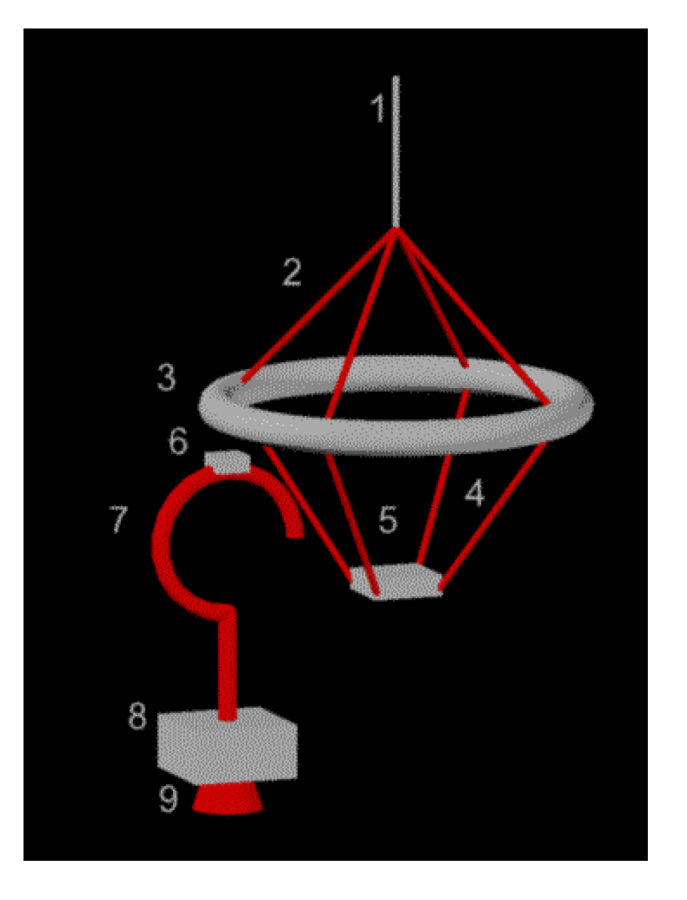
In Figure 8, a tentative concept of payload capture-associated hardware for LEO bolo is shown. The concept is derived from the Corona satellite recovery scheme and explained in detail below.
Figure 8.
A tentative hook-and-loop catch mechanism for LEO bolos. (1) tether; (2) stiffening rods; (3) load redistribution ring; (4) shock absorbing ropes; (5) saddle for hook; (6) hook release (pyrotechnic-actuated hinge); (7) payload hook; (8) payload; (9) payload adapter to rocket last stage.
Figure 8.
A tentative hook-and-loop catch mechanism for LEO bolos. (1) tether; (2) stiffening rods; (3) load redistribution ring; (4) shock absorbing ropes; (5) saddle for hook; (6) hook release (pyrotechnic-actuated hinge); (7) payload hook; (8) payload; (9) payload adapter to rocket last stage.

Tether design (1) is covered in Section 4 of this paper. The most optimal construction of stiffening rods (2) and load redistribution rings (3) is high-stiffness Li-Al alloy pipes. Given the ultimate tensile strength of such constructs 550 MPa, with a structural factor of 8 (typical for shock-loaded structures) and ring diameter of 3 m, parts (2) and (3) matching the strength of tether calculated in Table 2, can be constructed of 15 m Li-Al pipes weighing 7 kg in total. The most suitable material for shock absorbing ropes (4) is polyester, widely used for similar roles in rock climbing. Using the same analogy as rock climbing, the saddle (5) should be made of high-toughness steel, totaling 5 kg for (4) and (5) by up-scaling normal rock climbing gear to the loads in Table 3. The pyrotechnic bolt (6) or other actuator is necessary to provide a rapid payload release, and must have a weight below 0.5 kg. The 3-m-long payload hook (7) is the most weight-critical component because it must be launched with each payload, and also requires increased payload fairing size. Although the hook itself will be about 2 kg (less than 1% of payload mass as calculated in Section 6), the added weight and size of fairing may increase gravity loss and air drag ∆v requirements. Therefore, such a hook system strongly favors booster design without the need of fairing. Such designs were proposed in 2012 by Nizhnik [42]. The payload (8) must be strengthened to accommodate additional stress of tether catch, but because in the proposed configuration, the main shock is aligned with normal rocket booster thrust vector, payload weight penalty is likely going to be negligible. The payload adapter (9) of the Ariane-5 rocket, as described in [43], is completely adequate for the tether catch operation. Therefore, no further development is necessary on payload adapter.
| Mode | Existing steel tether | Existing PE tether | 10 W/kg hub and PE | Double-strength PE |
|---|---|---|---|---|
| Catch mass | 246 kg | 247 kg | 247 kg | 243 kg |
| Tether rotation period | 52 s | 73 s. | 73 s | 152 s |
| Tether length | 4 km | 9 km | 9 km | 32 km |
| Tether tip speed | 242 m/s | 387 m/s | 387 m/s | 661 m/s |
| Tether tip acceleration | 29.2 m/s2 | 33.3 m/s2 | 33.3 m/s2 | 27.3 m/s2 |
| Tether tension without payload | 6.2 kH | 6.8 kH | 6.8 kH | 23.3 kH |
| Tether tension with payload | 13.4 kH | 15 kH | 15 kH | 30 kH |
| ∆v for payload | 474 m/s | 759 m/s | 691 m/s | 1310 m/s |
| ∆v for tether & | 13.8 m/s | 16.4 m/s | 88.7 m/s | 15.3 m/s |
| Tether mass (with shield) | 852 kg | 810 kg | 810 kg | 3416 kg |
| Tether MMOD shield weight | 190 kg | 651 kg | 651 kg | 3257 kg |
| Tether MMOD shield blocking class | 2 mm | 2.5 mm | 2.5 mm | 3 mm |
| Tether effective drag area | 20.6 m2 | 56.7 m2 | 56.7 m2 | 238 m2 |
| Total effective drag area (night glider mode) | 30.3 m2 | 70.3 m2 | 70.1 m2 | 260.5 m2 |
| Tether hub power | 7.6 kW | 10.7 kW | 11.2 kW | 17.4 kW |
| Tether hub mass | 7.6 ton | 10.7 ton | 1.1 ton | 17.4 ton |
| Tether catch orbit, perigee × apogee (km) | 299 × 321 | 357 × 383 | 322 × 458 | 420 × 444 |
| Post-release (circular) tether orbit altitude | 299 km* | 357 km* | 322 km* | 420 km* |
| Pre-capture payload orbit, perigee × apogee (km) | 111 × 299 | −218 × 365 | −214 × 317 | −591 × 404 |
| Post-release payload orbit, perigee × apogee (km) | 301 × 487 | 375 × 958 | 327 × 858 | 448 × 1455 |
| Payload increase # | 25 kg | 42 kg | 34 kg | 79 kg |
| Base payload | 246 kg | 247 kg | 247 kg | 243 kg |
| Tether hub thrust for post-release orbit departure | 60 mH | 45 mH | 90 mH | 53 mH |
| Thrust necessary for tether 1 week-long re-boost | 193 mH | 311 mH | 283 mH | 527 mH |
| Refueling frequency, every Nth payload | N = 24 | N = 17 | N = 17 | N = 10 |
| Lifetime required to break-even mass on LEO | 10.89 years | 7.95 years | 1.91 years | 7.32 years |
| Average time to break due micrometeorites | 115 years | 97 years | 97 years | 44 years |
& Not taking into account terminal guidance ∆v loss (about 100 m/s); * Polar orbit was assumed for all cases; # Compared orbital delivery to 185 × 185 km parking orbit without momentum transfer tethers.
An alternative solution may be to spin a secondary tether around the tip of the primary tether, nullifying tether tip acceleration at the moment of capture and therefore allowing low-acceleration rendezvous. That solution was first proposed in 2004 by Williams [44], but a dedicated research program may be necessary to develop it.
6. Example Missions Designs
In this section, the conclusions on momentum transfer architecture (Section 1 and Section 3), environment (Section 2), tether hardware (Section 4), and tether interface (payload capture, Section 5) are combined in a coherent LEO constellation delivery mission. This mission is compared against a similar mission, which uses only chemical propulsion—namely, Falcon-1e vehicles. To avoid potentially misleading economic and payload utilization considerations, mission merit is determined as mass of hardware placed on at least a 185 km LEO orbit by using equal numbers of Falcon 1e launches. Fractional launches (part of the rocket-delivering part of the payload) are also considered possible for simplicity.
A software package was developed in the Scilab for the semi-automatic calculation of the mass budget of the space launch mission using momentum transfer tethers. The Scilab scripts are provided on request or available on the author’s page at www.researchgate.net. A total of nine scripts were used and briefly described below. The mission budgets derived from auto-budget script outputs are provided in Table 3.
The Tether_reentry.sce script works as follows:
- (a)
- The MSISE-90 atmospheric model is loaded and interpolated with a resolution of 1 km.
- (b)
- The distribution of atmospheric drag across the tether is calculated at five segments across the tether length for rotation angles with step 15 degrees.
- (c)
- The circular orbit altitude drop is calculated from energy and impulse conservation laws. Spacecraft assumed to collide inelastically with air molecules, therefore transferring the kinetic and potential energy of spacecraft to air, accelerating and ultimately heating it. The application of conservation laws is possible if the orbit decaying quasi-statically. Quasi-staticity mean drag acceleration several orders of magnitude below gravity acceleration, and gravity acceleration magnitude varying negligible per orbit. For this to happen, orbit must be near-circular and gravity field must be nearly-spherical. Real decaying low-earth orbits are slightly non-circular (orbital eccentricity is varying around 0.001 due non-spherical gravity fields). In addition, a few minutes before reentry, decay becomes not quasi-static due to increasing drag acceleration.
- (d)
- The time step is adapted to keep the orbit altitude drop rate in the 0.1–1 km/step range.
- (e)
- Simulation is terminated after the orbit is lowered to 100 km altitude.
- (f)
- The steps b–e are swept for various tether lengths and initial orbit altitudes. The tether rotation speed is derived from the Steady_tether_speed.sci script output.
The Steady_tether_speed.sci script works as follows:
- (a)
- The MSISE-90 atmospheric model is loaded and interpolated with a resolution of 1 km.
- (b)
- Initially assumed tip speed is 1 m/s and the speed adaptation coefficient is 1.4.
- (c)
- Torques arising from center of pressure and center of mass mismatch are calculated for nine tether segments and averaged over a rotation period with step 3 degrees.
- (d)
- If torque is found to be positive, estimated speed is multiplied by speed adaptation coefficient until torque becomes negative.
- (e)
- If torque is found to be negative, estimated speed is divided by speed adaptation coefficient until torque becomes positive.
- (f)
- When torque changes sign, the speed adaptation coefficient is set to the square root of itself.
- (g)
- The steps c–f are repeated until torque absolute value is reduced below the pre-determined accuracy.
- (h)
- The steps b–g are repeated while sweeping orbit altitude and tether mass.
The Tether_spinup_time.sci script works as follows:
- (a)
- The MSISE-90 atmospheric model is loaded and interpolated with a resolution of 1 km.
- (b)
- The output of Steady_tether_speed.sci is divided by torque calculated for zero rotation speed, but averaged for all possible tether orientations with step 3 degrees.
The tether_minspeed.sce script simply applies Equation (1) for the range of the tether lengths and circular orbit altitudes.
The tether_mmod.sce script calculates the total weight of MMOD shield for a given length and diameter of tether, using tabulated MMOD shield area density extracted from [28].
The tether.sce script uses laws of energy and momentum conservation to calculate the following parameters as a function of payload weight to tether weight ratio:
- (a)
- The ∆v imparted on the tether as a result of payload capture and release.
- (b)
- The ∆v imparted on the payload after being carried by the tether from a capture point directly below the tether hub to a release point directly above the tether hub.
The auto-budget scripts, (Tether_autobudget_UHMWPE.sce and Tether_autobudgetSteel.sce), do automatically calculate power and propellant requirements for the catch-release-reboost momentum transfer cycle, given average orbit altitude and launch frequency. Optimization of these is left for the user. Other script outputs are used as input for auto-budget scripts. Average altitude of the tether capture orbit was swept to minimize orbital mass break-even time. Break-even time is the interval necessary for the bolo system to transfer, to orbit, additional (compared to purely rocket system) mass equal to the initial bolo weight (plus all ion motor fuel spent in the process). It was discovered that higher launch rates result in the reduction of orbital break-even time, up to a launch frequency of 180 per year. It was also found that a launch frequency above 52 launches/year (weekly) results in a bolo system that is undeliverable to orbit by medium-lift vehicles. Therefore, only bolo capture orbit average altitude was optimized, while launch frequency was fixed to 52 launches/year. For more robust optimization convergence, the gravity gradient on LEO was linearized. Therefore, all apogee and perigee data in Table 3 are approximations only. The tether strength data was derived from the Table 2. Typical satellite power density (1 W/kg) and solar panel energy output (150 W/m2) were used for columns 1, 2, and 4. Solar panels are assumed to have an effective drag factor of 1 in sunlight and 0.2 in shadow, corresponding to the “night glider” operation mode.
The payload catch is assumed to happen near the perigee of the bolo orbit to avoid perigee lowering and excessive air drag during re-boost. The payload is released after a half-rotation of the bolo, still near the bolo perigee, to maximize momentum transfer (in line with [45]). After payload release, the tether orbit is considered circularized.
In 2006, Ahedo [46] explained how any conductivity of the tether on Earth’s orbit will result in electromagnetic force, causing eventual tether de-orbit. Therefore, only insulating or semi-insulating tethers (with insulator junctions between segments) can be considered for long-term, low-loss operation. However, for sake of simplicity, that effect for steel (hence, conductive) tethers was not taken into account.
Surprisingly, the concept that the re-boost engine specific impulse is a limiting factor, as stated in 2003 by Sorensen [10], was proven wrong, as fuel spent for currently existing ion motors (1500 s ISP and 50% efficiency) was found to reduce tether-assisted payload increase for about 1/4 only. This conclusion is in line with analysis by Sanmartin [47], who rejected magnetic-reboosted (MXER) tethers. Sanmartin [47] states that a tether-magnetic system will be too heavy, compared to the electric propulsion, if orbital transfer times below one month are required due to poorer power efficiency and associated weight of the necessary photovoltaic panels.
In addition, a small role of the material strength was found. Although bolo performance (pay-off time) moderately improves (by 27%) if steel tether is replaced for available high-strength UHMWPE rope (five times stronger for same weight), further doubling of tether strength results only in a 9% improvement in pay-off time. The main reason for such a performance stagnation is the limiting role of the payload catch specifications. If acceleration at the tether tip is kept at 30 m/s2, as advocated in Section 5, a faster tether tip speed results in an increase of tether length, with an associated increase of the MMOD shield weight. In addition, high-speed bolos tend to be most efficient at higher altitudes because of a large drag-to-mass ratio. Therefore, although ∆v delivered may be impressive (1.31 km for double-strength UHMWPE rope), most of the delivered ∆v is over the ∆v required for LEO orbit insertion. It must be stressed that all ∆v beyond minimal-altitude (185 km approximately) circular LEO delivered by bolo system is simpler (and cheaper) to deliver using onboard ion motors or inter-orbital ion tug, for example, the ion tug designed by Jaffe [48] or Hermel [49]. Ion tug will clearly be more efficient in the absence of the heavy, damage-prone tether. In 1972 and 1975, Mason [50] and Strauss [51], respectively, questioned the usefulness of the ion tugs compared to expendable chemical propulsion. Absence of the ion tugs, as recently as 2013, has proven their statement.
However, power density of the bolo hub spacecraft was found to be very important, with 4.16 times the break-even time reduction if power density rises from 1 W/kg to 10 W/kg. In addition, although total ∆v delivered to payload is reduced because of the lower bolo mass, ∆v to reach catch point is actually decreased because of the bolo lower optimal orbit altitude. The entire ∆v penalty for the light (high power-density) hub is, thus, applied for reduction of the apogee of the post-release orbit. The result is more circular post-release orbits compared to missions using standard power density spacecrafts. These orbits are well-matching the launch-assistance purpose of the LEO bolo, outlined in Section 1
7. Conclusions
This section summarizes the factors critical for the efficacy of the LEO launch assistance mission using LEO bolos, calculated in Section 6. Five directions for making such missions feasible are outlined, with most promising direction being the increase of spacecraft power/weight ratio.
The development of a hypothetical space mission involving a satellite constellation delivered to orbit with the help of a LEO bolo has resulted in the following conclusions:
Specific impulse (~1500 s) of modern ion motors is sufficient to deliver a 3:1 reduction of fuel mass spent for bolo-assisted momentum transfer (compared to chemical rockets). Development of MXER tethers is not critical for the momentum-transfer applications, unless tethers with tip speeds approaching 1 km/s will be deployed.
Long-term strength of existing ropes is sufficient for LEO bolos. Tether maintenance crawler(s) may offer significant reduction of tether strength margin(s), but increasing tether strength does not significantly improve system performance, due to the added weight of the tether re-boost hardware and micrometeoroid shield.
The power density of modern spacecrafts (1 W/kg) is inadequate for LEO bolos deployment. Development of higher power-density (up to 10 W of electrical power per kg) spacecrafts is necessary if realistic (~1–40 launches/year) launch rates are expected. Otherwise, launch rates of 50–200 launches/year are required to pay-off the initial cost of LEO bolo deployment (even if not taking into account R&D costs).
The power-to-drag of modern solar arrays in “night glider” mode is inadequate for bolos operating below a 300 km altitude. Better power efficiency of solar cells or solar panels operating in “sun slicer” mode are desirable. However, operating in “sun slicer” mode still requires many advances in large structures and energy storage. A nuclear powered bolo for a 240–280 km catch orbit may be considered if politically acceptable.
Plain tethers are vulnerable to micrometeoroid damage. Either shielded or redundant tethers must be used. Currently, shielded tethers seem to be the most developed solution, and are weight-effective for tethers below 10 km long.
Payload capture requirements strongly favor high-agility upper stages of rocket boosters to reduce terminal guidance ∆v loss.
Acknowledgments
This work was partially supported by Japan Science and Technology Agency within the ERATO (Exploratory Research for Advanced Technology) project.
Conflicts of Interest
The author declares no conflict of interest.
References
- Frisbee, R.H. Advanced space propulsion for the 21st century. AIAA J. Propuls. Power 2003, 19, 1129–1154. [Google Scholar] [CrossRef]
- Powell, J.; Maise, G.; Rather, J. Maglev Launch: Ultra Low Cost Ultra/High Volume Access to Space for Cargo and Humans. Available online: http://www.startram.com/resources (accessed on 17 December 2013).
- Gates, S.S.; Koss, S.M.; Zedd, M.F. Advanced tether experiment deployment failure. AIAA J. Spacecr. Rocket. 2001, 38, 60–68. [Google Scholar] [CrossRef]
- Kruijff, M.; van der Heide, E.J. Data analysis of a tethered SpaceMail experiment. AIAA J. Spacecr. Rocket. 2009, 46, 1272–1287. [Google Scholar] [CrossRef]
- Tethers in Space. AIAA Aerospace America Magazine, December 2010; 59–64.
- Lorenzini, E.C.; Bortolami, S.B. Control and flight performance of tethered satellite small expendable deployment system-II. AIAA J. Guid. Control Dyn. 1996, 19, 1148–1156. [Google Scholar] [CrossRef]
- Menon, C. Design and testing of a space mechanism for tether deployment. AIAA J. Spacecr. Rocket. 2007, 44, 927–939. [Google Scholar] [CrossRef]
- Wiesel, W.E. Optimal payload lifting with tethers. AIAA J. Guid. 1988, 11, 352–356. [Google Scholar] [CrossRef]
- Hoyt, R.P. Responsive a Launch of Small Spacecraft Using Reusable in-Space Tether and Air-Launch Technologies. Available online: http://www.tethers.com/papers/MXERSpace2006Paper.pdf (accessed on 18 December 2013).
- Sorensen, K. Momentum Exchange Electrodynamic Reboost (MXER) Tether Technology Assessment Group Final Report. 2003. Available online: http://www.nasaspaceflight.com/_docs/MXER%20TAG%202003%20Report.pdf (accessed on 18 December 2013).
- Williams, P. Tether capture and momentum exchange from hyperbolic orbits. AIAA J. Spacecr. Rockets 2010, 47, 205–209. [Google Scholar] [CrossRef]
- Hoyt, R.P. Cislunar tether transport system. J. Spacecr. Rocket. 2000, 37, 177–186. [Google Scholar] [CrossRef]
- Luo, A.C.J.; Han, R.P.S.; Tyc, G. Analytical vibration and resonant motion of a stretched spinning nonlinear tether. AIAA J. Guid. Control Dyn. 1996, 19, 1162–1171. [Google Scholar] [CrossRef]
- Puig-Suari, J.; Longuski, J.M.; Tragesser, S.G. Aerocapture with a flexible tether. AIAA J. Guid. Control Dyn. 1995, 18, 1305–1312. [Google Scholar] [CrossRef]
- Tyc, G. Attitude dynamics investigation of the OEDIPUS-A tethered rocket payload. AIAA J. Spacecr. Rocket. 1995, 32, 133–141. [Google Scholar] [CrossRef]
- Vigneron, F.R.; Jablonsky, A.M.; Chandrashaker, R. Comparison of analytical modeling of OEDIPUS tethers with data from tether laboratory. AIAA J. Guid. Control Dyn. 1997, 20, 471–478. [Google Scholar] [CrossRef]
- De Matteis, G.; de Socio, L.M. Dynamics of a tethered satellite subjected to aerodynamic forces. AIAA J. Guid. 1991, 14, 1129–1135. [Google Scholar] [CrossRef]
- Takeuchi, N.; Natori, M.C.; Okuizumi, N. Fundamental strategies for control of a tethered system in elliptical orbits. AIAA J. Spacecr. Rocket. 2003, 40, 119–125. [Google Scholar] [CrossRef]
- Martinez-Sanchez, M.; Gavit, S.A. Orbital modifications using forced tether-length variations. AIAA J. Guid. 1987, 10, 233–241. [Google Scholar] [CrossRef]
- Phillips, W.H. Theoretical Analysis of the Oscillation of a Towed Cable. Available online: http://naca.central.cranfield.ac.uk/reports/1949/naca-tn-1796.pdf (accessed on 18 December 2013).
- Stevens, G.W.H. A theory of vibrations in parachutes. AIAA J. Aircr. 1972, 9, 74–78. [Google Scholar] [CrossRef]
- Jokic, M.D.; Daniel, W.J.T. Aerogravity-assist maneuvering of a tethered satellite system. AIAA J. Spacecr. Rocket. 2004, 41, 614–621. [Google Scholar] [CrossRef]
- Piug-Suari, J. Optimal mass flexible tethers for aerobracking maneuvers. AIAA J. Guid. Control Dyn. 1997, 20, 1018–1024. [Google Scholar] [CrossRef]
- Wertz, J.R.; Everett, D.F.; Puschell, J.J. Space Mission Engineering: The New SMAD; Microcosm Press: Portland, OR, USA, 2011. [Google Scholar]
- Pelaez, J.; Andres, Y.N. Dynamic stability of elecrodynamic tethers in inclined elliptical orbits. AIAA J. Guid. Control Dyn. 2005, 28, 611–622. [Google Scholar] [CrossRef]
- Forward, R.L.; Hoyt, R.P. Failsafe Multiline Hoytether Lifetimes. In Proceedings of the 31st AIAA/ASME/SAE/ASEE Joint Propulsion Conference and Exhibit, San Diego, CA, USA, 10–12 July 1995. AIAA Paper 95–28903.
- Fiber Fracture; Elises, M.; Llorca, J. (Eds.) Elsevier: Oxford, UK, 2002.
- Dye, S. MMOD-IMLI: Thermal Insulation and Micrometeoroid/Orbital Debris Protection. NASA SBIR/STTR Technologies, SBIR Phase I Proposal. Available online: http://ehb8.gsfc.nasa.gov/sbir/docs/public/recent_elections/SBIR_10_P1/SBIR_10_P1_104617/briefchart.pdf (accessed on 16 April 2013).
- Ruiz, M.; Pelaez, J. Influence of a small end mass on tether-mediated orbital injection. AIAA J. Guid. Control Dyn. 2001, 24, 1108–1117. [Google Scholar] [CrossRef]
- Williams, P. Optimal deployment/retrival of a tethered formation spinning in the orbital plane. AIAA J. Spacecr. Rocket. 2006, 43, 638–650. [Google Scholar] [CrossRef]
- Tragesser, S.G.; Longuski, J.M. Analysis and design of aerocapture tether with accounting for stochastic errors. AIAA J. Spacecr. Rocket. 1998, 35, 683–689. [Google Scholar] [CrossRef]
- Ziegler, S.W.; Cartmell, M.P. Using motorized tethers for payload orbital transfer. AIAA J. Spacecr. Rocket. 2001, 38, 905–914. [Google Scholar]
- Jokic, M.D.; Longuski, J.M. Design of tether sling for human transportation systems between earth and mars. AIAA J. Spacecr. Rocket. 2004, 41, 1010–1015. [Google Scholar] [CrossRef] [Green Version]
- Soltis, P.J. Anisotropy of the tensile properties of submicron-size sapphire (Al2O3) whiskers. Bull. Am. Phys. Soc. 1965, 10, 163. [Google Scholar]
- Chimisso, F.E.G. Some Experimental Results Regarding Creep Behavior on Synthetic Materials Used to Produce Offshore Morring Ropes; Mechanics of Solids: Rio Grande, Brazil, 2009. [Google Scholar]
- Honshu-Shikoku Bridge Expressway Company Limited, 2013. Available online: http://www.jb-honshi.co.jp/technology/material.html (accessed on 13 December 2013).
- Trotter, J.A.; Tipper, J.; Lyons-Levy, G.; Chino, K.; Heuer, A.H.; Liu, Z.; Mrksich, M.; Hodneland, C.; Dillmore, W.S.; Koob, T.J.; et al. Towards a fibrous composite with dynamically controlled stiffness: Lessons from echinoderms. Trans. Biochem. Soc. 2000, 28, 357–362. [Google Scholar] [CrossRef]
- Williams, P. In-plane payload capture with an elastic tether. AIAA J. Guid. Control Dyn. 2006, 29, 810–821. [Google Scholar] [CrossRef]
- Lanoix, E.L.M.; Misra, A.K. Near-earth asteroid missions using tether sling shot assist. AIAAJ. Spacecr. Rocket. 2000, 37, 475–480. [Google Scholar] [CrossRef]
- Newton, K. NASA Engineers, Tennessee College Students Successfully Demonstrate Catch Mechanism for Future Space Tether. Available online: http://www.nasa.gov/centers/marshall/news/news/releases/2005/05–108.html (accessed on 15 April 2013).
- Isakowitz, S.J.; Hopkins, J.B.; Hopkins, J.B., Jr. International Reference Guide to Space Launch Systems, 4th ed.; AIAA: Reston, VA, USA, 2004; p. 295. [Google Scholar]
- Nizhnik, O. A low-cost launch assistance system for orbital launch vehicles. Int. J. Aerosp. Eng. 2012, 2012, 1–10. [Google Scholar] [CrossRef]
- Fortesque, P.; Swinerd, G.; Stark, J. Spacecraft Systems Engineering, 4th ed.; Wiley: Hoboken, NJ, USA, 2011; p. 254. [Google Scholar]
- Williams, P.; Blanksby, C. Prolonged payload rendezvous using a tether actuator mass. AIAA J. Spacecr. Rocket. 2004, 41, 889–893. [Google Scholar] [CrossRef]
- Kyroudis, G.A. Advantages of tether release of satellites from elliptic orbits. AIAA J. Guid. 1988, 11, 441–448. [Google Scholar] [CrossRef]
- Ahedo, E.; Sanmartin, J.R. Analysis of bare-tether systems for deorbiting low-earth-orbit satellites. AIAA J. Spacecr. Rocket. 2002, 39, 198–205. [Google Scholar] [CrossRef]
- Sanmartin, J.R. Efficiency of electrodynamic tether thrusters. AIAA J. Spacecr. Rocket. 2006, 43, 659–666. [Google Scholar] [CrossRef]
- Jaffe, L.D. Nuclear-electric reusable orbital transfer vehicle. AIAA J. Spacecr. Rocket. 1988, 25, 375–381. [Google Scholar] [CrossRef]
- Hermel, J.; Meese, R.A.; Rogers, W.P.; Kushida, R.O.; Beattie, J.R.; Hyman, J. Modular, ion-propelled, orbit-transfer vehicle. AIAA J. Spacecr. Rocket. 1988, 25, 368–374. [Google Scholar] [CrossRef]
- Mason, J.D. Space tug performance optimization. AIAA J. Spacecr. 1972, 9, 491–492. [Google Scholar] [CrossRef]
- Strauss, E.L. Ablative thermal protection for space tug multipass and aerobraking entry. AIAA J. Spacecr. Rocket. 1975, 12, 346–350. [Google Scholar] [CrossRef]
© 2013 by the authors; licensee MDPI, Basel, Switzerland. This article is an open access article distributed under the terms and conditions of the Creative Commons Attribution license (http://creativecommons.org/licenses/by/3.0/).
Share and Cite
MDPI and ACS Style
Nizhnik, O. The Space Mission Design Example Using LEO Bolos. Aerospace 2014, 1, 31-51. https://doi.org/10.3390/aerospace1010031
AMA Style
Nizhnik O. The Space Mission Design Example Using LEO Bolos. Aerospace. 2014; 1(1):31-51. https://doi.org/10.3390/aerospace1010031
Chicago/Turabian StyleNizhnik, Oleg. 2014. "The Space Mission Design Example Using LEO Bolos" Aerospace 1, no. 1: 31-51. https://doi.org/10.3390/aerospace1010031