3.1. Intermediate-Scale Fire
A free pool-like fire is stabilized on a horizontal rectangular porous burner [
17] with a 0.25 m long (
x) by 0.4 m wide (
y) slot with a heat release rate of 36 kW. It is important to understand what characteristic length scale, which is related to the heat release rate (HRR), must be resolved. In general, the large-scale structure that is controlled by the inviscid terms can be completely described when the characteristic length is spanned by roughly ten computational cells [
16]. For the fire plume considered here, the characteristic length is in an order of 0.25 m. This implies that adequate resolution of the fire plume at a large scale can be achieved with a spatial resolution of about 0.025 m in a 3D computational domain of 1.5(
x) × 1(
y) × 2(
z) m
3. Based on this spatial reference value, the grid was locally refined in the fire region where a strongly stratified layer is developed. In the first case, the calculations were performed using a computational mesh with 62 cells in the direction
x, 50 cells across (
y) and 82 cells in the vertical direction (
z). Along the axis x, start at 0.01 m in the combustion zone, and stretch to about 0.05 m at the free boundary. In the vertical direction, z, cell sizes are about 0.008 m around the burning zone and stretch to about 0.06 m at the free boundary. A uniform grid is used with a cell size of about 0.008 m in the y direction. Grid refinement studies were performed for checking the influence of the number of grid cells on the predicted results. In the second case, the number of grids with 82(
x) × 60(
y) × 102(
z) was used (about 1.5-times as fine) with the extra grid points being added in regions of high velocity or temperature gradients. A further reduction in the grid size results in a large computational overhead due to a significant reduction in the time step (Δ
t < 0.001 s), so that it satisfies the CFL [
16] stability condition. The output from LES simulations had flow oscillations. The results from the computations were the time-averaged values over the range of the computational time (20 s). In the experiment [
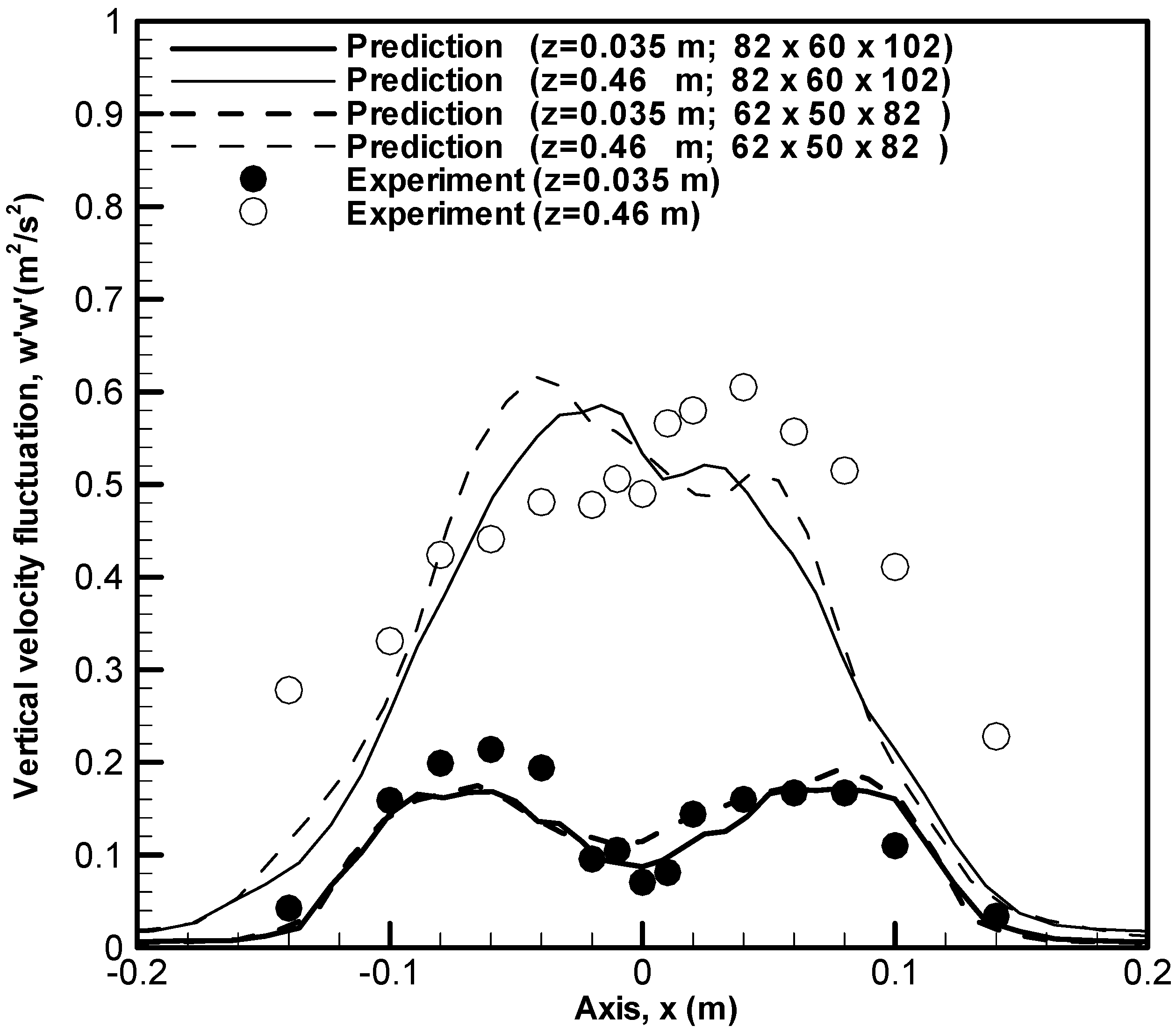
17], temperatures were obtained by means of fine wire thermocouples, and velocity and its fluctuation were determined using a two-component laser Doppler velocimetry (LDV) system. Profiles of the root-mean-square (RMS) value of the longitudinal velocity fluctuation,
w′
w′, and the transverse one,
u′
u′, obtained from the two grid systems at
z = 0.035 m and 0.46 m, are compared with the experimental data in
Figure 1 and
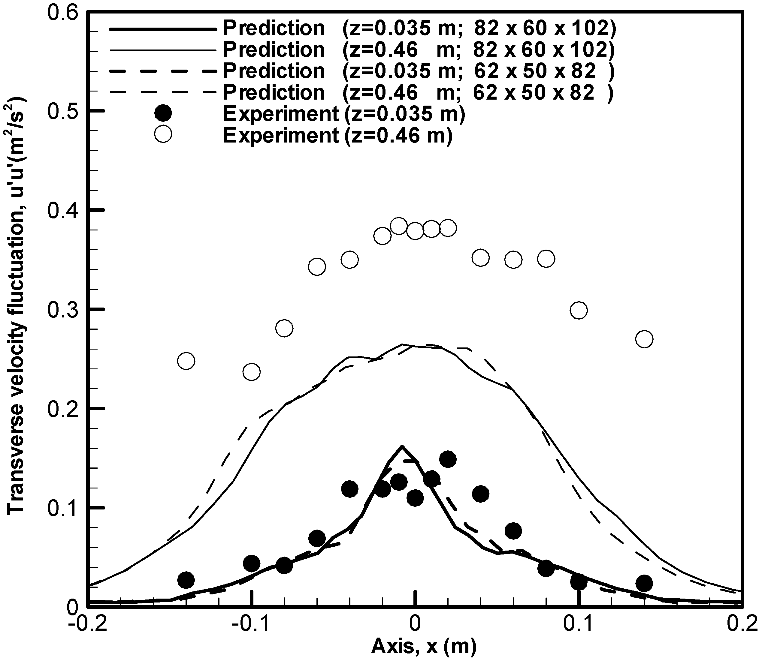
Figure 2. The calculated transverse velocity fluctuation,
u′
u′, is about 25% too low in the plume region (
z = 0.46 m). Nevertheless, both the prediction and experiment suggest that the reacting flow field is displaced in a stronger flapping manner. Globally, the numerical model is capable of reproducing the mechanism generating the buoyant instability present in the early development of the flame (
z = 0.035 m) and the transition to turbulence in the plume region (
z = 0.46 m).
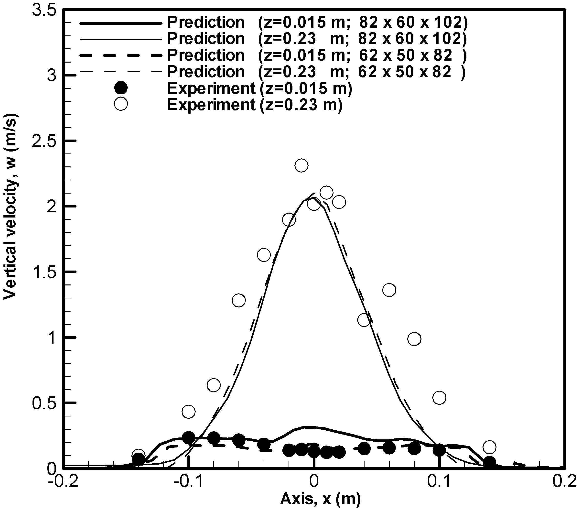
Figure 3,
Figure 4 and
Figure 5 show that the general shape of the experimentally-determined temperature and velocity profiles is correct. The computations over-predict the transverse velocity,
u, at the fire base (
z = 0.015 m) and underpredict the velocity and the temperature in the plume region (
z = 0.23 m). These LES computations are practically grid independent. It can be concluded that the grid system determined from the fire characteristic length offers the best tradeoff between accuracy and cost for the present purpose.
Figure 1.
Profiles of the measured and predicted longitudinal velocity fluctuation, w′w′, at z = 0.035 and 0.46 m.
Figure 1.
Profiles of the measured and predicted longitudinal velocity fluctuation, w′w′, at z = 0.035 and 0.46 m.
Figure 2.
Profiles of the measured and predicted transverse velocity fluctuation, u′u′, at z = 0.035 and 0.46 m
Figure 2.
Profiles of the measured and predicted transverse velocity fluctuation, u′u′, at z = 0.035 and 0.46 m
Figure 3.
Profiles of the measured and predicted temperature at z = 0.015 and 0.23 m.
Figure 3.
Profiles of the measured and predicted temperature at z = 0.015 and 0.23 m.
Figure 4.
Profiles of the measured and predicted longitudinal velocity at z = 0.015 and 0.23 m.
Figure 4.
Profiles of the measured and predicted longitudinal velocity at z = 0.015 and 0.23 m.
Figure 5.
Profiles of the measured and predicted transverse velocity at z = 0.015 and 0.23 m.
Figure 5.
Profiles of the measured and predicted transverse velocity at z = 0.015 and 0.23 m.
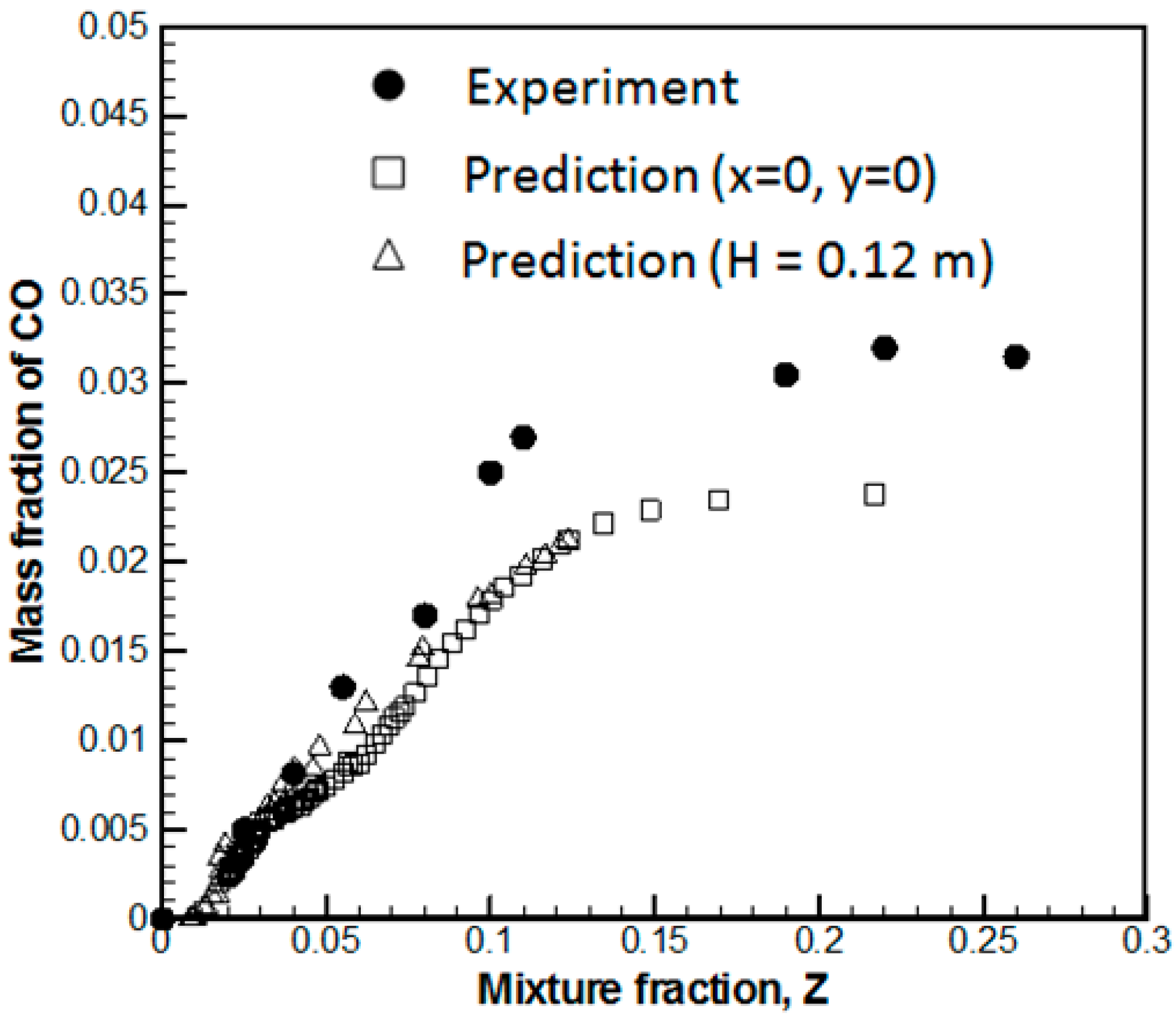
Orloff [
15] performed detailed measurement for the chemical species, such as CO and soot, from a low Froude number propane and propylene-free pool fire of 178 kW by using a porous burner of 0.75 m in diameter. Based on the fire characteristic length, a grid system containing 70(
x) × 70(
y) × 100(
z) with uniform cell sizes of 2 cm is chosen. The predicted CO molar fraction in a traverse
versus radial position at
H = 5.2 cm and along the centerline against the average mixture fraction,
Z, is plotted in
Figure 6. The magnitude of CO is well predicted, and the computed profiles exhibit the same similarity that is observed experimentally. The peak in the carbon monoxide is predicted just inside the flame, and CO declines significantly far away from the fire region. Turbulent mixing and fluctuations reduce the peak of CO concentrations as compared to that in laminar diffusion flames [
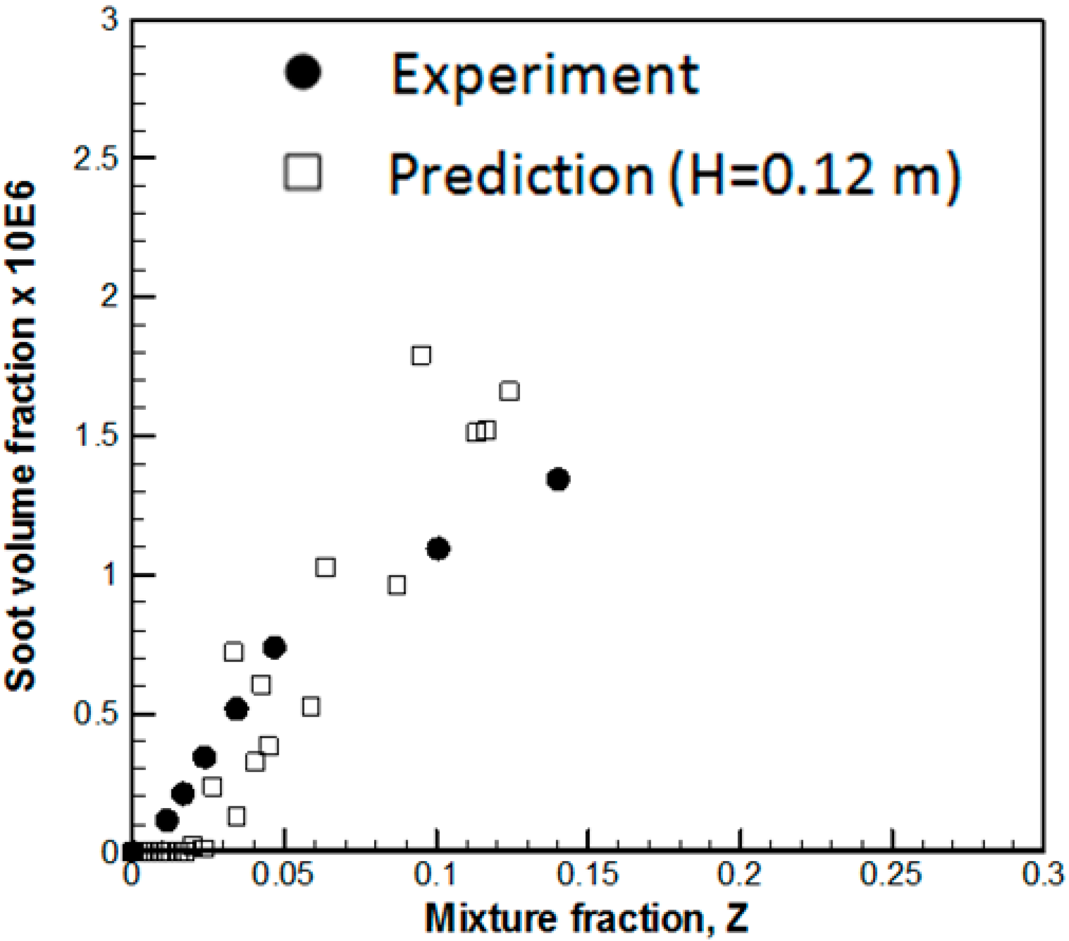
15]. Both the experiment and prediction show that the local concentration of CO in the fire is correlated solely as a function of mixture fraction because buoyant turbulent diffusion flames at the intermediate scale generally have modest stretch rates. This implies that the CO generation depends essentially on the fuel type and is relatively independent of position in the over-fire region, of pool diameter and of heat release rate. The soot volume fraction
versus radial position in a traverse position at
H = 0.12 m above the propylene pool fire is shown in
Figure 7. The predicted and measured profiles of soot show a high degree of similarity in the flame close to the fuel-rich condition (
Z > 0.1). This implies that soot formation is likely subject to precursors, consistent with the hypothesis that the smoke point is the controlling parameter for soot formation. Past the flame tip, a significant amount of soot in the experimental flame [
15] is not computed, particularly under the fuel-lean condition (
Z < 0.1). That means that the transition from soot formation to oxidation occurs more quickly in the simulation than in the experiment, indicating that the model for the spatially-varying soot oxidation process needs adjustment. Besides, past the flame tip, soot surface growth may continue after its oxidation has ceased, causing a significant amount of soot to be sustained there. The influence of turbulent fluctuations, strong temperature and fuel-dependent effects on soot surface growth cannot be captured by the smoke-point concept in its present form. This helps explain the limited success of smoke-point attempts to predict soot emissions in fuel-lean conditions. The developed framework considers only the phenomena essential for obtaining sufficiently accurate predictions of chemical species and soot production in non-premixed turbulent flames of several engineering calculations. The Smagorinsky sub-grid model is known to be too dissipative, particularly for an insufficient grid refinement. An extremely small grid size (mm) is required to fully resolve the complex flow instabilities from a turbulent buoyant flame, making practical fire simulations difficult. Such a pulsing behavior also makes accurate measurements difficult. It seems most likely that the discrepancies are due to a combination of the experimental uncertainties and the possible error in the numerical simulation.
Figure 6.
Comparison between the measured and predicted CO mass fraction as a function of the average mixture fraction
Figure 6.
Comparison between the measured and predicted CO mass fraction as a function of the average mixture fraction
Figure 7.
Comparison between the measured and predicted soot volume fraction as a function of the average mixture fraction at a height of 12 cm.
Figure 7.
Comparison between the measured and predicted soot volume fraction as a function of the average mixture fraction at a height of 12 cm.
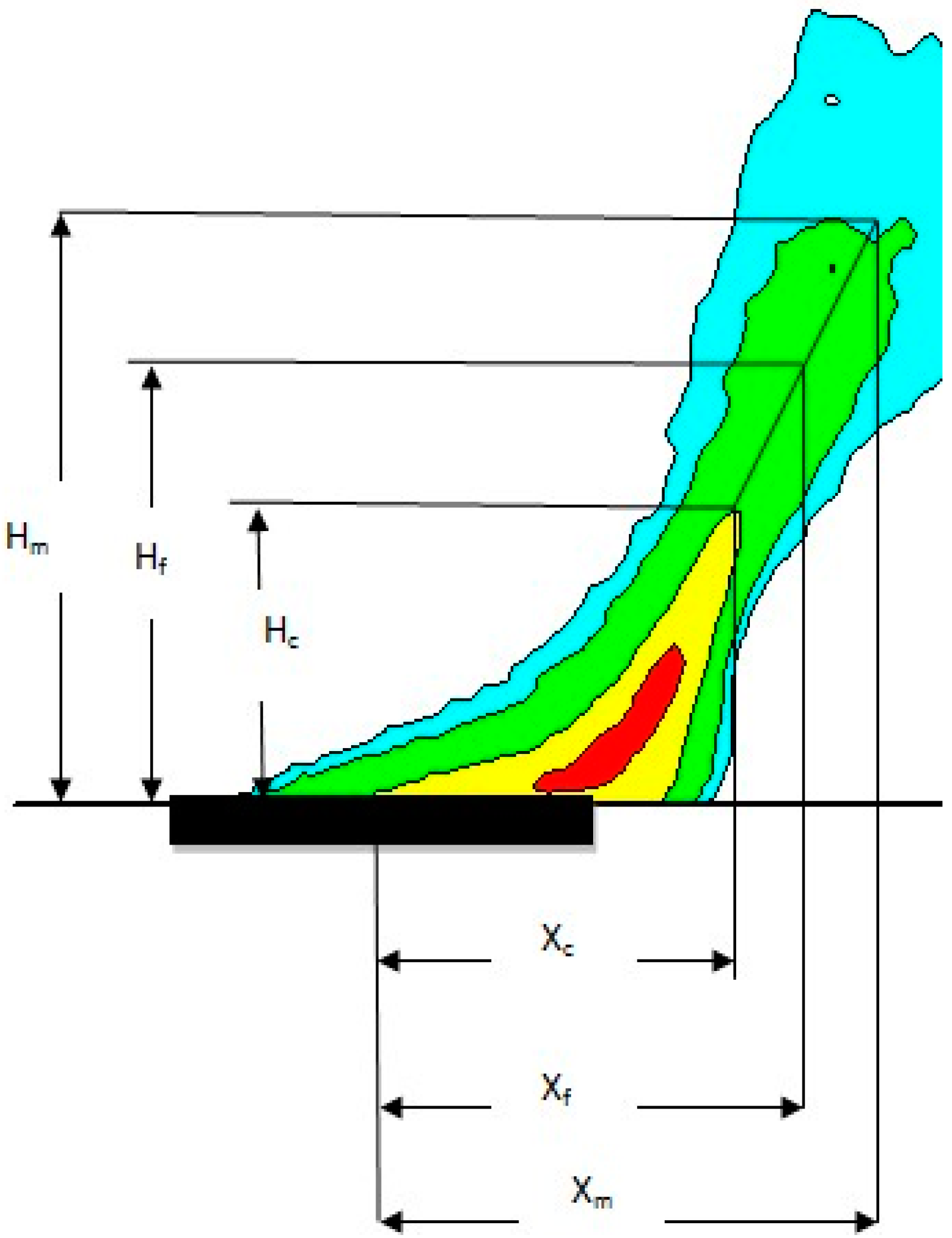
Kolb [
18] performed measurements of the flame shape and heat flux on the median plane from a pool fire in crossflow with a velocity varying from 0.7 to 2 m/s, as shown in
Figure 8. This fire with a heat release rate of 45 kW is supplied by using a propane burner with a length,
xb, of 0.25 m and a width of 0.4 m. Turbulent flames exhibit a pulsing behavior, and a mapping flame luminosity technique [
18] using a CCD camera was developed to measure the visible flame shape through image processing using a selected luminosity threshold. This technique is based on the flame presence probability, and the mean flame length/height (
Xf/
Hf) are derived from the maximum flame ones (
Xm/
Hm) corresponding to the presence probability of 0.05 and the continuous ones (
Xc/
Hc) corresponding to the presence probability of 0.95. It was checked that the so-determined persistent flame shape can be defined as
Xf = 0.5(
Xm +
Xc) and
Hf = 0.5(
Hm +
Hc), corresponding to a gas temperature of about 450–500 °C. According to the experiment, for a heavily sooting flame, the visible flame shape corresponds to the zone where the gas temperature is higher than 500 °C. Determination of the visible flame extent with such a criterion (500 °C) is of particular concern in considering the ignition of adjacent objects by radiation and, as a consequence, the flame propagation. By using this criterion for determining the flame shape, the predicted flame height (
Hf) and length from the leading edge (
Lf =
Xf + 0.5
xc) are compared with the experimentally-determined ones in
Figure 9 as a function of crossflow velocity. Both the experiment and prediction show that the extent of the visible flame, L
f, progressively increases; however, the flame height decreases with an increase of the wind velocity. As compared to the experimentally-determined flame length, an overprediction of 10% for
U0 = 0.5 m/s and an underprediction of 20% for
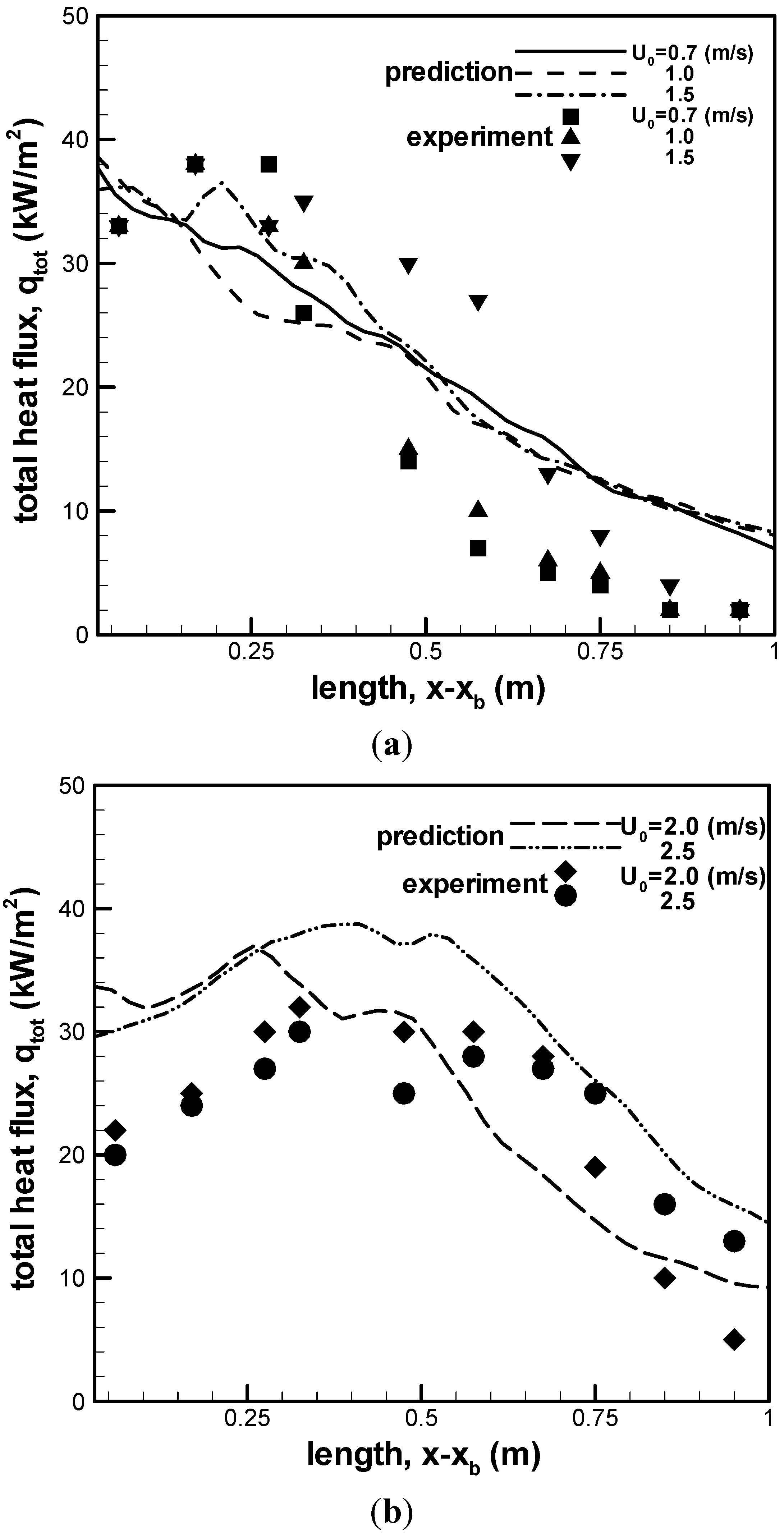
U0 = 1.5 m/s are found. The flame at low wind velocity is roughly six-times thicker than that at high wind velocity, mainly due to buoyancy and air entrainment. If the stoichiometric coefficient (continuous zone) is used for determining the predicted flame shape, a big difference between the predicted flame shape and existing experimental data will be derived due to the different criteria. During experiment, the heat feedback to the wall was measured by mounting the radiometer aperture of a 150° view angle. The predicted and measured mean flame-surface heat flux downstream behind the burner (
x −
xb > 0), along the burning wall centerline (
y = 0.2 m), is presented in
Figure 10a,b. In spite of the discrepancy, the magnitude and distribution of the heat flux closely follow the general behavior of the experimental data in a range of wind velocity from 0.7 to 2.5 m/s. Just downstream behind the burner (
x −
xb < 0.25 m), the total heat flux is found to decrease with an increase of the wind velocity due to a reduction in the flame thickness. Far away from the burner (
x −
xb > 0.5 m), the total heat flux, as a whole, is proportional to the wind velocity mainly due to an increase of the flame extent. Rigorous comparison between prediction and measurement is again difficult for the buoyantly-controlled flame, which produces oscillatory behavior in the flame structure in a cyclic fashion, yielding the measurement error with an uncertainty of 10%–15%.
Figure 8.
Pool fire in the crossflow and definition of the visible flame shape on the median plane.
Figure 8.
Pool fire in the crossflow and definition of the visible flame shape on the median plane.
Figure 9.
Comparison between the predicted and measured flame height/length as a function of the wind velocity.
Figure 9.
Comparison between the predicted and measured flame height/length as a function of the wind velocity.
Figure 10.
Comparison between predicted and measured total heat flux from the flame to the wall surface downstream behind the burner. (a) Heat flux for U0 = 0.7, 1 and 1.5 m/s; (b) heat flux for U0 = 2 and 2.5 m/s.
Figure 10.
Comparison between predicted and measured total heat flux from the flame to the wall surface downstream behind the burner. (a) Heat flux for U0 = 0.7, 1 and 1.5 m/s; (b) heat flux for U0 = 2 and 2.5 m/s.
3.2. Large-Scale Fire
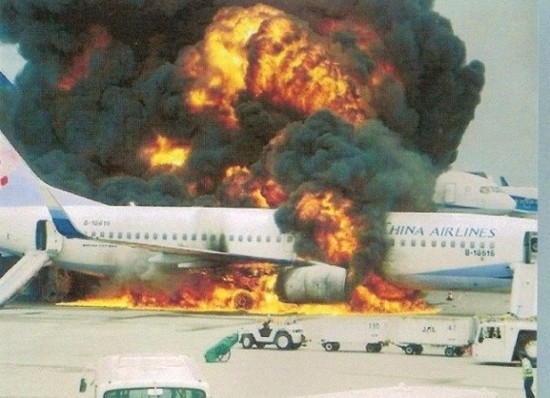
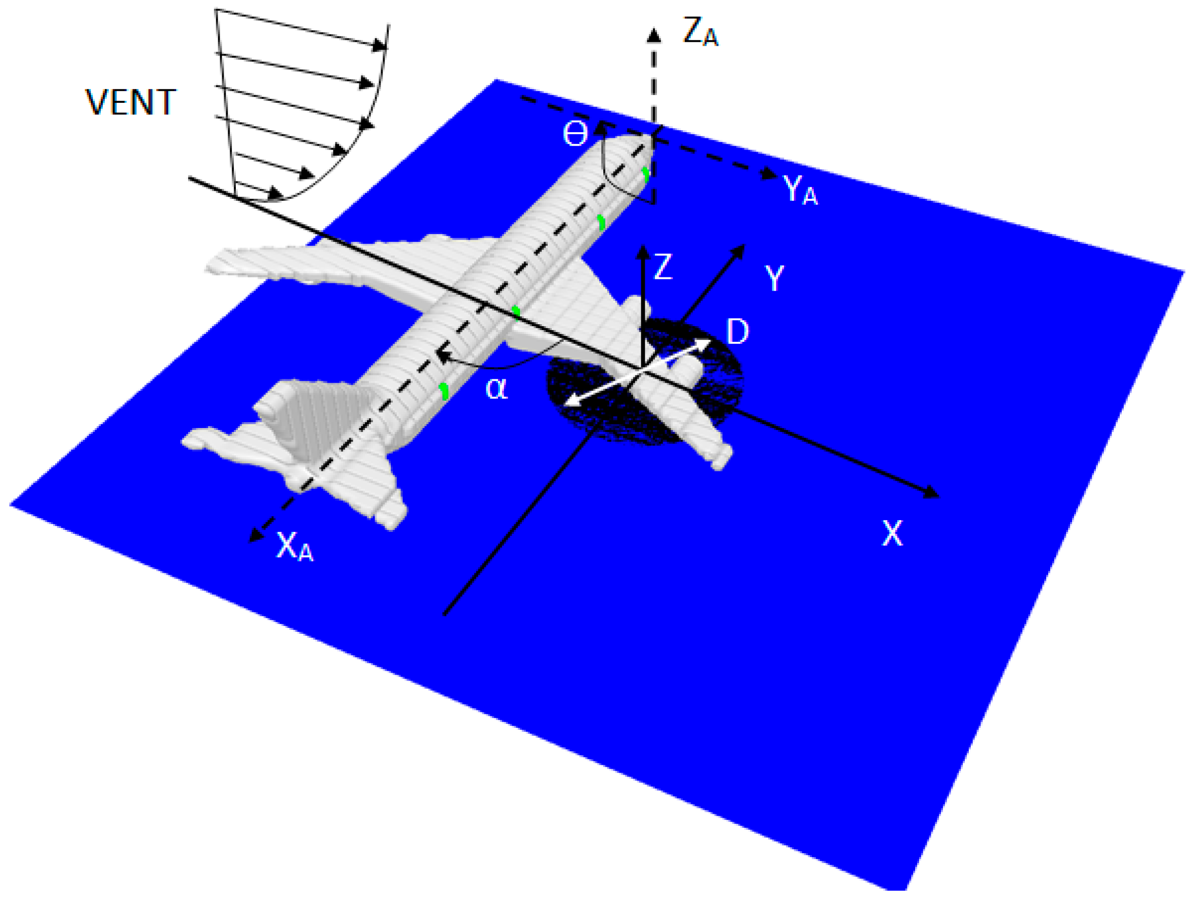
A schematic diagram of a post-crash pool fire (
D = 20 m) engulfing a composite-type aircraft (for example, A350) and the coordinate system in the numerical simulation are shown in
Figure 11. The calculations were performed using a computational mesh, which was made up of 200 × 200 × 250 cells with an overall dimension of 90 m in length (
x), 90 m in width (
y) and 100 m in height (
z). The grid is locally refined, with extra grid points being added in strong shear stress zones, such as near the pool fire surface and in the wake region around the aircraft. Along the length,
x, cell sizes start at 0.15 m around the pool fire and stretch to about 1 m at the free boundary. In the z direction, cell sizes are approximately 0.1 m in the vicinity of the burning zone and stretch to about 1.2 m near the free boundary. A uniform grid is used with a cell size of approximately 0.45 m in the transversal direction, y. In general, the fire dynamic behavior at a large scale is qualitatively correct when the aspect ratio of cells is below 5, as proposed by FDS [
16]. Upon encountering the perturbation induced by an aircraft in the crosswind, the boundary layer probably changes rapidly from transition into a fully turbulent one. The viscous sublayer is critically dependent on the near-wall model due to important viscous effects. An extremely small grid size (mm) is required to fully resolve the turbulent boundary layer and the complex flow instabilities in the wake around the aircraft for the high Reynolds number flow, making practical fire simulations difficult. In the present work, the computational nodes immediately adjacent to a wall are located in the fully turbulent region, and this simplicity allows faster computations and, by this, a higher spatial discretization and an increase of the resolved part of the fire oscillation. Besides, predictions of the most dominant radiative heat transfer are generally less sensitive to the near-wall turbulence model. It was found that the mildly-stretched grid system with a moderate computational domain offered the best tradeoff between accuracy and cost. With the use of a highly-compressed grid system, the build-up of numerical error could produce spurious results over the course of an LES calculation due to commutation of the filtering operation. Up to now, investigations of a large-scale fire are limited to computations on relatively coarse meshes everywhere [
4,
14].
Figure 11.
Schematic diagram of the occurrence of large fires engulfing an aircraft and the coordinate system in the numerical simulation.
Figure 11.
Schematic diagram of the occurrence of large fires engulfing an aircraft and the coordinate system in the numerical simulation.
The atmospheric condition, characterized by fluctuations in wind speed and direction, cannot be taken into account in the current simulation. The composite-type aircraft orientation relative to the external post-crash fire in the crosswind, the area of spill and the volume of fuel are the important parameters. Therefore, the scenarios of an aircraft post-crash fire are highly variable, because of the extremely varied nature of wind conditions. Therefore, the influence of deviation in the wind speed on the behavior of the fire is studied by taking into account a speed range of 0–10 m/s. The effects of aircraft orientation relative to the wind direction, characterized by an angle α that varies from 0° to 360° (
cf. Figure 11), on the major changes in the overall flame structure and, consequently, the heat flux on the fuselage skin, are also taken into account.
3.2.1. Instantaneous View of the Thermal Plume
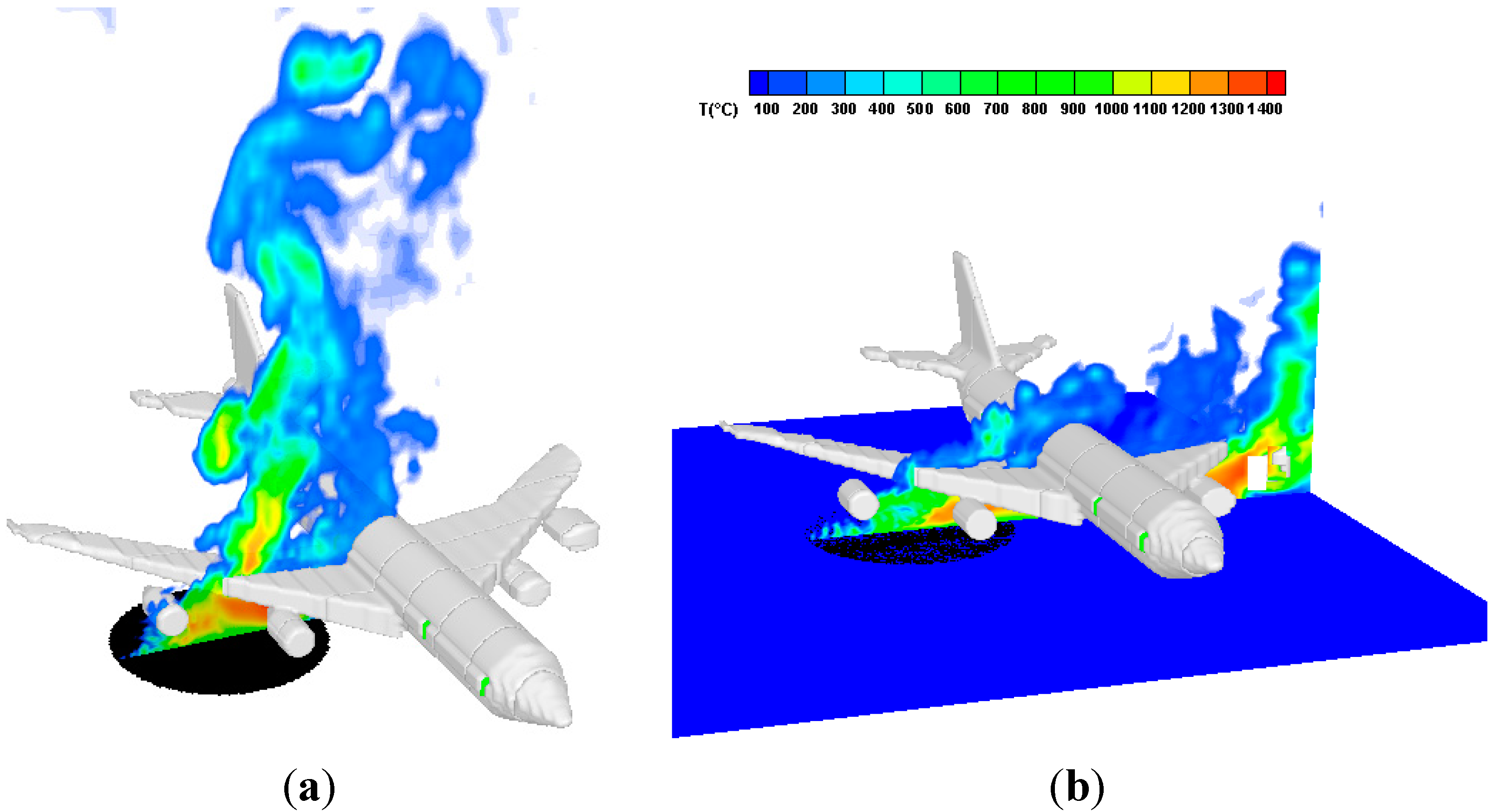
The instantaneous shape of the flame where the gas temperature is higher than 500 °C, from the liquid fuel in the plane perpendicular to the fuselage for two wind speeds (
U0 = 2 and 10 m/s), is illustrated in
Figure 12a,b. Surrounding the cone of fuel vapor is a zone of luminous persistent flame. Above this zone is a further combustion region, but here, there is intermittency and obvious turbulence in the flaming. Finally, there is the non-reacting buoyant plume, which is generally turbulent in nature and characterized by decreasing velocity and temperature with height. Wake regions are formed around aircraft, and at times, spiraling vortex flows are seen in the plume. For a low Froude (ratio between buoyant and inertia forces) number flame (
U0 = 2 m/s,
Figure 12a), shear-stresses between hot combustion products and fresh air make the flow unstable and amplify oscillations near the fire base due to air entrainment variation and flame flicker, inducing large eddy structures corresponding to hot gas puff burning. Fresh air entrained by these vortexes feeds the flame with oxygen and cools the smoke, influencing natural convection and then air entrainment. In the natural convection limit, as the Froude number increases (
U0 = 10 m/s,
Figure 12b), coherent structures appear also surrounding the cone of fuel vapor, the flame presenting a pronounced instability due to crossflow. The wind effect is the tilting of the plume, such that there are times when the aircraft is not fully engulfed by the flame. There are other complications deriving from the intermittency of the behaviors, with luminous regions of efficient combustion appearing randomly on the outer surface of the fire according to the turbulent fluctuations in the fire plume.
Figure 12.
Instantaneous view of the predicted thermal plume. (a) Low wind speed of 2 m/s; (b) high wind speed of 10 m/s.
Figure 12.
Instantaneous view of the predicted thermal plume. (a) Low wind speed of 2 m/s; (b) high wind speed of 10 m/s.
3.2.2. Time Averaged Thermal Plume
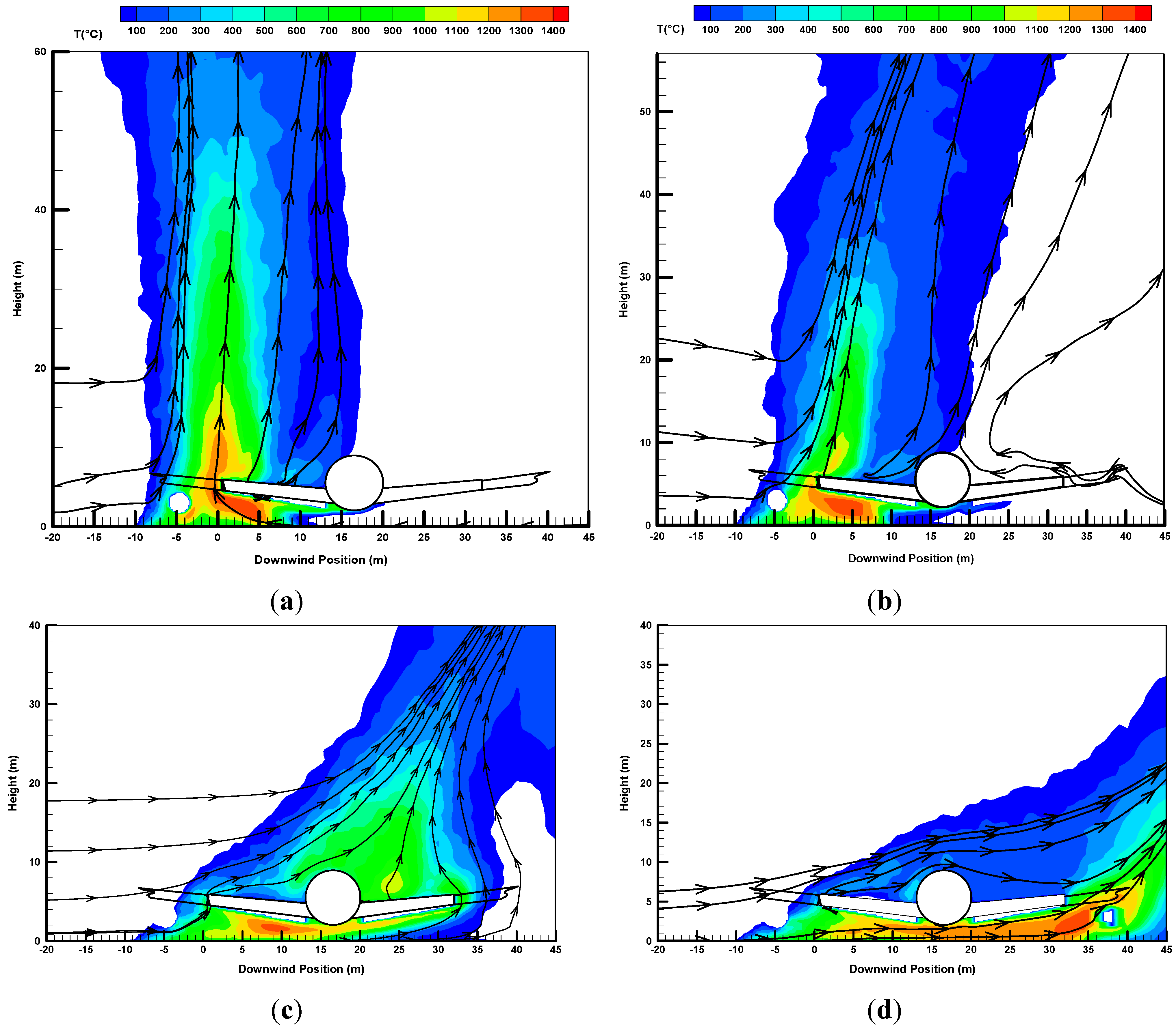
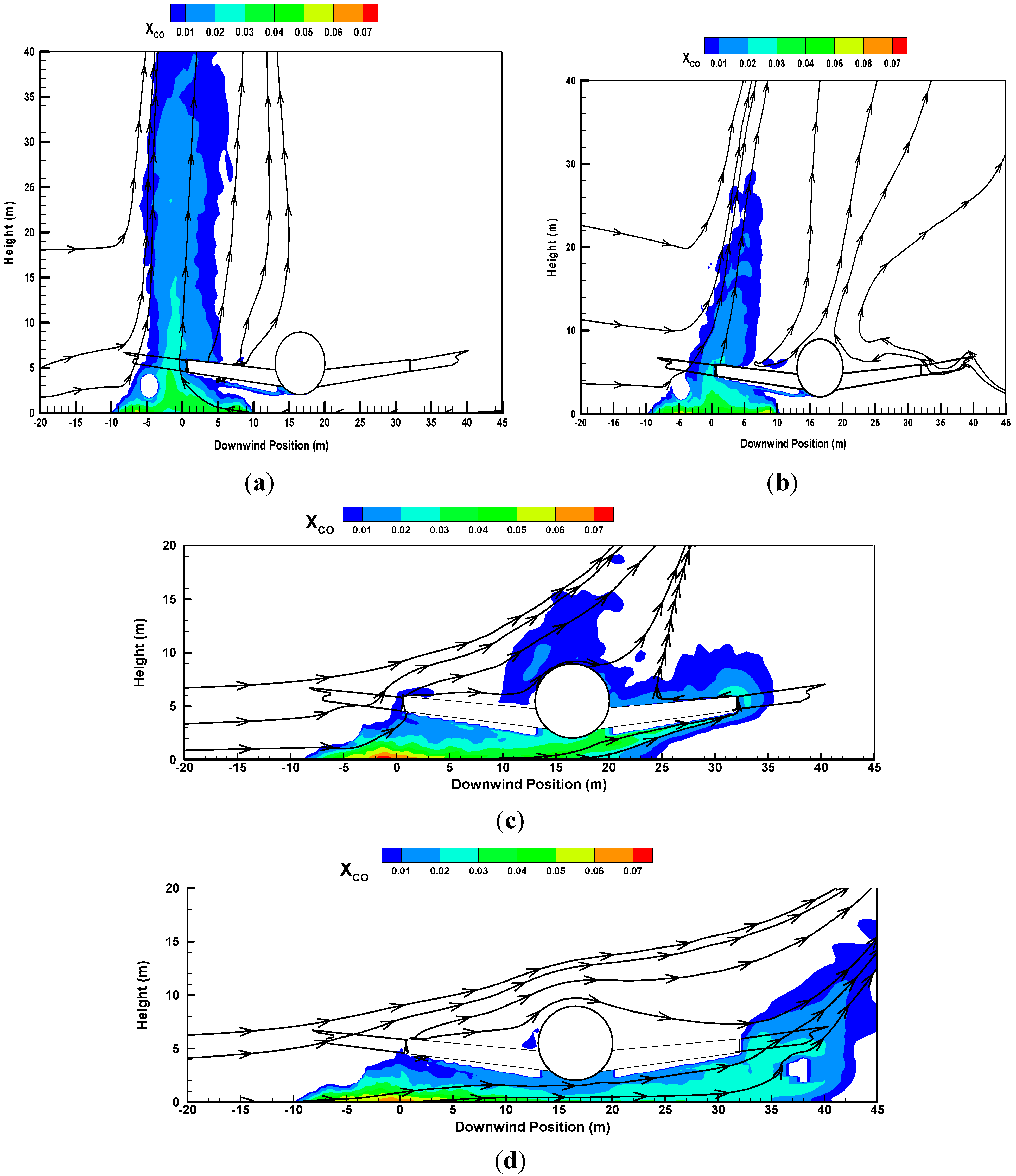
The time-averaged temperature, CO molar fraction and soot mass fraction on a wind-assisted liquid fire engulfing an aircraft are presented in
Figure 13,
Figure 14 and
Figure 15. The time period over which the computation outputs were averaged from the last 60 s is considered as a quasi-steady period. It should be noted that for such a large-scale kerosene pool fire in crossflow, there is no link between the carbon monoxide concentration and the mixture fraction. The prediction suggests three main behaviors under a variety of wind conditions.
- 1)
Under a quiescent condition, the main part of the flame,
i.e., the primary flame zone, is essentially vertical, as shown in
Figure 13a. The quiescent fire consists of a buoyancy-dominated flame zone with a peak temperature of 1400 °C. The pool fire is located near the fuel source and far away from the aircraft. There is an excess of fuel due to the degradation of the composite material over the wing skin. This situation induces an increase in the thermal plume volume with time during the fire growth stage, containing large CO (
cf. Figure 14a) and soot (
cf. Figure 15a) with a peak value of 10% in the mass fraction.
- 2)
With the presence of a low wind speed (
cf. Figure 13b,
Figure 14b and
Figure 15b at
U0 = 2 m/s), the crossflow is significantly deflected near the fire source as a result of an enhanced thermal blockage by the buoyancy forces. Air entrainment and wind velocities can be of the same order of magnitude. The wind restricts the flow of entrained air and produces highly-mixed and, therefore, highly-combusting regions below the wing adjacent to the pool of the liquid fuel. However, the magnitude of the wind speed is insufficient to direct the flame towards the fuselage, and to reduce the CO and soot levels in the plume region.
- 3)
For the medium wind speed (
cf. Figure 13c,
Figure 14c and
Figure 15c at
U0 = 5 m/s), the flame is elongated in the downstream direction, and the region directly surrounding just in front of the aircraft is immersed in the highly-combusting zone with a peak temperature of 1300 °C due to complex wind/vorticity interactions. Flow is moving over the top of the aircraft, creating streamwise vortices, while fuel-rich air is forced below the fuselage. This situation induces an increase of the flame cover with a temperature level of about 700 °C, accompanied by the presence of CO and soot on the upper leeward side of the aircraft. It is found that the presence of a composite-type aircraft instead of an aluminum type one results in a significant increase of approximately one time in the temperature level over the top of the aircraft. Besides, on the leeward side of the aircraft, the enhanced convective transport, as a whole, leads to a significant amplitude of temperature (1300 °C), of the CO molar fraction (5%) and of soot mass fraction (7%).
- 4)
The high wind speed (
U0 = 10.2 m/s) enhances the interaction between the crossflow and aircraft and, consequently, facilitates the global flame shape alterations (
cf. Figure 13d), which are combined with global enhancements in turbulent mixing. The windward flow is strongly accelerated over the top of the aircraft, allowing the suppression of the flame cover (
T < 300 °C), CO and soot due to increased convective transport. Besides, the fuel-rich flow is ejected from underneath the aircraft, and this creates a second high temperature zone (1400 °C) accompanied by large CO (
cf. Figure 14d) and soot (
cf. Figure 15d) productions (10% in mass fraction) on the leeward side of the aircraft due to enhanced mixing by the presence of the vortices in the wake behind the aircraft. The magnitude of the wind speed is sufficient to direct the flame to the bottom surface of the fuselage, causing an excess of the fuel gas due to the pyrolysis of the composite material over the fuselage skin. The oxygen within the gap is insufficient to consume the fuel accumulated inside the gap, and the combustion within a vitiated gap is probably close to the rich limit of flammability with a flame temperature of about 1200 °C.
Overall, the predicted trend is consistent with the experimental findings of Suo–Anttila [
5,
6] from a large fire engulfing a cylindrical objet in the crosswind. The length of flame base drag (
T > 1200 °C) is approximately one-time the pool size for the medium wind speed (
U0 = 5 m/s) and up to 1.5-times the pool size for the highly ventilated (
U0 = 10 m/s) fire. In a given deployed position of aircraft related to the direction of incident wind, the most straightforward changes in the flame geometry as a function of the magnitude of the wind speed are numerically reproduced.
Figure 13.
Contours of the time-averaged temperature for fires containing an aircraft of the composite type. (a) Quiescent condition; (b) low wind speed of 2 m/s; (c) medium wind speed of 5 m/s; (d) high wind speed of 10 m/s.
Figure 13.
Contours of the time-averaged temperature for fires containing an aircraft of the composite type. (a) Quiescent condition; (b) low wind speed of 2 m/s; (c) medium wind speed of 5 m/s; (d) high wind speed of 10 m/s.
Figure 14.
Contours of the time-averaged CO molar fraction for fires containing an aircraft of the composite type. (a) Quiescent condition; (b) low wind speed of 2 m/s; (c) medium wind speed of 5 m/s; (d) high wind speed of 10 m/s.
Figure 14.
Contours of the time-averaged CO molar fraction for fires containing an aircraft of the composite type. (a) Quiescent condition; (b) low wind speed of 2 m/s; (c) medium wind speed of 5 m/s; (d) high wind speed of 10 m/s.
Figure 15.
Contours of the time-averaged soot mass fraction for fires containing an aircraft of the composite type. (a) Quiescent condition; (b) low wind speed of 2 m/s; (c) medium wind speed of 5 m/s; (d) high wind speed of 10 m/s.
Figure 15.
Contours of the time-averaged soot mass fraction for fires containing an aircraft of the composite type. (a) Quiescent condition; (b) low wind speed of 2 m/s; (c) medium wind speed of 5 m/s; (d) high wind speed of 10 m/s.
3.2.3. Heat Flux Distribution on the Fuselage Skin
For a large-scale fire, radiation flux seems the central and dominant mode of heat transfer, convection flux playing a secondary role [
24]. The wind direction directly affects the view factor from the flame to the fuselage skin and, consequently, the maximum heat flux. The peak in heat flux is the highest when the aircraft moving direction is perpendicular to the crosswind (α = 270°). The radiation heat flux to the surrounding fuselage skin depends mainly on three factors: (1) the flame volume and its temperature level; (2) the concentrations of gaseous and particulate soot emitting species; (3) the view factor from flame to the exposed fuselage skin.
Turbulent flames exhibit a pulsing behavior, and the oscillatory nature of the incident heat flux on the surface of the fuselage within the flame volume is always visibly apparent. The fluctuations demonstrate the effects of the characteristic large-scale turbulence of a free pool fire and wind. The fluctuations in heat flux for the medium wind speed are generally smaller than those for the low one. This phenomenon is believed to be due to the fact that the medium wind damps out the buoyancy forces in the flame. The time-averaged heat flux distribution over the fuselage skin in a quasi-steady period is the main parameters of interest, as illustrated in
Figure 16a,b for medium (5 m/s) and high speeds (10 m/s). The heat flux on the fuselage skin is an increasing function of the intensification of the turbulent flame on the fuel-rich region. The heat flux on the fuselage skin is below 50 kW/m
2 for a wind speed below 2 m/s. This is due to the fact that the weak crossflow is deflected by the pool fire due to the buoyancy-induced air entrainment, and this prevents the flame from reaching the fuselage. In all of the cases, the flame height and its volume increase with the theoretical heat release rate, and the peak in heat flux on the fuselage skin becomes significant when the pool size exceeds 20 m.
For medium wind (
cf. Figure 16a), the mean heat flux is considerably higher with a magnitude of 200 kW/m
2 on the windward side of the fuselage due to an impingement of the buoyant plume on the fuselage surface. The peak in heat flux is a factor of four increase relative to quiescent fires, and this trend is in agreement with the measured one for large fire [
5,
6,
33]. The substantial thermal radiation develops also on the leeward side of the fuselage when it is immersed in a fire, resulting in a circumferential variation in the heat flux distribution. The heat flux increases to a maximum along the periphery to the underside of the fuselage. A dramatic horizontal variation in heat flux to the fuselage skin can be induced due to asymmetries in wind conditions, which cause the redirection of the flame zone by the wind component parallel to the axis of the fuselage.
The high wind speed of 10 m/s leads to a shallower smoke plume, and a region of increased heat flux to 200 kW/m
2 occurs only underneath the mock fuselage (
cf. Figure 16b). A dramatic reduction in heat flux is brought about beyond that region due to the absence of the flame. The increase of the wind speed results in only an alteration of the distribution of the incident heat fluxes to the fuselage skin. It is found that the peaks in heat flux for the medium and high wind speeds are almost equal in magnitude. There are trends for the angular variation in heat fluxes: the bottom of the fuselage demonstrates the highest heat fluxes; the windward and leeward sides follow closely; and the upper part demonstrates the lowest heat fluxes. The minimum heat flux exists on the top of the fuselage, consistent with the thin flame cover there (
cf. Figure 13d). As an illustration, the mean heat flux distribution over the wing skin is shown in
Figure 17. The extent of the higher heat flux to the wing skin rises with an increase of the wind speed as a result of acceleration of the flow underneath the mock fuselage, creating a well-mixed region, which can significantly strengthen the burning rate of the composite material. The fact that the heat flux values on the wing skin are higher indicates that an actively burning region over the wing surface is present. The magnitudes of the heat fluxes in excess of 240 kW/m
2 exist over the two wings’ skin due to a large flame base drag (
cf. Figure 6).
Figure 16.
Iso-contour of the incident heat flux on the fuselage skin. (a) Wind speed of 5 m/s; (b) wind speed of 10 m/s.
Figure 16.
Iso-contour of the incident heat flux on the fuselage skin. (a) Wind speed of 5 m/s; (b) wind speed of 10 m/s.
Figure 17.
Iso-contour of the incident heat flux on the wings’ skin.
Figure 17.
Iso-contour of the incident heat flux on the wings’ skin.
3.2.4. Burning Rate over the Composite-Type Fuselage Skin
Changes in the maximum burning rate over the fuselage skin depend on the orientation of aircraft relative to the wind direction due to global flame zone redirection. The peak in the burning rate is the highest when the aircraft moving direction is perpendicular to the crosswind (α = 270°). Iso-contours of the predicted burning rate on the fuselage skin in such a situation are illustrated in
Figure 18a–d at various wind velocities. Over each side, the surface burning corresponds to a signal representing the presence of flames above the region. The circumferential variations in the surface burning are the result of fluctuating, not uniform temperature fields due to interaction between the buoyancy and inertia forces. A critical heat flux of 30 kW/m
2 is predicted, below which the pyrolysis enters the decay phase rapidly.
- 1)
For the low wind speed (
U0 < 2 m/s,
cf. Figure 18a,b), a burning rate higher than 15 g/m
2·s occurs only on the windward side as a result of the attachment of the actively-combusting region to the fuselage skin adjacent to the pool fire.
- 2)
The resulting burning rate becomes tightly coupled to fire environment with the medium wind speed (
U0 = 5 m/s,
cf. Figure 18c). The plume is displaced, which brings about a significant change to the radiation distribution and, hence, the vaporization rate of the composite material. This supports the postulation of an interaction between the aircraft and the fire that surrounds it. The burning rate with a magnitude of 12 g/m
2·s occurs on the windward side of the fuselage due to the impingement of the buoyant plume on the fuselage skin. The burning rate is the highest at the leeward side with a value of 16 g/m
2·s and decreases appreciably at the other sides. A substantial thermal radiation takes place on the leeward side of the fuselage when it is immersed in a fire, resulting in a moderate circumferential variation in the burning rate.
- 3)
For the high wind speed (
cf. Figure 18d), a magnitude of the burning rate in excess of 20 g/m
2·s exists on the leeward side of the fuselage due to a large flame base drag (
cf. Figure 13d). The predicted fuel recession rate of composite material follows closely the one measured during the course of the experiment in a cone calorimeter. The minimum burning rate exists on the top of the fuselage, consistent with the thin flame cover there. The mass loss rate over the top surface of the fuselage suggests an inverse dependence with the wind velocity beyond 5 m/s.
The history of the global mass loss rate of the composite material averaged over the total pyrolysis surface is presented in
Figure 19 at various wind speeds. It is seen that during the flame spread period, the mass loss rate increases quickly when an actively-burning region over the composite surface is present and is generally higher at strong wind velocity. For a wind speed below 2 m/s, the flame stands up into a plume in front of the aircraft under a buoyancy-controlled condition, and hence, about 80 s are required to start the degradation of such a composite material. The increase of the wind speed strengthens the degradation of the composite-type fuselage significantly due to the enhanced impact of the flame on the fuselage skin. When the ratio (Froude number) of the inertia force to the buoyancy one is great for a wind velocity beyond 5 m/s, only 10 s is sufficient for starting the degradation of the composite material. When the flame propagation is fully developed, the heat release rate reaches its maximum value. During the steady-state period, the burning rate per unit area of composite material increases with wind speed up to 2 m/s, beyond which limit it becomes largely independent of wind. This dependence is related to the burning regime, which becomes increasingly dominated by radiation as soot levels rise up to a value where the fire is effectively optically thick and saturated.
Figure 18.
Iso-contours of the mass loss rate over the skin of the composite-type fuselage with a wind direction of 270°. (a) Quiescent fire condition; (b) low wind speed of 2 m/s; (c) Medium wind speed of 5 m/s; (d) high wind speed of 10 m/s.
Figure 18.
Iso-contours of the mass loss rate over the skin of the composite-type fuselage with a wind direction of 270°. (a) Quiescent fire condition; (b) low wind speed of 2 m/s; (c) Medium wind speed of 5 m/s; (d) high wind speed of 10 m/s.
Figure 19.
History of the mass loss rate of the composite material for the different wind speeds.
Figure 19.
History of the mass loss rate of the composite material for the different wind speeds.
3.2.5. Burning Rate of the Liquid Fuel
These analyses consider a liquid pool fire burning at steady state after the initial stages of a fire. The heat feedback from the flame to the liquid pool surface directly affects the liquid heating rate to its boiling point of about 220 °C and, consequently, its vaporization rate. The history of the mass loss rate of liquid fuel for the different wind intensities is presented in
Figure 20. The global regression rate is found to increase from 60 g/m
2·s to a value of approximately 70 g/ m
2·s with a rise of the wind velocity to 2 m/s. A further increase of the wind speed to 5 m/s strengths the mixing of the reactants and induces the most rapid regression of the liquid fuel as a result of the enhanced heat flux. Several studies show significant increases in the burning rates of large open-air liquid pools with increased wind [
34]. The high wind speed of 10 m/s greatly attenuates radiative feedback to the liquid fuel surface due to reduction in the flame cover, thereby depressing the mass burning rate. Besides, the oxygen below the fuselage is particularly low due to the accumulated fuel inside the gap, resulting in a decrease of the mass transfer number B and, consequently, of the regression rate (
cf. Equation (23)). The mass loss rate of the liquid fuel is about 90 g/m
2·s for the wind speed of 5 m/s, which represents an increase of about 30% compared to that for a high speed of 10 m/s. The average fuel recession rate is about 6–7 mm/min as a function of the wind speed, which follows closely the fuel recession rate of 6.3 mm/min measured during the course of the experiment in a 9.1 m by 18.3 m pool [
9].
Figure 20.
History of the mass loss rate of the liquid fuel during the fire propagation over the composite-type aircraft for the different wind speeds.
Figure 20.
History of the mass loss rate of the liquid fuel during the fire propagation over the composite-type aircraft for the different wind speeds.
3.2.6. Heat Release Rate
The heat release rate for composite-type aircraft is the most intensive when the wind direction is perpendicular to the fuselage. The pyrolysis area of the composite-type aircraft increases with the wind speed during fire propagation. The ratio between the pyrolyzed area and the fuselage surface one is about 5% for the low wind speed (
U0 < 2 m/s) and reaches an asymptotic value of 30% for a wind velocity beyond 5 m/s. The turbulent nature of the flow brings fuel to the outside, where it can be combusted more efficiently, to release pluses of much more powerful energy from the flames. The history of the heat release rate (HRR) generated from the pool fire for different wind speeds is shown in
Figure 21. Globally, the total supply of energy is elevated or depressed depending on the local air-to-fuel ratios and the efficiency of mixing, affected by the wind condition. For the wind speed below 5 m/s, the heat release rate is closely correlated to the trend of the regression rate of liquid fuel. For the quiescent pool fire, the buoyancy-induced air entrainment provides a mixing of fuel to air, and the contribution of the pyrolysis of the composite material to the total heat generation is practically negligible as compared to the liquid fuel, exhibiting the lowest HRR of about 1000 MW. The high wind can alter the flame shape, as well as pyrolysis zone over the fuselage and wing skins and the entrainment phenomena. The high wind-assisted fire exhibits the highest HRR of about 1500 MW due to the large contribution of the pyrolysis of the composite material over the wing skin (
cf. Figure 17).
Figure 21.
History of the heat release rate during the fire propagation over the composite-type aircraft for the different wind speeds.
Figure 21.
History of the heat release rate during the fire propagation over the composite-type aircraft for the different wind speeds.
3.2.7. Flame Spread Rate over the Fuselage Skin
During a fire, a thermal layer containing the hot gases and soot is transported by natural or forced convection. The composite-type fuselage is gradually heated up to its ignition temperature of 390 °C by applying a heat flux up to 240 kW/m
2 from the pool kerosene fire. The gaseous products from pyrolysis of the composite materials in contact with air ignite in the flammability limits. The flame spread occurs as a result of heating of the unignited part of the fuel surface to an ignition temperature at which the pyrolysis flux exceeds a certain threshold level, essentially dependent on air crossflow. An expression for the flame spread velocity, defined as the pyrolysis front advancement rate, is derived from the following expression,
Vf = d
xp/d
t. The time for the temperature at a given position over the composite material surface to reach the ignition temperature is selected for the pyrolysis front arrival time, d
t, for calculating the pyrolysis spread rate. Temporal data, as plotted in
Figure 22 for the different wind velocities, are important in the presentation of the flame spread information, because changes in the flame propagation can be correlated with events in the fire affected by the wind condition. The high wind speed brings about important mixing and more efficient combustion, which tends to increase the flame spread rate. The numerical results suggest that the flame propagation over the composite material surface occurs in two successive modes. In the first mode corresponding to the preheating processes of the composite material, the flame spreads slowly over the fuselage skin with a mean value of 8 cm/s. The second mode is evident from a sharp rise of the flame spread rate up to 0.6 m/s in the slope of the curves due to the thermal exposure of the fuselage skin immersed in the fire environment and seen to occur at
t = 15 s. Later, the flame spread rate
Vf is essentially constant with a value of 5 cm/s when the fire propagation over the fuselage skin reaches a steady state.
Figure 22.
History of the flame spread rate over the skin of the composite-type fuselage for the different wind speeds.
Figure 22.
History of the flame spread rate over the skin of the composite-type fuselage for the different wind speeds.


