Article

Sense and Avoid Airborne Radar Implementations on a Low-Cost Weather Radar Platform

1
Intelligent Aerospace Radar Team (IART), School of Electrical and Computer Engineering, Advanced Radar Research Center (ARRC), University of Oklahoma, Norman, OK 73019-0390, USA
2
Garmin Aviation Weather Radar, Garmin International Inc., Olathe, KS 66062-3426, USA
*
Author to whom correspondence should be addressed.
Aerospace 2017, 4(1), 11; https://doi.org/10.3390/aerospace4010011
Submission received: 12 January 2017 / Accepted: 21 February 2017 / Published: 1 March 2017
(This article belongs to the Special Issue Radar and Aerospace)

Abstract

:
Traditionally, multi-mission applications in airborne radar are implemented through very expensive phased array architectures. The emerging applications from civilian surveillance, on the other hand, prefer low-cost and low-SWaP (space, weight and power) systems. This study introduces a software-based solution that intends to use low-cost hardware and advanced algorithms/processing backend to meet the remote sensing goals for multi-mission applications. The low-cost airborne radar platform from Garmin International is used as a representative example of the system platform. The focus of this study is the optimal operating mode, data quality and algorithm development in cases of all-weather sense and avoid (SAA) applications. The main challenges for the solution are the resolution limitation due to the small aperture size, limitations from the field-of-view (FOV) and the scan speed from mechanical scanning. We show that the basic operational needs can be satisfied with software processing through various algorithms. The concept and progress of polarimetric airborne radar for dual-function operations at X-band Generation 1 (PARADOX1) based on the platform are also discussed.

1. Introduction

Achieving multi-function capabilities on a low-cost airborne radar system platform has been difficult, since a low-cost radar usually does not have the quality of electronics, antenna and computing power to support advanced capabilities. However, the need for low-cost radar sensors is imperative in many areas. For example, the airborne radar on unmanned aerial vehicles (UAVs) needs to address extreme constrains on cost, space, weight and power (C-SWaP). On the other hand, unmanned aircraft still need similar (maybe more autonomous) capabilities for situation awareness compared to their manned counterparts [1]. With these challenges, there are two possible paths for the solution. One is developing higher frequency, lower cost and agile hardware, such as a metamaterial scanner [2], similar to the hardware in automobile radars [3], etc. The drawback of implementing these new hardware changes is the requirement of aircraft recertification in addition to complications that arise during the radar configuration modifications. The other path is using existing certified hardware, such as low-cost weather radars, while trying to enhance the functionalities by mainly using advanced signal processing. Because the enhancements are done in software, there is little or no need to modify existing hardware, thereby reducing the development costs and certification risks. This specific study focuses on the second path of the solution where the signal processing algorithms are developed and applied. The biggest challenge of this path is the constraint of the aperture size and scanning speed of existing low C-SWaP radars. In this study, the specific commercial weather radar platform used is the GWX™/GSX™ [4,5] airborne radars from Garmin International, Olathe, KS, USA. Table 1 lists the key system parameters of this platform. We would like to verify if the signal processing algorithms can enhance the performance of this kind of system to meet the detection and avoid (DAA) radar sensing requirements [6] or at least support the basic functionality of DAA operations as part of multi-mission operations. Also note that, although there have been FAA, RTCA (Federal Aviation Administration, Radio Technical Commission for Aeronautics) working groups actively investigating the DAA/sense and avoid (SAA) radar sensing requirements [7], the final performance requirements have not yet been finalized and released. This work has been focused on adding a basic DAA function to existing weather radar functions, rather than proposing a completely new dedicated DAA radar system.
Currently, SAA/DAA radars are under development from multiple industry entities, such as the due regard radar from General Atomics [8], Northrop Grumman’s SAA radar and initial flight tests [9]. As far as we are aware of, these on-going works have not addressed the multi-functional application for low-cost X-band radar operations, as well as the scenario of close-by multi-target tracking with angular resolution constraints. The innovative aspect of this work is the first time integration and application of some advanced algorithms for DAA/SAA functions on a low-cost airborne weather radar platform. The overall system configuration is called polarimetric airborne radar operating at X-band—Generation 1 (PARADOX1). PARADOX1 uses a single vertically-polarized antenna in current configurations, while in the future, it will have simultaneous dual-polarization capability. 
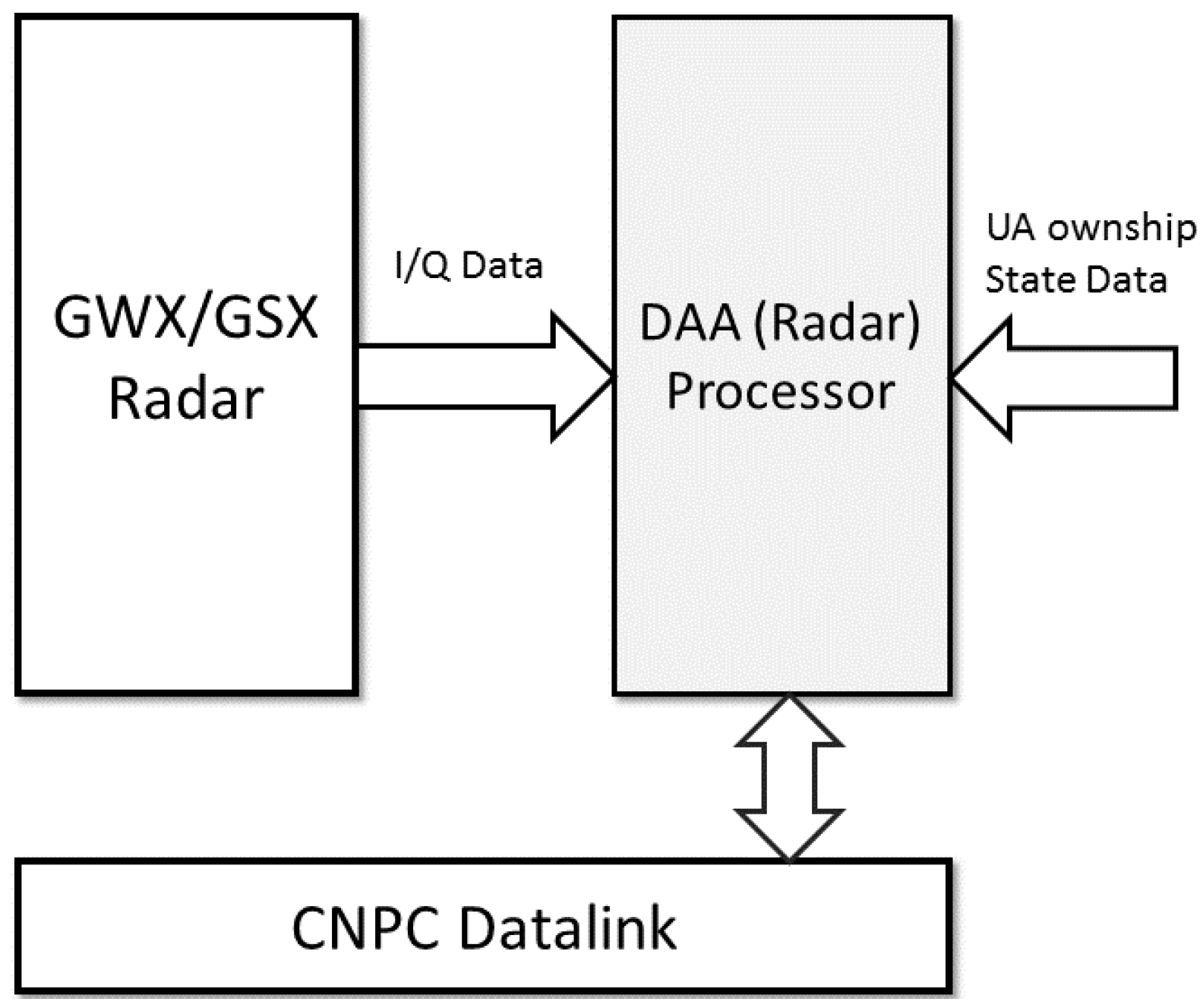
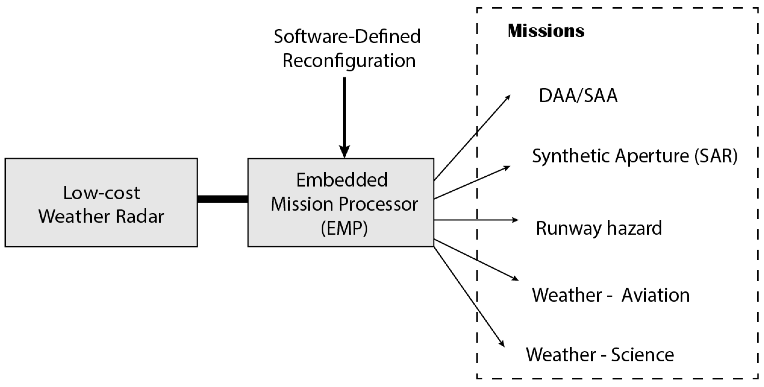
Figure 1 depicts the multi-mission concept of PARADOX1. The embedded mission processor can be configured to simultaneously execute various missions. The DAA tracking part, naturally, needs to be in track while scan (TWS) mode. Signal processing modules can be attached to the data output of PARADOX1 to achieve improvements, such as super-resolution (SR), range/azimuth/Doppler enhancement, sidelobe reduction, etc. The first significant processing module is the range-Doppler-azimuth super-resolution, which is an important step required to meet the functionality performance goals. Currently, the reiterated minimum mean square error (RMMSE)-based [10] deconvolution algorithm is applied for the azimuthal SR, and the matched filter-based iterative adaptive approach (MF-IAA) algorithm is developed for range-Doppler SR. To support real-time performance, all of the SR processing is performed after pulse compression. The target detection is based on a simple “pixel centroid” extraction from enhanced pulse compression outputs, and tracking of multiple collision hazards is implemented through the Kalman filter and joint probabilistic data association (JPDA). The end-to-end processing chain is validated through both simulations and measurements. Another novel aspect is demonstrating the simultaneous monitoring of weather and air-traffic targets through the same aperture and the same signal processing chain, which is also tested through measurements.
This paper is organized as follows: Section 2 provides more details of the DAA mission processor and the design of the complete processing flow. Section 3 focuses on real-aperture imaging processing and the super-resolution (SR) algorithm in the range-azimuth direction. Section 4 discusses the importance of the range and Doppler SR and the specific algorithms to achieve them. Section 5 provides details in the DAA tracking processing. Test results and field experiment results are introduced in Section 6. The summary and expectations for future development are provided in Section 7.

2. Detection and Avoid (DAA) Processor and Algorithms

Figure 2 shows a simplified block diagram of the current system configuration. The I/Q (In-phase/Quadrature-phase) data stream of the airborne radar is sent out through Gigabit Ethernet interface, which is then processed in real time at the external processor. There are three major steps in the processing flow: data pre-formatting, real aperture (or real-beam scan) imaging and target tracking. Data pre-formatting is a simple step to organize the scan data into certain structures. Real-aperture imaging takes either pre-compressed or post-compressed pulses and forms a scanning image, which includes the steps of SR processing, Doppler processing/correction and target extraction. This step also classifies different types of hazards (such as discrete vs. distributed) and sends output to programs that handle those different types of hazards. Collision targets are tracked in the third step, which include complete logic for track initiation, maintenance and termination. A complete data/algorithm flow within the DAA processor is depicted in Figure 3. The focus in this study is the DAA radar processor, which is currently a small form factor computer. Other embedded processors based on FPGA and DSP are also available, while they are not included in this paper. In a complete DAA/SAA radar, the DAA processor needs to receive aircraft status data (such as GPS data and orientation information, like heading, pitch, roll, yaw) and communicates with other avionics units. In fact, most of the algorithms we developed and applied in this study are able to be executed in either real time or at a reasonable speed on a simple embedded PC platform.

3. Real-Aperture Imaging and Super-Resolution (SR)

3.1. Real-Aperture Imaging

Real-aperture imaging for our case is considered as a three-dimensional convolution between the antenna pattern, time domain waveform and the target space-time impulse response. For a 2D-PPI (2 dimensional, i.e., range and angle, Plan Position Indicator) scan, the problem is simplified as two-dimensional convolution of the azimuth antenna pattern, time waveform and the target 2D (range-azimuth) response. This concept is illustrated in the Figure 4. Ideally, an impulse radar with an infinite aperture size would be the desired sensor to retrieve the “ground truth” of the targets of interest. In reality, however, both the aperture size and the waveform bandwidth are limited. The adaptive pulse compression (APC) is introduced [11] to provide estimation of h from y (as shown in Figure 4), which is equivalent to emulating an infinite bandwidth, ideal impulse radar through signal processing and software algorithms. Traditional APC algorithms emphasize resolution improvements and sidelobe suppression, while in the real world, target velocities also need to be discriminated. Super-resolution on the Doppler domain is usually achieved through multi-pulse spectrum estimation.
The targets are modeled as a delta function with the magnitude equal to the radar cross-section (RCS). In the scene of Figure 4, there are four point targets (residing in a single range-azimuth cell) and one distributed target that resides in multiple range/azimuth cells. The received signal for each range gate is modeled as convolution between complex RCS (corresponding to each of the targets) and the transmitted waveform, as shown in Equation (1):
y ( n ) = k = 0 N 1 s k α n k + ϵ n n = 1 , 2 , L
where ϵ n is the receiver noise and s is the phase-coded transmit waveform with N sub-pulses defined as,
s k = e j 2 π ϕ k k = 0 , 1 , N 1
L is the total number of range gates, α k is the complex impulse response (of the target) whose amplitude is proportional to the radar cross-section (RCS) of the ground truth and the phase is the Doppler modulation due to the motion of the target in the k-th range cell. Here, the effect of the antenna pattern is not taken into account because for a range profile (considering only one azimuth and elevation angle), the antenna pattern is an invariant gain factor, which can be removed for simplicity.

3.2. Azimuth Super-Resolution

Azimuth super-resolution has been studied in previous studies [10]; in this work, our focus is on how the SR may affect the target extraction and DAA tracking performance. Firstly, each real-beam scan is converted to a binary image using a threshold, followed by pixel detection. The center of mass of each group of pixels is recorded as a detected target. If there is a single disconnected pixel, it is discarded considering the fact that most targets illuminate multiple pixels because of a higher sampling rate (there are multiple samples in each main-beam coverage), as well as the presence of sidelobes (in range/azimuth/Doppler). Thus, a single pixel illumination is most likely a false alarm. The azimuth resolution is most impactful here. With 6 deg of main beam width, the azimuth or “cross-range” span can reach more than 1 km at a 10-km range. In cases with multiple nearby targets, low resolution causes significant detection bias in addition to the loss of detection for some targets. This phenomenon causes the transmission of the wrong information to the tracker resulting in the wrong evolution of the track and in the worst case, the loss of a track altogether. To address this challenge, the SR solution overcomes this problem by discriminating “discrete”scatterers from main beam returns, after which proper detection and tracking can continue.
Figure 5a shows a scenario with two targets close in both range and azimuth. The wider beamwidth, as well as the azimuthal sidelobes result in a single lumped target as opposed to two discrete targets in the matched filter output. Changing the threshold here offers little benefit as the sidelobes of the left target are comparable to the main lobe return of the weaker right target. Figure 5b depicts the resulting detections from the matched filter output. It shows the truth location, as well as the location where the detection was made. There is a single detection in this case; in other words, the tracker’s input will have a single target in the wrong location. This will undoubtedly cause the wrong evolution of tracks.
Figure 6a,b show the output of the RMMSE super-resolution algorithm output and the resulting detections, respectively. The two distinct targets are quite vivid in both algorithm’s output and detection plot. The truth and detection locations in Figure 6b match quite well for the target towards the left except for the limitation, due to which the lower left grid point of each range-azimuth cell is saved as the detection point. For the right-side target, there is a bias between detection and truth because there is a bias between measurement and truth, which can be observed in both Figure 5a and Figure 6a. This is more representative of the ground truth and will lead to better tracking performance when compared to tracking done with matched filter output.
In addition to the hard target detection scenario, the RMMSE super-resolution algorithm can also be used in distributed target scenarios like weather events. Figure 7a shows the matched filter output for a weather event, and Figure 7b shows the RMMSE-SR output. Because a ground truth is difficult to produce for weather phenomenon, an error analysis cannot be adequately performed. However, it can be asserted that RMMSE-SR produces better results in terms of azimuthal resolution. In addition to increasing the dynamic range, the RMMSE-SR results show less smearing around more prominent weather regions, e.g., around a 14-km range and −12 azimuth, a 12-km range and 8 azimuth and a 3-km range and 60 azimuth. Hence, RMMSE-SR can be used to enhance the azimuthal resolution, both in cases of point targets and distributed targets. Since the resolution gets enhanced, the tracker performance naturally gets better.

4. Range-Doppler Enhancement

In most radar systems, multiple pulses are transmitted and received. The relative phase difference between the received pulses can be used to calculate Doppler frequency and consequently the radial velocity of remote targets. The span of Doppler frequency that can be measured depends on the pulse repetition frequency (PRF) of the transmitted train of pulses, while the resolution of Doppler frequency is determined by the number of transmitted pulses. Doppler resolution can be defined as the minimum difference in Doppler frequency that can be discriminated or resolved. Hence, transmitting more pulses results in a better Doppler resolution, i.e., more precise measurement of target radial velocity can be made. However, transmitting more pulses leads to slow scan time. MF-IAA has been shown to increase the Doppler resolution by as much as ten times [12]. MF-IAA is a user parameter-free, iterative, weighted least square-based spectral estimation algorithm. In contrast to the traditional IAA [13,14], MF-IAA can work directly with matched filter output, thereby eliminating disruptions in the traditional processing chain of a radar system. MF-IAA iteratively estimates the amplitude and phase of remote targets, which are RCS and Doppler frequency in the case of radars. In addition to resolution enhancement, MF-IAA also suppresses/mitigates range and Doppler sidelobes, which improves the detection of weaker targets in the vicinity of stronger targets. First, a brief derivation of MF-IAA followed by a simulation result and, finally, a measurement result will be presented.
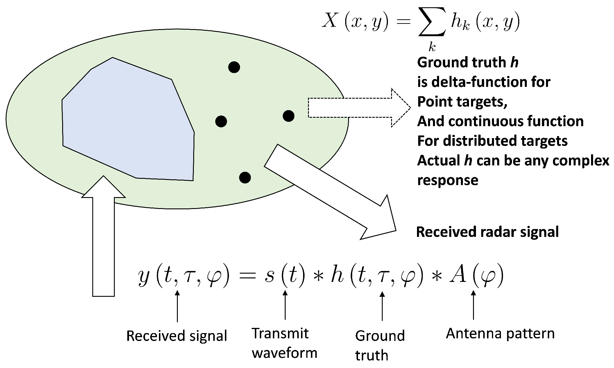
For multiple targets (stationary and moving) and assuming no aliasing is taking place, Equation (1) can be rewritten as [12,13]:
y l = d = 1 D α l , d s ( ω d ) + n = N + 1 n 0 N 1 d = 1 D α l + n , d J n s ( ω d ) + ϵ l
where s ( ω ) = [ s 0 , s 1 e j ω , , s N 1 e j ( N 1 ) ω ] T is the transmit waveform. Here, α l , d denotes the complex RCS for the l-th range bin and the d-th Doppler bin. There are a total of L range bins and D Doppler bins. The matrix J n is of the form:
J n = 0 1 0 0 1 0 0 0
and is a square matrix of size N. J n has one in the n-th sub-diagonal and zeroes elsewhere. J 0 = I , J n = J n T and J n = 0 for | n | N . The N continuous returned signal for the l-th range bin from the p-th pulse can be written as:
y l ( p ) = n = N + 1 N 1 d = 1 D α l + n , d e j ( p 1 ) T r ω d J n s ( ω d ) + ϵ l ( p )
where T r is the pulse repetition time divided by the duration of a single sub-pulse (numbers of sub-pulses within one pulse repetition time (PRT)). If the returns from the pulses y l ( p ) , 1 p P are stacked on top of each other, the returns take the form [13]:
y l = n = N + 1 N 1 d = 1 D α l + n , d p ( ω d ) ( J n s ( ω d ) ) + ϵ l
where y l = [ y l T ( 1 ) , , y l T ( P ) ] T , ⊗ is the Kronecker matrix product, and p ( ω ) = [ 1 , e j T r ω , , e j ( P 1 ) T r ω ] T
The matched filter response takes the form:
x ^ l = s H y l = n = N + 1 K l N 1 + K r d = 1 D α l + n , d p ( ω d ) ( J n s ˜ ( ω d ) ) + s H ϵ l
where,
s ˜ k ( ω ) = n = N + 1 K l N 1 + K r s n H s n k ( ω ) k = N + 1 K l , , 0 , , N + 1 + K r
Note, J n here is a square matrix of size 2 N + K l + K r that has ones in the n-th sub-diagonal and zeroes elsewhere. If we let f n ( ω d ) = p ( ω d ) ( J n s ˜ ( ω d ) ) and s H ϵ l = ϵ , then we can write Equation (7) as:
x ^ l = n = N + 1 K l N 1 + K r d = 1 D α l + n , d f n ( ω d ) + ϵ
Equation (9) can be solved by applying the IAA algorithm [14]. The estimate at the i-th iteration is:
α ^ l , d ( i ) = f 0 H R ( i 1 ) 1 ( l ) x ^ l f 0 H R ( i 1 ) 1 ( l ) f 0
and,
R ( i 1 ) ( l ) = n = N + 1 K l N 1 + K r d = 1 D | α l + n , d | 2 f n ( ω d ) f n H ( ω d )
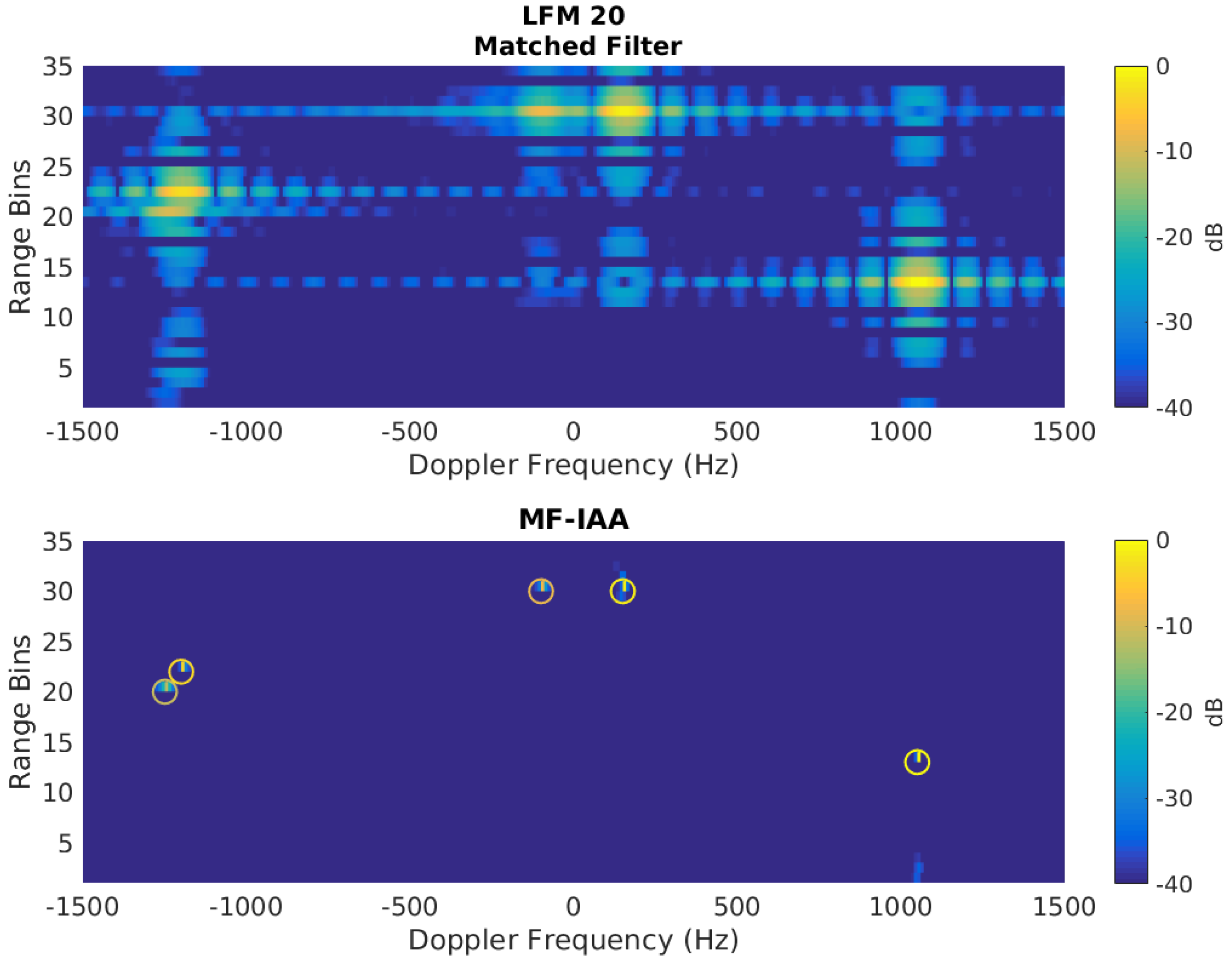
Matched filter returns are simulated to study the performance of MF-IAA. The simulated scene comprises five targets at varying ranges and Doppler frequencies. The truth for simulation is tabulated in Table 2. For the simulation, 60 pulses are transmitted with a PRF of 6 kHz. Each pulse is a 10- μ s linear frequency modulated (LFM) pulse with an 8-MHz bandwidth. The Doppler resolution for the matched filter-based range-Doppler image (RDI) is 100 Hz. The MF-IAA algorithm is applied to enhance the resolution by a factor of 10. Figure 8 shows a comparison between RDI obtained from the matched filter outputs and MF-IAA outputs. If we look at the RDI from the matched filter (top section of the Figure 8), there is no proper distinction of all five targets. The range and Doppler sidelobes have significantly masked nearby targets. There is no distinction between the return from a weaker target and the sidelobes of a stronger target. The bottom section of Figure 8 shows the RDI obtained from MF-IAA outputs. The center of the circles in the figure represent the location of the ground truth, and the color of circles represents the target SNR. In MF-IAA RDI, a clear distinction between the five targets in the scene can be easily observed. In addition to removing range sidelobes, most of the Doppler sidelobes are also suppressed. The estimation of target SNR also resembles the ground truth.
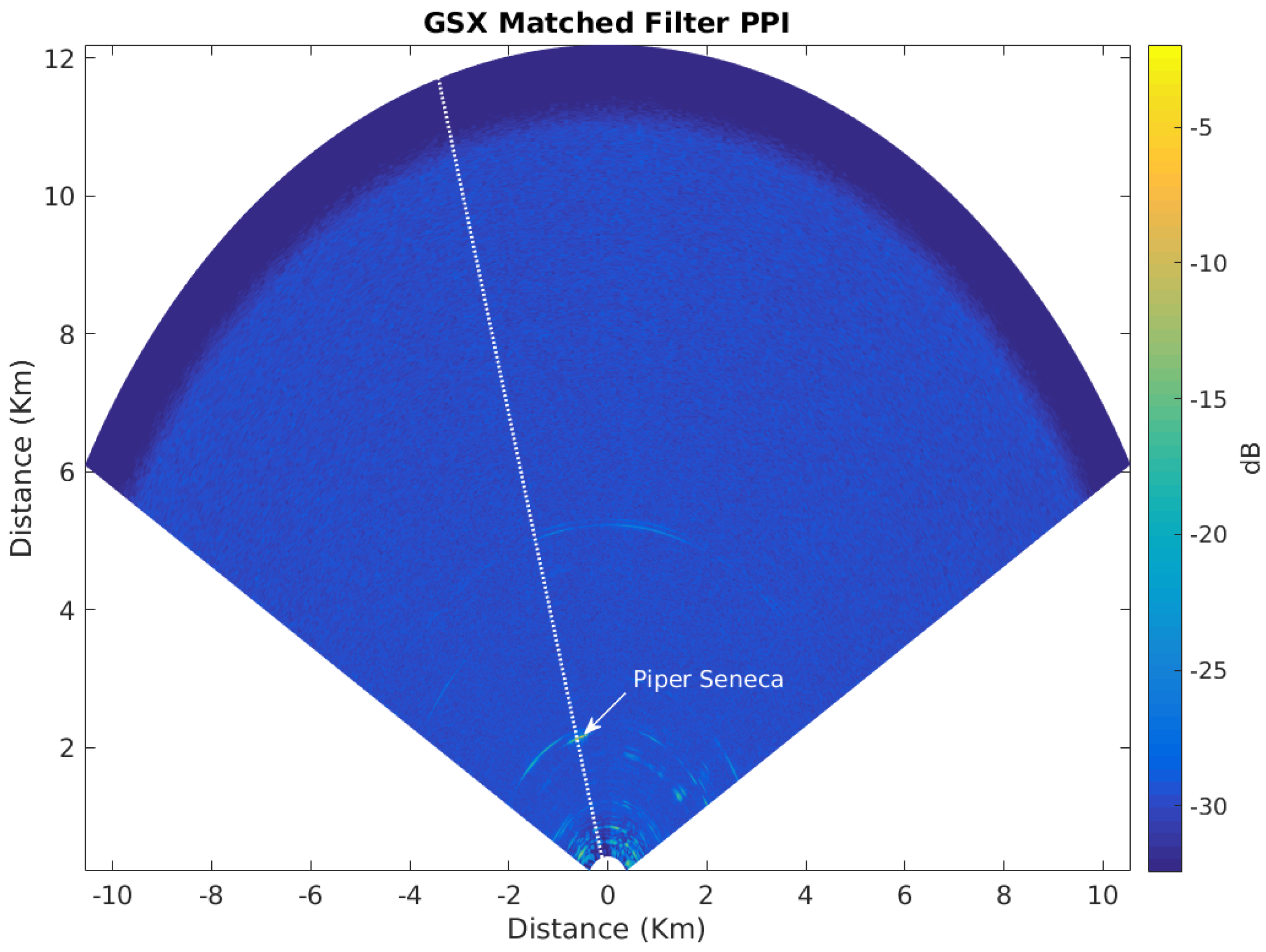
The performance of MF-IAA was also evaluated for a measured target. A twin-engined light aircraft (Piper Seneca) was flown in a predetermined path, and returns from PARADOX1 were collected. As in the simulated case, the range-Doppler image was created using matched filter outputs, which were compared with MF-IAA outputs. Figure 9 shows the planned position indicator (PPI) output directly from PARADOX1. A single range profile (shown in the white dotted line) was extracted to generate the range-Doppler image. The Coherent Pulse Interval (CPI) consists of 20 pulses at 5 kHz PRF, resulting in a Doppler resolution of 250 Hz. Each pulse was 6.83 μ 
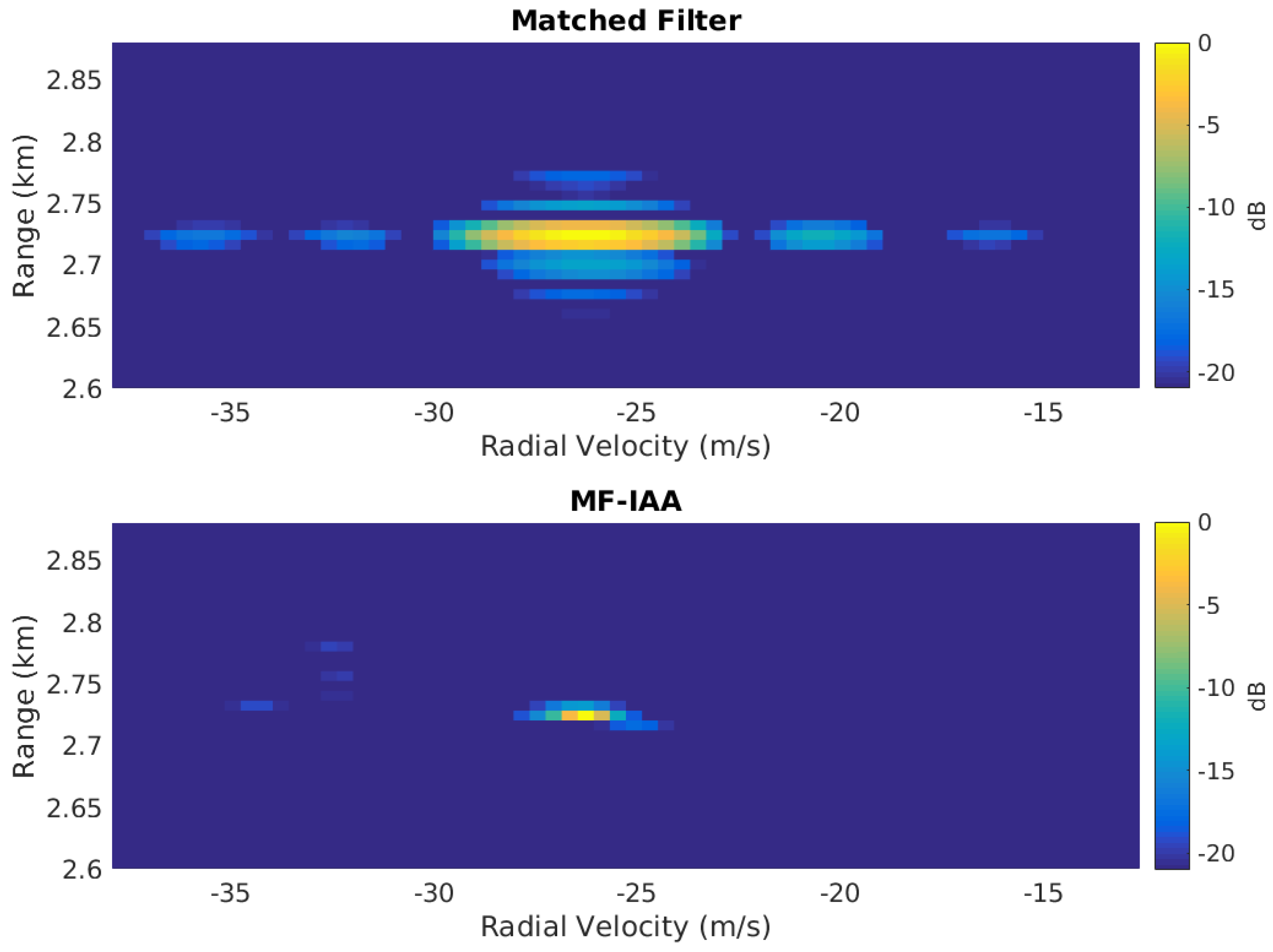
s with a bandwidth of 9.375 MHz. Again, MF-IAA was used to enhance the Doppler resolution by a factor of 10, thereby making the effective resolution 25 Hz. The results are presented in Figure 10 where the RDI from matched filter outputs is on the top and the IAA output is on the bottom. Although the Doppler estimation is not as precise as in the simulation case, there is a clear enhancement from MF-IAA when compared with RDI from the matched filter results. The range sidelobes are virtually eliminated, while in the case of Doppler, there is some spread of the target itself. This is due to the low number of pulses or a poor starting Doppler frequency resolution. Besides the main lobe spread, there are no Doppler sidelobes in the MF-IAA case. It can be argued that in the case of the availability of more pulses, the Doppler resolution can be further enhanced to produce a “single-pixel” result as in the case of simulated data.

5. Multi-Target Tracking for DAA

As previously mentioned, the basic DAA tracking function is implemented through track while scan (TWS) mode. The Kalman filter (KF) is used for estimating the state of dynamic targets while joint probabilistic data association (JPDA) is used to associate the measurements to tracks. The Kalman filter [15] provides a recursive method to optimally estimate the state of linear systems in the presence of Gaussian error statistics. JPDA provides joint posterior association probabilities for multiple targets in the presence of Poisson clutter [16]. KF and JPDA together form the tracking backend of the DAA tracker. Although other state estimation algorithms (e.g., extended Kalman filter, particle filter, etc.) and data association algorithms (e.g., global nearest neighbor, multiple hypothesis tracking, etc.) are available, KF and JPDA are used primarily because of good results with a smaller computational requirement. A “g-sigma ellipsoid” gating is used to reject measurements for each track, which further increases the computational speed. 
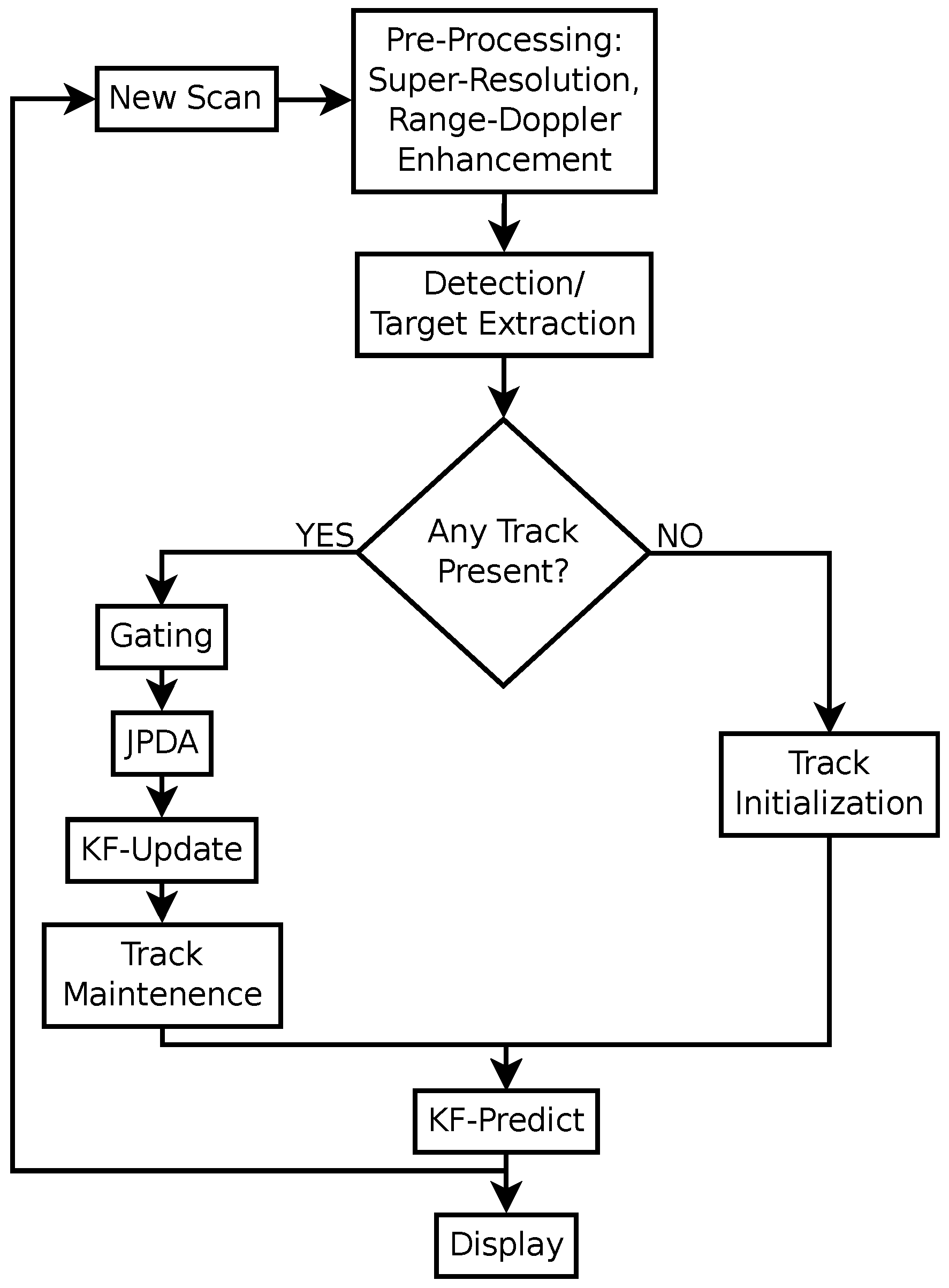
Figure 11 shows the DAA tracker algorithm flow. Note that the “track maintenance” step adds and deletes track as necessary. A tentative track is added when a new target is not associated with any existing tracks. An existing track is deleted if no measurements are associated for a that track during multiple consecutive scans.

Simulated Multi-Target DAA Scenario

Since we did not have the opportunity to use multiple aircraft in the flight test, a two-target scenario is simulated using MATLAB and Phased Array System Toolbox Release 2016b, The MathWorks Inc., Natick, MA, USA. The simulation parameters are chosen to match the specifications of PARADOX1 as described in Table 1 except for the antenna. The antenna used for simulation is a phased array antenna with 4.5 azimuth beamwidth and 90 elevation beamwidth. There are two closely moving targets in the simulation scene. The motion model used is a constant acceleration model where noise is modeled as perturbations in acceleration. The noise model is a Gaussian random variable with zero mean and a standard deviation of 6 m/s 2 in the range direction and 2 m/s 2 
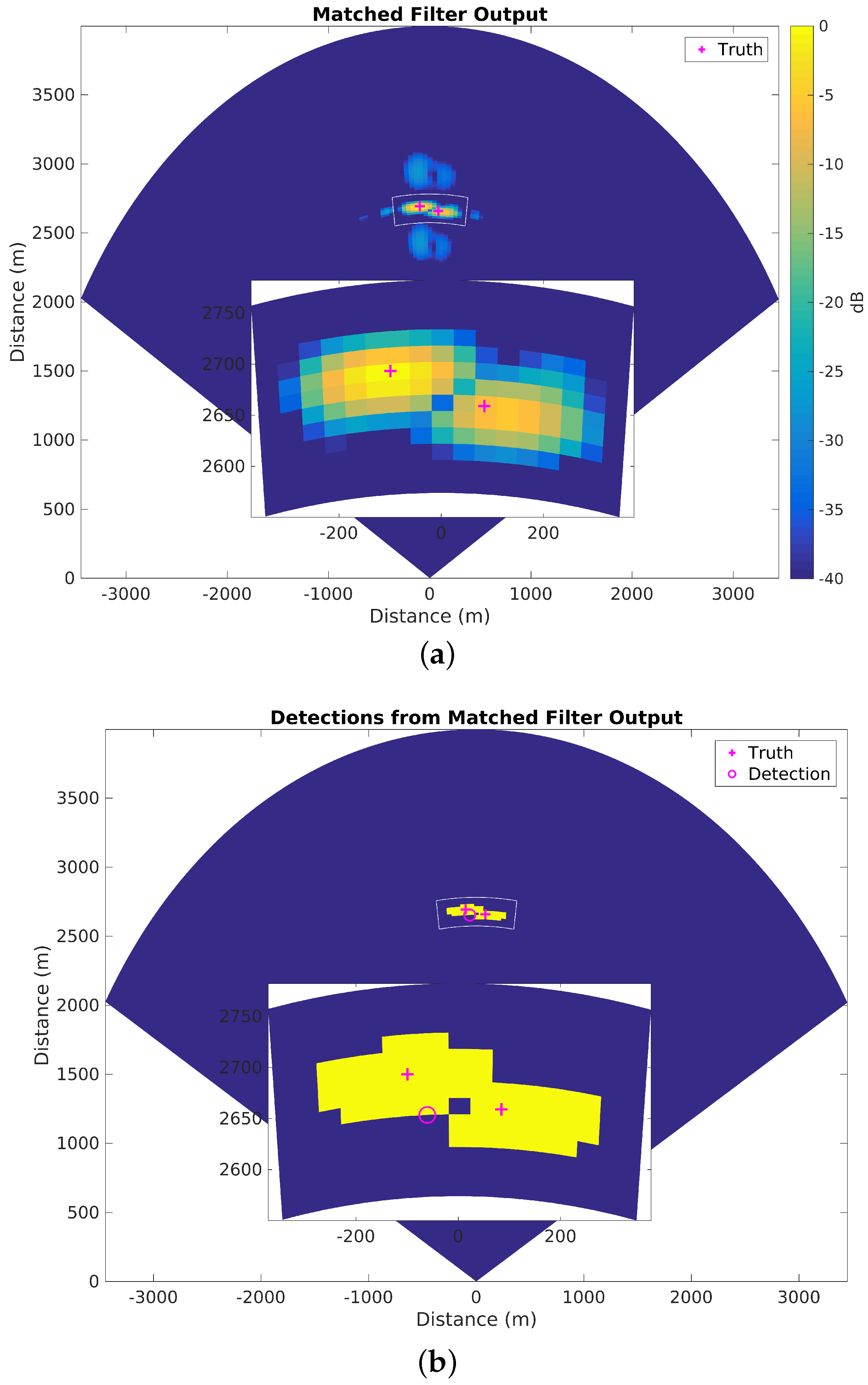
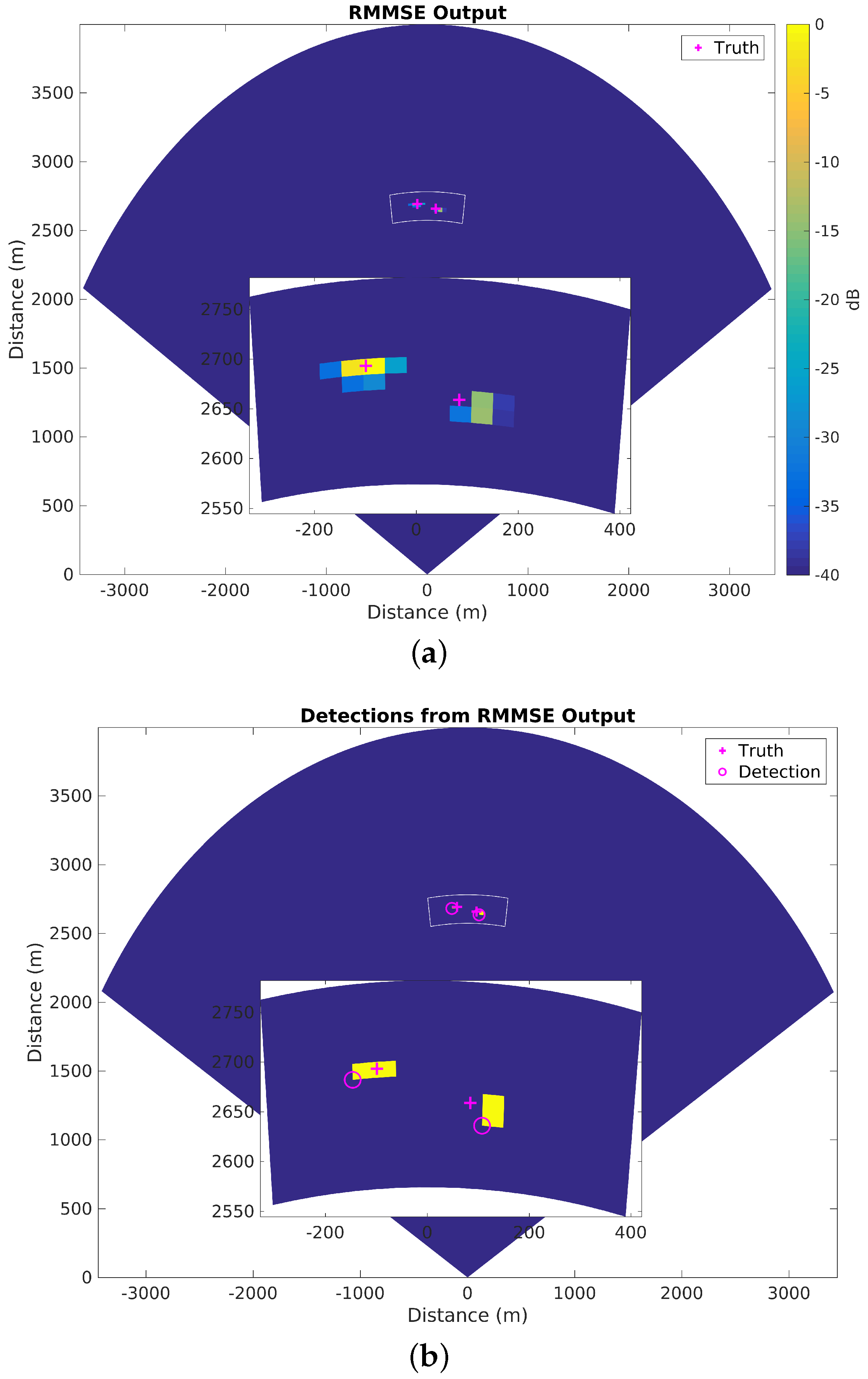
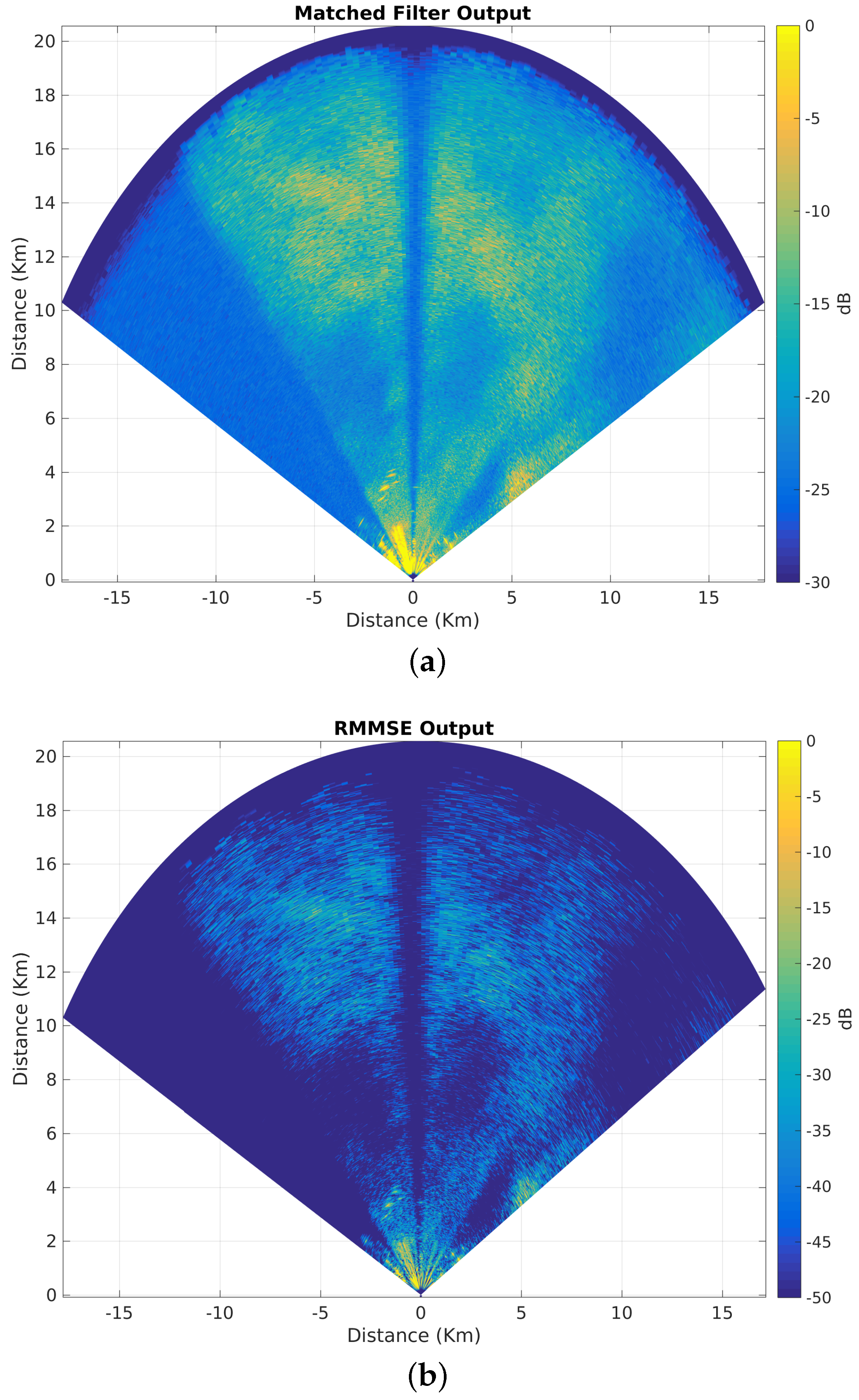
in the cross-range direction. A snapshot of matched filter output and its resulting detection, as well as RMMSE super-resolution algorithm output and its resulting detection is shown in Figure 5a,b and Figure 6a,b, respectively. These results are discussed in Section 3.2. In this section, the tracking performance before and after RMMSE super-resolution algorithm will be discussed. The RMMSE-SR algorithm is used in this case (as opposed to IAA) primarily because the two targets are in separate azimuth angles. The IAA algorithm is used in cases where there are multiple targets in the same azimuth angle (same range profile), but with different yet unresolvable Doppler frequencies.
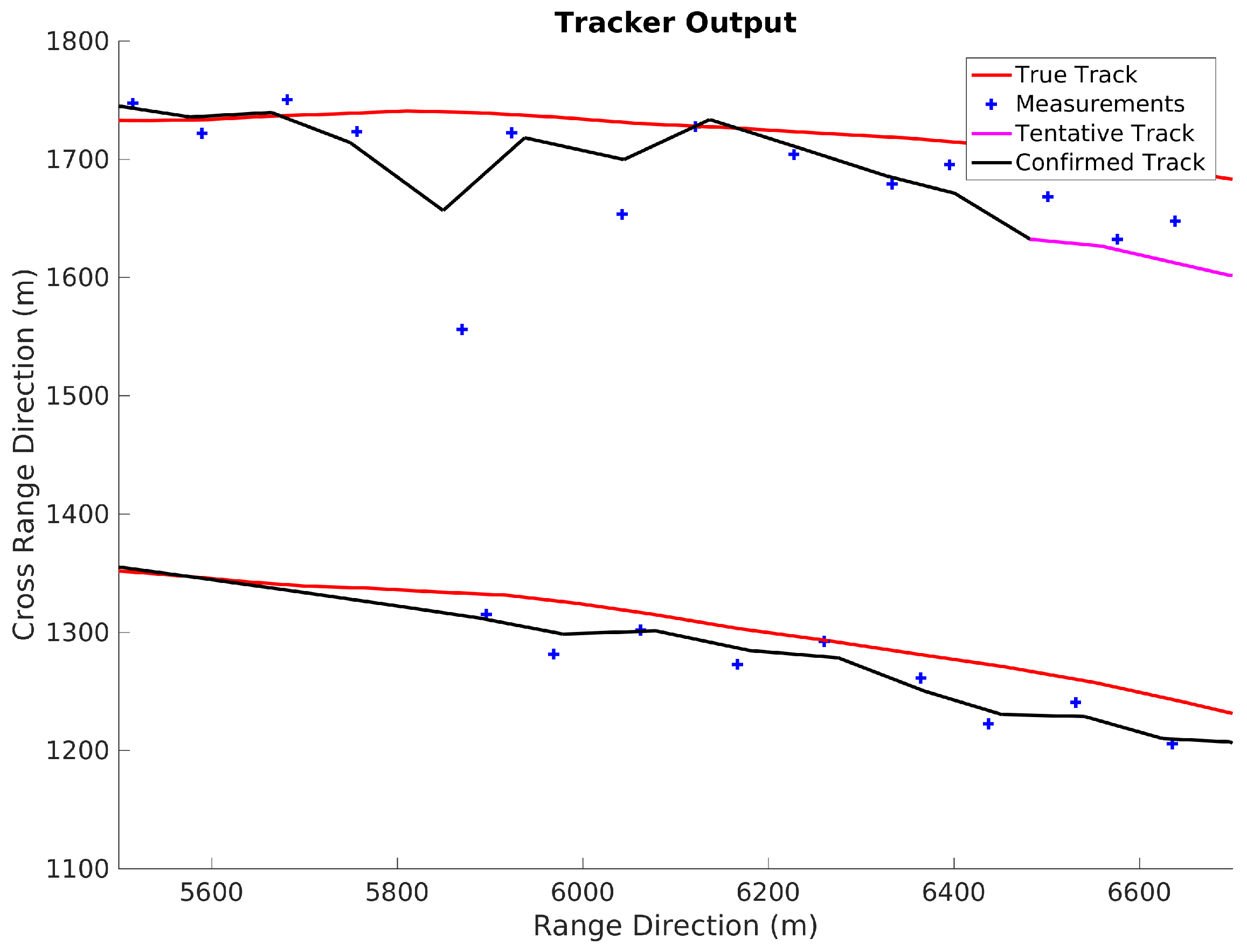
Figure 12 and Figure 13 show the tracking results with matched filter-based detections and RMMSE-SR-based detections, respectively. Matched filter output does not resolve the two targets adequately, which results in a single track positioned between the two true tracks. The detections are spread out as the radar cross-section (RCS) of the targets vary from scan to scan. In some cases, sidelobes from a stronger target also register as detections. The detections are in the middle of two tracks because the azimuth resolution is low, which results in a single lumped large target to be formed in the binary image. The detection point then would be the center of mass of that lumped large target as discussed in Section 3 and depicted in Figure 5a,b. Since a simple threshold detector is used, the tradeoff between having the ability to detect smaller targets (by setting a lower threshold) and preventing sidelobes registering as targets (by setting a higher threshold) becomes more consequential. In the case of RMMSE-SR-based detection and tracking, two tracks are clearly visible. Although there are few detections away from the truth (higher measurement noise), most of the detections are close to the truth and so is the formed track. The data are generated from simulation, and the measurement noise is assumed to be zero. The deviation of measurements from the truth data can be caused by fluctuations in RCS and limited angular resolution. In the RMMSE case (Figure 13), there is a loss of detection (lower track left side), but the tracker continues to perform without significant degradation. The track updates when the next measurement falls inside the gate (of the predicted position).

6. Ground-Test Experiments and Results

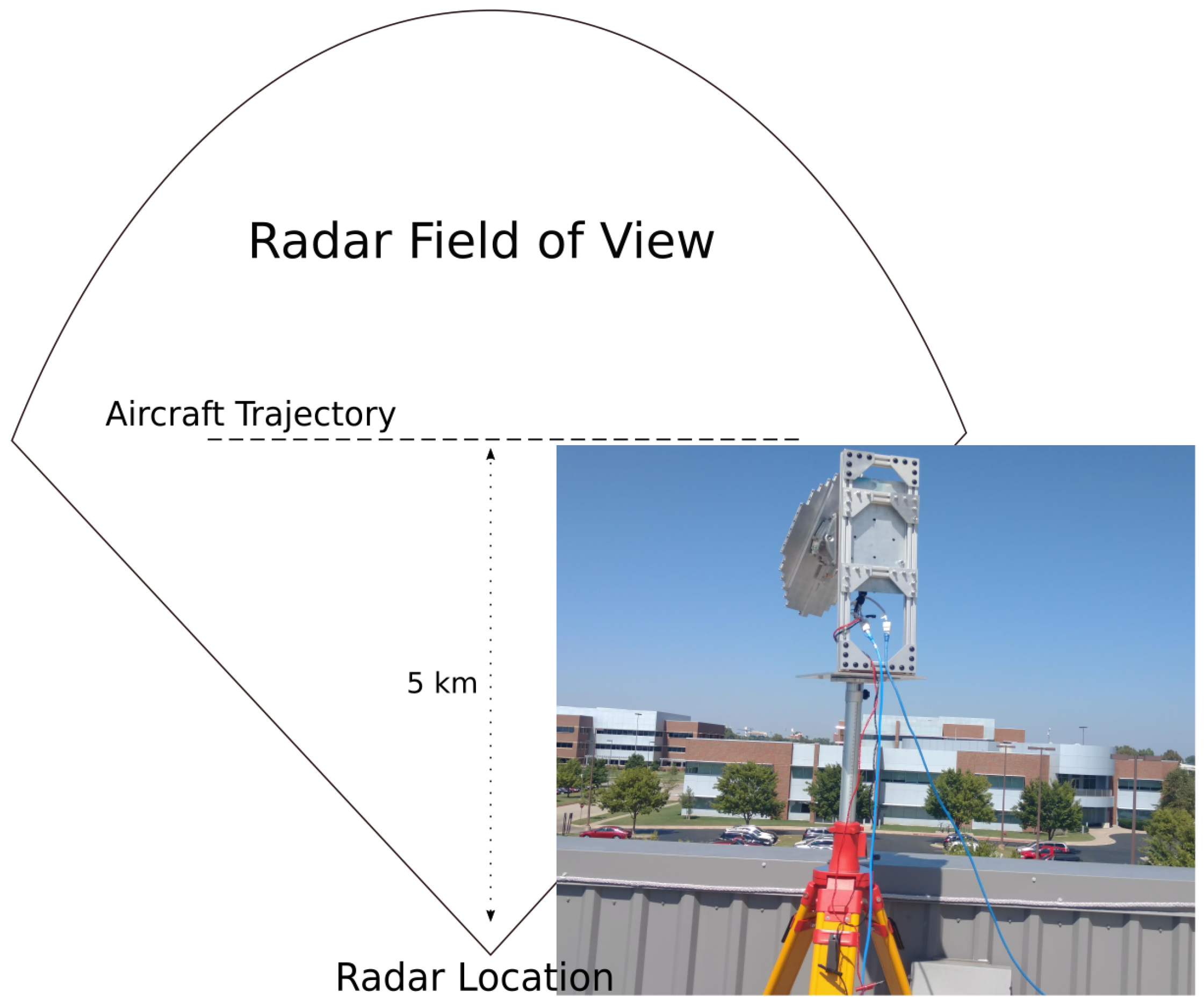
A ground test experiment was conducted to demonstrate the feasibility of real-time tracking using PARADOX1/GSX radar. As previously mentioned, tracking is done in track while scan (TWS) mode. For this ground test, the radar was placed at the roof of a two-story building while a small twin engine aircraft was flown in a predetermined path. A sketch of the flight trajectory and radar location in addition to a picture of the PARADOX1 setup is depicted in Figure 14. The required elevation angle of the radar was designed to be sufficiently high to eliminate ground clutter returns, which more closely mimics the air-to-air tracking scene. In this particular test, the elevation of the radar is kept constant, and the plane is allowed to fly in and out of the beam coverage in elevation. Note that for an airborne collision avoidance operation, the elevation angle of the radar platform may be changed between scans. Collision threats that are flying in a constant altitude would then be in and out of the beam coverage in elevation similar to the current ground test setup. However, the most compelling scenario is when the collision threat is located in the same horizontal plane (thus at zero elevation) of the radar platform. For such a case, measurement data points will increase due to better scan coverage, which then results in improved tracking performance when compared to the current setup of ground experiment. In this setup, the speed of the airplane is maintained around 55 m/s (with some fluctuations caused by the wind, pilot control/maneuvering, etc.), and the radar scan update time is about 2.5 s.
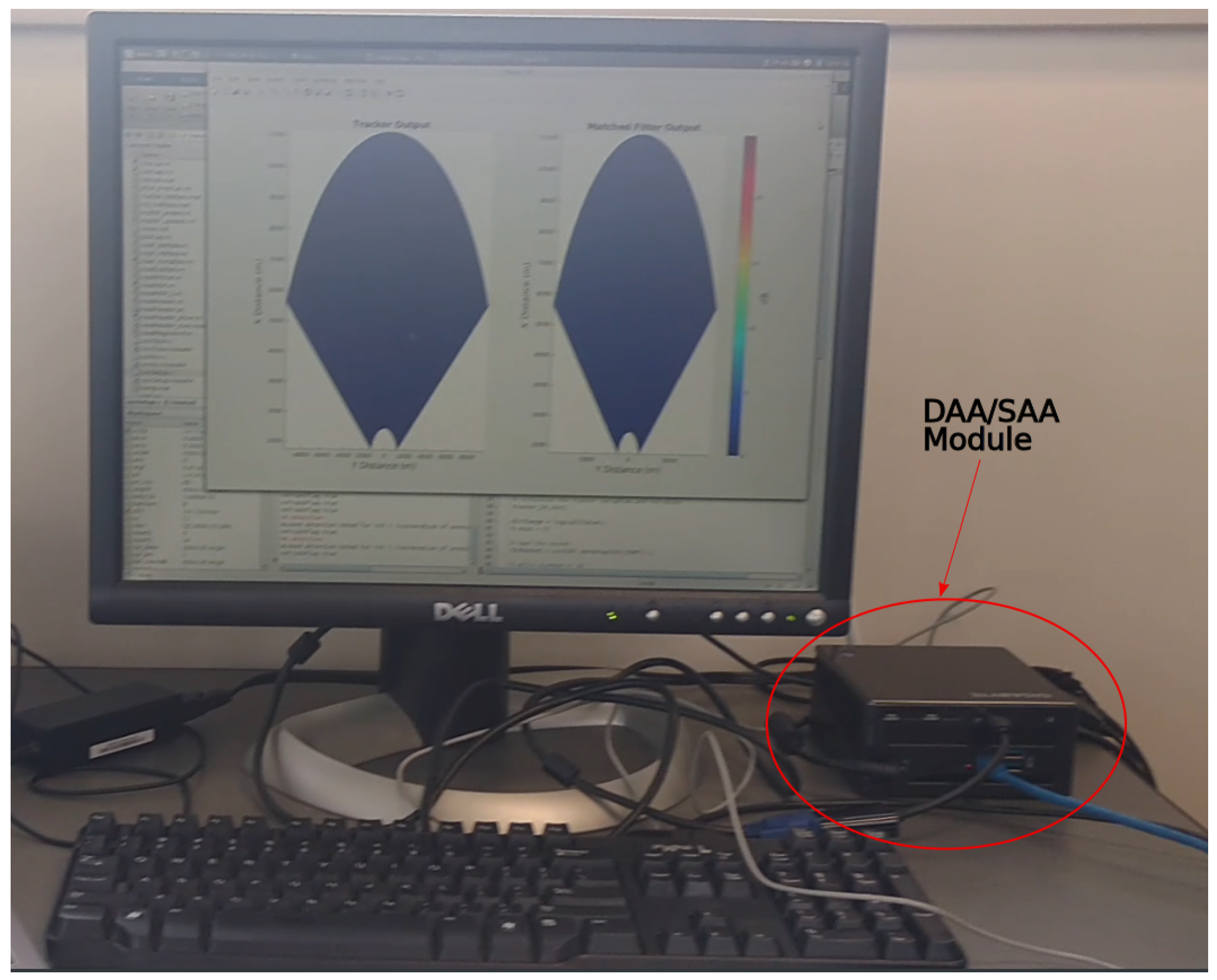
The module used for DAA/SAA tracking consists of a small form factor PC with Intel© Core i7 processor from Intel Corporation, 2200 Mission College Blvd., Santa Clara, CA, USA and 16 GB of DDR3 random access memory (RAM). The module runs a generic GNU/Linux Operating System. Data from the radar sensor are fed into the module using the gigabit speed Ethernet port, which is read and processed by MATLAB® using various functions written in C Programming Language. The output to a connected monitor is the PPI of the current scan and tracks resulting from previous scans. In our tests, this hardware is adequate to perform DAA/SAA tracking between each scan update time of about 2.5 s. Figure 15 shows the module for DAA/SAA tracking.
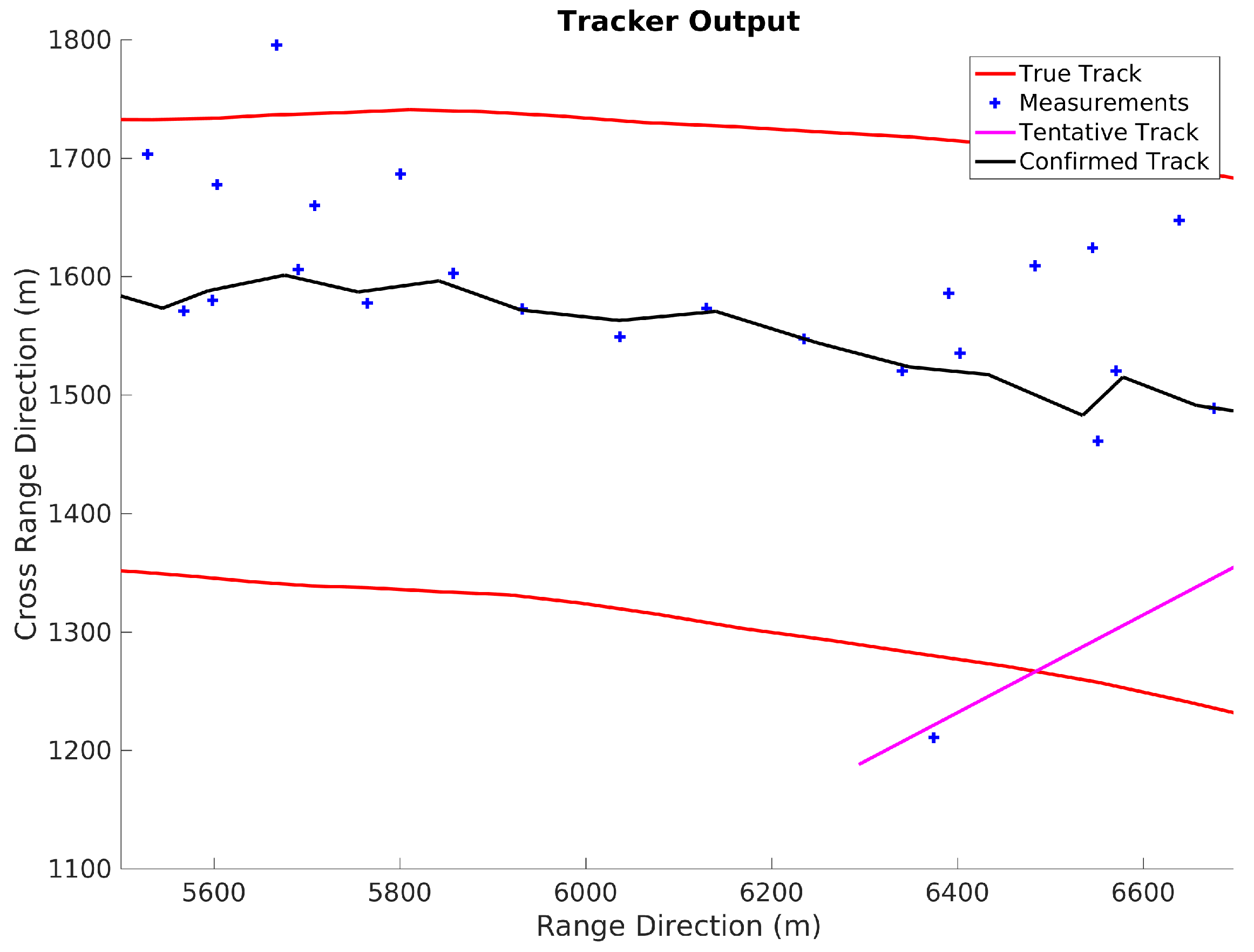
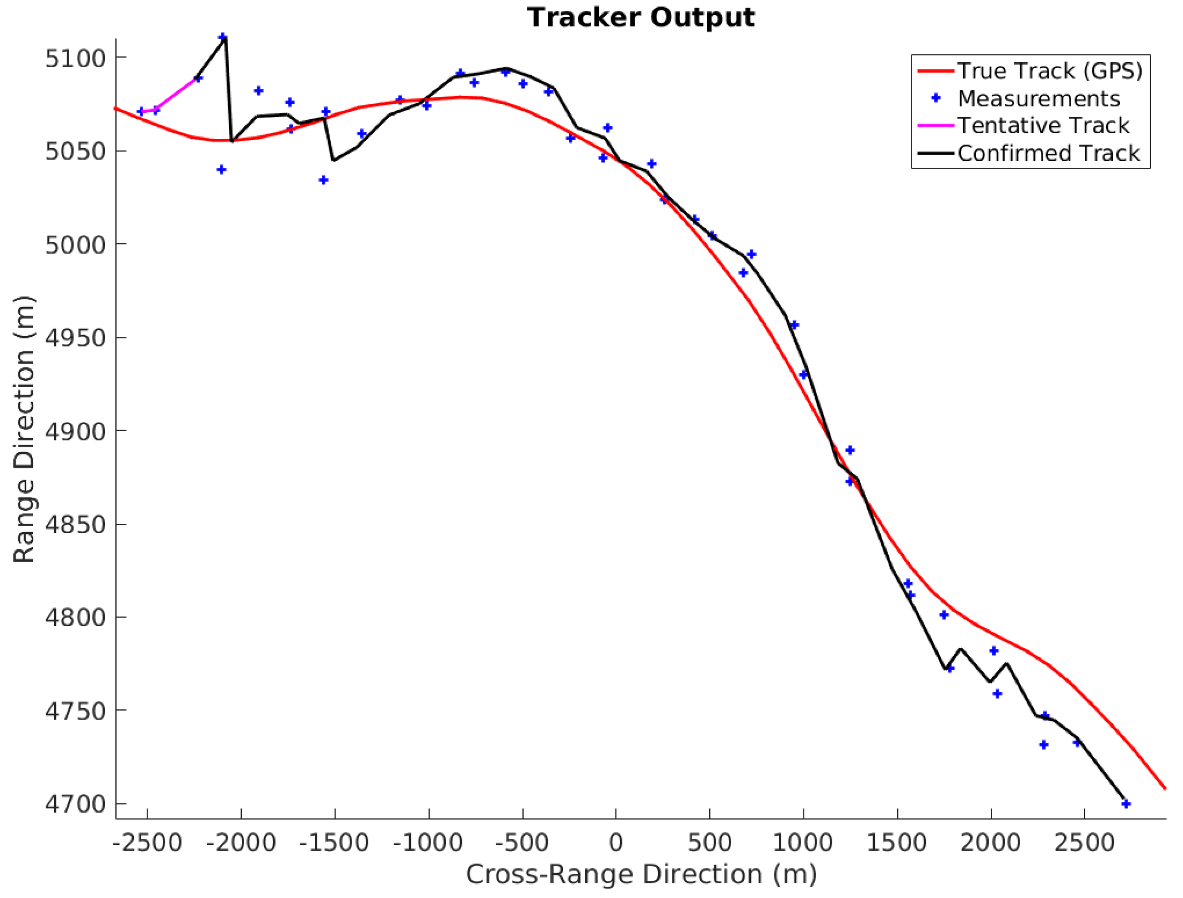
Figure 16 shows a sample tracking result for the current ground tracking test. The figure clearly depicts a confirmed track around the measurement points. The measurements are scattered around the ground truth (as opposed to be coincident). This is most likely caused by errors in GPS measurements (the plane employs a differential GPS system, which is much more accurate than the one used by the ground-based radar). The update time also plays an important role in the bias of measurements. A faster update time generally means less target movement between scans and consequently less bias. Another potential source of error is the angular resolution limitation, which causes “quantization error” in measurements. The current setup of PARADOX1 has an 18-inch antenna with a beamwidth of 5.6 in both elevation and azimuth.
The performance of the Kalman filter and JPDA-based tracker is adequate in this case. The tracker is able to track the measurements and maintain the track for the duration of target visibility. An error analysis is performed between measured values and truth values, which is presented in Table 3. Although the error in the azimuth direction is expected to be high as it is significantly affected by the azimuthal beam spread, in reality, the values are lower because of the detection procedure (the center of mass of the centroid is assumed to be the measured position). The mean square error in the range dimension is about one range resolution distance, which is acceptable. The maximum error in range is about 43 m, which is due to the unfortunate combination of the radar scan update rate and the plane GPS update rate. In the future, timestamps for each pulse can be noted to decrease this error.

7. Summary and Conclusions

The SAA/DAA function on Garmin’s GWX radar is developed, which is able to perform multi-mission operations, while simultaneously decreasing cost, space, weight and power (C-SWaP). The feasibility of algorithms for DAA/SAA functions is tested both in simulation, as well as a single airborne target case. DAA/SAA tracking is performed using a simple Kalman filter for state estimation/update, while using joint probabilistic data association to associate measurements with tracks. Azimuthal super-resolution is performed using the RMMSE algorithm, and tracking is performed with simulated and real-time measurement data. RMMSE performance is also studied using measured weather data. Range Doppler enhancement using the matched filter-based iterative adaptive approach is discussed in detail. Real-time TWS and its results are discussed. The radar sensor is able to perform well in real-time tracking, while RMMSE/MF-IAA simulation results show the potential for the radar sensor to overcome some of the physical limitations in resolving the targets using advanced software algorithms. A multiple close targets’ (in range/Doppler/azimuth) scene and subsequent super-resolution/tracking studies will be the focus of future work.

Acknowledgments

This research was funded by Oklahoma Center for the Advancement of Science and Technology (OCAST). Grant Number: AR14-016.

Author Contributions

Yan Zhang envisioned the idea of making software enhancement to commercial radar (GWX/GSX product line from Garmin International) thereby achieving SAA/DAA functionalities. The ground test experiments were designed through a series of meetings between Ramesh Nepal, Yan Zhang, and William Blake. William Blake designed optimal configurations of the radar for our tests. Ramesh Nepal and Yan Zhang conducted the tests/experiments. The simulation codes were primarily written by Ramesh Nepal with help from Yan Zhang and William Blake. The codes for recording data from the radar were written by William Blake and modified by Ramesh Nepal to fit the experimental needs. The article was drafted by Ramesh Nepal and Yan Zhang with inputs from William Blake. The subsequent revisions were made by Ramesh Nepal after consulting with Yan Zhang and William Blake.

Conflicts of Interest

The authors declare no conflict of interest.

References

  1. Haessig, D.A.; Ogan, R.T.; Olive, M. “Sense and Avoid”—What’s required for aircraft safety? In Proceedings of the SoutheastCon, Norfolk, VA, USA, 30 March–3 April 2016; pp. 1–8.
  2. Ackerman, E. IEEE Spectrum 2016. Available online: https://goo.gl/gDES9J (accessed on 26 February 2017).
  3. John, J.; Kirchgessner, J.; Ma, R.; Morgan, D.; Trivedi, V. Si-Based Technologies for mmWave Automotive Radar. In Proceedings of the Compound Semiconductor Integrated Circuit Symposium (CSICS), Austin, TX, USA, 23–26 October 2016; pp. 1–4.
  4. GWX™ 70. Available online: https://goo.gl/VcpfLk (accessed on 4 December 2016).
  5. Garmin Brings Affordable Doppler-Capable Weather Radar Capabilities to General Aviation with GWX™ 70. Available online: https://goo.gl/lXwyoO (accessed on 4 December 2016).
  6. Fasano, G.; Accado, D.; Moccia, A.; Moroney, D. Sense and avoid for unmanned aircraft systems. IEEE Aerosp. Electron. Syst. Mag. 2016, 31, 82–110. [Google Scholar] [CrossRef]
  7. RTCA subcommittee 228, Washington, DC, USA. Minimum Operational Performance Standards (MOPS) for Air-to-Air Radar for Detect and Avoid Systems DRAFT. Unpublished work. August 2016.
  8. Due Regard Radar. Available online: https://goo.gl/8xKi1v (accessed on 8 February 2017).
  9. Accardo, D.; Fasano, G.; Forlenza, L.; Moccia, A.; Rispoli, A. Flight Test of a Radar-Based Tracking System for UAS Sense and Avoid. IEEE Trans. Aerosp. Electron. Syst. 2013, 49, 1139–1160. [Google Scholar] [CrossRef]
  10. Wang, S.; Li, Z.; Zhang, Y.; Cheong, B.; Li, L. Implementation of Adaptive Pulse Compression in Solid-State Radars: Practical Considerations. IEEE Geosci. Remote Sens. Lett. 2015, 12, 2170–2174. [Google Scholar] [CrossRef]
  11. Blunt, S.D.; Gerlach, K. Adaptive pulse compression via MMSE estimation. IEEE Trans. Aerosp. Electron. Syst. 2006, 42, 572–584. [Google Scholar] [CrossRef]
  12. Nepal, R.; Zhang, Y.R.; Li, Z.; Blake, W. Matched Filter Based Iterative Adaptive Approach. In Proceedings of the SPIE Defense + Commercial Sensing Conference on Radar Sensor Technology XX, Baltimore, MD, USA, 17–21 April 2016; p. 982912.
  13. Tan, X.; Roberts, W.; Li, J.; Stoica, P. Range-Doppler imaging via a train of probing pulses. IEEE Trans. Signal Process. 2009, 57, 1084–1097. [Google Scholar]
  14. Yardibi, T.; Li, J.; Stoica, P.; Xue, M.; Baggeroer, A. Source Localization and Sensing: A Nonparametric Iterative Adaptive Approach Based on Weighted Least Squares. IEEE Trans. Aerosp. Electron. Syst. 2010, 46, 425–443. [Google Scholar] [CrossRef]
  15. Kalman, R.E. A new approach to linear filtering and prediction problems. J. Basic Eng. 1960, 82, 35–45. [Google Scholar] [CrossRef]
  16. Fortmann, T.; Bar-Shalom, Y.; Scheffe, M. Sonar tracking of multiple targets using joint probabilistic data association. IEEE J. Ocean. Eng. 1983, 8, 173–184. [Google Scholar] [CrossRef]
Figure 1. Polarimetric airborne radar operating at X-band—Generation 1 (PARADOX1): A multi-mission radar.
Aerospace 04 00011 g001
Figure 2. Configuration of the airborne radar test system.
Aerospace 04 00011 g002
Figure 3. Diagram summary of the processing flow executed in the DAA processor.
Aerospace 04 00011 g003
Figure 4. Concept of using the radar probing waveform to retrieve the most “truthful” information about the target of interest; reprinted from [12].
Aerospace 04 00011 g004
Figure 5. Matched filter output and resulting detection. (a) Matched filter output for two close targets; (b) Detections resulting from matched filter outputs.
Aerospace 04 00011 g005
Figure 6. Reiterated minimum mean square error (RMMSE)-super-resolution (SR) output and resulting detection. (a) RMMSE super-resolution algorithm output; (b) Detections resulting from the super-resolution algorithm output.
Aerospace 04 00011 g006
Figure 7. Matched filter and SR output for distributed weather target. (a) Matched filter output; (b) RMMSE super-resolution algorithm output.
Aerospace 04 00011 g007
Figure 8. Simulated range-Doppler image produced using matched filter output (top) and matched filter-based iterative adaptive approach (MF-IAA) output (bottom).
Aerospace 04 00011 g008
Figure 9. PPIoutput from GSXradar for a scene containing an airborne target. The dotted white line represents the azimuth where range-Doppler processing is done.
Aerospace 04 00011 g009
Figure 10. Comparison of the range-Doppler image from matched filter output and MF-IAA output for a scene with an airborne target (Piper Seneca).
Aerospace 04 00011 g010
Figure 11. Tracking flowchart.
Aerospace 04 00011 g011
Figure 12. Tracking results with matched filter-based detections.
Aerospace 04 00011 g012
Figure 13. Tracking results with RMMSE-based detections.
Aerospace 04 00011 g013
Figure 14. Real-time ground tracking flight trajectory.
Aerospace 04 00011 g014
Figure 15. Real-time ground tracking module.
Aerospace 04 00011 g015
Figure 16. Real-time ground tracking results.
Aerospace 04 00011 g016
Table 1. PARADOX1 specifications.
Radar Parameters Values
Mechanical DimensionsAntenna Size10–18 inches for standard antenna product configuration
Transceiver Diameter8 inches
Depth6.3 inches
Total Weight9.5 lbs (for an 18-inch antenna and electronics) plus digital backend (small form factor PC)
Operating Frequency9.3 to 9.5 GHz
AntennaSlotted Waveguide Array and Mechanical Scanning
FOV ± 60 azimuth, ± 30 elevation
TransmitterSolid-state 40 watt peak power, support for a wide range of waveforms and Pules Repetition Frequency (PRF)
Sensitivity0 dBZ (reflectivity factor in decibels) at 30 km
ReceiverReal-time pulse compression receiver with optimized Linear Frequency Modulated (LFM) and phase coded waveforms
Antenna BeamwidthScalable: 18-inch panel: 5.6 in both azimuth & elevation
Scan SpeedVariable (depends on the number of transmitted pulses)
Basic Data ProductsReal-time: reflectivity, Doppler velocity, spectrum width; off-line: SAR (synthetic aperture radar) imaging, airborne hazard and biological target trajectory estimation
Mounting and InstallationNose cone mounting or pod mounting
Table 2. Simulation target truth.
Target NumberTarget Range BinTarget DopplerTarget Power (dB)
113105023
220−125012
322−120020
43015022
530−10015
Table 3. Measurement error statistics for PARADOX1 during the ground test.
StatisticRange Direction (m)Azimuth Direction ( )
Maximum Square Error43.62.07
Minimum Square Error0.530
Mean Square Error16.460.76
Standard Deviation of Square Error19.870.95

