1. Introduction
There are some aero-elastic flutter and vibration research articles of beams, shells, and plates. Samadpour et al. [
1] investigated the supersonic flutter of composite beams with shape memory alloys (SMA) under thermal and aerodynamic loads, the aero-thermal flutter characteristics can be enhanced by embedding with SMA fibers in the laminated beam. Liu et al. [
2] investigated the effects of supersonic aerodynamic and thermal loads on functionally-graded material (FGM) cylindrical shells, the results of nonlinear dynamics responses are obtained. Li and Narita [
3] presented the optimal design in flutter analysis of supersonic flow over doubly-curved shallow laminated shells by using MATLAB code, the optimal fiber orientation angles are obtained. Alijani and Amabili [
4] presented the reviewing 2003–2013 papers of vibration shells included the effects of fluid–structure interactions and thermal loads, non-linear vibrations of shells are addressed. Amabili et al. [
5] used Donnell’s non-linear geometric shallow shell theory to investigate the dynamics and stability for a very thin, circular cylindrical shell within internal water flow, a complex dynamical behavior is obtained. Kiiko [
6] studied the vibration of a shallow cylindrical shell in a supersonic gas flow, the well-known formula of “piston” theory is used as a compressive force. There are some recently published research of the subject of the effects of shear deformation theory on the displacements of FGM plates and shells. Yin et al. [
7] used higher-order shear deformation theory (HSDT) to investigate the buckling loads and natural eigenvalues of FGM plates, for considering shear deformation effect without requiring any shear correction factors. Bui et al. [
8] used the third-order shear deformation theory (TSDT) to investigate the static bending deflections and natural frequencies of FGM plates, also without requiring any shear correction factors. Sun et al. [
9] used Donnell’s shell theory in the deflection and the lower-order Hamiltonian canonical equations in the fundamental buckling equations to investigate the critical loads and buckling modes of the FGM shells under thermal environment, the mixtures of Si
3N
4/SUS304 and Al
2O
3/SUS304 materials are studied. Yin et al. [
10] used first-order shear deformation theory (FSDT) to investigate the static bending, buckling, and the free vibration of FGM plates, numerical results with the effects of boundary conditions, gradient index, and geometric shape are presented.
There are some works based on Carrera unified formulation (CUF) for the technical models and analyses in the non-linear displacement fields. Ramos et al. [
11] used a unified new trigonometric displacement field expansion under CUF to investigate the static problem of laminated plates under thermal loads, the stress results including the effects of shear deformation are obtained and compared. Mantari et al. [
12] used new non-polynomial displacement fields via CUF to investigate static problem of FGM plates, the static bending results with the effects of trigonometric, exponential and hyperbolic displacement fields are presented. There are some technical contents of generalized differential quadrature (GDQ) computation in the composited shells and plates. Hong [
13] used the GDQ method to compute the time responses of displacements and stresses for composite magnetostrictive shells under rapid heating without considering the shear deformation effects. Hong [
14] also used the GDQ method to investigate the time responses of displacements and stresses for magnetostrictive FGM plates under rapid heating with considering the FSDT effects. Ferreira et al. [
15] used the Carrera unified formulation and the GDQ technique to compute the better solutions of static deformations and free vibration for thick isotropic and cross-ply laminated plates. Hong [
16] presented the thermal vibrations of Terfenol-D FGM plates including the effects of FSDT model and varied values of modified shear correction factor. Hong [
17] studied the thermal vibration of Terfenol-D FGM circular cylindrical shells under rapid heating without considering the effects of shear deformations. The non-linear coefficient term of the displacement field, e.g., TSDT, can be used to derive the equations of motion for thermal vibration of FGM when using a higher-order shell theory. Basically, it is interesting in the linear FSDT with the varied value effects of shear correction coefficients on air flow over the outer surface of FGM thick circular cylindrical shells under four simply supported edges, that the thermal stresses and center deflection of GDQ computational results for supersonic air flow are obtained. Two parametric effects of environmental temperature and FGM power law index on the thermal stress and center deflection of supersonic air flow over the outer surface of FGM thick circular cylindrical shells are also obtained. The advantages and disadvantages of the proposed GDQ approach compared with other existing methods are highlighted, the use of varied values for shear correction coefficients seem better than a constant shear correction value; also, the GDQ computation time is less, and some physical meanings of aero-elastic flutter and vibration research needed to be studied in the future.
The morphing aircraft (adaptive structures and smart materials) theme is one of recent advances in smart structures and multifunctional materials that has facilitated many novel aerospace technologies. Ajaj et al. [
18] presented a new design philosophy for morphing aircraft technology to classify the functionality, operation, and structural layout. Additionally, the performance comparisons between morphing aircraft and conventional aircraft are provided and the morphing parameters would be improved in the future work. Hu et al. [
19] presented and simulated the aero-elastic responses of the folding wing during its morphing processes, and the dynamic aero-elastic stabilities were also investigated in the folding and unfolding rates. Huang and Qiu [
20] presented the numerical results of transient and flutter characteristics in a variable span morphing wing, and found the morphing technology would be used to enhance flight quality for the flutter control. Barbarino et al. [
21] presented a reviewing for the morphing aircraft and focused on structural, shape-changing morphing concepts in the active systems. The morphing aircraft also has optimal aerodynamic characteristics and fuel condition for expanding the entire flight envelope within its safe performance limits. Weisshaar [
22] presented the new shape changes technology in wing surface area and controlled airfoil camber for morphing aircraft design to provide high performance. Librescu et al. [
23] presented and implemented the combined control law of active aero-elastic control in 2-D wing-flap systems to suppress the flutter instability. In this paper, the FGM shell might be embedded with magnetostrictive material to work as the adaptive structures; the maximum flutter value of center deflection amplitude with magnetostrictive FGM shell might be predicted and controlled into smaller value in supersonic air flow. The aero-elastic flutter and thermal vibration researches of magnetostrictive FGM shells might be the potential areas of application on a morphing aircraft to obtain better performances and good structures. In future works, the magnetostrictive material might be embedded in the FGM thick circular cylindrical shells and used in the body of the morphing aircraft to suppress flutter.
2. Formulation
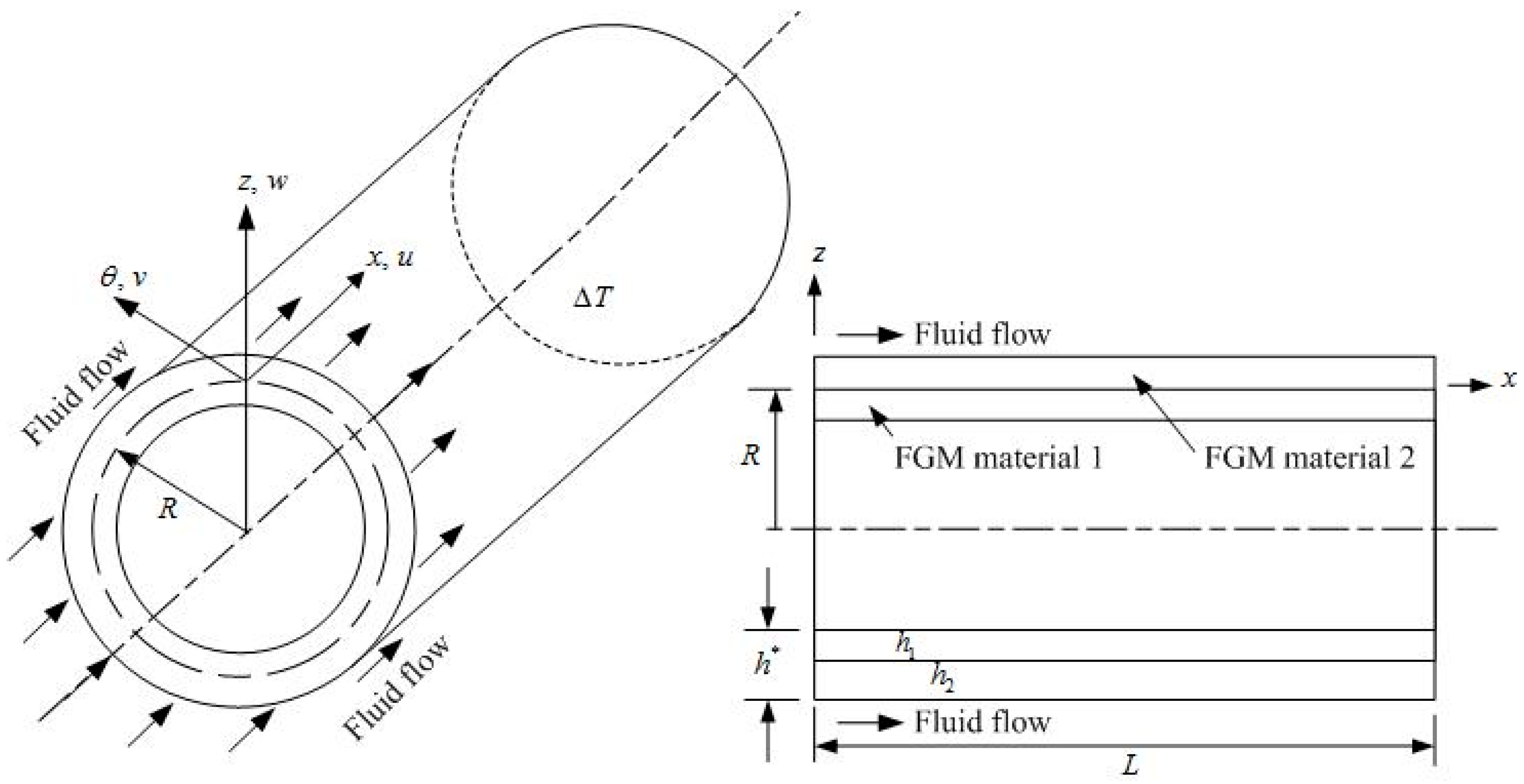
For fluid flow over the outer surface of two-material FGM circular cylindrical shell is shown in
Figure 1 with FGM material 1 thickness
and FGM material 2 thickness
, respectively. The material properties of the power law function of the FGM circular cylindrical shells are considered with a dominated Young’s modulus
of the FGM in the standard variation form of the power law index
, and the others are assumed in the simple average form [
24]. The properties of the individual constituent materials of FGMs are functions of the environmental temperature
.
The time dependency of displacements
,
and
of thick circular cylindrical shells are assumed in the linear FSDT equations as follows [
25]: the formulas are correct only in the case of the symmetric properties with respect to mid-plane. As one knows, density of FGMs is usually not symmetric with respect to the middle-surface; thus, the neutral surface has the role of the middle-surface and, for simplification, the middle-surface is assumed and considered near to the neutral surface of FGMs.
where
and
are tangential displacements,
is transverse displacement of the middle-surface of the shells,
and
are middle-surface shear rotations,
and
are in-surface coordinates of the shell,
is out of surface coordinates of the shell,
is time.
The in-plane stresses constitute the membrane stresses, bending stresses and thermal stresses under temperature difference
for the
kth layer of plane stresses in the thick FGM circular cylindrical shell are provided in the equations as follows [
26,
27]:
The shear stresses are provided as follows:
where
and
are the coefficients of thermal expansion,
is the coefficient of thermal shear,
is the stiffness of the FGM shell.
,
, and
are in-plane strains, not negligible
and
are shear strains.
,
, and
are the curvatures.
is the temperature difference between the FGM shell and curing area can be provided in the equation as follows:
in which
and
are temperature parameters in functions of
,
, and
;
is the total thickness of shells.
The dynamic equations of motion for a circular cylindrical shell are provided by Jafari et al. [
28]. The constitutive relations including thermal loads effect is provided by Lee et al. [
26]. The dynamic equilibrium differential equations of fluid flow over the outer surface of FGM circular cylindrical shells in terms of displacements and shear rotations can be provided and represented as follows:
where
is the middle-surface radius of shells.
are in the expressions of thermal loads
as follows:
in which
is the shear correction coefficient.
is the supersonic aerodynamic pressure load, introduced by Dowell et al. [
29] for the unsteady, inviscid fluid flow over the outer surface of FGM shells with free stream density
, velocity
and Mach number
.
is the density of ply,
and
are the pulsating axial load and moment in function of
. The values of
are usually functions of
,
and
. The simple forms of
and
for FGM circular cylindrical shells can be provided by Sepiani et al. [
30].
The value of shear correction coefficient is usually varied in the FGM shells. The modified shear correction factor
can be provided based on the total strain energy equivalence principle due to transverse shears
and
by Whitney [
27], and
is assumed, the expression of
can be obtained and represented in the following equation:
where the reasonable meaning of
is the effective thickness in shear correction.
and:
in which
is the Poisson’s ratio of the FGM shells,
and:
Shu and Richards presented the GDQ method in 1990 and re-stated the statements as follows: the derivative of a smooth function at a discrete point in a domain can be discrete by using an approximated weighting linear sum of the function values at all of the discrete points in the direction of axes [
16,
31,
32]. The dynamic GDQ discrete equations in matrix notation can be provided in the formulation of dynamic equilibrium differential equations by considering four sides, simply supported, and fluid flow over the outer surface of FGM thick circular cylindrical shells.
3. Numerical Results and Discussion
There are some real applications of considered structures in
Figure 1, e.g., fluid flow over the outer surface of missiles, rockets, and airplanes. To study the GDQ results of varied shear correction coefficient calculations with shell layers in the stacking sequence
, for the four sides simply supported boundary condition, no pulsating axial load and moment (
), and under the external aerodynamic pressure load (
) of supersonic air flow over the outer surface of FGM shells with
lb/in
3, at altitude 50,000 ft, respectively for
(
in/s), for
(
in/s) and for
(
in/s), the coordinates
and
for the grid points of FGM thick circular cylindrical shells are used as follows:
Sinusoidal displacement and temperature of the thermal vibrations are provided as follows:
and with the simple vibration of temperature parameter:
in which
is the natural frequency of the shells,
is the frequency of applied heat flux, and
is the amplitude of temperature.
Two constituent materials of FGMs are provided. FGM material 1 is SUS304 (stainless steel), FGM material 2 is Si
3N
4 (silicon nitride), used for the numerical GDQ computations. The dimensional quantities are used for each example cases, units in mm are used in the deflection amplitude and thickness, and GP
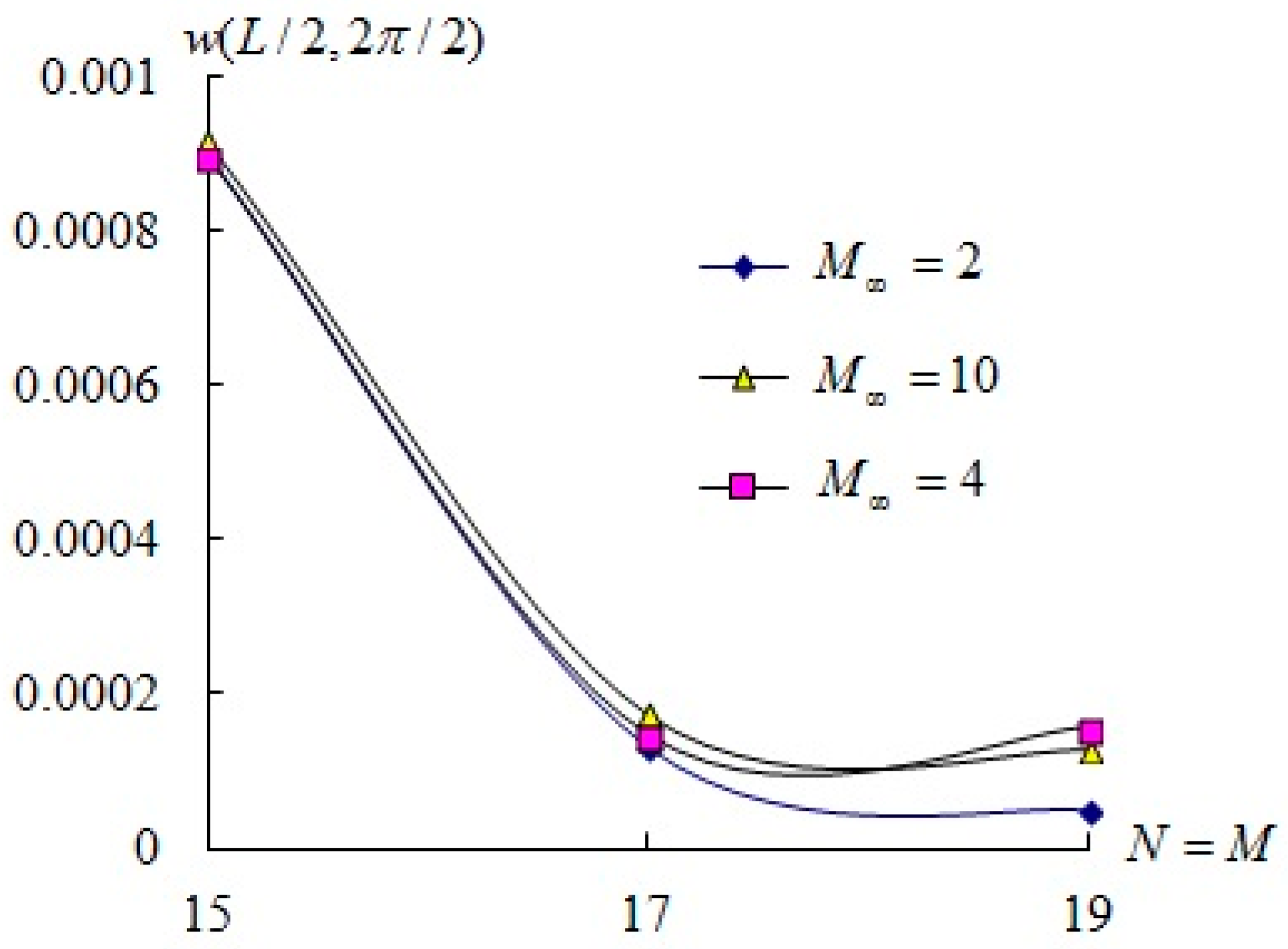
a used for stress. Firstly, the dynamic convergence study of center deflection amplitude
(unit mm) versus
in a supersonic air flow
, 4, and 10, respectively, over the outer surface of circular cylindrical FGM shells are obtained in
Figure 2 by considering the varied effects of shear correction coefficients and with
,
,
mm,
mm,
,
,
,
,
, and
. The
grid points can be treated in the convergence status and used in the following GDQ computations of time responses for deflection and stress in a supersonic air flow over the outer surface of circular cylindrical FGM shells. In the circular cylindrical FGM shell (
), varied values of
are usually functions of
,
and
. For
mm,
, calculated values of
versus
and
are shown in
Table 1, used for the GDQ and shear calculations. For
mm, values of
(from 0.06616 to 0.201838 under
, from 0.0877684 to 0.229368 under
, from 0.059168 to 0.167052 under
) are increasing with
(from 0.1 to 10).
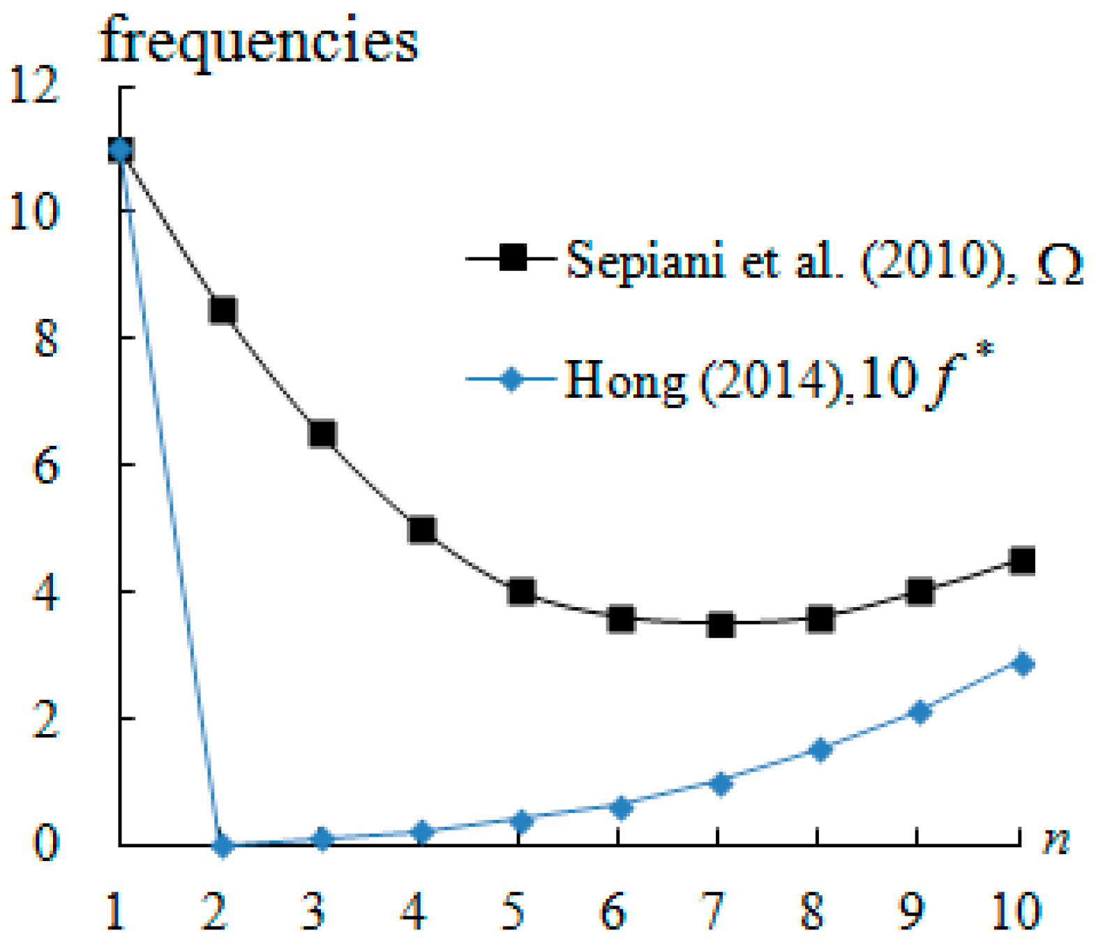
The compared results of frequencies (
and
) versus
are re-plotted in
Figure 3, provided and represented with the varied correction factor value 0.101452 calculated by Hong [
33] and with the constant correction factor value 5/6 = 0.833333 by Sepiani et al. [
30]. The results can be treated as the similar tendency between the two curves of different frequency parameters (
and
) versus
, where
with
, in which
and
are the Young’s modulus,
and
are the Poisson’s ratios of the FGM constituent material 1 and 2, respectively.
, where
,
,
with
,
, and
are effective mass density, effective elastic modulus and effective Poisson’s ratio of FGM, respectively, for a simply supported silicon nitride–nickel FGM cylindrical shell with FSDT under axial extensional loading and no external pressure (
).
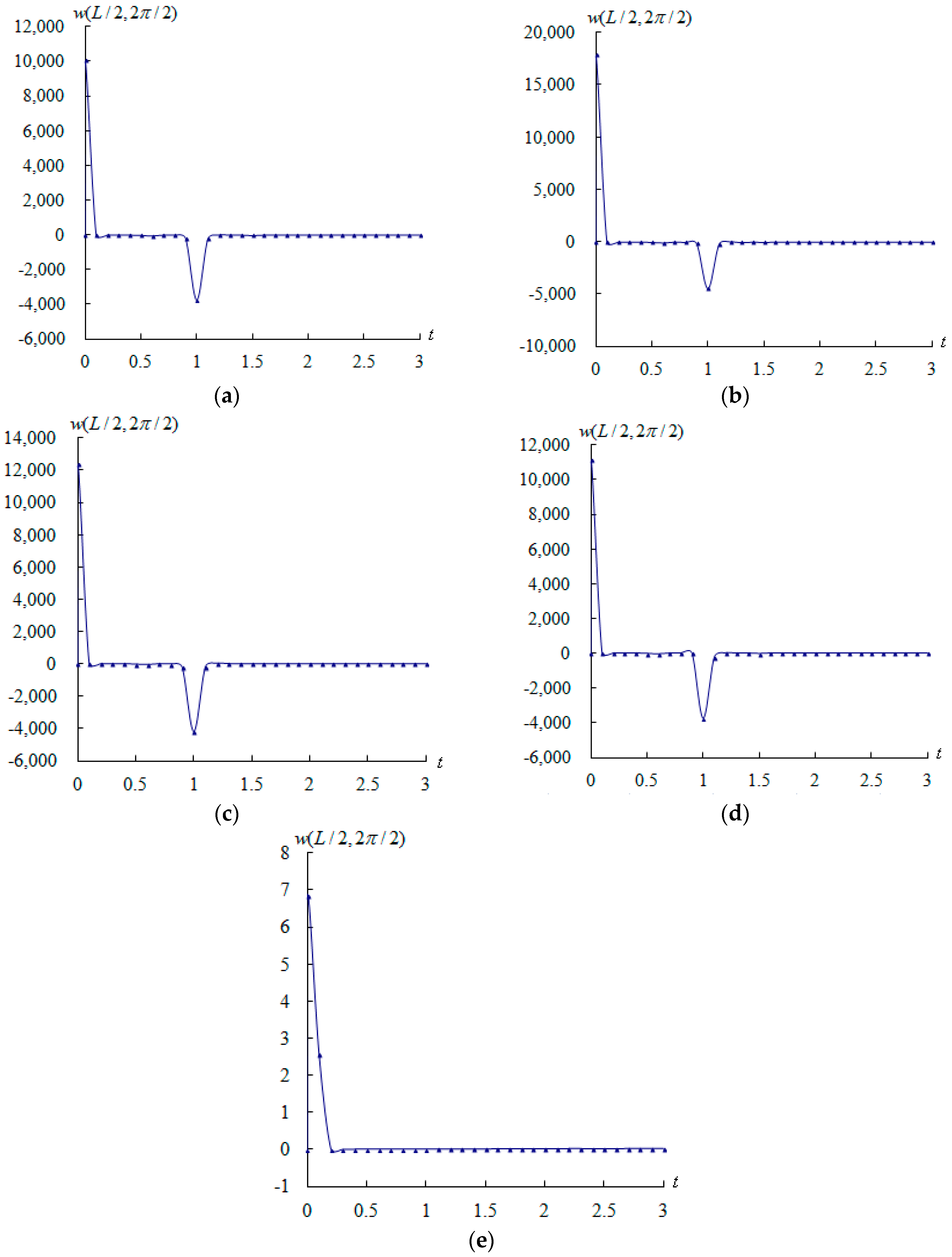
The amplitude of center deflection
(unit mm) for the air flow over the outer surface of FGM circular cylindrical shells is calculated. The response values of amplitude
(unit mm) versus time
(unit s) are shown in
Figure 4 for a supersonic air flow
, 4, and 10, respectively, over the outer surface of the FGM circular cylindrical shells for thick
,
,
,
,
,
,
,
, flutter starting time
s (
/s) , and response time
to 3.0 s with a time step of 0.1 s. The maximum value of amplitude
(unit mm) is, respectively, value 10,053 mm occurs at
s for
, value –3753 mm occurs at
s (
/s) for
, value 17,842 mm occurs at
s for
, value −4457 mm occurs at
s for
, value 12,368 mm occurs at
s for
, value −4189 mm occurs at
s for
. Flutter occurs at
s due to high frequency of applied heat flux value
/s for a supersonic air flow
, 4, and 10. There exists a “jumping” around
s, the nature of such phenomenon might be considered as, and related to, a transonic dip. The abrupt change in time responses of displacement is shock wave vibration occurred at
s in the unsteady air flow shown in
Figure 4a–c, corresponding to the position in a steady air flow
and without air flow (
) are shown in
Figure 4d–e, respectively. The transient value of 11,133 mm in steady air flow occurs at
s is greater than 10,053 mm in unsteady air flow, but the value −3753 mm in steady air flow occurs at
s is in the same value as in unsteady air flow. With the effects of thermal load vibrations and environment temperature only (without air flow), the transient value 6.8 mm occurs at
s, and the value 0.008 mm occurs at
s are found in smaller values. Thus, the “jumping” of amplitudes around
s is due to the effect of air flow pressure and comes from the effect of shockwave vibrations.
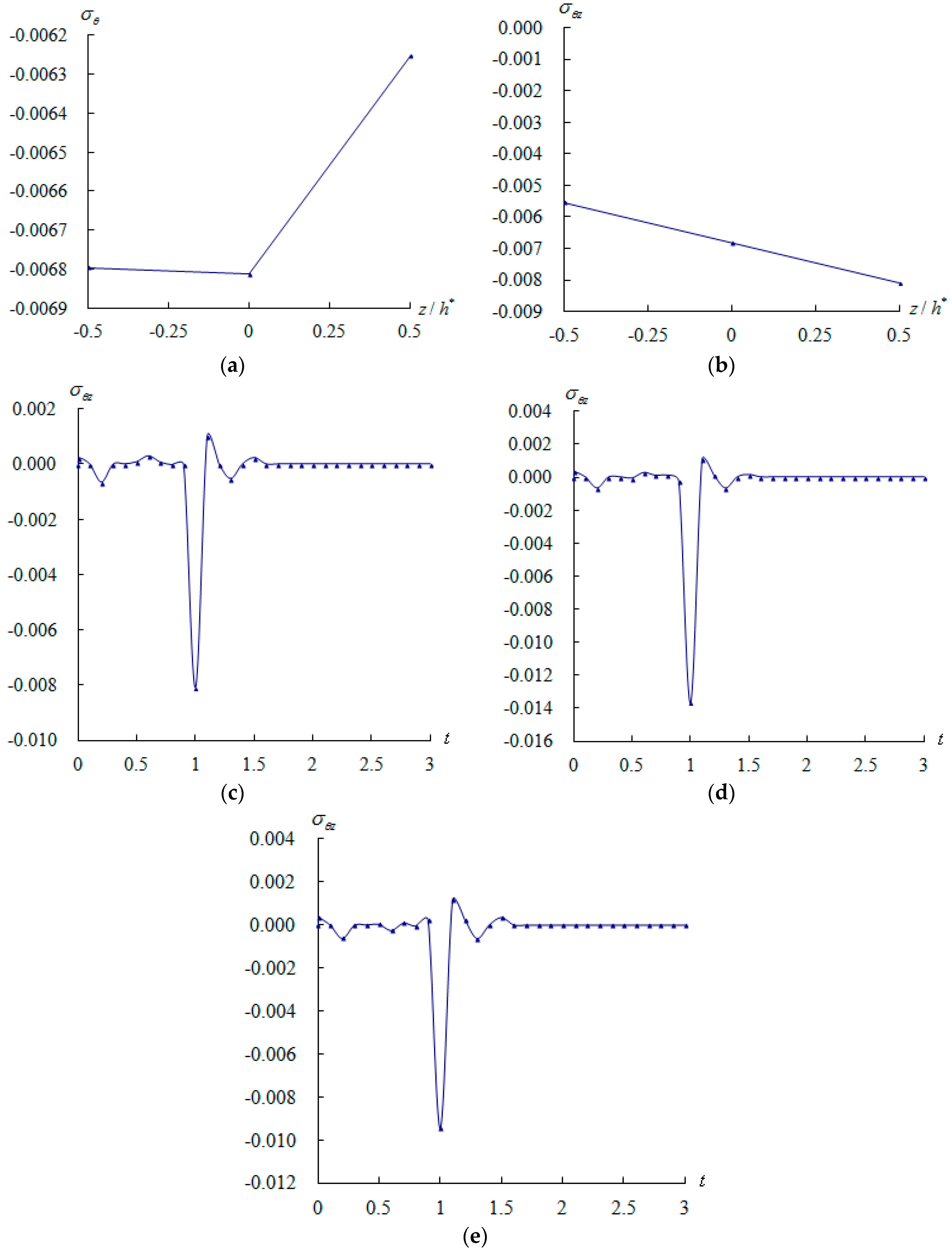
In-plane stress
(unit GP
a) and shear stress
(unit GP
a) are three-dimensional components and usually in functions of
,
, and
. Typically, their values vary through the shell thickness for the air flow over the outer surface of FGM circular cylindrical shells. The in-plane stress
(unit GP
a) versus
for
is shown in
Figure 5a. The shear stress
(unit GP
a) versus
for
at center position (
) of shells is shown in
Figure 5b, respectively at
s,
and
. The absolute value (0.0081 GP
a) of
at
is found in the much greater value than the value (0.00681 GP
a) of
for
; thus, the
can be treated as the dominated stress for the air flow over the outer surface of FGM circular cylindrical shells. The time responses of the dominated shear stresses
(unit GP
a) are shown in
Figure 5c–e at the center position of the outer surface
as the analyses of the deflection cases in
Figure 4 for
,
, air flow
, 4, and 10, respectively. The maximum absolute value of
is 0.0137 GP
a occurs at
s for
.
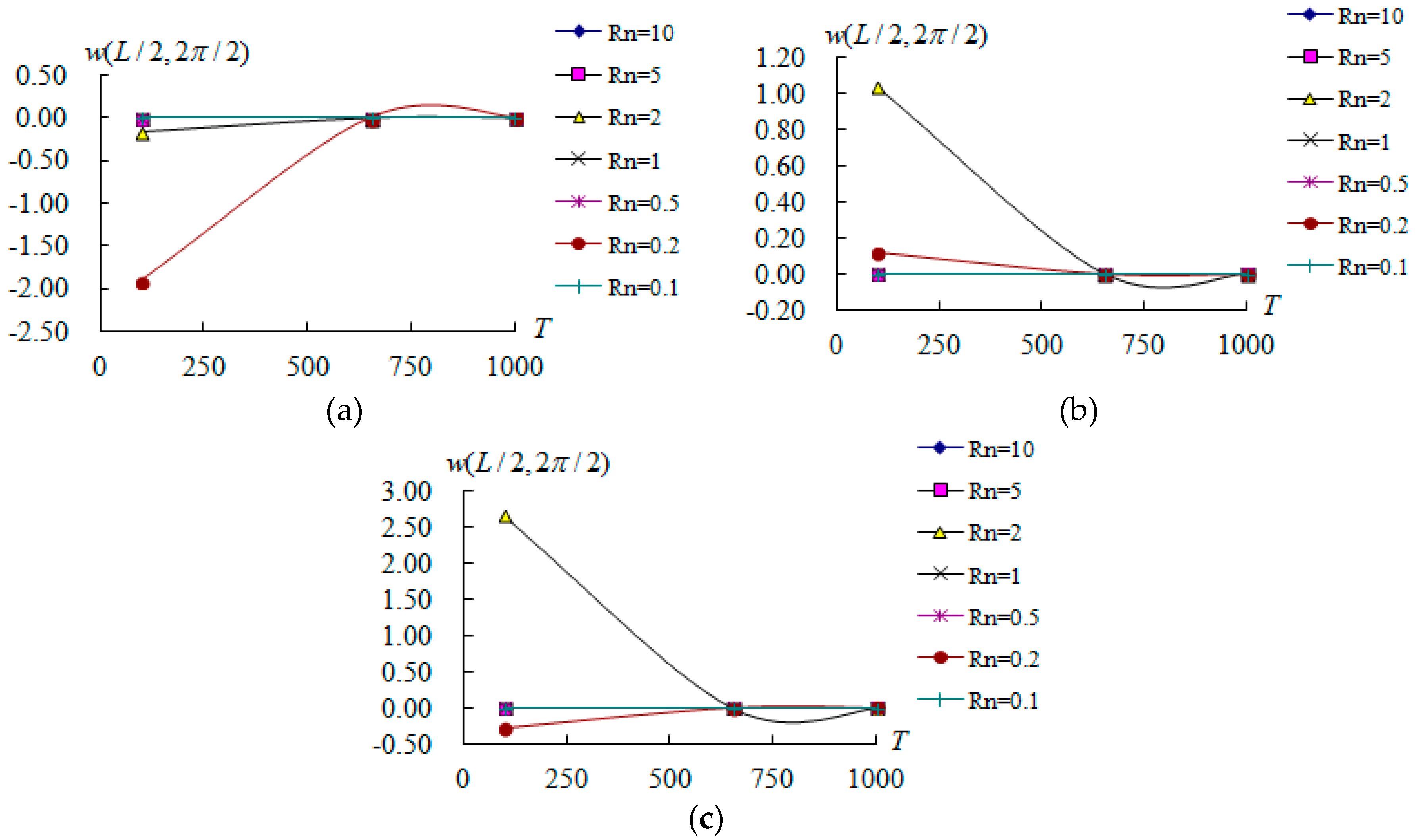
The amplitudes
(unit mm) versus
(unit
) and
values (from 0.1 to 10) are shown in
Figure 6 for air flow
, 4, and 10, respectively, over the outer surface of FGM circular cylindrical shells calculated and varied values of
, for
,
,
,
,
, at
s (
/s). The maximum value of amplitude
is 1.91346 mm occurs at
and
for
is shown in
Figure 6a. The amplitude
values are all decreasing versus
for values
and 2, and they can withstand higher environmental temperature (
). The amplitude
value is decreasing (from −1.91346 mm to 0.0000066 mm) versus
for the dominated value
, and it can withstand higher environmental temperature (
). The maximum value of amplitude
is 1.03639 mm, occurring at
and
for
, is shown in
Figure 6b. The amplitude
values are all decreasing versus
for values
and 2, they can withstand higher environmental temperature (
). The amplitude
value is decreasing (from 1.03639 mm to 0.0000273 mm) versus
for the dominated value
, and it can withstand higher environmental temperature (
) . The maximum value of amplitude
is 2.65509 mm, occurring at
and
for
, is shown in
Figure 6c. The amplitude
values are all decreasing versus
for values
and 2, and they can withstand higher environmental temperature (
). The amplitude
value is decreasing (from 2.65509 to 0.0000271 mm) versus
for the dominated value
, and it can withstand for higher environmental temperature (
).
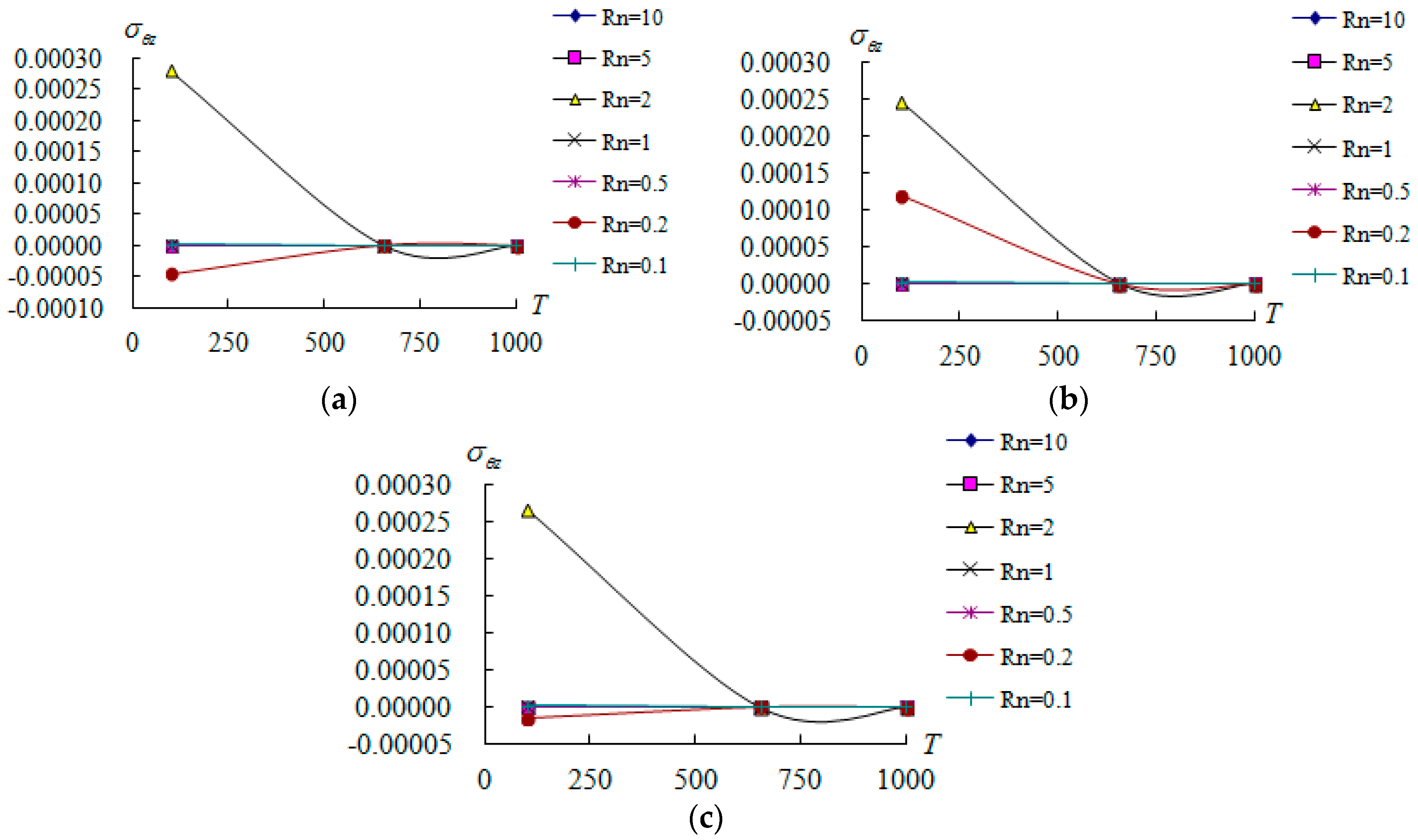
The shear stress
(unit GP
a) at center position of outer surface
versus
(unit
) and
are shown in
Figure 7 for air flow
, 4, and 10, respectively, over the outer surface of the FGM circular cylindrical shells as the analyses of deflection case in
Figure 6. The maximum value of
is 0.000281 GP
a, occurring at
and
for
, is shown in
Figure 7a. The absolute values of
are all decreasing versus
for
and 2, they can withstand higher environmental temperature (
). The maximum value of
is 0.000247 GP
a, occurring at
and
for
is shown in
Figure 7b. The absolute values of
are all decreasing versus
for
and 2, they can withstand for higher temperature (
) of environment. The maximum value of
is 0.000267 GP
a occurs at
and
for
is shown in
Figure 7c. The absolute values of
are decreasing versus
for
, and they can withstand higher environmental temperature (
).


