
Development of Hollow Cathodes for Space Electric Propulsion at Sitael

1
Space Propulsion Division, Sitael, 56121 Pisa, Italy
2
Department of Civil and Industrial Engineering, University of Pisa, 56126 Pisa, Italy
*
Author to whom correspondence should be addressed.
Aerospace 2017, 4(2), 26; https://doi.org/10.3390/aerospace4020026
Submission received: 9 March 2017
/
Revised: 26 April 2017
/
Accepted: 3 May 2017
/
Published: 6 May 2017
(This article belongs to the Special Issue State-of-the-Art Aerospace Sciences and Technologies in Europe)
Abstract
:Hollow cathodes are electron sources used for the gas ionization and the beam neutralization in both ion and Hall effect thrusters (HETs). A reduction of power and propellant consumption from the cathode is particularly needed in small satellite applications, where power and mass budgets are inherently limited. Concurrently, the interest in high-power HETs is increasingly fostered for a number of space applications, including final positioning and station-keeping of Geostationary Earth Orbit (GEO) satellites, spacecraft transfers from Low Earth Orbit (LEO) to GEO, and deep-space exploration missions. As such, several hollow cathodes have been developed and tested at Sitael, each conceived for a specific power class of thrusters. A numerical model was used during the cathode design to define the geometry, in accordance with the thruster unit specifications in terms of discharge current, mass flow rate, and lifetime. Lanthanum hexaboride (LaB6) hollow cathodes were successfully developed for HETs with discharge power ranging from 100 W to 20 kW. Experimental campaigns were carried out in both stand-alone and coupled configurations, to verify the operation of the cathodes and validate the numerical model. The comparison between experimental and theoretical results are presented, offering a sound framework to drive the design of future hollow cathodes.
1. Introduction
Hollow cathodes based on thermionic electron emission are used in space electric propulsion to supply electrons for propellant ionization and beam neutralization of both ion engines and Hall effect thrusters (HETs). The cathode mass flow rate in xenon fed HETs tends to be 7%–10% of the anode mass flow rate [1], whereas the cathode power consumption can reach up to 20% of the available power [2]. As such, a performance improvement of the cathode can have a significant impact on the overall performance of the thruster unit in small satellite applications, where the power and mass budgets are limited. Hollow cathodes are also being developed for high-power HETs, to perform in-space transportation of large masses, orbit transfer and exploration missions. The benefits provided by electric propulsion are tied to a lower propellant mass with respect to chemical propulsion, allowing for a higher payload mass, a lower total mass, therefore less expensive launch vehicles [3]. In general, the spacecraft application of the hollow-cathode technology demands a power consumption minimization, while maintaining a lifetime in the order of 104 h. Since the cathode performance is strongly tied to its geometry and size, numerical tools are required to select the geometries and operating conditions for a given mission profile. Several numerical models have been developed to determine the plasma properties in hollow cathodes [4,5,6]. However, in these models, experimental data are used as input or assumptions are made to set the plasma density, the electron temperature, or the coupling voltage to the keeper [5]. A reduced-order model was thus proposed to overcome these limitations through the development of a self-consistent code, encompassing all the relevant components of an orificed hollow-cathode assembly [7]. The theoretical study paved the way to the development of several hollow cathodes, for Hall effect thrusters belonging to different power classes [8].
2. Cathode Design
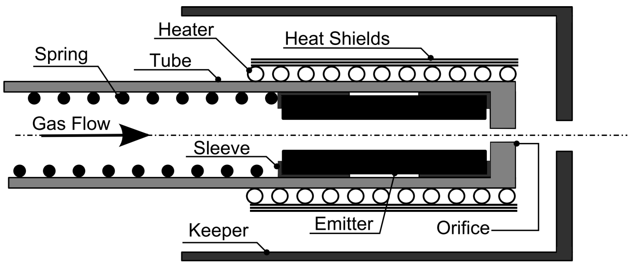
The cathode design features the same basic components as conventional thermionic hollow cathodes (Figure 1). The active electron emitter is a lanthanum hexaboride (LaB6) hollow cylinder, located inside a refractory metal tube and pushed against an orifice by means of a tungsten spring. The direct contact of the LaB6 insert with the refractory metal tube is prevented by means of graphite sleeves. An electrode denoted as keeper encapsulates the internal elements, and is made from refractory metals, titanium alloy, or graphite. The cathode can be provided with a heater, which is wrapped around the tube to raise the emitter temperature to thermionic emission values. The heater is made of a tungsten/rhenium filament electrically isolated by the tube by means of a boron nitride insulator, and is immersed in a ceramic potting. Tantalum heat shields are wrapped around the heater to improve the thermal behavior of the cathode, through a reduction of the power radiated towards the keeper. The function of the heater is to reduce the emitter thermal stress at the cathode start-up and to ease the thermionic electron emission from the emitter prior to each ignition, due to an increased surface temperature. The cathode is assembled by means of screws, which allow for rapid modifications in the cathode configuration, i.e., the inclusion of a heater or the replacement of the orifice plate. The geometrical features of the cathodes described in the following sections are not specified due to property rights.
Concerning the emitter material, LaB6 has been selected for the high robustness in handling and processing, capability to deliver high current densities in the order of 105 A/m2 [4], and long life, with respect to the traditional dispenser cathodes. Dispenser emitters feature a tungsten matrix impregnated with barium-based mixtures and rely on chemical reactions to form a low-work-function surface layer [4]. They are thus susceptible to poisoning that can increase the emitter work function or even hinder the cathode operation. A LaB6 emitter does not require lengthy activation procedures and has a low sensitivity to contaminants and air exposure, increasing the cathode reliability. The main disadvantage of LaB6 with respect to dispenser emitters is the higher work function, which is between 2.4 and 2.7 eV for polycrystalline LaB6 cathodes [9,10], compared to about 2.1 eV for dispenser cathodes [4]. This property directly translates into operating temperatures of over 1600 °C for LaB6 emitters compared to over 1000 °C for dispenser emitters, to deliver current density in the order of 105 A/m2. Given the high temperatures required, developing a heater to reach ignition temperatures and efficiently reducing heat losses during operation is a significantly challenging task for LaB6 cathodes.
The cathode geometry was selected on the basis of a theoretical model previously developed at Sitael, which describes the operation of a hollow cathode [7]. A global (volume-averaged) model appeared to be the most practical compromise between including details and keeping the model flexible and time-saving. The model is self-consistent: once defined the cathode geometry and the operating conditions in terms of discharge current and mass flow rate, the plasma parameters, surface temperatures, and total discharge power are estimated by solving a system of particle and energy balance equations [7]. The dependence of the results on the geometry can thus be assessed to target the definition of the main dimensions of the cathode, i.e., emitter inner and outer diameters, emitter length, orifice diameter, and orifice length. The work function of LaB6 considered in the computation is 2.66 eV, along with a Richardson constant of 29 A·cm−2·K−1, in accordance with the values reported by Lafferty [9]. The cathode lifetime is estimated on the basis of an evaporation model at the computed emitter surface temperature, where the lifetime is described as the time to halve the emitter initial mass. Other life-limiting mechanisms such as keeper or orifice plate erosion, or heater life, are not considered [11].
3. Low-Current Hollow Cathodes
Low-power Hall effect thrusters are a sub-class of HETs with an operating power lower than 500 W, which can be installed onboard small satellites to perform a wide variety of missions, ranging from drag compensation in LEO to final orbit insertion, and spacecraft end-of-life disposal [12]. In this context, two hollow cathodes were designed, to be coupled with the Sitael 100 W and 400 W Hall thrusters. The cathodes are named as HC1 and HC3, where the number refers to the current level each cathode was designed for.
3.1. HC1
A hollow cathode for 100 W-class Hall thrusters was designed, to provide a discharge current in the 0.3–1 A range [13]. The cathode operates in steady-state conditions at mass flow rates between 0.08 and 0.5 mg/s of xenon. The cathode can include a heater, designed to deliver up to 30 W to ease the cathode ignition. The expected cathode lifetime, estimated on the basis of the theoretical model, is higher than 104 h.
3.1.1. Experimental Setup
HC1 was experimentally characterized during a dedicated stand-alone test campaign, after which the cathode was coupled with the Sitael HT100D 100 W-class Hall thruster [14]. A current-limited Huettinger Electronic, Inc., PFG5000 (1000 V, 6 A, Farmington, CT, USA) power supply controlled the cathode-to-keeper voltage during discharge initiation and the current during operation. During the stand-alone experiments, an external anode plate was located about 15 mm downstream of the cathode. The cathode-to-anode current was controlled using a Ametek Programmable Power, Inc., Sorensen DLM 300-3.5E (300 V, 3.5 A, San Diego, CA, USA) power supply. The heater current was controlled using a Sorensen DCS 80-13E (80 V, 13 A) power supply. All the power supplies were connected to a common negative reference and the setup was electrically floating with respect to ground. The gas feeding system of the cathode was equipped with a dedicated mass flow controller (Bronkhorst High-Tech B.V., F-201C-FAC-22-V, Ruurlo, The Netherlands). Grade N48 xenon was used during the test campaigns. The temperature at the mounting interface of the cathode was monitored by means of a K-type thermocouple. A mass flow controller (Bronkhorst F-201C-FAC-88-V) was added in the setup to feed the anode, during the coupling tests with the HT100D thruster.
3.1.2. Cathode Performance
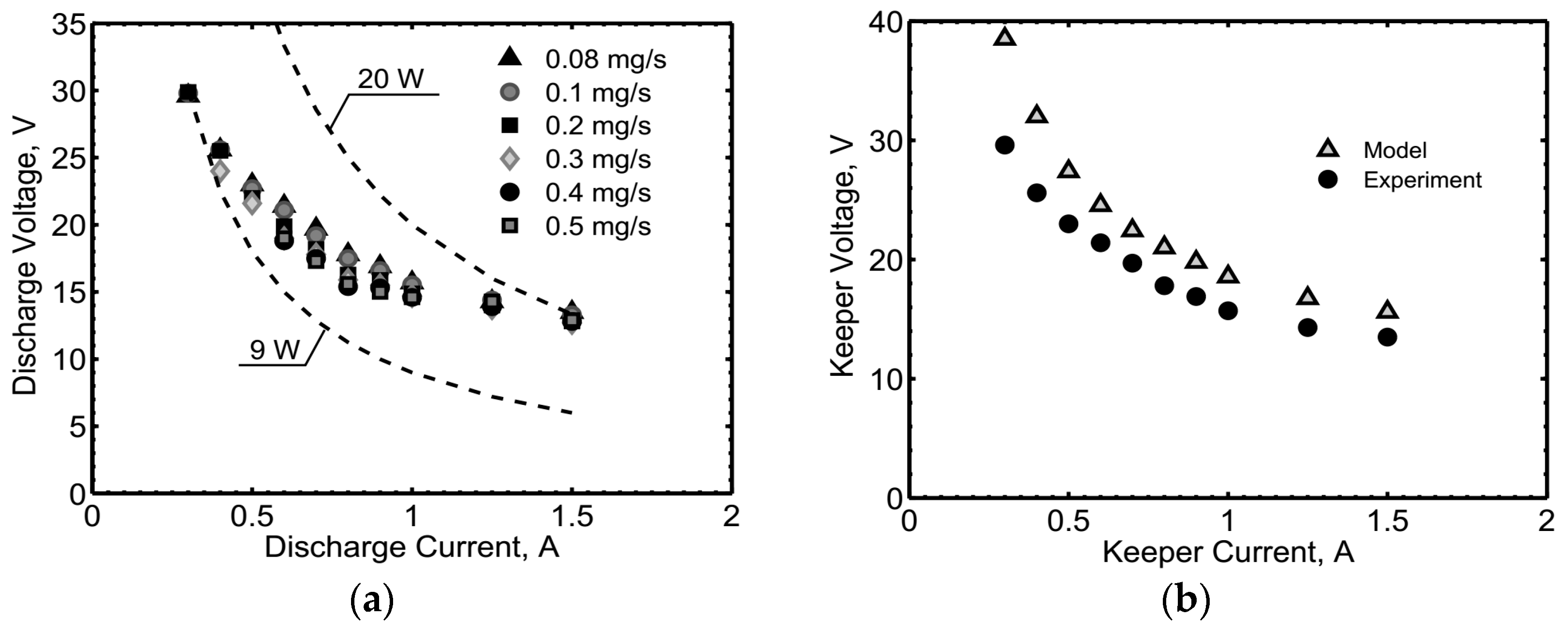
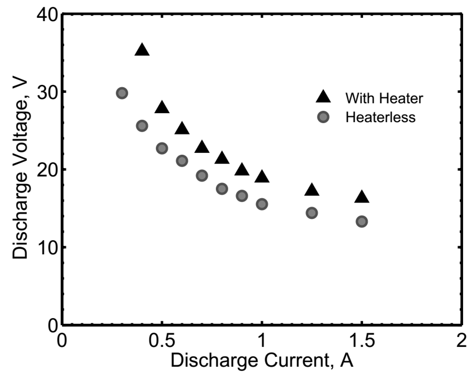
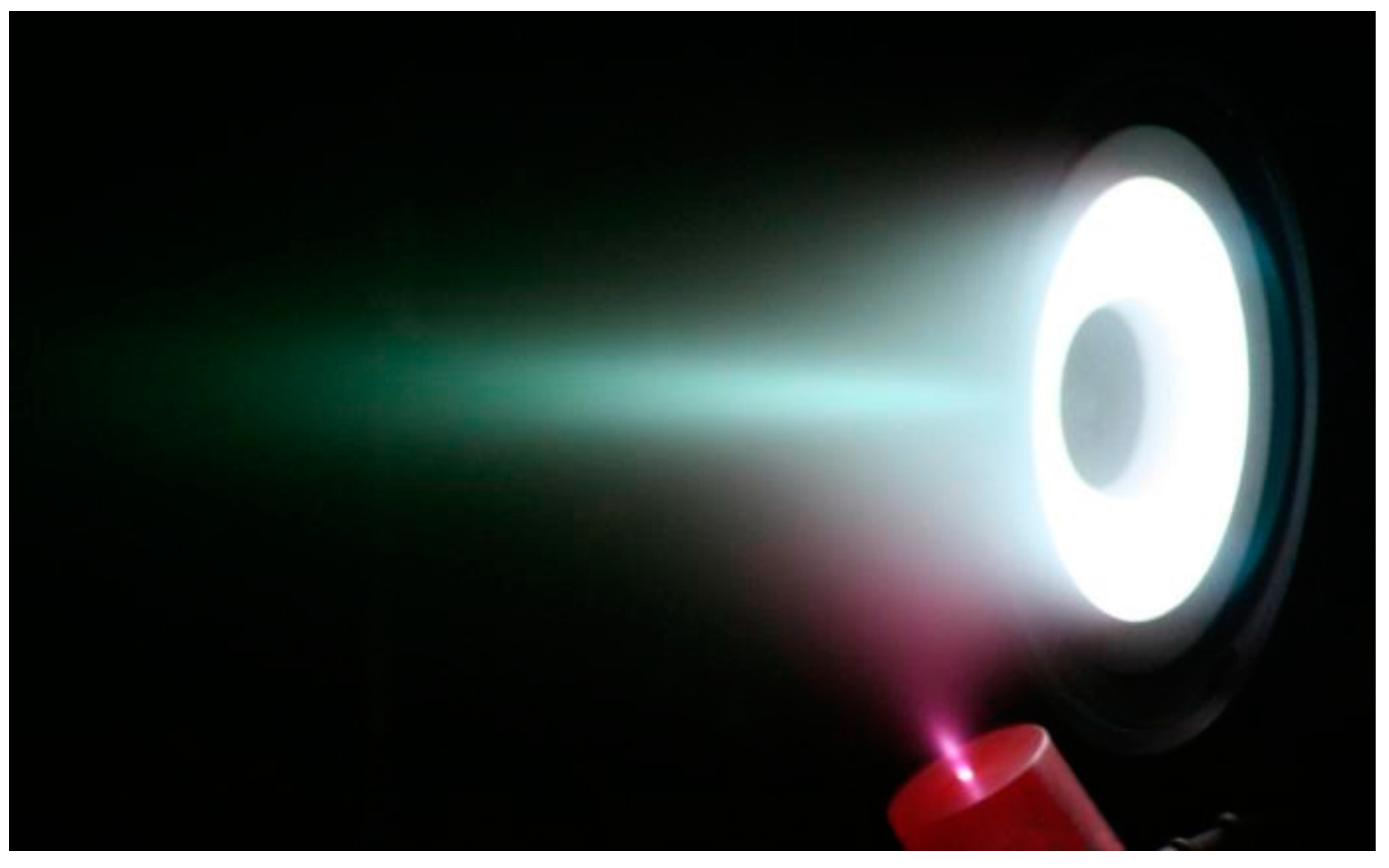
The cathode internal pressure was measured at room conditions, flowing a xenon mass flow rate between 0.1 and 1.5 mg/s. The cathode pressure model, based on a Poiseuille flow in the orifice region, was used as a stand-alone code to decouple the dependence of the pressure on the plasma. The collected data are reported in Figure 2a, together with the theoretical predictions, which show a fairly good agreement with the experimental curve. The pressure comparison for the cathode operated in diode mode with 1 A keeper current is shown in Figure 2b. The parameter Th/Tw represents the ratio of the heavy particles temperature, Th, to the cathode wall temperature, Tw. As expected [15], a value of Th/Tw comprised between 1 and 4 gives a good estimate of the cathode internal pressure. In the heaterless configuration, the cathode was ignited by flowing 1 mg/s Xe, applying 700 V to the keeper, and regulating the keeper power supply to 1 A. On the other hand, a heater power of about 23 W allowed for starting the cathode with keeper voltages lower than 400 V with 0.4 mg/s Xe. The electrical characteristics collected in diode mode with the keeper alone (without the anode operating) in steady state conditions are shown in Figure 3a, at different mass flow rates between 0.08 and 0.5 mg/s. The presented results refer to the heaterless configuration. The discharge voltage was found to decrease from about 30 to 15 V, when increasing the current from 0.3 to 1.5 A. The total discharge power of HC1 with the keeper alone is in the range from 9 to 20 W, depending on the operating conditions. The discharge voltage showed a negligible dependence on the mass flow rate, as expected during the cathode operation in spot mode [4], being identified by low voltage oscillations and broad optimum gas flow at a given current. The results of the model, in terms of electrical characteristics, are in good agreement with the experimental data (20% of discrepancy for the worst prediction), as shown in Figure 3b at a fixed mass flow rate. The electrical characteristic at 0.1 mg/s Xe of the cathode with heater in diode mode with the keeper alone (without the anode operating) is compared with the heaterless case in Figure 4. As expected, the additional mass of the heater, although thermally shielded by means of a tantalum foil, implied an additional conduction of the heat away from the emitter and an increased radiation area, causing a less-efficient thermal behavior of the cathode during the steady-state operation due to higher power losses, ultimately leading to an increased voltage drop at the emitter sheath with respect to the heaterless case. The increase in the discharge voltage ranges from about 9.5 to 2 V, for a discharge current increasing from 0.4 to 1.5 A, as shown in Figure 4. Figure 5a shows HC1 operating with keeper and anode in the stand-alone configuration, where the current was split between the two electrodes not to excessively increase the keeper temperature. HC1 is also shown in Figure 5b, during steady-state operation with HT100D and floating keeper.
3.2. HC3
A hollow cathode was conceived for the Sitael 400 W-class Hall thruster HT400 and designed to provide a current up to 3 A, hence the name HC3. The cathode operates at nominal mass flow rates between 0.08 and 0.5 mg/s of xenon. The cathode can be provided with a heater, to supply up to 50 W of power during the ignition transient. The expected cathode lifetime is higher than 104 h.
3.2.1. Experimental Setup
HC3 was characterized with the aid of an auxiliary anode plate. After the stand-alone campaign, the cathode was coupled with the HT100D thruster, whereas the coupling test with HT400 is still being planned according to the activities related to the thruster development. The same experimental equipment described in Section 3.1.1 was adopted for both the stand-alone and the coupling test campaigns.
3.2.2. Cathode Performance
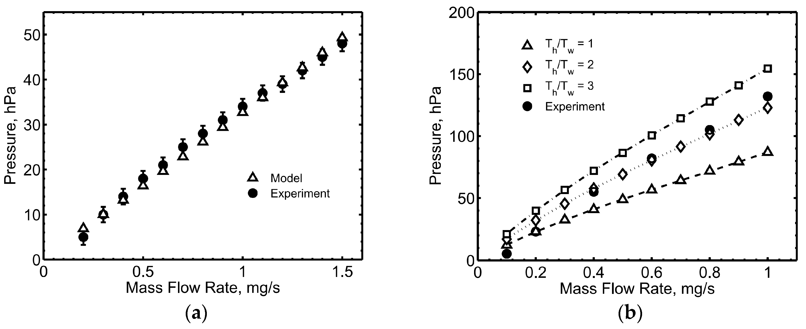
Measurements of the cathode pressure were performed and compared with the theoretical results from the numerical model. Figure 6a reports the cathode pressure measured at room temperature (no discharge), at xenon mass flow rates from 0.2 to 1.5 mg/s. The presented data are in excellent agreement with the values predicted by the pressure model. Figure 6b shows the cathode pressure during operation in diode mode with the keeper electrode alone, with a current limited to 3 A. The cathode pressure increased from about 5 to 130 hPa (namely, from about 3.8 to 97.5 torr), when the mass flow rate was increased from 0.1 to 1 mg/s. The theoretical pressure at the highest mass flow rate (i.e., 1 mg/s) is in reasonably good agreement with the measured one for a ratio of the plasma heavy particles temperature and the wall temperature between 2 and 3, which is in agreement with the experimental findings by Williams [15]. On the contrary, the model slightly over-predicted the pressure value recorded at the lowest mass flow rate (i.e., 0.1 mg/s), even when considering the heavy particles in a thermal equilibrium condition with the cathode walls. A fixed ratio of the plasma heavy particles temperature and the wall temperature does not provide good agreement of the computed pressure with the experimental values as a function of the mass flow rate. This occurrence is likely tied to the influence of the plasma parameters on the ion energy, which affects the charge exchange mechanism between ions and neutrals, and in turn the neutral gas temperature.
In its heaterless configuration, the cathode was ignited by combining 950 V of keeper voltage and an anode voltage comprised between 250 and 500 V, with a mass flow rate between 1 and 2 mg/s. The keeper current was limited to 1.5 A. In the case where a heater was included, a heater power of about 50 W was delivered to the cathode, before applying the keeper voltage.
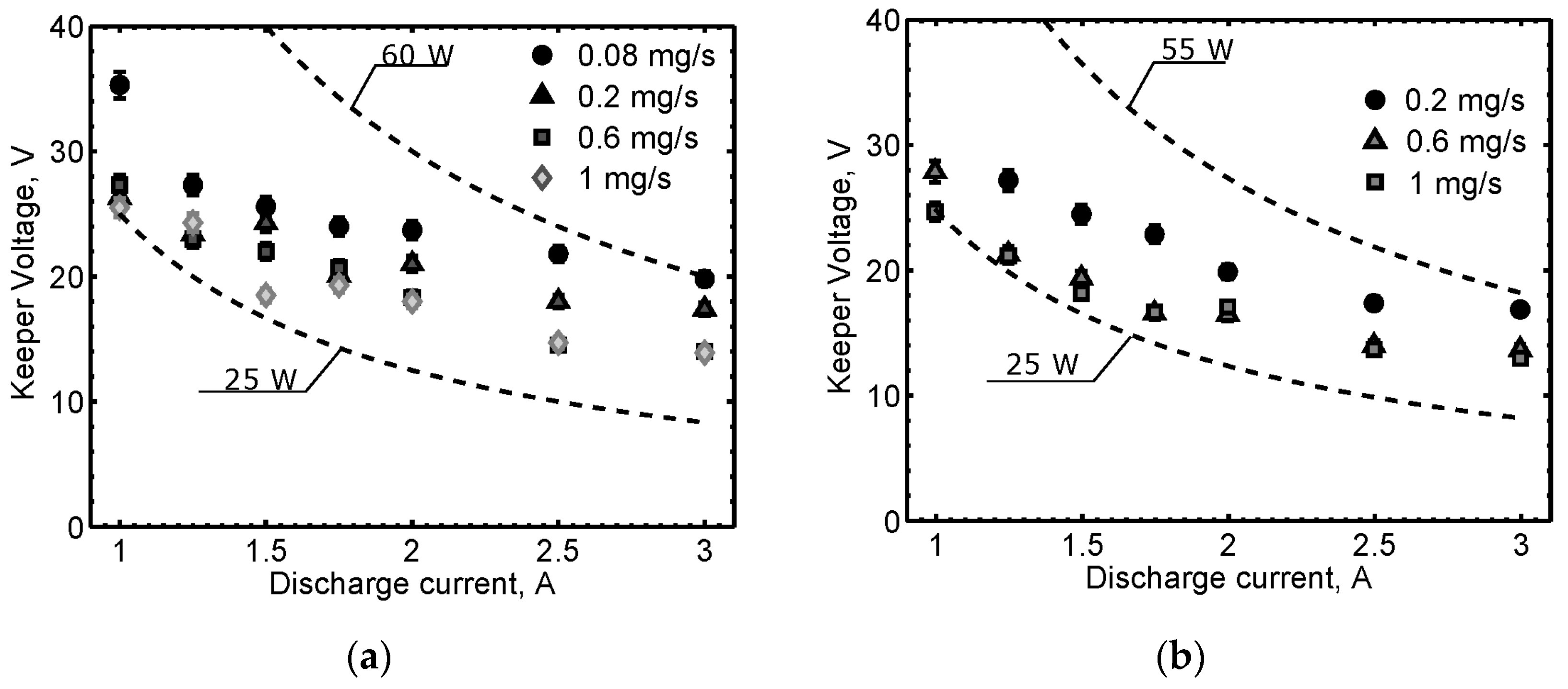
The heater significantly eased the cathode ignition and lowered the required keeper voltage to values on the order of 300 V. The mass flow rate for the cathode ignition was set equal to 0.4 mg/s. Nevertheless, the ignition parameters were deteriorated after about 100 ignitions, where the required mass flow rate and the keeper voltage were increased to 0.8 mg/s and 700 V, respectively. Given that the orifice plate could be easily replaced in the assembly, the cathode was tested with two different length-to-diameter aspect ratios (ARs), equal to 1.2 and 0.9, to assess the effect of this parameter on the cathode performance. The electrical characteristics in diode mode with the keeper alone (without the anode operating) are shown in Figure 7. No substantial voltage variations between the two configurations can be observed in the operating range investigated. The cathode discharge power was found to be comprised between about 25 and 60 W, with a minimum at 1 mg/s and 1 A, independently of the aspect ratio. The discharge voltage decreased when increasing the discharge current, settling in a range from 14 to 35 V in the various operating conditions. The comparisons of the electrical characteristics with the model results are shown in Figure 8, at two different mass flow rates for the AR 1.2 cathode in diode mode with the keeper alone. Consistent with data available in the literature, a general trend of a lower voltage with higher mass flow rates was observed during the experiments, and is correctly captured by the theoretical model. Figure 9 shows HC3 during a coupling test with the thruster HT100D.
4. High-Current Hollow Cathodes
The interest in high-power Hall effect thrusters is increasingly fostered for a number of different space applications, including final positioning and station-keeping of GEO satellites, spacecraft transfers from Geostationary Transfer Orbit (GTO) to GEO (or from LEO to other high-altitude orbits), and deep-space missions [12]. Hall effect thrusters provide an optimal trade-off between specific impulse and thrust, along with a higher thrust-to-power ratio with respect to other electric propulsion technologies [4]. As such, the development of high-power Hall thrusters represents an important step to improve the propulsion systems capabilities for space exploration, allowing for acceptable mission durations. In this context, two hollow cathodes were designed and tested at Sitael, conceived for 5 to 20 kW Hall effect thrusters.
4.1. HC20
A lanthanum hexaboride (LaB6) hollow cathode for 5 kW Hall thrusters, named HC20, has been developed and tested. The cathode was designed to provide discharge currents in the 8–20 A range with a lifetime in excess of 104 h, with mass flow rates between 1 and 4 mg/s. A heaterless configuration was selected, promoting the removal of the single point of failure represented by the heater. The major drawback of this choice lies in the higher voltages required to ignite the cathode, and to possible thermal shocks damaging the LaB6 emitter. The cathode was characterized with both xenon and krypton propellants. The interest in krypton is tied to the reduction of on-ground development and qualification costs, and also to relax the dependence on the volatile natural-resource market. A successful operation of the cathode was observed with both propellants in the investigated range of operating conditions.
4.1.1. Experimental Setup
HC20 was tested with the aid of an anode plate located 70 mm downstream of the cathode. The keeper power supply was a Huttinger PFG5000, whereas the cathode-to-anode current was controlled using a Sorensen DLM 150-20E (150 V, 20 A) power supply. Both power supplies were connected to a common negative reference and the setup was electrically floating with respect to ground. A Bronkhorst F-201C-FAC-22-V mass flow controller was used to feed the cathode. High purity (grade N48) xenon and krypton were used during the test campaigns. K-type thermocouples were installed on the mounting flange constituting the mechanical interface, on the outer keeper flange and on the backside of the anode. Two additional B-type thermocouples suited for measurements up to 1800 °C were installed on the external surface of the cathode main tube at 12 and 41 mm upstream of the tip. HC20 was then coupled with the Sitael HT5k Hall thruster [16]. During the coupling tests with the thruster, the cathode-to-keeper voltage was controlled by a Magna-Power Electronics, Inc., XR1000-6.0 (1000 V, 6 A, Flemington, NJ, USA) power supply, whereas the cathode-to-anode current was controlled by a Magna-Power TSD400-36 (400 V, 36 A) power supply. The gas feeding system consisted of two independent lines as described in Section 3.1.1.
4.1.2. Cathode Performance
The cathode was operated with xenon before and after a 300-h endurance test at 1 mg/s and 16 A anode current (floating keeper), in a stand-alone configuration. In addition, krypton propellant was used after the endurance test for a comparison with the xenon-fed cathode performance. The ignition procedure with xenon propellant consisted in applying 800 V to the keeper and 130 V to the anode. The keeper current was regulated to 2 A and the anode current was set to 16 A. A mass flow rate of 5 mg/s was then flowed through the cathode, which was run at a total current of 18 A for about 30 min before starting each characterization test. Immediately after the discharge initiation, the mass flow rate was smoothly reduced to 1 mg/s in a couple of minutes. A similar procedure was adopted with krypton propellant, with the following ignition parameters: 800 V keeper voltage, 2 mg/s Kr mass flow rate, 2 A keeper current, 130 V anode voltage, and 10 A anode current. The mass flow rate was reduced to 0.8 mg/s as soon as the discharge was stable.
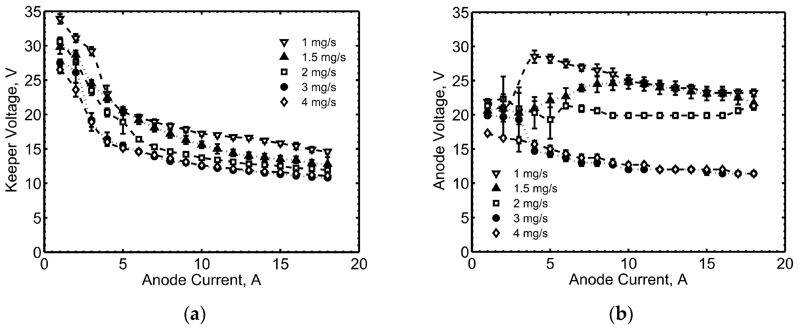
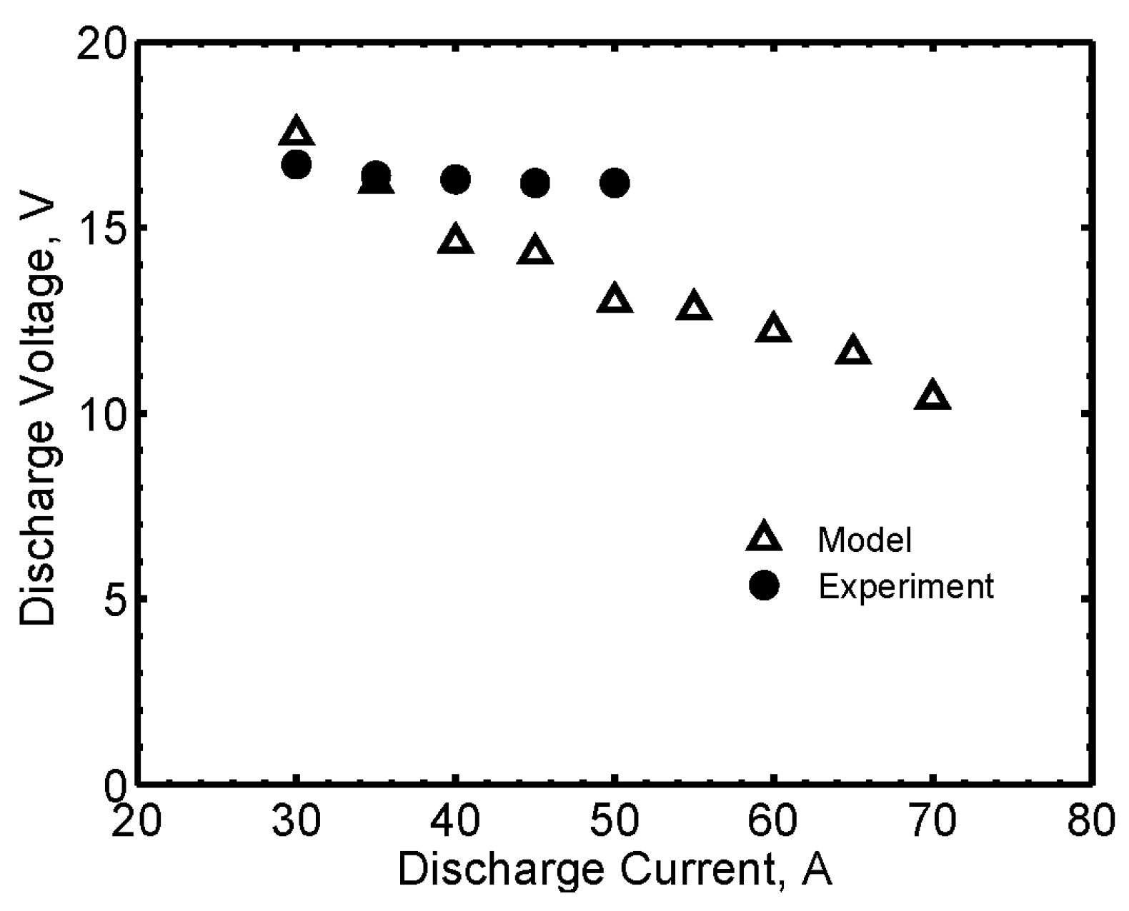
As regards the electrical characteristics, the comparison of pre-endurance and post-endurance keeper voltage is shown in Figure 10a, at 2 A keeper current and 1 mg/s Xe, with the corresponding anode voltage reported in Figure 10b. The error bars shown in the figures reflect the standard deviation found in the collected data, including an error of ±2% associated with the DC voltage measurements (some markers in the graphs hide the error bars). The comparison of the keeper voltage shows a difference of 1–4 V between the pre-endurance and the post-endurance values. At anode currents below 2 A, the anode voltage increased and the cathode tended to cool off, likely due to an insufficient ion-bombardment self-heating. The oscillations of the anode voltage as a function of the anode current likely correspond to mode changes [17,18]. HC20 was also tested with krypton, with similar trends in the electrical characteristics with respect to xenon, as shown in Figure 11. Representative comparisons are reported in Figure 12, where the results of the theoretical model are compared with the experimental data, showing a good agreement of the electrical characteristics, both in the voltage values and in the general trends with the current. The pre-endurance keeper voltage is compared with the corresponding numerical results in Figure 12a, as a function of the anode current, at 2 A keeper current and 1 mg/s Xe. The maximum discrepancy is about 3 V, and the model proved to predict the keeper voltage values with a difference lower than 20%. A very good agreement between theoretical and experimental results was found for the cathode operating with krypton propellant, as shown in the comparison reported in Figure 12b.
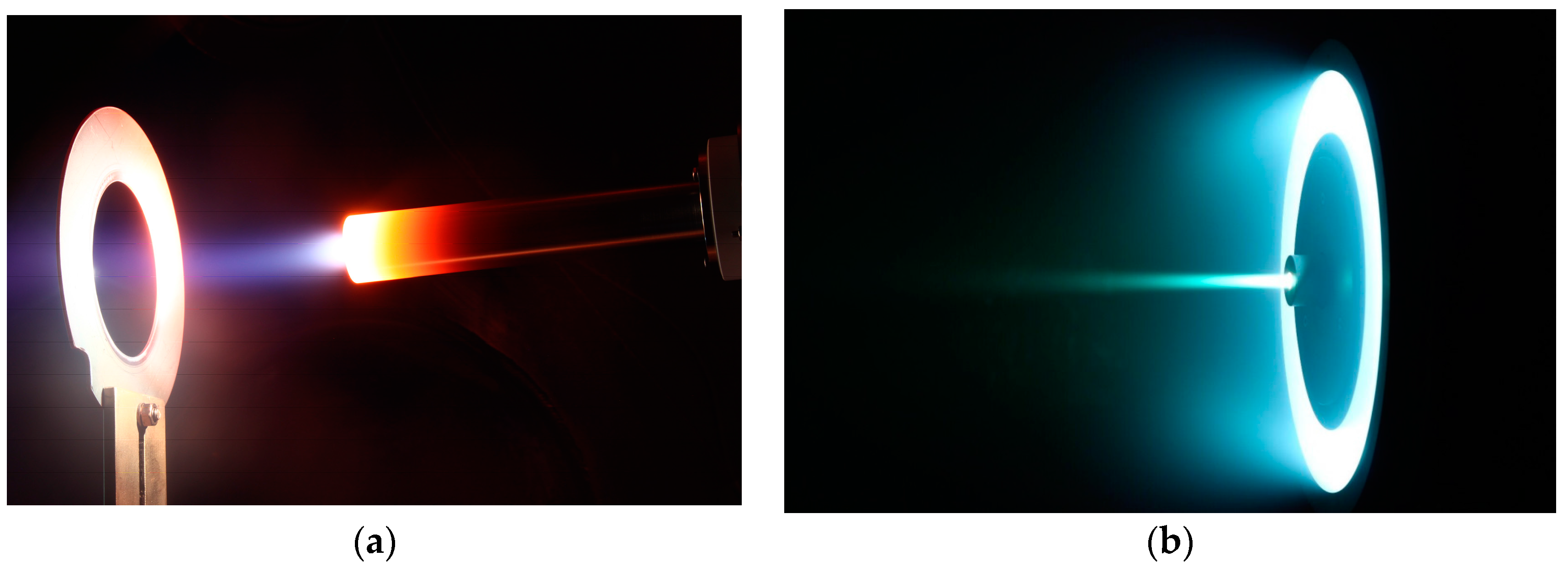
During the endurance test, the B-type thermocouple located in proximity to the active zone on the outer cathode tube surface measured a temperature of 1168 ± 3 °C. The corresponding value computed from the numerical model is 1530 °C, thus a discrepancy of about 27% exists. However, the discrepancy may be affected by a non-perfect contact of the thermocouple with the tube. As a matter of fact, the second B-type thermocouple located 29 mm upstream of the first one measured a temperature of 1114 ± 3 °C, which is in good agreement with the theoretical value of 1035 °C (discrepancy of about 7%). Figure 13 shows HC20 with the Sitael 5 kW Hall thruster HT5k, during operation with xenon propellant.
4.2. HC60
A hollow cathode has been developed to be coupled with HT20k, a 20 kW-class Hall thruster recently developed at Sitael [19]. The HC60 cathode has been designed to operate at mass flow rates between 2 and 5 mg/s, at discharge currents between 30 and 60 A. A 200 W-class heater can be included in the cathode assembly. The cathode predicted lifetime is higher than 104 h.
4.2.1. Experimental Setup
During the cathode stand-alone test campaign, an external anode plate was located 100 mm downstream of the keeper orifice section. A current-limited Magna-Power TSD 1000-15 (1000 V, 15 A, 15 kW) power supply controlled the cathode-to-keeper voltage during discharge initiation, and the current during operation. The cathode-to-anode current was controlled using a Regatron AG TopCon TC.P.20.500.400.S (500 V, 50 A, 20 kW, Rorschach, Switzerland) power supply. The heater current was controlled by using a Sorensen DLM 300-3.5E (300 V, 3.5 A). The power supplies were connected to a common negative reference and the setup was electrically floating with respect to ground. The gas feeding system was equipped with a Bronkhorst F-201C-FAC-22-V mass flow controller. High purity (grade N48) xenon and krypton were used during the test campaigns. K-type thermocouples were installed at the cathode mechanical interface, to monitor the integrity of the materials during extended operation.
4.2.2. Cathode Performance
The cathode pressure at room conditions was measured with both xenon and krypton, with the values reported in Figure 14. At a given mass flow rate, the pressure with krypton is higher with respect to xenon, due to lower atomic mass of krypton. In its heaterless configuration, the cathode was ignited with a keeper voltage between 800 and 950 V, with a mass flow rate of 12 mg/s. The keeper current was limited to 15 A. With a heating power of about 170 W, the cathode was ignited with a mass flow rate of 5 mg/s, at a keeper voltage in the range between 450 and 500 V. The ignition parameters showed no significant variations with both xenon and krypton.
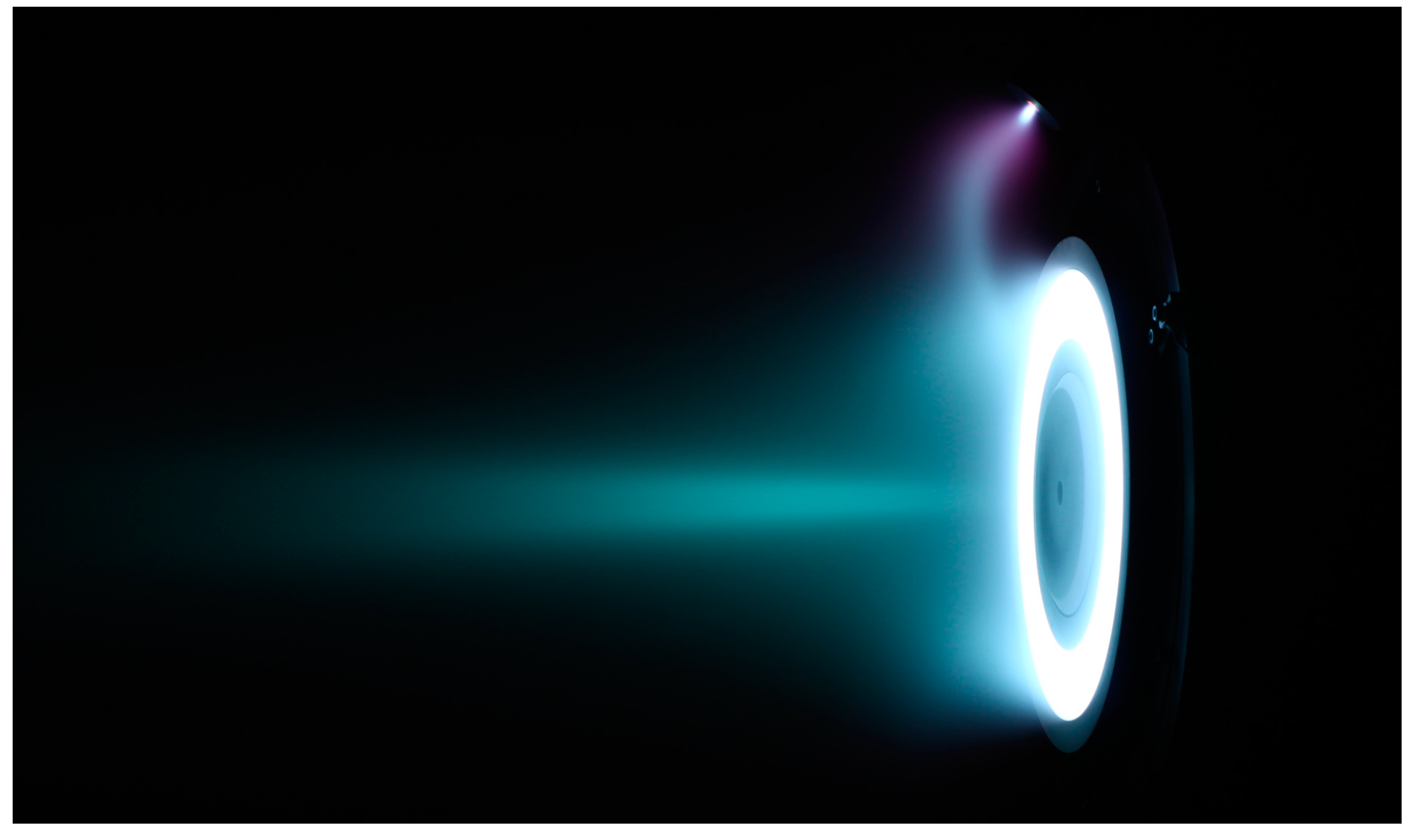
The cathode was firstly operated with the keeper only, in the range of current 11–15 A, at mass flow rates between 3 and 5 mg/s. The collected data are shown in Figure 15a, in terms of electrical characteristics for the cathode fed with xenon. Similar results were obtained with krypton, as shown in Figure 15b. Nevertheless, the cathode presented a stable operation in a smaller number of points, as compared with xenon propellant, likely due to the higher ionization energy of krypton (about 14 eV) with respect to xenon (about 12 eV). The cathode was tested with xenon at a total current up to 60 A (50 A anode current, 10 A keeper current), in the considered range of mass flow rate 3–5 mg/s. The operation with krypton required a mass flow rate of at least 5 mg/s to run the cathode in triode mode with the anode. At 6 mg/s Kr, the lowest keeper current which allowed for sustaining a discharge of 30–50 A at the anode was 2 A. As a matter of fact, the cathode was not able to operate in diode mode with the anode with krypton, whereas an anode current of 50 A with keeper off was sustained with xenon, at 4 mg/s. The electrical characteristic computed with the aid of the numerical code, at 5 mg/s Xe, is shown in Figure 16. The theoretical results can be compared with the measured anode voltages of about 16.5 V, for a current sweep from 30 to 50 A, even though the model does not compute any potential drop downstream of the keeper orifice. Figure 17 shows the cathode during the operation with keeper and anode (a), and during the coupling test with HT20k (b).
5. Conclusions
Several hollow cathodes conceived for Hall effect thrusters with a wide range of power levels have been developed and tested at Sitael. In particular, the cathodes were conceived for Hall thrusters belonging to the following power classes: 100 W, 400 W, 5 kW, and 20 kW. The respective current ranges considered in the cathode design are 0.3–1, 1–3, 8–20, and 30–60 A. The cathode ignition was investigated, showing that a heaterless configuration implies keeper voltages as high as 950 V to start the cathode. The keeper voltage at ignition can be lowered down to 300 V by including a heater in the cathode assembly. The cathodes were tested both in stand-alone configuration and coupled with the thrusters, including several characterizations with krypton propellant. The results are promising and in good accordance with both experimental data available in the literature and the theoretical predictions coming from the in-house developed model. Future activities will include additional coupling tests with the thrusters, long-duration campaigns, and a study of the influence of the heater power on the LaB6 cathodes ignition. A more extensive comparison between theoretical and experimental data will be also carried out to deeply validate the numerical model.
Acknowledgments
The authors gratefully acknowledge the contribution of Stefan Gregucci, Alexej Hock, Cosimo Ducci, Federico Cannelli, Carlo Tellini, Ugo Cesari, Nicola Giusti, Luca Pieri, and Paolo Balducci for the laboratory activities.
Author Contributions
Daniela Pedrini performed the numerical simulations, took part in the experiments, and prepared the manuscript. Tommaso Misuri, Fabrizio Paganucci, and Mariano Andrenucci guided and supervised the activities, and revised the manuscript.
Conflicts of Interest
The authors declare no conflict of interest.
References
- Goebel, D.M.; Jameson, K.K.; Hofer, R.R. Hall Thruster Cathode Flow Impact on Coupling Voltage and Cathode Life. J. Propuls. Power 2012, 28, 355–363. [Google Scholar] [CrossRef]
- Albertoni, R.; Andrenucci, M.; Pedrini, D.; Paganucci, F. Preliminary Characterization of a LaB6 Hollow Cathode for Low-Power Hall Effect Thrusters. In Proceedings of the 33rd International Electric Propulsion Conference, Washington, DC, USA, 6–10 October 2013. [Google Scholar]
- Oleson, S.; Meyer, R. Launch Vehicle and Power Level Impacts on Electric GEO Insertion. In Proceedings of the 32nd Joint Propulsion Conference, Washington, DC, USA, 1–3 July 1996; pp. 1996–2978. [Google Scholar]
- Goebel, D.M.; Katz, I. Fundamentals of Electric Propulsion: Ion and Hall Thrusters; John Wiley and Sons: Hoboken, NJ, USA, 2008; pp. 243–323. [Google Scholar]
- Coletti, M.; Gabriel, S. Barium Oxide Depletion from Hollow-Cathode Inserts: Modeling and Comparison with Experiments. J. Propuls. Power 2010, 26, 364–369. [Google Scholar] [CrossRef]
- Domonkos, M.T. Evaluation of Low-Current Orificed Hollow Cathodes. Ph.D. Thesis, The University of Michigan, Ann Arbor, MI, USA, 1999. [Google Scholar]
- Pedrini, D.; Albertoni, R.; Paganucci, F.; Andrenucci, M. Theoretical Model of a Lanthanum Hexaboride Hollow Cathode. IEEE Trans. Plasma Sci. 2014, 43, 209–217. [Google Scholar] [CrossRef]
- Pedrini, D.; Cannelli, F.; Ducci, C.; Misuri, T.; Paganucci, F.; Andrenucci, M. Hollow Cathodes Development at Sitael. In Proceedings of the Space Propulsion 2016, Marriott Park Hotel, Rome, Italy, 2–6 May 2016. [Google Scholar]
- Lafferty, J.M. Boride Cathodes. J. Appl. Phys. 1951, 22, 299–309. [Google Scholar] [CrossRef]
- Yamauchi, H.; Takagi, K.; Yuito, I.; Kawabe, U. Work Function of LaB6. Appl. Phys. Lett. 1976, 29, 638–640. [Google Scholar] [CrossRef]
- Pedrini, D.; Albertoni, R.; Paganucci, F.; Andrenucci, M. Modeling of LaB6 Hollow Cathode Performance and Lifetime. Acta Astronaut. 2015, 106, 170–178. [Google Scholar] [CrossRef]
- Lev, D.R.; Emsellem, G.D.; Hallock, A.K. The Rise of the Electric Age for Satellite Propulsion. New Space 2017, 5, 4–14. [Google Scholar] [CrossRef]
- Misuri, T.; Ducci, C.; Albertoni, R.; Andrenucci, M.; Pedrini, D. Sitael Low Power Hall Effect Thrusters for Small Satellites. In Proceedings of the Joint Conference of 30th International Symposium on Space Technology and Science, 34th International Electric Propulsion Conference and 6th Nano-satellite Symposium, Hyogo-Kobe, Japan, 4–10 July 2015. [Google Scholar]
- Ducci, C.; Albertoni, R.; Andrenucci, M. HT100D Performance Evaluation and Endurance Test Results. In Proceedings of the 33rd International Electric Propulsion Conference, Washington, DC, USA, 6–10 October 2013. [Google Scholar]
- Williams, G.; Smith, T.; Domonkos, M.; Shand, K.; Gallimore, A.; Drake, R. Laser Induced Fluorescence Characterization of Ions Emitted from a Hollow Cathode. In Proceedings of the 35th AIAA/ASME/SAE/ASEE Joint Propulsion Conference and Exhibit, Los Angeles, CA, USA, 20–24 June 1999; pp. 1–16. [Google Scholar]
- Ducci, C.; Andreussi, T.; Arkhipov, A.; Passaro, A.; Andrenucci, M.; Bulit, A.; Edwards, C. Investigation of a 5 kW Class Hall-Effect Thruster Operating with Different Xenon-Krypton Mixtures. In Proceedings of the Joint Conference of 30th International Symposium on Space Technology and Science, 34th International Electric Propulsion Conference and 6th Nano-satellite Symposium, Hyogo-Kobe, Japan, 4–10 July 2015. [Google Scholar]
- Brophy, J.; Brinza, D.; Polk, J.; Henry, M. The DS1 Hyper-Extended Mission. In Proceedings of the 38th Joint Propulsion Conference, Indianapolis, IN, USA, 8 July 2002. [Google Scholar]
- Fearn, D.; Patterson, S. Characterisation of the High Current Hollow Cathode for the T6 Ion Thruster. In Proceedings of the 34th AIAA/ASME/SAE/ASEE Joint Propulsion Conference and Exhibit, Cleveland, OH, USA, 13–15 July 1998. [Google Scholar]
- Leporini, A.; Giannetti, V.; Andreussi, T.; Pedrini, D.; Rossodivita, A.; Piragino, A.; Andrenucci, M.; Estublier, D. Development of a 20 kW Class Hall Effect Thruster. In Proceedings of the Space Propulsion 2016, Rome, Italy, 2–6 May 2016. [Google Scholar]
Figure 1.
General schematic of an orificed hollow cathode.

Figure 2.
Comparison of the measured and computed HC1 internal pressure: (a) Room conditions; (b) Cathode operating with 1 A keeper current.
Figure 2.
Comparison of the measured and computed HC1 internal pressure: (a) Room conditions; (b) Cathode operating with 1 A keeper current.
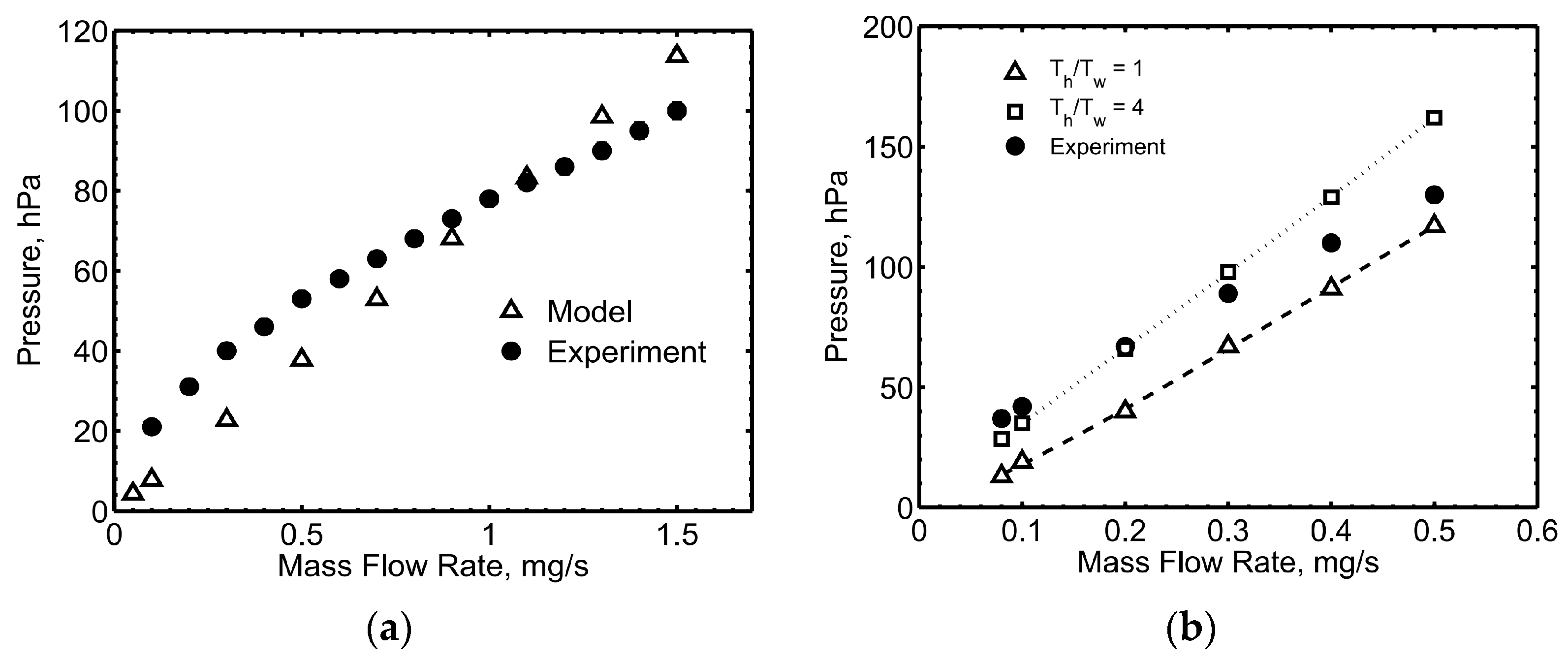
Figure 3.
(a) Electrical characteristics of HC1 in diode mode with the keeper alone; (b) Comparison of the electrical characteristic with the theoretical results, at 0.08 mg/s Xe.
Figure 3.
(a) Electrical characteristics of HC1 in diode mode with the keeper alone; (b) Comparison of the electrical characteristic with the theoretical results, at 0.08 mg/s Xe.

Figure 4.
HC1 electrical characteristics comparison with and without a heater, at 0.1 mg/s Xe.

Figure 5.
(a) HC1 operating with keeper and anode (keeper current 1 A, anode current 0.9 A, 1 mg/s Xe); (b) HC1 operating with the HT100D thruster.
Figure 5.
(a) HC1 operating with keeper and anode (keeper current 1 A, anode current 0.9 A, 1 mg/s Xe); (b) HC1 operating with the HT100D thruster.
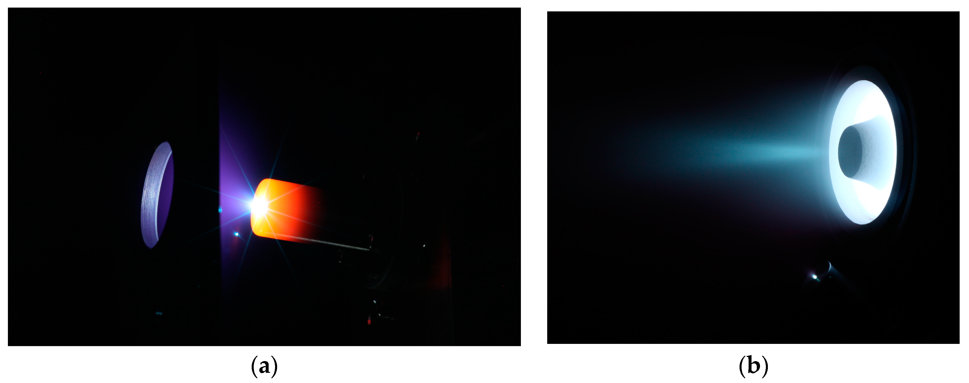
Figure 6.
Comparison of the measured and computed HC3 internal pressure: (a) Room conditions; (b) Cathode operating with 3 A keeper current.
Figure 6.
Comparison of the measured and computed HC3 internal pressure: (a) Room conditions; (b) Cathode operating with 3 A keeper current.

Figure 7.
Electrical characteristics of HC3 operating with the keeper alone: (a) AR = 1.2; (b) AR = 0.9.
Figure 7.
Electrical characteristics of HC3 operating with the keeper alone: (a) AR = 1.2; (b) AR = 0.9.

Figure 8.
Comparison of electrical characteristics of HC3 with the theoretical results: (a) 0.08 mg/s Xe; (b) 0.1 mg/s Xe.
Figure 8.
Comparison of electrical characteristics of HC3 with the theoretical results: (a) 0.08 mg/s Xe; (b) 0.1 mg/s Xe.
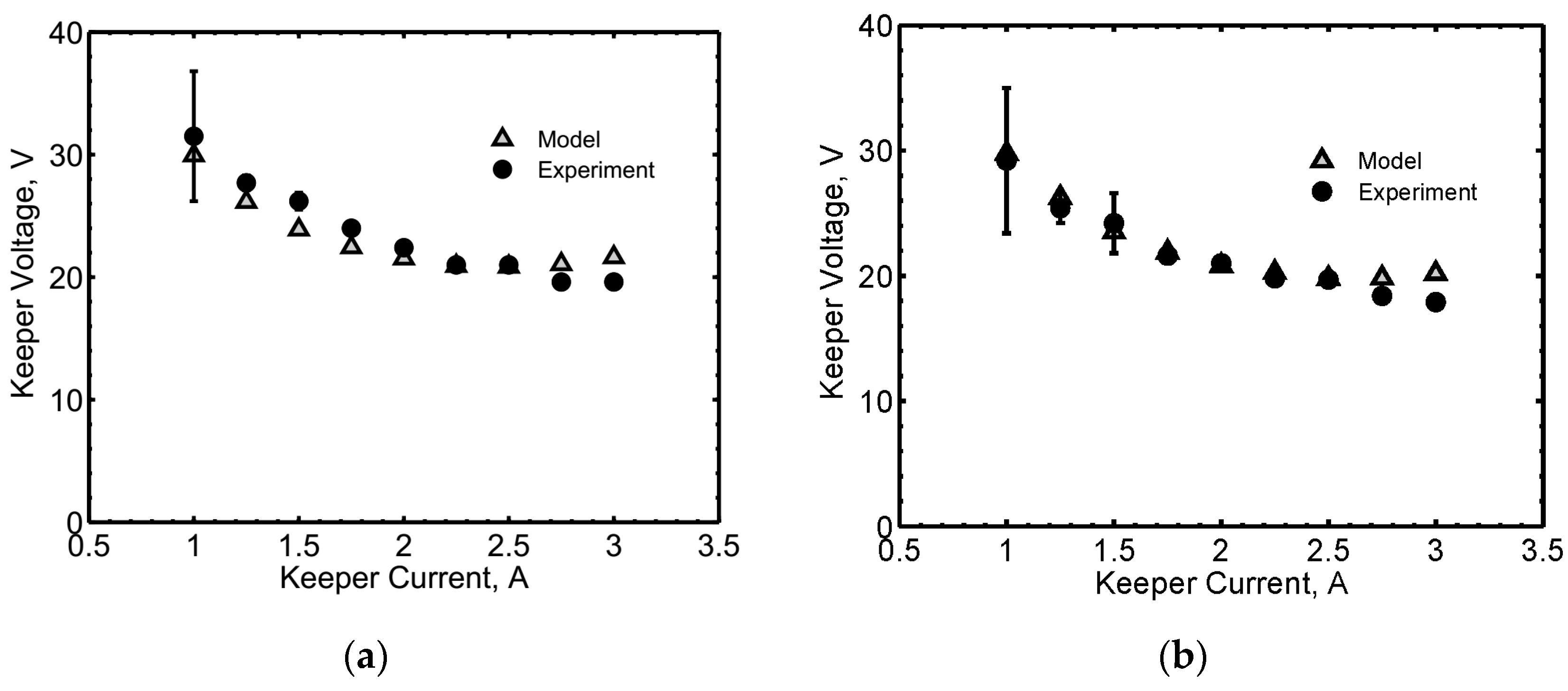
Figure 9.
HC3 during operation with HT100D.

Figure 10.
HC20 characterization at 1 mg/s Xe and 2 A keeper current: (a) Keeper voltage vs. anode current; (b) Anode voltage vs. anode current.
Figure 10.
HC20 characterization at 1 mg/s Xe and 2 A keeper current: (a) Keeper voltage vs. anode current; (b) Anode voltage vs. anode current.
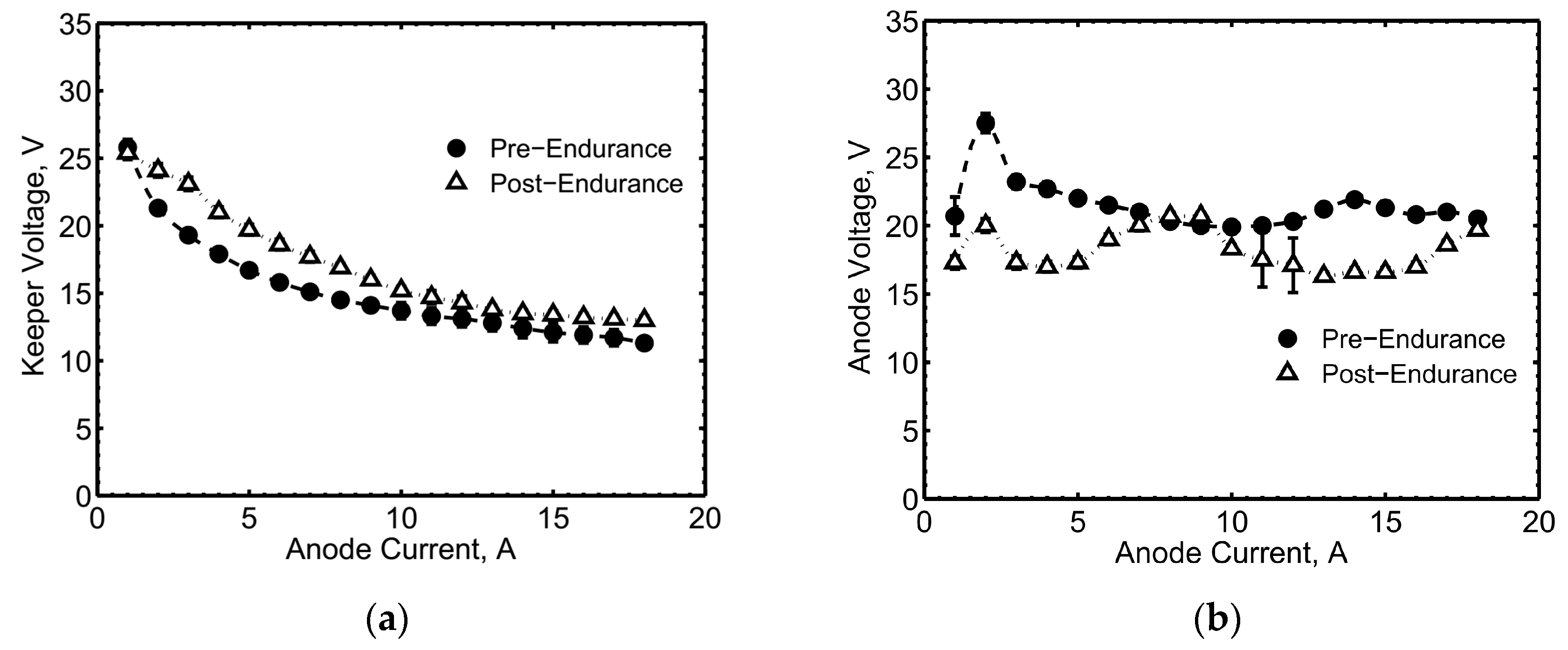
Figure 11.
HC20 post-endurance characterization with krypton, at 2 A keeper current and different mass flow rates: (a) Keeper voltage vs. anode current; (b) Anode voltage vs. anode current.
Figure 11.
HC20 post-endurance characterization with krypton, at 2 A keeper current and different mass flow rates: (a) Keeper voltage vs. anode current; (b) Anode voltage vs. anode current.

Figure 12.
Comparison of the HC20 experimental and theoretical electrical characteristics in triode mode at 2 A keeper current and 1 mg/s: (a) Xenon; (b) Krypton.
Figure 12.
Comparison of the HC20 experimental and theoretical electrical characteristics in triode mode at 2 A keeper current and 1 mg/s: (a) Xenon; (b) Krypton.
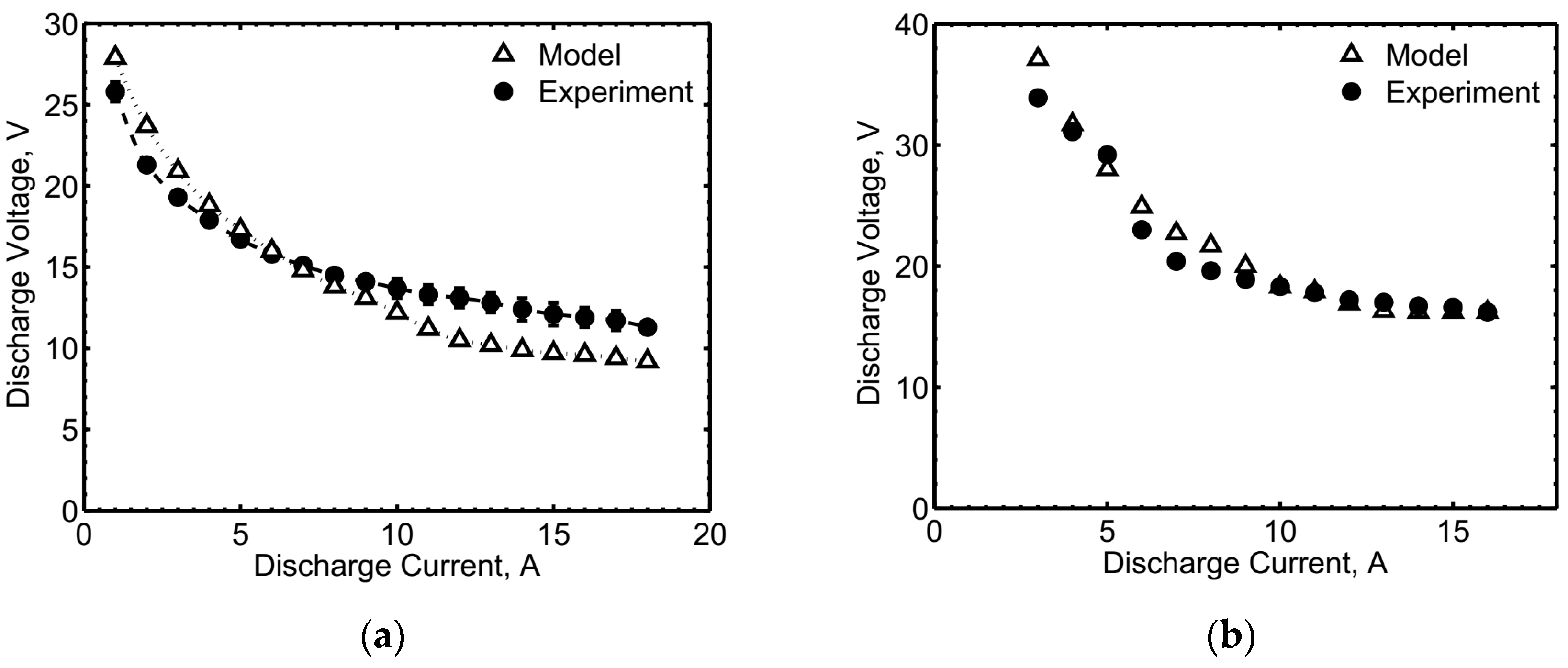
Figure 13.
HC20 during operation with HT5k.

Figure 14.
HC60 pressure at room conditions (Xe and Kr).
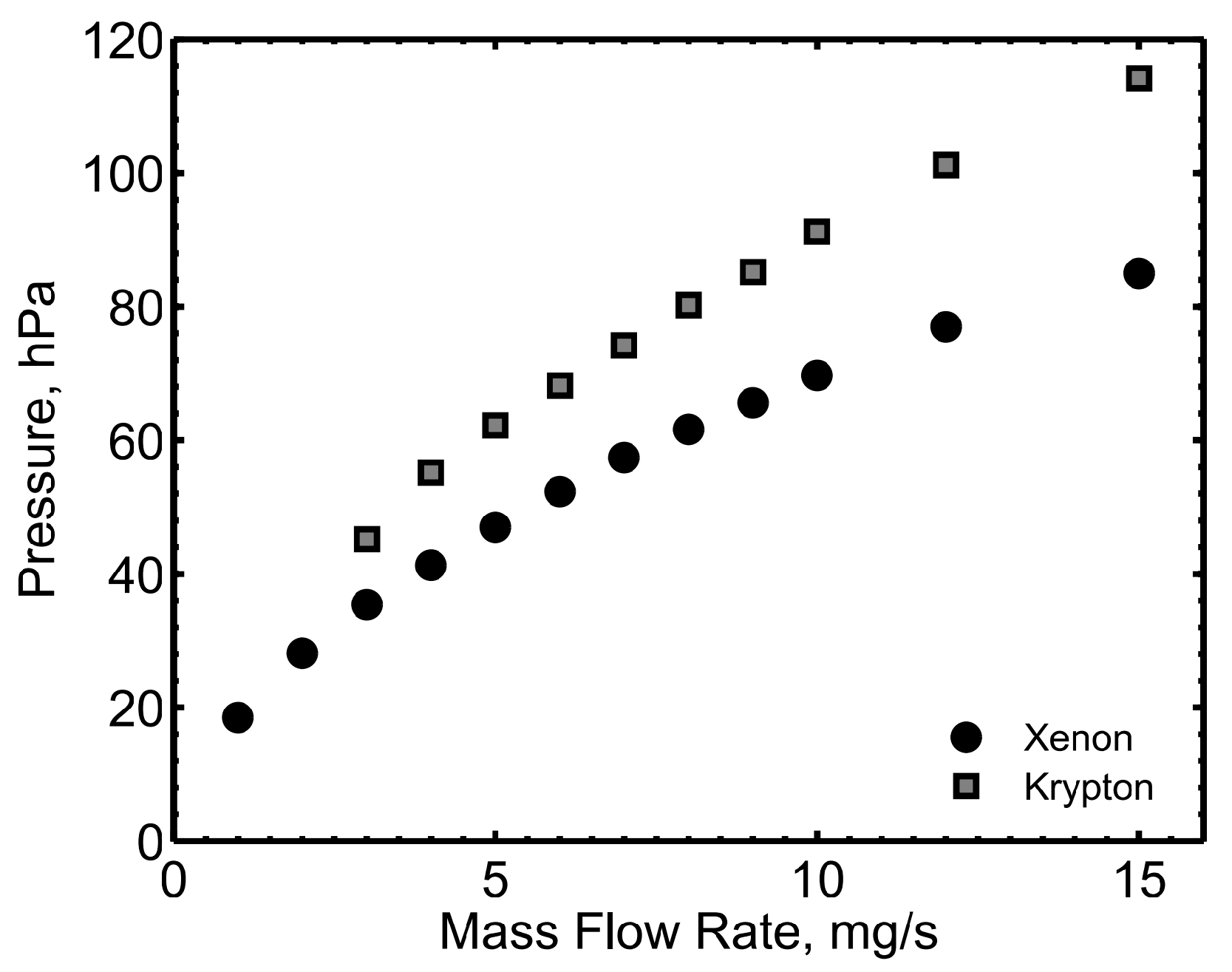
Figure 15.
Electrical characteristics of HC60 operating with the keeper alone at different mass flow rates: (a) Xenon; (b) Krypton.
Figure 15.
Electrical characteristics of HC60 operating with the keeper alone at different mass flow rates: (a) Xenon; (b) Krypton.
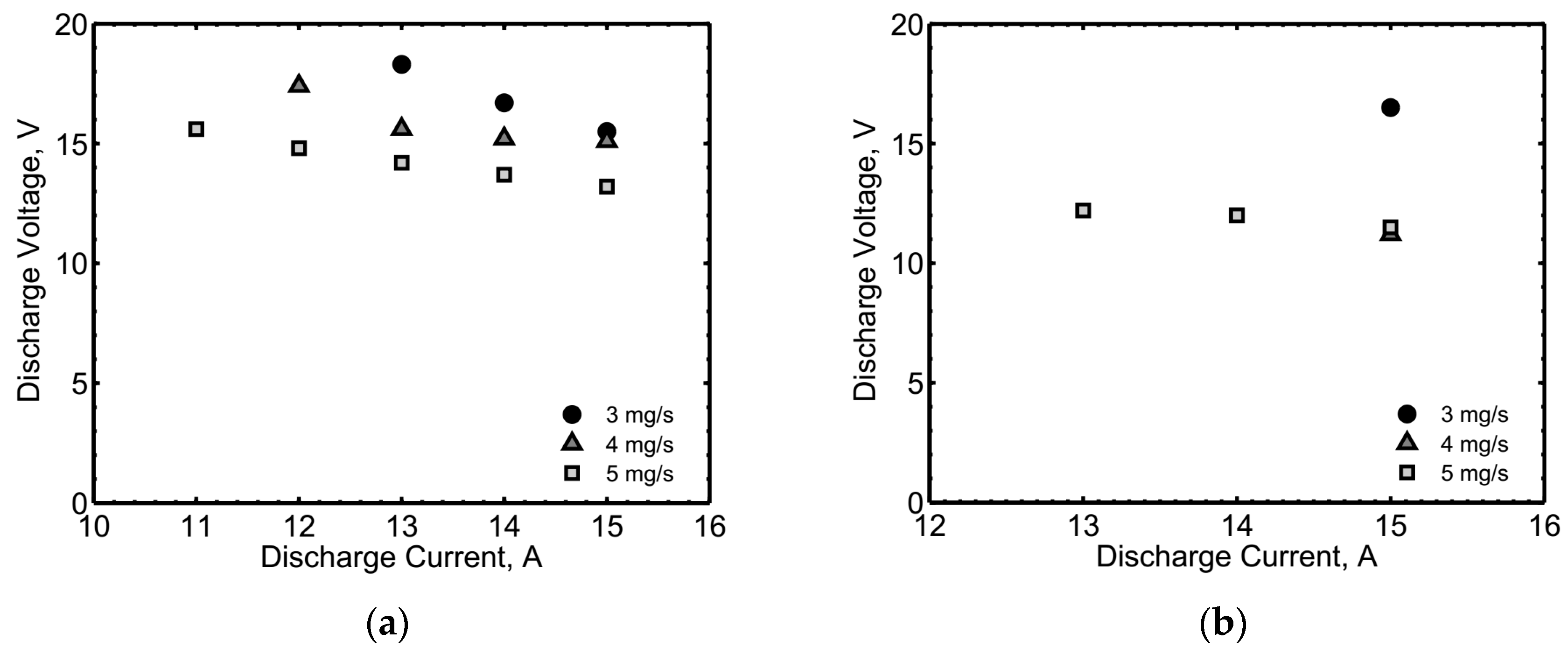
Figure 16.
HC60 experimental and theoretical electrical characteristics with the anode operating and the keeper off at 5 mg/s Xe.
Figure 16.
HC60 experimental and theoretical electrical characteristics with the anode operating and the keeper off at 5 mg/s Xe.

Figure 17.
HC60 during operation: (a) With 10 A keeper current, 38 A anode current, 3 mg/s Xe; (b) Coupled with the thruster HT20k, operating with xenon.
Figure 17.
HC60 during operation: (a) With 10 A keeper current, 38 A anode current, 3 mg/s Xe; (b) Coupled with the thruster HT20k, operating with xenon.

© 2017 by the authors. Licensee MDPI, Basel, Switzerland. This article is an open access article distributed under the terms and conditions of the Creative Commons Attribution (CC BY) license (http://creativecommons.org/licenses/by/4.0/).
Share and Cite
MDPI and ACS Style
Pedrini, D.; Misuri, T.; Paganucci, F.; Andrenucci, M. Development of Hollow Cathodes for Space Electric Propulsion at Sitael. Aerospace 2017, 4, 26. https://doi.org/10.3390/aerospace4020026
AMA Style
Pedrini D, Misuri T, Paganucci F, Andrenucci M. Development of Hollow Cathodes for Space Electric Propulsion at Sitael. Aerospace. 2017; 4(2):26. https://doi.org/10.3390/aerospace4020026
Chicago/Turabian StylePedrini, Daniela, Tommaso Misuri, Fabrizio Paganucci, and Mariano Andrenucci. 2017. "Development of Hollow Cathodes for Space Electric Propulsion at Sitael" Aerospace 4, no. 2: 26. https://doi.org/10.3390/aerospace4020026
Note that from the first issue of 2016, this journal uses article numbers instead of page numbers. See further details here.