
Air Traffic Security: Aircraft Classification Using ADS-B Message’s Phase-Pattern


Department of Electronic Engineering, University of Rome “Tor Vergata”, via del Politecnico 1, 00133 Rome, Italy
*
Author to whom correspondence should be addressed.
†
Current address: Rheinmetall Italia, Via Affile 102, 00131 Rome, Italy.
Aerospace 2017, 4(4), 51; https://doi.org/10.3390/aerospace4040051
Submission received: 27 September 2017
/
Revised: 20 October 2017
/
Accepted: 27 October 2017
/
Published: 30 October 2017
(This article belongs to the Special Issue Feature Papers in Aerospace)
Abstract
:Automatic Dependent Surveillance-Broadcast (ADS-B) is a surveillance system used in Air Traffic Control. With this system, the aircraft transmits their own information (identity, position, velocity, etc.) to any equipped listener for surveillance scope. The ADS-B is based on a very simple protocol and does not provide any kind of authentication and encryption, making it vulnerable to many types of cyber-attacks. In the paper, the use of the airplane/transmitter carrier phase is proposed as a feature to perform a classification of the aircraft and, therefore, distinguish legitimate messages from fake ones. The feature extraction process is described and a classification method is selected. Finally, a complete intruder detection algorithm is proposed and evaluated with real data.
1. Introduction
The Automatic Dependent Surveillance-Broadcast (ADS-B) system is one of the pillars of the Future Air Traffic Systems [1,2] and estimates suggest that about 80% of all commercial aircraft are now equipped with the ADS-B hardware [3]. It is a dependent and cooperative surveillance system used in Air Traffic Control (ATC) in which aircraft periodically transmit their own information such as identity, position, velocity, etc. to any equipped listener for surveillance scope [4]. The operational block diagram of this system is reported in Figure 1.
The equipped aircraft utilizes the on-board navigation system (i.e., the Global Positioning System-GPS-unit) to calculate its position and its velocity and then broadcasts this information on a common Radio Frequency (RF) channel using an on board emitter called . These information are received by any equipped aircraft and used to compose traffic information on the Cockpit Display. Similarly, a ground-based receiver is used in the ATC center to produce an image of the traffic on the controller’s display.
ADS-B system has various advantages compared to the classical radar surveillance: the biggest ones are the easy implementation, the low-cost hardware and the very high accuracy of position data. It also has some important disadvantages which include the dependency on the satellite navigation system (that could be corrupted, damaged or interfered) and the simple “free to air” protocol.
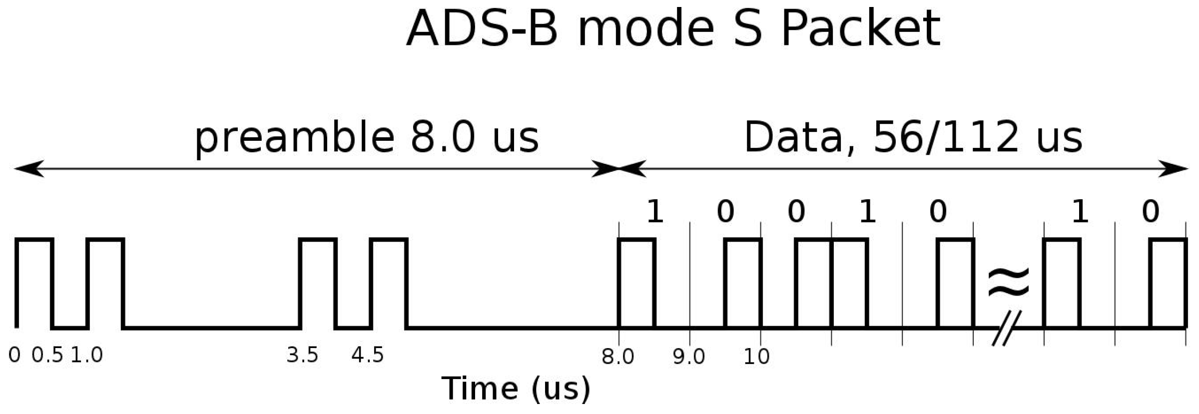
In fact, in commercial applications, the ADS-B system uses a data-link protocol called “1090 Extended Squitter (1090ES)” that is an evolution of the old Identification Friend or Foe (IFF) Secondary Surveillance Radar (SSR) signals [3,4]. Each aircraft periodically transmits messages to any equipped listener; the messages use Pulse Position Modulation (PPM) on L-band (1090 MHz) and they are sent with random access to the channel. Each message is composed of a preamble of four pulses and a data-block of 112 pulses where the information are coded with a 24-bit Cyclic Redundancy Check (CRC) [4,5]. Every message also contains a 24-bit unique identifier of the transponder (i.e., the unique identifier of the aircraft) called ICAO address [4]; in Figure 2 the format of the ADS-B message is reported. Various types of messages, with different data rates, can be coded and sent, such as: Aircraft Identification, Surface Position, Airborne Position (with Baro Altitude or with GPS Altitude), Airborne Velocities, etc. The transmission rate ranges from 2 msg/s to 0.2 msg/s depending on the message type.
The ADS-B protocol was introduced about two decades ago and cyber-attacks with RF manipulation of the communication were not considered as easy as they are nowadays. For this reason, the ADS-B protocol does not offer any encryption and authentication method. Thanks to the advent of cheap and accessible software-defined radios, today, RF attacks are possible using a widely available hardware and software, as recently illustrated for example in [6,7,8]. Examples of possible attacks to the ADS-B RF channel are:
- Eavesdropping, i.e., listening to the unsecured broadcast transmissions: it is impossible to be prevented without applying encryption and, of course, it is impossible to be detected;
- Jamming, i.e., the intentional transmission of high power harmful signals in the RF channel in order to disable the air–ground communication: for a single receiver or in a particular geographical area, this type of attack may create denial-of-service problems at any airport;
- Message injection (or spoofing), i.e., the intentional transmission of signals with the same protocol but with misleading information;
- Message deletion by SSR reply Garbling: legitimate messages can be “deleted” or manipulated by the superposition of false message with higher power.
In literature (e.g., in [9,10]), it is possible to find some proposals to introduce encryption and authentication on the ADS-B protocol to overcome eavesdropping and message injection attack. Multilateration is also proposed as a very efficient integrity check for ADS-B position data (see, for example, [11,12,13]). Jamming and message deletion vulnerabilities cannot be reduced with encryption or multilateration and are closely related to the ADS-B receiver hardware and software implementations that are developed according to the international “standards” or “recommendations” and require particular anti-jamming techniques implemented in the receiver (see for example [7]).
Here, we will focus on False Aircraft Injection, that is, the specific vulnerability of the ADS-B data link related to the previous mentioned message injection: by injecting false messages, it is possible to create non-existing aircraft and any ADS-B receiver will consider these messages as real, leading pilots or controllers to a potentially dangerous situation. We propose a method to contrast this attack, without changing the ADS-B protocol, which is based on the use of an identification/classification technique called RF Fingerprinting. It is a well-known technique, used also in electronic warfare, that identifies wireless devices by extracting the unique features embedded in the electromagnetic waves emitted by the transmitter. These unique features arise from randomness in the manufacturing process such as the presence of analog components in the transmission chain, different hardware and software implementation of the same protocol, transmitter clock stability, etc. For example, in [14,15], methods that use amplitude and phase information of the transmitter turn-on transient are proposed, in [16], authors propose a method for RF fingerprinting using clock skew and, in [17], it is possible to find a general comparison of different RF fingerprinting methods.
Once particular features of the transmitter are discovered, it is possible to create a database (library) of trusted aircraft/transponders (or of classes of trusted transponders) containing these particular features. It will be possible to check if the received signal from a particular airplane has the expected features (i.e., it is generated from the same transmitter as the one recorded in the database) and, if not, raise an alarm.
Therefore, in order to perform the fingerprinting, it is mandatory to identify any feature of the transmitted signals that differs from one transponder to another and that is time-invariant.
We propose focusing the attention on the phase of the transmitter carrier along the message transmission. In the next section, we will describe this phase pattern feature and its extraction procedure. The characteristics of this feature and the identification of different aircraft classes using real ADS-B signals during a measurement campaign are reported in Section 3. In Section 4, a classification method for the different classes is introduced and, in Section 5, an autonomous algorithm for intruder detection is proposed and evaluated.
2. Estimation of the ADS-B Message’s Phase-Pattern
Consider the 1090ES data link format reported in Figure 2: the PPM modulation implies that, neglecting the preamble, the Data-Block is always composed of pulses with different time positions to encode the information to be transmitted (i.e., Manchester coding) [4,18].
The transmitted signal (considering only the data-block) can be represented as follows:
where A is the message amplitude, is the bits sequence to be transmitted (composed of bits), is the carrier frequency equal to 1090 MHz and T is the pulse width equal to 0.5 s. Considering that the International Civil Aviation Organization (ICAO) standards [4,18] allow the manufacturers to develop transmitting devices with some tolerances on the various parameters, e.g.,
- central frequency could be MHz;
- the pulse should have width s, rise time 0.05 s 0.1 s and decay time 0.05 s 0.2 s;
- the Amplitude of the message could change within dB;
- no restrictions exist concerning the carrier phase due to the fact that all the information is coded in the amplitude of the signal.
Therefore, Equation (1) becomes:
where is the message amplitude, is the allowed jitter of the carrier frequency, T is the pulse width equal to 0.5 s, and is a function that represents the real shape of the transmitted pulse considering the specification on the and (see, for example, Figure 3). Finally, is the phase of the carrier.
Theoretically, on the receiver side, all of these signal features can be measured and used to classify the aircraft/transponder.
As mentioned before, the message carrier phase has no restrictions imposed by the ICAO standards. For this reason, it may be possible to find different phase patterns among transponders of different manufacturers; we will focus on the carrier phase behaviour inside the 112 s of transmitted Data-Block.
To estimate the phase, we assume using a 1090 MHz coherent receiver with neglectable phase error (w.r.t. the phase error of the transmitter). Assuming also an IF sampling of the signal and the presence of Additive White Gaussian Noise (AWGN), Equation (2) becomes:
where represents the noise and is the sampling time. We have assumed equal to zero the propagation delay from the transmitter to the receiver only to simplify the notation.
Remembering that, in the case of sampled sinusoidal signal with phase and frequency f, the Maximum Likelihood Estimator for the phase is given by [19]:
where K represents the available sinusoid samples, it is possible to estimate 112 different phase values , one for each pulse of the ADS-B message using the following formula:
where m identifies the pulse and K the relative pulse’s samples.
To perform this computation, it is mandatory to know:
- the time position of each pulse: it can be easily determined estimating the time of arrival of the message, with a preamble detection algorithm and then decoding the envelope of the received signal. This operation is already done by any ADS-B receiver [4];
- the central frequency of the message (it may also include the Doppler frequency due to the airplane velocity): it can be done using any kind of frequency estimator such as finding the max value of the Discrete Fourier Transform of the received signal.
Finally, without loss of generality, we can refer all the phases to the first pulse and we can apply a phase-unwrapping procedure to prevent phase ambiguity and to obtain the phase sequence .
The step by step process for the phase pattern extraction is reported in Algorithm 1.
| Algorithm 1: Phase pattern extraction. |
| Input: |
| Sampled IF signal |
| Steps: |
| 1. Envelope Computation (e.g., with Hilbert transformation); |
| 2. Preamble detection (as described in the ADS-B standards); |
| 3. Data Block decoding (as described in the ADS-B standards); |
| 4. Pulses time intervals estimation; |
| 5. central frequency estimation by finding the max of the DFT of the signal; |
| 6. For each of 112 pulses: Pulse’s carrier phase estimation by the use of (5); |
| 7. Phase unwrapping. |
| Output: |
| sequence |
We expect that depends on the transmitter peculiarities (such as stability of the oscillator, phase noise, transmitter clock, etc.). To be useful for fingerprinting, it must: (a) differ from transponder to transponder (or at least differ between different classes of transponders, e.g., vendor, hardware version, Firmware version, etc.); (b) be time-invariant for a long period (knowing that airplanes do not change/update their equipment so frequently). To verify these two characteristics, a measurement campaign with real data was done.
3. Real Data Analysis
A measurement campaign has been done in November 2016 using the Transponder Data Recorder (TDR). The TDR is a Mode S multi-channel receiver composed of four independent linear channels and one logarithmic channel. Each receiving channel is connected to an element of an array antenna. The linear channels downconvert the signals to intermediate frequency (IF) at 21.5 MHz and the logarithmic channel is based on the Analog Devices AD8313 log receiver with a base-band output.
The digital section is based on an NI platform composed of a controller (NI PXIe 8135, National Instruments, Austin, TX, USA), three acquisition cards (NI PXIe 5122, National Instruments, Austin, TX, USA) and an FPGA card (NI FlexRio PXIe7966, National Instruments, Austin, TX, USA). Each acquisition card has two input channels and a sample rate up to 100 Msamples/s [20]. Pictures of the TDR elements are reported in Figure 4.
The antenna has been installed on the Engineering Faculty roof for four consecutive days, receiving 660,182 messages sent by 676 different aircraft.
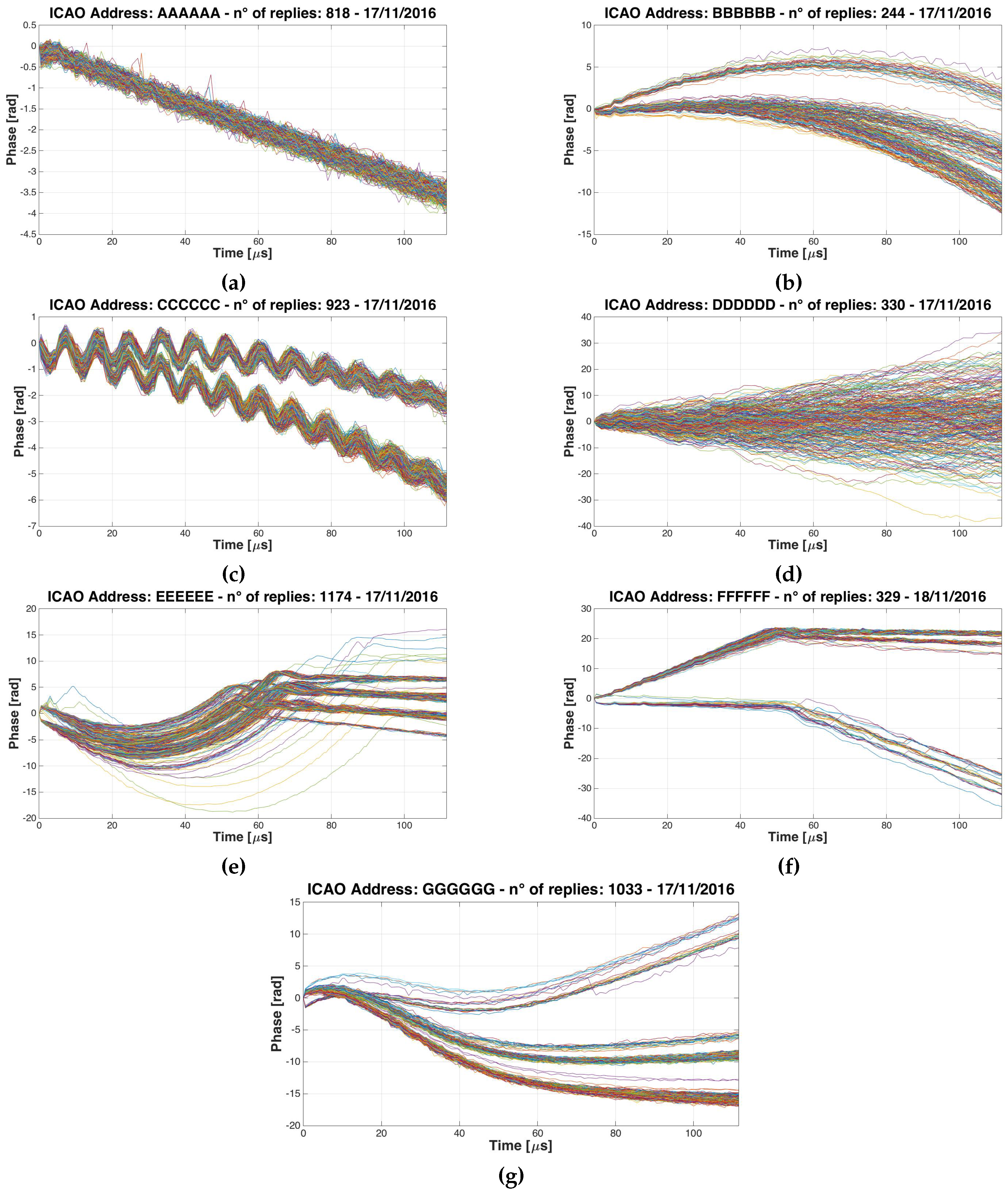
Examples of measured phase patterns, , are reported in Figure 5. For each graph, the phase patterns obtained from different messages coming from the same aircraft, are plotted. As expected, many airplanes do not have a particular phase pattern and different messages are uncorrelated to each other (see Figure 5d), but many others have very particular patterns (see Figure 5a–c,e–g). Seven different classes of patterns have been discovered: (a) Linear; (b) Quadratic; (c) Oscillating; (d) Non-Coherent; (e) Mixed: Quadratic+Linear; (f) Mixed: Linear+Linear and (g) Wave.
This result is important because, although standards and recommendations do not require any phase restriction, many real transponders use a precise oscillator to generate the ADS-B signal and different aircraft have different phase patterns.
We have classified (by inspection) all the replies received in the first two days. The classification results for the first day are summarized in Table 1: the airplanes that do not change their phase pattern class for all the day are about the 70% of the total amount. Most of these belong to the non coherent class followed by the linear ones and the quadratic ones. Results for the second day are quite similar to the first one.
Moreover, by comparing the received replies of the first two days, it has been discovered that there were 104 common aircraft (having the same ICAO address), 57 out of 104 (54.8%) were classifiable and 55 out of 57 (52.5% of the total) belonged to the same class of the day before.
In summary, we can affirm that at least the 50% of the observed aircraft are classifiable within the proposed classes and do not change their phase pattern in the time (at least for two consecutive days). It follows that the phase pattern can be used to classify the aircraft and to detect the presence of intruders if its phase pattern does not belong to the expected class.
In the following sections, we will show the results for all four of the days, using an automatic classification algorithm.
4. Aircraft Classification Method
In our particular application, the classification of the aircraft will be used to understand if the received signals are really generated from the expected aircraft or not; many methods are proposed in literature to solve this kind of problem [10,21]; each method has pros and cons with different performances for different applications.
In our case, we have chosen the Neural Network (NN) approach to maintain low the computational load and the memory usage [22,23].
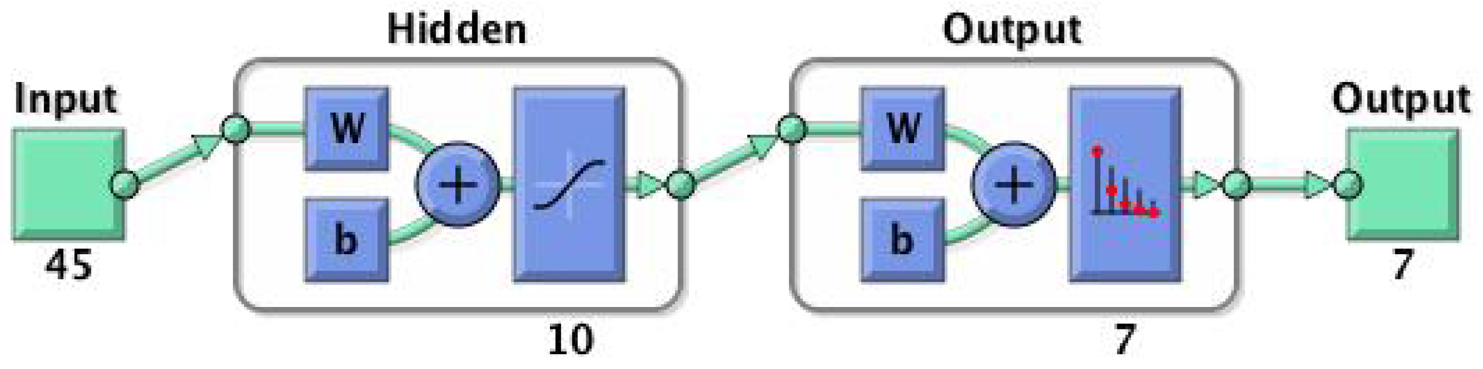
To successfully apply the classification, pre-elaboration of the phase pattern is needed to at least reduce the number of the NN input. First of all, it should be noted that the sequence is not homogeneously distributed in the time because the phase measures are made in the pulses of the ADS-B messages and the pulses change time position according to the PPM modulation. To overcome this problem, an interpolation has been used to evaluate the phase of the transmitter also in the time space (chip) where the pulse is not present, obtaining a new sequence composed of 224 elements. Afterwards, we have reduced the cardinality of the sequence with 5:1 decimation. The 45 elements of this new sequence has been used as an input of the NN. Various types of NN have been tested: we have chosen the NN represented in Figure 6. It has an Input layer of 45 elements (the cardinality of the sequence), a hidden layer with 10 elements and an output layer of seven elements (the number of the aircraft classes).
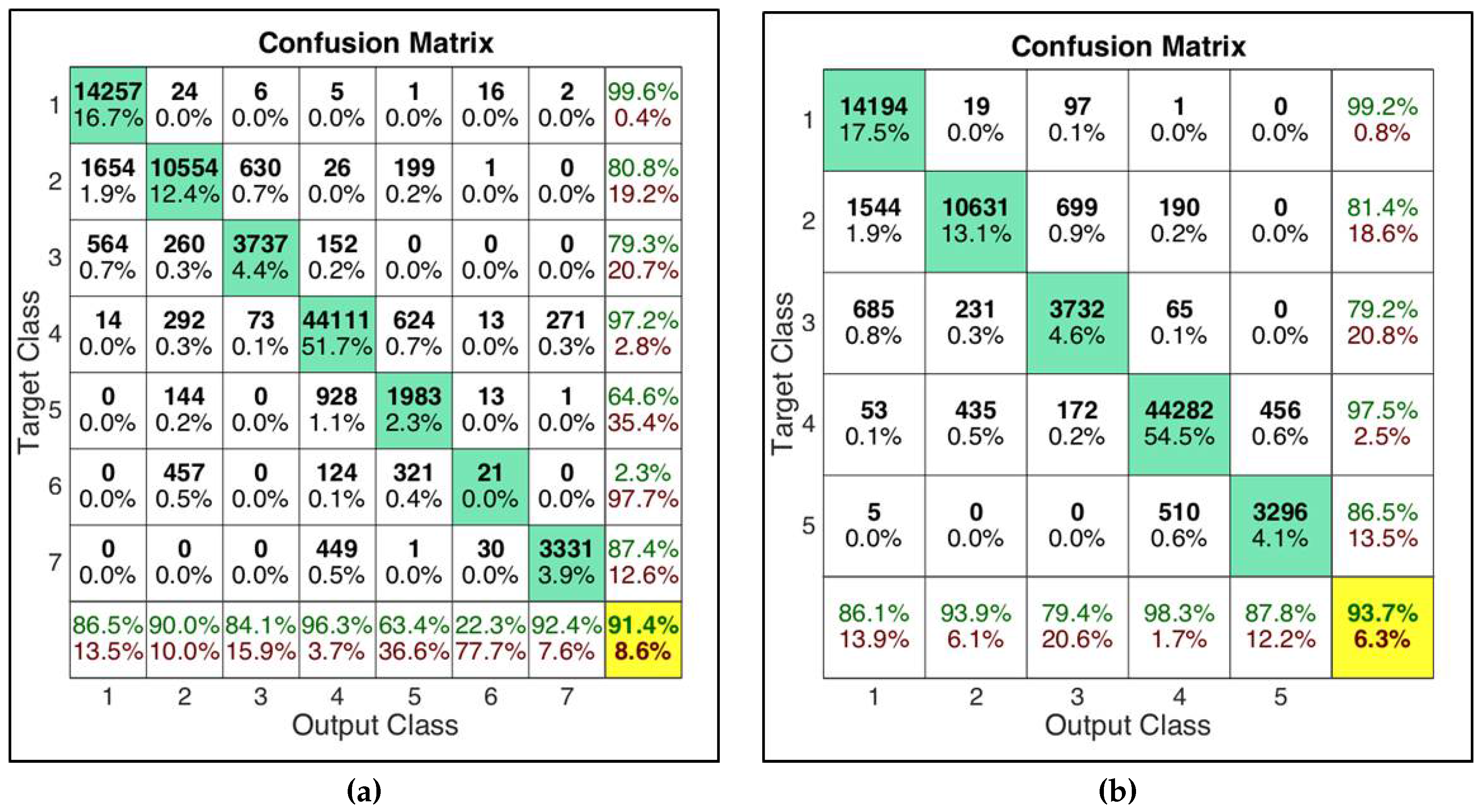
The NN has been trained with the data coming from the first day and validated with the data coming from the second day obtaining the results reported in Figure 7a; the 7 classes NN has a correct classification probability of 91.4%. The confusion matrix shows excellent performance for some classes (class 1 Linear and class 4 Non-Coherent) but bad results for five and six classes (mixed classes). For this reason and also considering the fact that the mixed classes are composed of a very small number of aircraft in the considered data set (see Table 1), we have decided to exclude mixed classes from the classification process implementing also a 5 classes NN, whose performances are shown in Figure 7b. Both networks will be used in the following analysis.
Summing up, we can assert that:
- More than 50% of the observed aircraft have a particular and representative phase pattern.
- The phase pattern can be used to classify the aircraft using an NN obtaining performances up to 93% (in terms of probability of correct classification).
In the next section, we will show how to use the proposed NN to detect the presence of an intruder in the 1090 MHz channel.
5. Intruder Detection Algorithm
As introduced before, we can use the aircraft class to detect the presence of an intruder by verifying the phase pattern of the received messages: if the phase pattern of the received signal does not belong to the expected class for the declared ICAO Address, an alarm has to be sent to the operator. To perform this task, it is necessary:
- To create and populate a Database with the assigned class for any legitimate and genuine aircraft: to perform this action, for each aircraft not yet present in the Database, messages are received and classified using the proposed NN. If more than messages are classified in the same class, the aircraft is assigned to that class. Otherwise, the aircraft is declared not classifiable and excluded from the test phase;
- To define a test to verify if the received messages come from the expected transmitter or from a fake one: for each aircraft in the Database, messages are received and classified and, if more than messages are classified in the wrong class, an alarm is raised. The logic is used to improve the probability of false alarm and the probability of detection of the classification method;
- To remove from the test phase the aircraft that do not have a constant phase pattern in the time: if an aircraft gives more than J consecutive alarms, the test phase for that aircraft is stopped. This last step is done to detect the aircraft that change their phase pattern after the Database population. These aircraft, in a real implementation, should be analyzed by an operator that can allow new classification attempts for the aircraft replacing the old one. It can be noted that the larger is, the lower is the probability to be in this situation.
The complete and detailed algorithms are reported in Algorithm 2.
| Algorithm 2: Intruder Detection. |
| Input: |
| ICAO Address and of the received ADS-B message |
Steps:
|
| Output: |
| Alarm |
The proposed algorithm has been evaluated using the real data obtained in the measurement campaign. In particular, the Probability of False Alarm and Probability of Detection, considering the possible configuration for an intruder, have been calculated. We can distinguish between three cases:
- Legitimate aircraft, no attack: a real aircraft transmits legitimate replies. ADS-B receiver will receive only real messages. This situation will be used to evaluate the False Alarm Probability.
- Legitimate aircraft not present but receiver under attack: a transmitter emulates the presence of an aircraft transmitting fake replies with a given ICAO address. The ADS-B receiver will receive only fake messages. This situation will be used to evaluate the Probability of Detection.
- Legitimate aircraft present and under attack: a transmitter emulates an aircraft transmitting fake replies with a given ICAO address. In the meantime, the legitimate aircraft is transmitting messages too. If the attacker transmits replies according to ADS-B protocols, the ADS-B receiver will receive interleaving fake and legitimate messages. This situation will be used to evaluate the Probability of Detection.
Moreover, we can distinguish between two types of attackers: (a) an attacker with general knowledge of the system and standards that implements a “transponder like” transmitter using a low cost general purpose Software Defined Radio (SDR) and (b) an attacker who uses a real commercial transponder, hacking it to change the transponder’s ICAO Address and to send fake messages with false information. The False Alarm Probability () is computed as the number of raised alarms over the total number of tests. The Detection Probability () is calculated as the number of detected attacks over the total number of simulated attacks.
The is supposed to not have deep knowledge of the ADS-B transmitter peculiarities. For this reason, the SDR signal has been simulated with zero phase shift without introducing any kind of carrier phase pattern. In general, a more learned attacker may also simulate the phase pattern of the attacked aircraft.
The has been simulated choosing a random real aircraft in the recorded signals and changing its ICAO address.
The obtained results are reported in Table 2. The results are obtained considering 660,182 ADS-B replies received from 676 different ICAO Addresses during the measurement campaign, : with , or and the number of needed consecutive alarms to stop the test phase of an aircraft is .
The upper part of Table 2 concerns the general classification performance of the intruder detection algorithm and can be compared with Table 1. It can be noted that the number of not classified aircraft depends only on parameter that rules the classification attempts. In any case, the proposed algorithm shows classification results similar to the visual inspection ones: the automatic method is able to assign about 62–64% of aircraft to one of the classes against the reported in Table 1.
In the lower part of the table, the intruder detection performances are reported. For both the NNs and both values of , the is about 3.6–3.8%. Also increasing , the performances, in terms of false alarm probability, do not improve: this could be due to the nature of the data and to the fact that some aircraft have changed their phase pattern during the four registration days.
Concerning the probability of detection, first of all, it must be noted that it is lower than the probability of correct classification of the NN (reported in Figure 7) because, in many cases, the attacker and the attacked aircraft belong to the same class and the intruder cannot be detected.
Furthermore, the parameter drives the performance of the system: using a value greater than , the detection probability is very low in case of intruder and aircraft both present; this happens because in this case about half of the received messages are from the real aircraft. However, in this specific case, another very simple test, such as position tracking algorithms, can be used to detect the intruder thanks to the contrasting information in legitimate and fake messages.
In general, better results are obtained with the 7 classes NN. This can be explained by two reasons: firstly, if the classification method works, the higher the number of the classes, the lower the probability that attacker and attacked aircraft signals belong to the same class; secondly, for the particular case of the SDR attack, using the 7 classes NN, the SDR signals belong to a very specific class containing a low number of real aircraft.
6. Conclusions
This work shows that it is possible to classify ADS-B transponders using the phase pattern of the transmitted signal. It was discovered, by real data analysis, that many real ADS-B transponders use a very stable oscillator that produces a specific phase pattern and that, using a Neural Network classifier, it is possible to distinguish seven different classes of aircraft. Moreover, these seven classes have been used to develop an automatic classification system that is able to assign with high reliability the aircraft to one of the classes. Finally, it was developed a method to detect intruders, exploiting that classification. Good results in terms of False Alarm Probability and Detection Probability for various threat configurations were obtained.
In the author’s opinion, the phase pattern, jointly with other transmitted signals’ characteristics (e.g., carrier frequency stability, pulse shapes, message timings, etc.) could be used for a more complex classification, providing a big improvement of ADS-B security.
Author Contributions
Mauro Leonardi proposed the idea and gave the theoretical support. Luca Di Gregorio implemented the Phase Pattern extraction in Matlab (Matlab R16b, MathWorks, Natick, MA, USA) and analyzed the results. Davide Di Fausto implemented the NN and the intruder detection algorithm and analyzed the results.
Conflicts of Interest
The authors declare no conflict of interest.
Abbreviations
The following abbreviations are used in this manuscript:
| ADS-B | Automatic Dependent Surveillance—Broadcast |
| ATC | Air Traffic Control |
| AWGN | Additive White Gaussian Noise |
| CRC | Cyclic Redundancy Check |
| DB | Database |
| DFT | Discrete Fourier Transform |
| ES | Extended Squitter |
| FPGA | Field Programmable Gate Array |
| GPS | Global Positioning System |
| HW | Hardware |
| ICAO | International Civil Aviation Organization |
| IF | Intermediate Frequency |
| IFF | Identification Friend or Foe |
| NN | Neural Network |
| Detection Probability | |
| False Alarm Probability | |
| PPM | Pulse Position Modulation |
| RF | Radio Frequency |
| SDR | Software Defined Radio |
| SSR | Secondary Surveillance Radar |
| SW | Software |
| TDR | Transponder Data Record |
References
- SESAR. Available online: http://www.sesarju.eu/ (accessed on May 2017).
- NEXTGEN. Available online: https://www.faa.gov/nextgen/ (accessed on May 2017).
- Strohmeier, M. Large-scale Analysis of Aircraft Transponder Data. IEEE Aerosp. Electron. Syst. Mag. 2017, 32, 42–44. [Google Scholar]
- RTCA Inc. Minimum Operational Performance Standards for 1090 MHz Extended Squitter Automatic Dependent Surveillance—Broadcast (ADS-B) and Traffic Information Services—Broadcast (TIS-B); DO-260B with Corrigendum 1; RTCA Inc.: Washington, DC, USA, 2011. [Google Scholar]
- Stevens, M. Secondary Surveillance Radar; Artech House: Norwood, MA, USA, 1988. [Google Scholar]
- Strohmeier, M.; Lenders, V.; Martinovic, I. On the Security of the Automatic Dependent Surveillance-Broadcast Protocol. IEEE Commun. Surv. Tutor. 2015, 17, 1066–1087. [Google Scholar] [CrossRef]
- Leonardi, M.; Piracci, E.; Galati, G. ADS-B vulnerability to low cost jammers: Risk assessment and possible solutions. In Proceedings of the 2014 Tyrrhenian International Workshop on Digital Communications—Enhanced Surveillance of Aircraft and Vehicles (TIWDC/ESAV), Rome, Italy, 15–16 September 2014; pp. 41–46. [Google Scholar]
- Butts, J.; McCallie, D.; Mills, R. Security analysis of the ADS-B implementation in the next generation air transportation system. Int. J. Crit. Infrastruct. Prot. 2011, 4, 78–87. [Google Scholar]
- Sampigethaya, K.; Poovendran, R. Visualization & assessment of ADS-B security for green ATM. In Proceedings of the 2010 AIAA/IEEE 29th Digital Avionics Systems Conference, Salt Lake City, UT, USA, 3–7 Octorber 2010. [Google Scholar]
- Strohmeier, M. Security in Next Generation Air Traffic Communication Networks. Ph.D. Thesis, University of Oxford, Oxford, UK, 2016. [Google Scholar]
- Mantilla-Gaviria, I.; Leonardi, M.; Galati, G.; Balbastre-tejodor, J. Localization algorithms for multilateration (MLAT) systems in airport surface surveillance. Signal Image Video Process. 2015, 9, 1549–1558. [Google Scholar] [CrossRef] [Green Version]
- Lenardi, M.; Galati, G.; Gasbarra, M. Multiple faults integrity algorithm for mode s multilateration systems. In Proceedings of the Tyrrhenian International Workshop on Digital Communications—Enhanced Surveillance of Aircraft and Vehicles (TIWDC/ESAV), Capri, Italy, 3–5 September 2008. [Google Scholar]
- Galati, G.; Leonardi, M.; Paciucci, V. Wide area surveillance using SSR mode S multilateration: Advantages and limitations. In Proceedings of the 2nd European Radar Conference (EURAD 2005), Paris, France, 3–4 Octorber 2005; pp. 225–229. [Google Scholar]
- Hall, J.; Barbeau, M.; Kranakis, E. Detection of Transient in Radio Frequency Fingerprinting using Signal Phase. Proceedings of IASTED International Conference on Wireless and Optical Communications (WOC), Banff, AB, Canada, 14–16 July 2003. [Google Scholar]
- Ellis, K.; Serinken, N. Characteristics of Radio Transmitter Fingerprints. Radio Sci. 2001, 36, 585–597. [Google Scholar] [CrossRef]
- Kohno, T.; Broido, A.; Claffy, K.C. Remote physical device fingerprinting. IEEE Trans. Dependable Secur. Comput. 2005, 2, 93–108. [Google Scholar] [CrossRef]
- Zeng, K.; Govindan, K.; Mohapatra, P. Non-cryptographic authentication and identification in wireless networks [Security and Privacy in Emerging Wireless Networks]. IEEE Wirel. Commun. 2010, 10, 56–62. [Google Scholar] [CrossRef]
- International Civil Aviation Organization (ICAO). Annex 10 to the Convention on International Civil Aviation Aeronautical Telecommunication; ICAO: Montreal, QC, Canada, 1998. [Google Scholar]
- Goldsmith, A. Wireless Communication; Cambridge University Press: New York, NY, USA, 2005. [Google Scholar]
- Galati, G.; Leonardi, M.; Piracci, E.; Petrochilos, N.; Samanta, S. The transponder data recorder: Implementation and first results. IEEE Aerosp. Electron. Syst. Mag. 2014, 29, 6–13. [Google Scholar] [CrossRef]
- Moser, D.; Leu, P.; Lenders, V.; Ranganathan, A.; Ricciato, F.; Capkun, S. Investigation of Multi-device Location Spoofing Attacks on Air Traffic Control and Possible Countermeasures. In Proceedings of the ACM Conference on Mobile Computing and Networking, New York, NY, USA, 3–7 Octorber 2016. [Google Scholar]
- Moller, M.F. A Scaled Conjugate Gradient Algorithm for Fast Supervised Learning. Neural Netw. 1993, 6, 525–533. [Google Scholar] [CrossRef]
- Duda, R.; Hart, P.; Stork, D. Pattern Classification; John Wiley and Sons: New York, NY, USA, 2003. [Google Scholar]
Figure 1.
ADS-B operational Block Diagram. A possible intruder who is sending fake messages is also represented.
Figure 1.
ADS-B operational Block Diagram. A possible intruder who is sending fake messages is also represented.
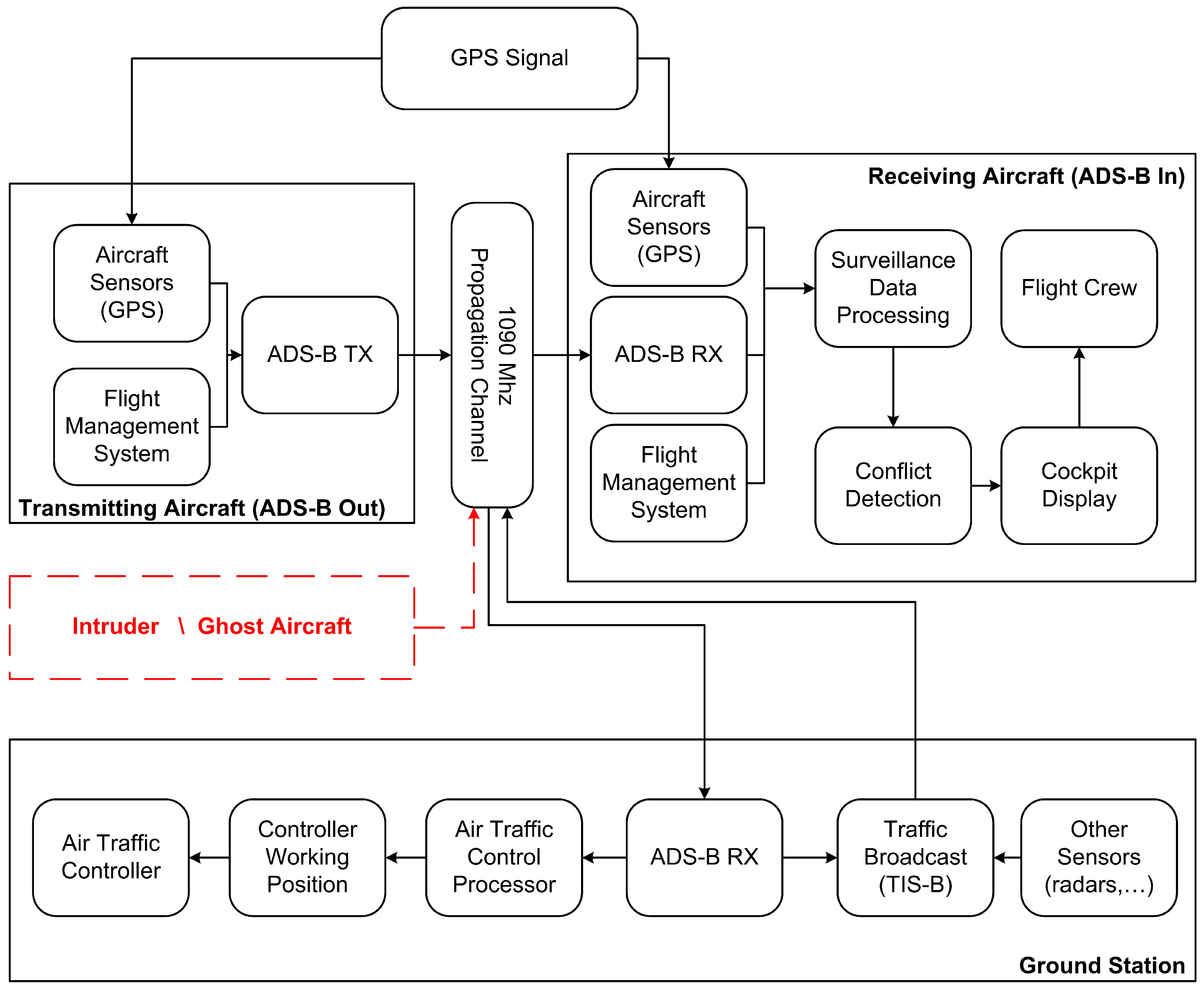
Figure 2.
ADS-B/Mode S reply format.

Figure 3.
ADS-B pulse shape (on the left) and (on the right) a real example of ADS-B pulse (the two lines represent the IF signal and the relative envelope).
Figure 3.
ADS-B pulse shape (on the left) and (on the right) a real example of ADS-B pulse (the two lines represent the IF signal and the relative envelope).
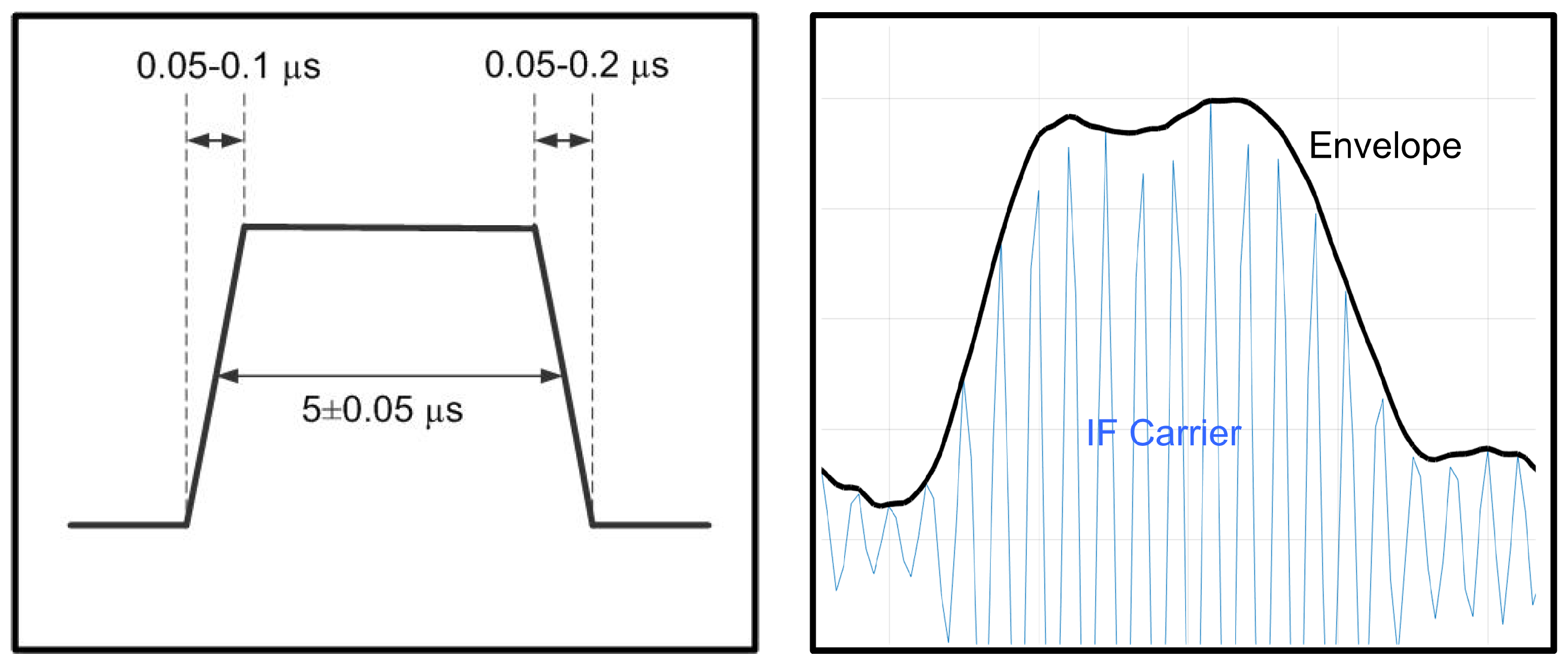
Figure 4.
Transponder Data Recorder (TDR) system pictures: on the left the TDR receiver, on the right the TDR antenna.
Figure 4.
Transponder Data Recorder (TDR) system pictures: on the left the TDR receiver, on the right the TDR antenna.
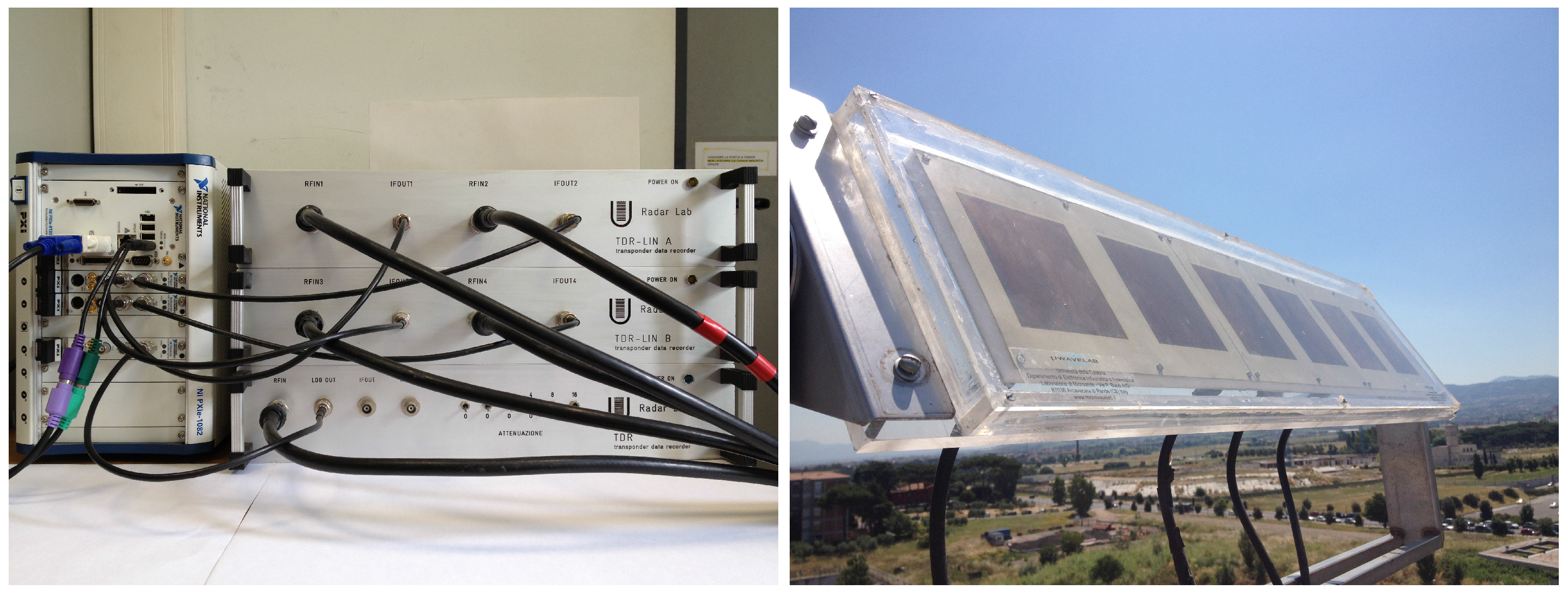
Figure 5.
Phase patterns examples of seven different aircraft: (a) Linear; (b) Quadratic; (c) Oscillating; (d) Non-Coherent; (e) Mixed: Quadratic+Linear; (f) Mixed: Linear + Linear and (g) Wave. All ICAO Addresses are anonymized.
Figure 5.
Phase patterns examples of seven different aircraft: (a) Linear; (b) Quadratic; (c) Oscillating; (d) Non-Coherent; (e) Mixed: Quadratic+Linear; (f) Mixed: Linear + Linear and (g) Wave. All ICAO Addresses are anonymized.

Figure 6.
Neural network block diagram.

Figure 7.
Confusion matrices of Neural Networks classification. (a) classification with 7 classes; (b) classification with 5 classes.
Figure 7.
Confusion matrices of Neural Networks classification. (a) classification with 7 classes; (b) classification with 5 classes.


Table 1.
Classification results for 17 November 2016.
| Classification Results for 17 November 2016 | ||
| Total number of replies | 232,888 | |
| Classified replies | 151,226 (64%) | |
| Total number of Aircraft | 291 | |
| Classifed Aircraft | 202 (69%) | |
| Assigned Class for 17 November 2016 | ||
| Class | n. of Aircraft | % of Aircraft |
| 1—Linear | 40 | 19.8 |
| 2—Quadratic | 27 | 13.4 |
| 3—Oscillating | 14 | 6.9 |
| 4—Non Coherent | 109 | 53.9 |
| 5—Mixed: Quadratic + Linear | 8 | 4.0 |
| 6—Mixed: Linear + Linear | 1 | 0.5 |
| 7—Wave | 3 | 1.5 |
Table 2.
Classification statistics, probability of false alarm and probability of detection for different types of attack and different values of ().
Table 2.
Classification statistics, probability of false alarm and probability of detection for different types of attack and different values of ().
| NN Type | 7 Classes NN | 5 Classes NN | ||
|---|---|---|---|---|
| Logic () | (4/10) | (6/10) | (4/10) | (6/10) |
| Total number of Aircraft | 676 | 676 | 676 | 676 |
| Classifed Aircraft | 291 (43.0%) | 302 (44.7%) | 304 (45.0%) | 318 (47.1%) |
| Not Classified Aircraft | 261 (38.6%) | 261 (38.6%) | 248 (36.6%) | 248 (36.6%) |
| Aircraft sent to the Operator | 124 (18.4%) | 113 (16.7%) | 124 (18.4%) | 110 (16.3%) |
| 3.6 % | 3.6 % | 3.8 % | 3.7 % | |
| (No Aircraft—SDR) | 100% | 100% | 73.8 % | 73.8 % |
| (No Aircraft—Transponder) | 70.9% | 66.4% | 68.9 % | 63.8 % |
| (Aircraft—SDR) | 100% | 19.3% | 75.6 % | 12.6 % |
| (Aircraft—Transponder) | 64.4% | 12.7% | 61.5 % | 10.6 % |
© 2017 by the authors. Licensee MDPI, Basel, Switzerland. This article is an open access article distributed under the terms and conditions of the Creative Commons Attribution (CC BY) license (http://creativecommons.org/licenses/by/4.0/).
Share and Cite
MDPI and ACS Style
Leonardi, M.; Di Gregorio, L.; Di Fausto, D. Air Traffic Security: Aircraft Classification Using ADS-B Message’s Phase-Pattern. Aerospace 2017, 4, 51. https://doi.org/10.3390/aerospace4040051
AMA Style
Leonardi M, Di Gregorio L, Di Fausto D. Air Traffic Security: Aircraft Classification Using ADS-B Message’s Phase-Pattern. Aerospace. 2017; 4(4):51. https://doi.org/10.3390/aerospace4040051
Chicago/Turabian StyleLeonardi, Mauro, Luca Di Gregorio, and Davide Di Fausto. 2017. "Air Traffic Security: Aircraft Classification Using ADS-B Message’s Phase-Pattern" Aerospace 4, no. 4: 51. https://doi.org/10.3390/aerospace4040051
Note that from the first issue of 2016, this journal uses article numbers instead of page numbers. See further details here.