High Fidelity Multi-Objective Design Optimization of a Downscaled Cusped Field Thruster


1
School of Engineering, RMIT University, Melbourne, Victoria 3001, Australia
2
Aerospace Systems Pty Ltd., Prahran, Victoria 3181, Australia
*
Author to whom correspondence should be addressed.
†
These authors contributed equally to this work.
Aerospace 2017, 4(4), 55; https://doi.org/10.3390/aerospace4040055
Submission received: 27 September 2017
/
Revised: 1 November 2017
/
Accepted: 11 November 2017
/
Published: 18 November 2017
(This article belongs to the Special Issue Micro-Propulsion Systems and Components for Small Spacecraft—Current Trends, Innovations and Challenges)
Abstract
:The Cusped Field Thruster (CFT) concept has demonstrated significantly improved performance over the Hall Effect Thruster and the Gridded Ion Thruster; however, little is understood about the complexities of the interactions and interdependencies of the geometrical, magnetic and ion beam properties of the thruster. This study applies an advanced design methodology combining a modified power distribution calculation and evolutionary algorithms assisted by surrogate modeling to a multi-objective design optimization for the performance optimization and characterization of the CFT. Optimization is performed for maximization of performance defined by five design parameters (i.e., anode voltage, anode current, mass flow rate, and magnet radii), simultaneously aiming to maximize three objectives; that is, thrust, efficiency and specific impulse. Statistical methods based on global sensitivity analysis are employed to assess the optimization results in conjunction with surrogate models to identify key design factors with respect to the three design objectives and additional performance measures. The research indicates that the anode current and the Outer Magnet Radius have the greatest effect on the performance parameters. An optimal value for the anode current is determined, and a trend towards maximizing anode potential and mass flow rate is observed.
1. Introduction
The implementation of electric propulsion (EP) thrusters on spacecraft is largely driven by weight reductions over traditional chemical propulsion thrusters. EP has a distinct payload reduction advantage over chemical propulsion and offers increased operational life, in excess of 10,000 h, and high specific impulse Isp, of 1500–4000 s, but relatively low thrust values of around 30–230 mN [1], which is useful for long range missions and small attitude adjustments for satellites [2]. EP offers improved specific impulse and operational lifetimes over chemical thrusters with a significant reduction in the amount of propellant required. The reduction in propellant due to reduced fuel consumption and low system mass leads to a significant reduction in launch costs, making this technology desirable. Keller et al. [3] has identified several upcoming satellite missions that require smaller EP thrusters for increased precision attitude and control.
The gridded ion thruster (GIT) and the Hall effect thruster (HET) are high efficiency flight tested examples of EP. Both of these propulsion concepts are well understood and have values of Isp ranges from 1500 to 6000 s [4]. Both of these designs provide great performance but also come with drawbacks such as system complexity and thruster erosion from impinging ions on grids or channel walls [5], which limits their operational lifetimes. First developed by Thales Electron Devices in 1999 as the Highly Efficient Multi-stage Plasma Thruster (HEMP-T) [3], based on travelling wave tube technology, the Cusped Field Thruster (CFT) concept has a simplified design and demonstrates improved performance characteristics over GIT and HET, with Isp in the range of 2000–3000 s, and an estimated minimum operational lifetime of over 16,000 h [6]. Since the first HEMP-T patent by Thales Electron Devices (TED) in 1999, similar thruster designs have been developed and tested by different institutions around the world; MIT’s Diverging Cusped-Field Thruster (DCFT) [7], Stanford’s DCFT [8] and the Harbin Institute of Technology’s CFT [9].
The CFT shares the HET axial electric field and radial magnetic field, using the Hall Current to ionize the propellant. The CFT uses Permanent Periodic Magnets (PPM) in series, aligned axially along the chamber with reversing polarity to contain the plasma through the magnetic mirror effect, and avoids plasma contact with the chamber walls that typically results in wall erosion. Wall erosion is one of the main impediments on HET and GIT operational lifetimes and experimental testing on CFT designs has shown no erosion [5]. The arrangement of the PPM reduces charge losses by restricting the radial motion of the plasma, resulting in high ion beam efficiencies similar to GIT, in the region of 80–90%, compared to 60–70% for HET [5]. Between the magnetic stages of the PPM, a cusp region forms where the magnetic field runs radially from the chamber wall, repelling the plasma [5]. This impedes the electrons from moving upstream by the magnetic mirror effect. The magnetic field strength is optimized to concentrate the ion beam discharge to the center of the engine. The cusp regions effectively divide the engine in to separate magnetic cell stages.
The magnetic field strength B is chosen such that the Larmor radius of the electrons is much smaller than the inner geometry of the discharge chamber. This effectively confines the electrons to the center of the engine that in turn helps to electrostatically confine the ions, of which the magnetic field has little effect upon as the mean free path of the ion is significantly smaller than its gyro radius and is not considered magnetized [10]. Ions that escape this confinement contribute to an overall positive charge of the chamber wall and therefore an enhancement of ion beam formation [11]. The CFT has the ionization and acceleration zone separation characterized by the GIT. The thruster also features a steep potential drop occurring immediately after the exit cusp whilst the plasma potential is maintained at a relatively constant level throughout the engine [5,11,12,13]. This is mainly due to the magnetic cusp at the thruster exit. The electrons emitted from the cathode are trapped here and form the cloud. The neutralizer, while not necessary for performance, also prevents the discharge from interfering with other spacecraft systems. The confined electron cloud acts as a virtual acceleration grid, like the GIT, resulting in high efficiencies and ions close to the potential of the anode.
Focusing on the need for micro thrust propulsion solutions for high precision station keeping of satellites, a parametric study to downscale the original HEMP-T concept was conducted by Keller et al. [3]. Reducing the size of the CFT could result in better performance over current EP thrusters, with reduced weight, reduced fuel consumption and therefore more launch cost savings for satellites applications. Keller et al. [3] conducted a performance parameterization study of the HEMP-T design. In their efforts to scale down the size of the thruster into the micro-newton thrust range, they have shown the relation of several inter-related sizing parameters. Testing various thruster configurations and the sensitivity of parameters (chamber diameter, magnetic ring outer diameter, the distance between magnetic stages and the number of stages) to four output performance measures (mass flow, anode current, plume divergence, acceleration efficiency), an approximate range of values for the micro-newton thrust level was obtained. These specifications provide some insight into the sizing sensitivity of the design and deliver key indicators in the way of thruster sizing ratios such as increasing magnetic field intensity for decreasing discharge chamber diameters to reduce losses. However, the performance remained considerably low in comparison, with the larger scale counterparts with a maximum Isp achieved of 2000 s, whereas the higher end of the performance ranged upwards of 3000 s [6]. These results reflect the geometric scaling challenges as explored with closed drift thrusters [14].
A state-of-the-art methodology to investigate such higher end performance ranges has been developed by coupling an analytical global-variable based steady-state power and plasma model solver and a multi-objective design optimization (MDO) capability based on evolutionary algorithms. This approach enables robust and effective population-based optimization, assisted by surrogate modeling, which can reduce the computational cost by approximating the model calculation in lieu of expensive true computational evaluation. The coupled simulation/MDO approach builds on the preceding work by Muffatti and Ogawa [15] through the utilization of a higher fidelity simulation for more accurate results. This paper presents the outcomes of a multi-objective design optimization of a small-scale CFT analysis that has been conducted for three major objectives commonly targeted in spacecraft propulsion; that is, (1) thrust T, (2) efficiency ηt, and (3) specific impulse Isp. The magnetic topology is examined for representative high-performance configurations to investigate the underlying thruster physics. The surrogate models are trained with the archive of solutions evaluated during the optimization. They are used to perform variance-based global sensitivity analysis to identify the key design factors as well as an additional large-scale optimization solely employing the surrogate prediction to better capture the effects of the design parameters on the CFT’s performance.
2. Materials and Methods
The key indicators of thruster performance, thrust T, total efficiency ηt, and specific impulse Isp, are used to determine the performance of the downscaled CFT in comparison to similar propulsion devices. Starting with the basic relations of spacecraft propulsion thrust T equating with force on a charged particle in an electric field, specific impulse Isp and power Pa [2,10,16].
where E is the magnitude of the electric field, Φa and Ia are the anode voltage and current, respectively, and m is the mass flow rate of propellant (anode and cathode). The total efficiency is defined by the ratio of jet power to anode power Pa. However, for HET, anode efficiency is generally utilized, defined as:
Expansion on the component efficiencies introduces more measurable voltage ηv, beam ηb, and utilization efficiencies ηu [17]. Voltage efficiency refers to how efficiently the ions are accelerated by the anode potential; the beam efficiency relates the anode current to the beam current and the utilization efficiency refers to how much propellant is ionized to create the ion beam.
From Goebel and Katz [2], the beam current can be determined through the mass flow rate.
where the subscript b indicates the ion beam, Q is the averaged ionic charge, Ib is the total ion current in the beam, cos2θ accounts for plume divergence where ions are not accelerated parallel to the engine axis, M is the mass of propellant atoms (2.18 × 10⁻²⁵ kg for Xe) and e is the elementary charge (1.602 × 10⁻¹⁹ C). The propellant is assumed to be Xenon, which is typical for CFT. Equation (6) is a basic equation that assumes 100% ionization and singly ionized for HETs, while it would not fully describe low ionization at low voltages and multiply charged ions at high voltages, which could occur in practical applications.
A key feature of the CFT concept is the high voltage operational ranges, typically between 500 and 2000 V. Keller et al. [3] found anode voltages below 500 V resulted in lower efficiencies at the same mass flow rates, which was supported by the results of Ma et al. [9]. Thus, the effects of low ionization were not captured by this study. The experimental study and theoretical characterization of thrust in Keller, et al. [3] assume that the ion current can be approximated by the anode current with a less than 20% error and that the particles are singly ionized totally. Matlock [17] measures the ion beam current for the DCFT through electrostatic probing. The mass utilization efficiency, described in part in Equation (7), is sensitive to the beam current and mass flow. As a result, this study assumes that the ion beam current can be sufficiently approximated by Equation (6), with the consideration of presence of up to 20% doubly charged ions in the mass utilization efficiency for the MDO process. This is detailed in Goebel and Katz [2], where the mass utilization efficiency correction factor is given by αm, which consequently resulted in the effects of multiple ion species largely not being captured in this study with αm = 0.9.
Applying this methodology without the correction factor to the Variable Magnet Length Cusped Field Thruster (VML-CFT) validation case of Ma et al. [9], resulted in a mass utilization efficiency of 89%, which correlates well to the results of Matlock [17] in a comparable study on the DCFT, where the mass utilization efficiency was experimentally measured to be 87%.
The plume divergence efficiency is not taken into account in the present model. Experimental testing would be required to accurately determine the divergence angle. A divergence angle of θg = 60° can be assumed based on Keller et al. [3], and this is supported by the measured divergence angle of 56° of the DCFT by Matlock [17]. The divergence efficiency can be defined by Löb and Freisinger [18] by
The assumptions made regarding the acceleration, divergence and utilization efficiencies will be applied in post processing of the MDO results, as these are factors which this study is unable to accurately define with the present methodology and will have a uniform effect on the objective parameters.
Kornfeld et al. [5] describe a simplified power balance description of the HEMP-T based on the plasma fluid theory. A one-dimensional set of equations (28 in total) to be solved simultaneously can be used to obtain a reasonable estimate of the thruster performance. As the only known values in the equation set are the probabilities to reach the channel wall at the cusp locations and these probabilities are based on the magnetic field strength, the thruster performance can be estimated through only a few parameters. These are anode potential, anode current and the ratio of magnetic field strength from the axially aligned region to where the fields radially cross the discharge channel walls, i.e., the magnetic mirror strength. It is also important to note that the ratios (described in Kornfeld et al. [5]) of power transferred to excitation, ionization and thermalization are only estimations. It is also stated that inclusion of angular and ionization efficiencies could allow for predictions of total thruster efficiency. The following description was derived from the equation system presented by Kornfeld et al. [5], where a full description of the power model can be found.
The operational principle of the CFT is based on the magnetic mirror effect due to the Permanent Periodic Magnets (PPM), which reduces losses from electrons impinging on the discharge chamber walls. This is because the particle is acted on by the Lorentz force, where the magnetic field does not have an impact on the particle, rather an axial force relative to the magnetic field acts on the particle in the opposite direction defined by the Lorentz force in a cylindrical field [2,13,15,19].
When the particle is moving through a magnetic field of increasing strength, the magnetic moment is constant, which means that the magnetic moment at the high field and at the low field can be balanced by equating the magnetic moment of two points, where the subscript 0 indicates the low field and m the high field.
Through the conservation of the particle kinetic energy, the velocity of the particle is defined by parallel and perpendicular velocity components.
The magnetic mirror effect is not entirely efficient, with the direction of the velocity vector needing to be within an acceptance angle in order to escape the mirror effect. This is established between the difference of the high and low magnetic field strength regions, as derived below [19]:
This is then used to calculate the cusp arrival probabilities of the electrons, which is used as the basis for thruster performance using the one dimensional power equations [5]:
The cusp arrival probabilities are directly related to the accuracy of the simulated magnetic topologies of the thruster, which is calculated by means of two-dimensional electromagnetic field analysis.
Shown in Figure 1 is the process chain followed to produce decision variables and delivery of the objective functions. The decision variables are assessed to assure the geometry is physically possible before they are passed onto the software ANSYS Maxwell [20] for model construction and the computation of the magnetic field. Magnetostatic analysis is then performed to calculate the magnetic field strength topologies (Figure 2), and then an electrostatic analysis is performed to determine the potential at the thruster exit and in the plume.
The data is extracted from the magnetic topology to compute the cusp arrival probability for each location throughout the thruster. These conditions are subsequently passed to be used in the power balance calculation. The resultant solutions from this are post-processed to deliver the objectives and assess if they lie within the set of physical constraints. They are then submitted to the MDO algorithms for evaluation. This cycle repeats as more designs are produced and evaluated as per the set criteria.
Design optimization is performed by employing evolutionary algorithms [21,22]. In particular, use is made of the elitist non-dominated sorting genetic algorithm [23] assisted by surrogate modelling. It is a population-based approach where the candidate solutions in the population pool evolve over generations. A population size of N = 64 is used in this study to be evolved over 40 generations for the initial MDO study employing simulation, and that of N = 100 over 100 generations in the MDO run performed solely based on prediction from surrogate models. These values have been chosen to sufficiently explore the design space for a three-objective design problem with five decision variables within reasonable computational effort. Recombination operators are applied to the previous generation’s decision variable values to create offspring. A simulated binary crossover and polynomial mutation are used as recombination operators at a given probability (1.0 and 0.1, respectively, in this study) with a specified distribution index (10 and 20, respectively) [22]. The use of a strongly elitist non-dominated sorting genetic algorithm always retains the best solutions across generations. This means that there is no incentive for parents to survive but to use the crossover mutation to broaden the search for better solutions; hence the crossover probability is given by 1.0. Surrogate modelling [24] is commissioned to estimate the possible values of the objectives and constraints in an inexpensive manner, imitating the behaviour of the solutions from the magnetic and power analyses with meta-models characterized by appropriate mathematical functions based on the magnetostatic, electrostatic and power balance simulations. Different surrogate models are employed to best predict the thruster performance with a minimum error threshold satisfied, as discussed below. The surrogates are constructed by using a fraction (90% in this study) of the actual solutions calculated from the magnetic and power distribution models to prevent over fitting, whereas the remainder (10%) of the evaluated solutions are used to assess the performance of the surrogate models [22]. Surrogates for each of the objective and constraint functions are trained by using a subset of the archive, which is created by selecting the solutions closest to the centroids of the k clusters obtained through k-means clustering [25]. Multiple surrogate models are considered and evaluated: quadratic response surface model, [26] artificial neural network (ANN) models including the radial basis function network [27] and multilayer perceptron model, [28] which are single-layer and feed forward types of ANN models, respectively, and Kriging model based on Gaussian process regression [29]. The mean squared error (MSE) in the actual and predicted values of the objectives and constraints is calculated for the remaining (10%) solutions and used as the measure to validate the surrogate models. Prediction from the best surrogate model with a minimum error is adopted to replace simulation analysis, only if the MSE is within a threshold value of 5% for all objective and constraint functions, which has been set to effectively allow reasonable investigation by striking a balance between prediction accuracy and computational cost, and the distance to the closest point in the archive is smaller than 5% [22]. The advantage of the MDO approach undertaken in the present study is the ability to maintain multiple objectives and perform optimization to aim at all the objectives simultaneously, which is the primary virtue of MDO. This removes the no need for weighting on the objectives to convert a multiple-objective optimization problem to a single objective one, as required for a single-objective optimization framework.
The three objective functions used to evaluate design performance are thrust T, efficiency ηt and specific impulse Isp (the efficiency term with the subscript t is somewhat of a misnomer here, usually descriptive of total efficiency, and it must be stated that the model presented in this paper does not take into consideration plume divergence losses or an accurate representation of acceleration efficiencies). The ηt term is comprised of the measures of efficiencies within the thruster model, that is, the beam efficiency ηb, the mass utilization efficiency ηu and the voltage efficiency ηv. The decision variables and their input ranges are chosen to represent the main design factors investigated in this study (shown in Algorithm 1) are Φa (V), Ia (A), mf (sccm), Inner Magnetic Radius (IMR) (mm), and Outer Magnetic Radius (OMR) (mm). The optimization statement can be expressed as follows (the negative sign for the objective functions denotes a maximization problem). The decision parameters Φa (V), Ia (A), and mf (sccm) relate to the objective functions through Equations (1)–(5) and the initial conditions of the CFT at the anode. The magnetic radii, IMR and OMR, are related to the objective functions through the one-dimensional simplified power balance model. The radii effect the strength of the magnetic field in the high and low regions which is used to solve the power balance model, describing the plasma potentials, cusp potentials, ionization source currents, and electron and ion currents across plasma cells that divide the discharge chamber length in the simplified model. From this determination, the beam and grid efficiencies is made, calculating power losses at the anode, cusps and due to ionization and excitations, which impacts on each separate objective function.
| Algorithm 1 Optimization parameters | |
| Maximize: | T, ηt, Isp |
| Subject to: | 0 ≤ Φa (V) ≤ 1000 |
| 0 ≤ Ia (A) ≤ 10 | |
| 0.2 ≤ ma (sccm) ≤ 50 | |
| 2 ≤ IMR (mm) ≤ 50 | |
| 2 ≤ OMR (mm) ≤ 50 | |
To validate this approach, a model of the experimental setup of the CFT thrusters from the available literature are created using ANSYS Maxwell. The selected experimental model to validate the procedure is the VML-CFT from Ma et al. [9]. This model is considered because of its detailed account of the physical dimensions and material properties of the thruster and its subsequent analysis of the results gives a robust range of observation points that can be modeled and compared.
From the simulated model, two analyses are performed; firstly, a magnetostatic solver is used to determine the magnetic field strength at the cusps along the inner engine radius/wall. This magnetic strength is compared to the magnetic strength at the centerline of the engine, where the particles are in the observed loss cone [17,19]. The difference between the magnetic field strengths is used to determine the Magnetic Mirror Ratio at each cusp. This is then used to calculate the cusp arrival probabilities at each magnetic cusp. The cusps arrival probabilities for the validation model at the four magnetic cusps are shown in Table 1.
The calculated cusp probabilities accuracy is difficult to determine through a lack of available reference data. From the literature, it is expected that the cusp probabilities will differ significantly from the experimental probing of the thrusters. From the data of Kornfeld, et al. [5], from which the simplified HEMP-T model originates, the cusp probabilities observed in thruster Demonstration Model (DM) 9.2 and DM 10 appear to correlate well with the exception C2 and C4 which is expected to be significantly larger then measured. The cusp arrival probabilities are expected to be below 5% of electrons with a noted maximum at the third cusp. While this is reflected in the simulations, the validation of the cusp arrival probabilities is significantly underpinned by the overall accuracy of the simplified HEMP-T model by Kornfeld, et al. [5], and in comparison to experimental research (as documented in Table 2) as well as in comparison to the preceding results by Muffatti and Ogawa [15], especially in relation to efficiency.
The second analysis performed is an electrostatic simulation, which is used to calculate the potential drop in the plume. Using the electrostatic analysis results, the difference between the cusp potentials at the plume cell and the thruster exit can be more accurately predicted in line with observations made in the literature. The simplified HEMP-T model Kornfeld et al. [5] tended to over predict the potential in the plume region, which gave rise to efficiency inaccuracies when calculating the grid efficiency and acceleration efficiency as well as over predicting the beam current, Ib. The results of the electrostatic thruster solution are shown in Table 3. It shows the discrepancies between the HEMP-T simplified model assumptions and the observed potential behavior demonstrated in the simulation.
The expected outcomes of the internal magnetic cell potentials should be in line with the voltage applied to the anode, 500 V for the VML-CFT, in accordance with Kornfeld et al. [5]. The variation is likely due to electrostatic model setup and the over prediction of the initial conditions using the nonlinear least squares method.
The comparison between the results of Ma, et al. [9] for a VML thruster with magnetic cell length ratios of 2:9:0.5 is shown in Table 2. This specific experimental model represented the peak performance characteristics of the thruster. The comparison of the results is very close to the experimental result. Except for the lowest mass flow rate where the total efficiency has an approximate 10% error, the efficiencies are only slightly higher than the measured result with a trend toward convergence with higher propellant mass flow rates. The thrust is measured from two different methods, from Kornfeld et al. [5] and then from the method described by Keller et al. [3]. These calculations are both good predictions of the thrust and appear to validate the approach undertaken. With very close predictions for propellant mass flow rates between 20 and 40 sccm, it would be appropriate to restrict the considered design MDO process between these limits. The model was a poor predictor of specific impulse. This appears to be owing to the sensitivity of the Isp calculation to the small thrust inaccuracy and as a result the Isp does not see the desired variation with mass flow rate.
Variance-based global sensitivity analysis is performed to investigate the influence of each decision variable xi as input (i.e., design parameter) on the objective function y as output (i.e., thruster performance parameter). A numerical procedure (Sobol’s variance decomposition [30]) is employed to derive the sensitivity indices, facilitated by surrogate modelling [24]. Input matrices X of a base sample quantity of 10,000 and multiple columns for the decision variables are built by using quasi-random numbers [30] within the range for each variable. Output vectors Y are obtained by forwarding the input matrices to the surrogate model that is of the greatest prediction accuracy. The first-order indices Si and total-effect indices STi are calculated by the method outlined in Reference [31], defined as:
The CFT model developed in ANSYS Maxwell is designed to be as simple as possible for use in the MDO calculations. This is due to the computationally expensive nature of this process and to facilitate the identification of the relationships between the output objectives and the decision variables. The model is set up for two-dimensional Maxwell simulation, and the CFT is modeled by assuming axis symmetry at the engine axis. The mesh is created with 9000 elements. The thruster itself features a consistently straight chamber, three magnet stages with spacers (doubling as field guides), and the thruster housing. Used in the simulation are Samarium-Cobalt (SmCo) 27 megaguass-oersteds (MGOe) magnets stacked with reversing polarity and the thruster housing material used is Al 6061-T6. The spacers are made from pure iron due to the high conductivity of the material as well as to improve commonality with other HEMP-T/CFT designs [3,8,11,16]. Several geometric constraints were implemented to restrict the scope and output of the design space, including that imposed on the inner and outer radii, i.e., IMR and OMR. The basic physical constraints implemented into the model are simple in nature, that is, rejection of geometries that overlap in regions as infeasible solutions in MDO. The somewhat arbitrary limitations selected are those for the inner thruster channel geometry (2 mm radius) as a lower limit and the upper limit (50 mm radius) to remain approximately within the limits of the standard CubeSat form. Further restrictions are placed on the utilization of propellant regarding anode current. The upper limit is set in the pre-processing stage where Ib is replaced with Ia and cannot produce a value exceeding 1, because the only ion species under consideration are the singly charged variety [2].
3. Results
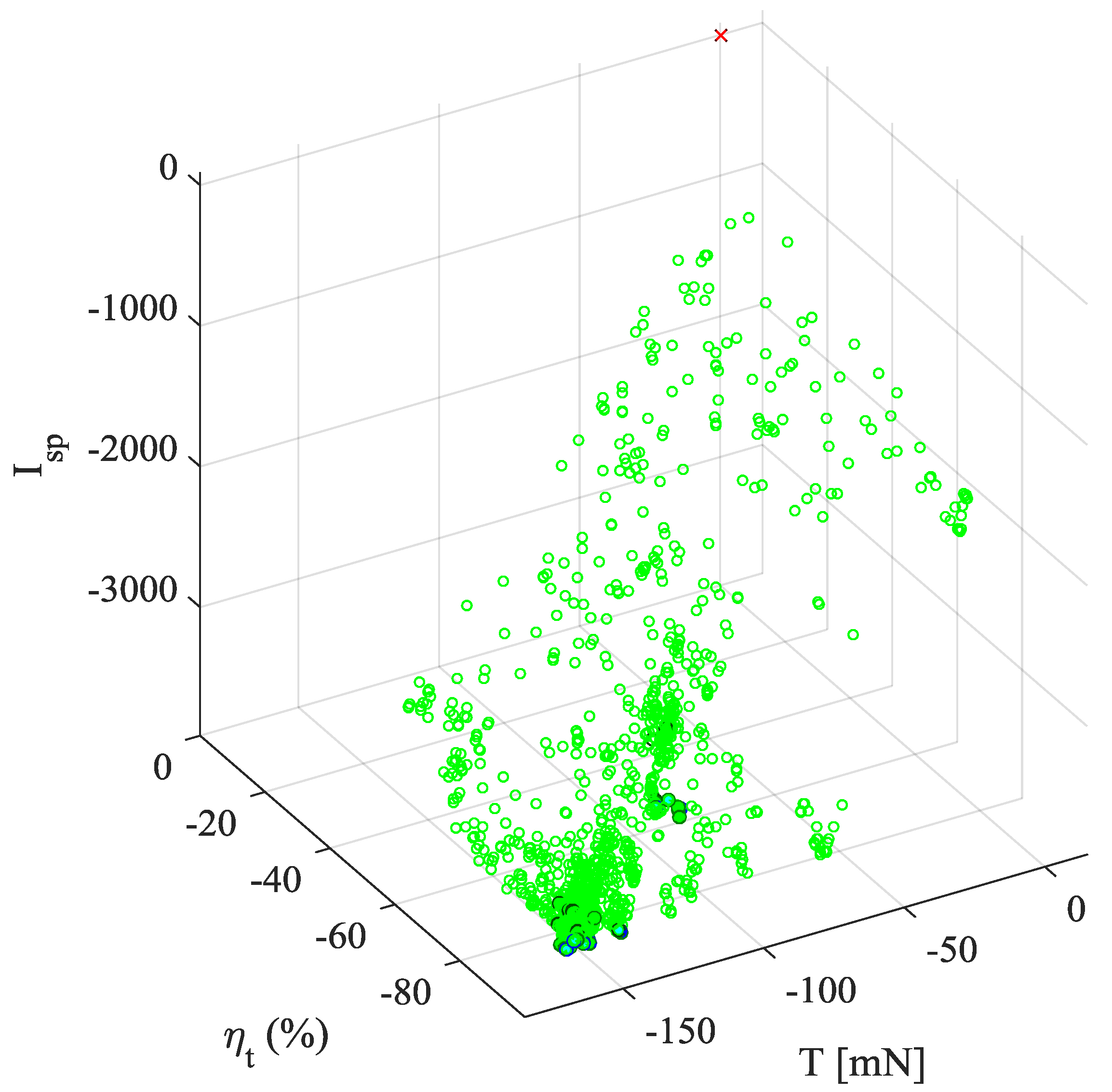
Multi-objective optimization based on evolutionary algorithms is performed for up to 40 generations with a population size N of 64. Surrogate models were constructed after 40 generations to be employed in a surrogate-only optimization with a population size of N = 100 evolved over 100 generations. It has been performed to fully explore the design space at reduced computational cost by substituting simulations with surrogate prediction entirely. The surrogate prediction errors are 0.8% for T, 1.6% for ηt, and 1.2% for Isp. Figure 3 displays the non-dominated individuals obtained thus, where a vector of the objective functions f(x’) is said to be non-dominated if there exists no other vector f(x) that satisfies f(x) ≤ f(x’) with fi(x) < fi(x’) for at least one index i ∈ (1, 2, 3) [32]. Also, included in these plots are 4 individuals (S1–4) that have been selected to investigate the key design factors and associated context of their creation. S1, S2, and S3 are non-dominated solutions that perform the best with respect to each design criterion, that is, S1 in T, S2 in ηt, and S3 in Isp. S4 is a suboptimal solution, characterized by low performance in all 3 objective categories.
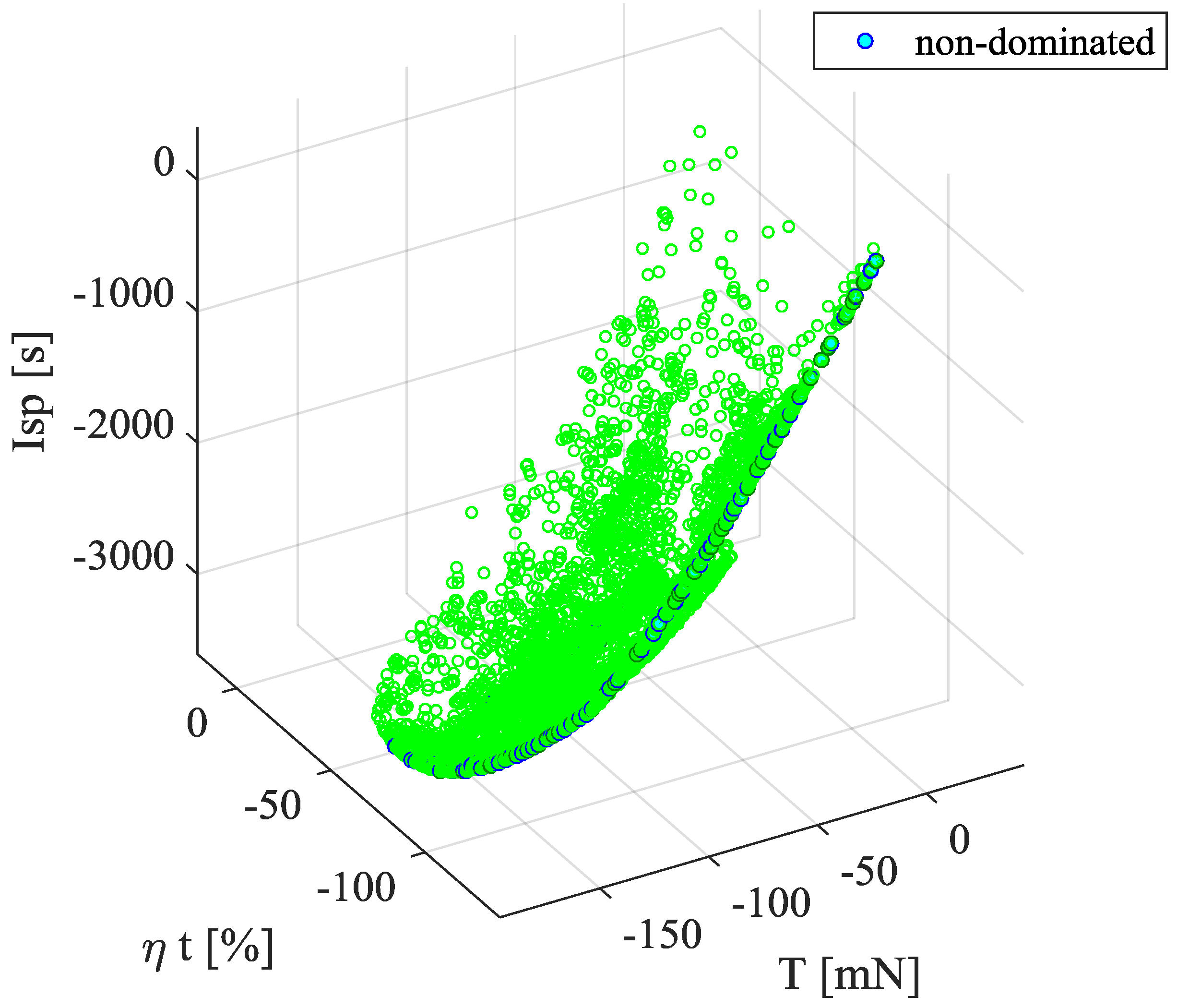
The feasible solutions from the MDO coupling ANSYS Maxwell analysis are presented in Figure 3. These results are used to build surrogate models. Figure 4 displays the solutions from an MDO study performed by solely relying on surrogate prediction. It shows a uniform distribution of solutions along the Pareto optimal front. The smoothness of the Pareto optimal front indicates the robust nature of the surrogate modeling optimization using a population size of 100 evolved over 100 generations. It means that the solution converges to a globally optimum point and the process is unlikely to have excluded feasible non-dominated results. The quality of the optimization is a complex concept but can be assessed by the metrics of performance defined by Zitzler et al. [33]. Figure 4 demonstrates reasonable performance of the MDO based on the distance between the non-dominated solutions and the Pareto optimal front, a uniform distribution of feasible solutions, and a wide range of solutions are explored for each objective [33].
Sensitivity Analysis
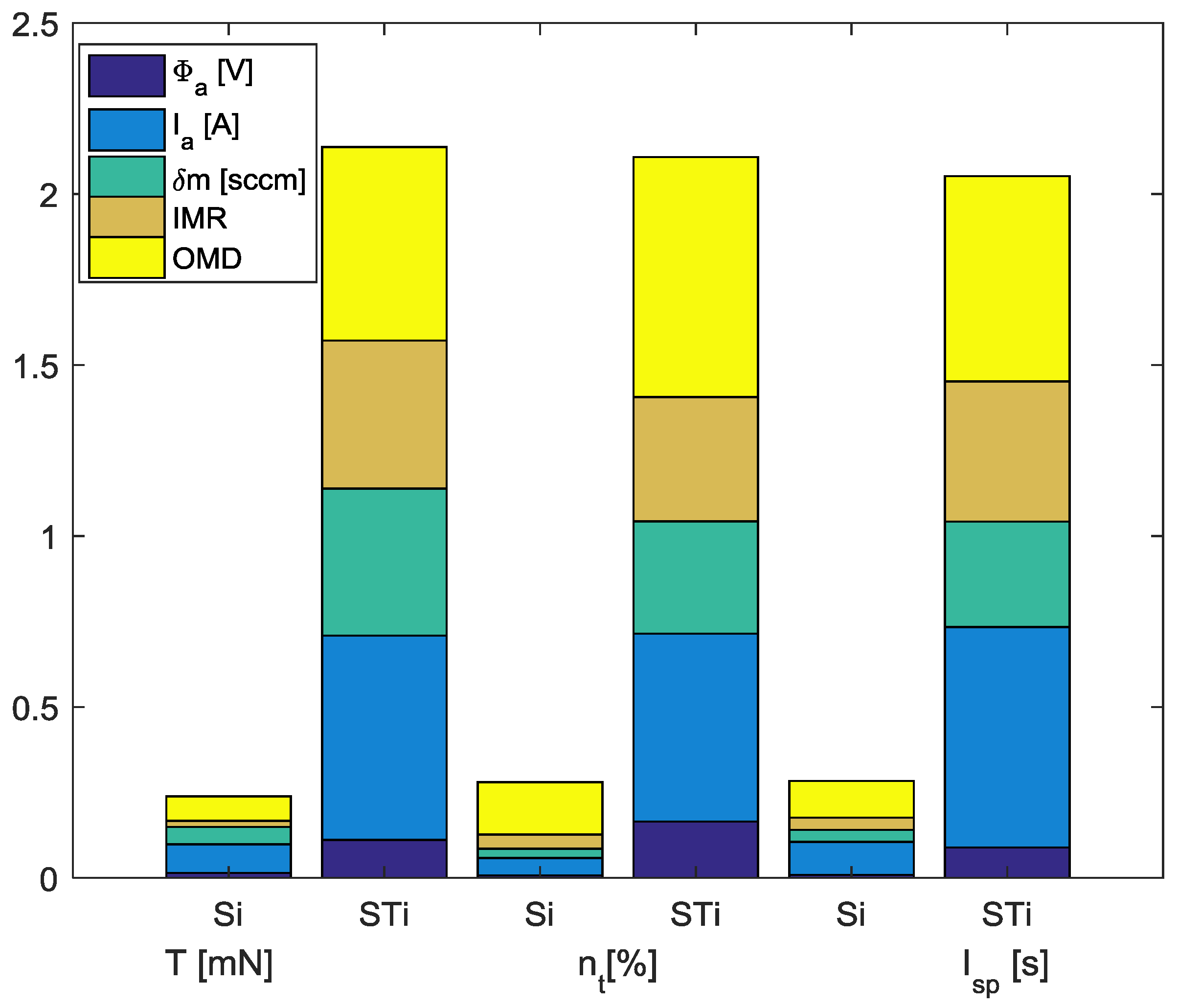
Figure 5 displays the first-order sensitivity indices Si and the total-effect indices STi. They indicate the main and overall effects of the input parameters (decision variables) respectively, i.e., Φa, Ia, ma, IMR, and OMR on the output parameters (i.e., objective functions), namely thrust T, efficiency ηt, and specific impulse Isp. The difference between the total-effect index STi and the first-order index Si is indicative of the degree of the influence of the decision variable in combination with other decision variables (i.e., interactions) on the objective functions [30]. If the decision variables are characterized by the sum of both first-order and total-effect indices being near unity (i.e., Σ Si ≈ 1 and Σ STi ≈ 1), this indicates that the effects of individual decision variables are linearly additive. From Figure 5 it is observed that most of the influence on the design is based on 4 critical design parameters; OMR, IMR, Ia, and ma. Ia has the most influence on thrust T and specific impulse Isp, while OMR is dominant in total efficiency. From Figure 5, it is evident that the decision variables exhibit similar influence across the three objectives as to be expected from Equation (4).
The first-order indices are shown in Table 4, demonstrating the large influence of IMR, OMR, Ia, and ma across the objective functions with the anode potential exerting significantly lower influence over the output parameters. The summation of the first-order effects on thrust is 0.2386 while that of the total-effect indices on thrust (Table 5) is 2.137, indicative of the highly nonlinear relationship between the input and output parameters. The total-effect indices tabulated in Table 5 indicate that the indices follow the same order of influence but with all variables increasing significantly in magnitude due to the involvement of other design parameters.
The large influence that ma and Ia have on ηt is not entirely unexpected due to the highly interrelated nature of total efficiency calculation. The anode current is strongly dependent on the mass flow rate, i.e., higher mass flow results in higher thrust as per Equation (1), but considering these decision variables independently would allow to assess the degree of their influence on the objectives and offer flexibility in identifying the optimal design. These results indicate the importance of matching these two parameters to achieve nominal conditions. However, it is important to note that other measures for the efficiency such as the acceleration efficiency and beam divergence losses are not taken into consideration in this model and would be required to be estimated from existing experimental research. The parameter influences on Isp continue this trend, subject to the considerable influence of the anode current, mass flow rate and OMR, which correlates to the results of Muffatti and Ogawa [15]. This is reinforced by the observations regarding thrust, where anode potential has little influence compared to the other decision variables. Given the interrelated nonlinear nature of the problem, the sensitivity analysis supports the use of the optimization process on the parameters to better understand the concept and underlying mechanism, and improve the thruster performance.
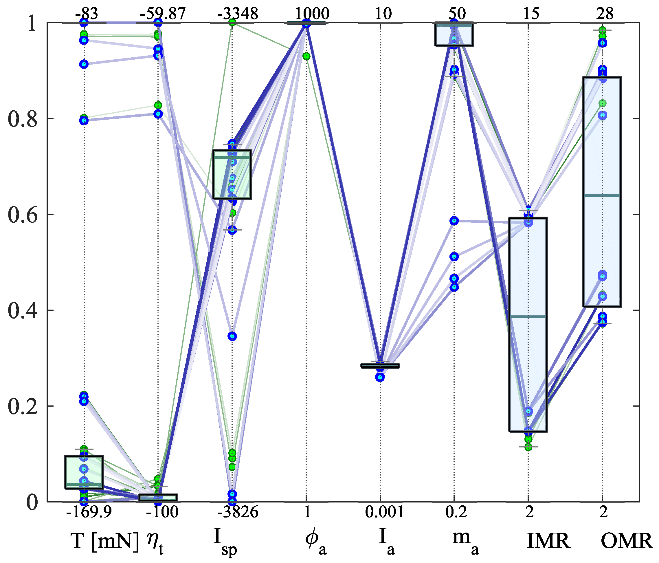
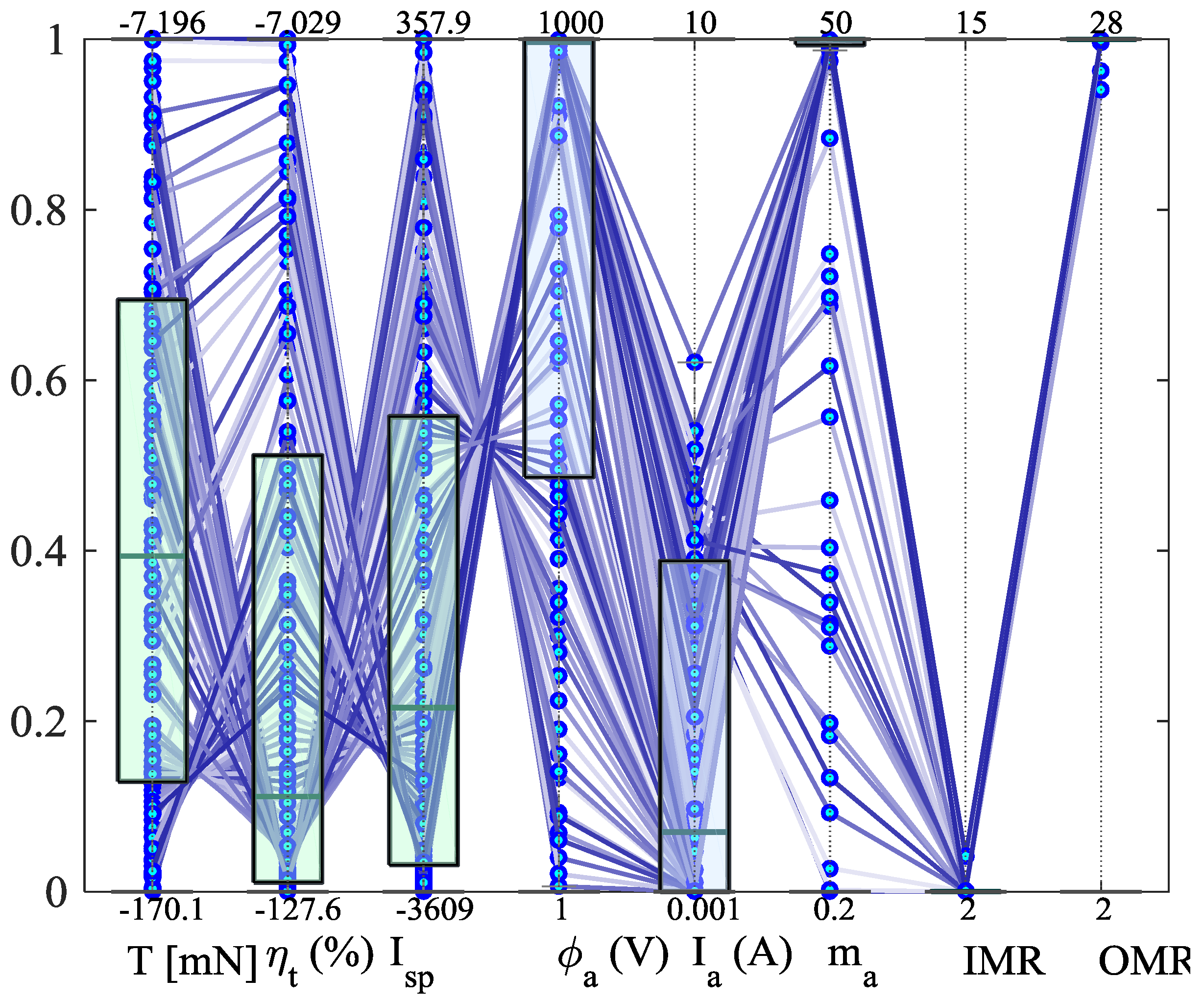
Figure 6 and Figure 7 are parallel coordinate plots drawn for the non-dominated solutions identified in the MDO study using analysis at the 40th generation and that with surrogate prediction at the 100th generation, respectively. They are utilized to identify the trends between the parameters. The plots are dependent on the order and scale of the variables where the pattern of the lines indicate a cooperating (parallel) or counteracting (crossing) trend between the parameters [34]. The parameters are arranged with the performance parameters first followed by the anode parameters because of the trends found in literature [3], which suggested the anode conditions have greater influence on the performance of the thruster. Further analysis is required to compare the decision parameters effect on each other. Figure 6 shows a positive, cooperating relationship between the thrust T, and efficiency ηt. However, there is a counteracting trend between efficiency ηt, and specific impulse Isp. In Figure 7, the relationship between specific impulse Isp, and anode potential Φa, is considered counteracting and negative. The trend of the subsequent design parameters, from anode potential Φa, to anode current Ia, is shown as cooperating and positive. A specific trend between anode current Ia, and mass flow ma, is not discernible. Counteracting negative trends are also observed between mass flow ma, and IMR as well as between IMR and OMR in Figure 6 and Figure 7.
The parallel coordinate plots also show that the variables are decisive, in that the variables must be more decisive if the lines gather, as occurs for IMR and OMR. For anode potential Φa, and mass flow ma, the performance could be further enhanced by expanding (loosening) the limits, as the upper limits have been reached for non-dominated solutions for these parameters.
Figure 3, Figure 5 and Figure 6 have been produced after the evolutionary process of the population consisting of 64 individuals over 40 generations. Displayed in Figure 3 are the non-dominated solutions from the MDO process, along with evaluated feasible design points. Of the non-dominated solutions, 3 solutions with the highest values for the objective parameters, thrust T, efficiency ηt, and specific impulse Isp, are selected from the 39 generated non-dominated solutions, along with single suboptimal design for comparison as shown in Table 6.
The first selected configuration S1 exhibits the largest thrust of all the designs. This design falls on the upper limit of both mass flow and anode potential decision variables. It also has the largest anode current of the non-dominated designs. The second selected point S2 has the highest measured efficiency of the evaluated feasible designs. It has the lowest specific impulse of its non-dominated peers, which while being similar in value to its peers, is quite significant due to the method of calculation, as observed during the validation process of this methodology. S2 has the most dissimilar physical configuration of the designs, with the IMR much closer to the engine axis and has the smallest thickness of the permanent periodic magnets. This indicates the role of IMR in achieving high thrust densities. In comparison to S1, S2 has comparable thrust, efficiency, anode potential, current and mass flow. The third selected point S3 has the highest specific impulse of all the evaluated designs. This is at the expense of thrust and efficiency. A reduction of about 90 mN of thrust is recorded and a reduction of about 40% efficiency is observed in comparison to its non-dominated peers. S3 has the lowest mass flow (over 50% reduction) and the lowest anode current and lower but comparable anode potential. The suboptimal design S4 operates at very similar conditions to S3. This is indicated in the results from the sensitivity analysis, where the impact of a reduced mass flow ma on the performance parameters is shown in Figure 5. It is also correlated by the spacecraft propulsion thrust equating to the force on a charged particle in an electric field, as per the conservation of energy.
The correction factors for mass utilization, acceleration and plume divergence efficiencies based on the experimental research of Keller et al. [3], Ma et al. [9] and Matlock [17] are shown in Table 7, based on the selected points in Table 6. For mass utilization efficiency, the study allows for the presence of 20% doubly charged ions, resulting in a correction factor of αm = 0.9 from Equation (9). The plume divergence efficiency is based on an assumed divergence angle of 60° [3,18]. The acceleration efficiency requires significant measurement of the CFT, which is beyond the scope of this study. Keller et al. [3] gives a combined acceleration and divergence efficiency of 40.7%, (i.e., η = ηacc·ηdiv = 0.407) by extrapolating the acceleration efficiency from the Faraday measurement values. This produces a more conservative estimation of the objective parameters that are comparable to previous studies.
The results from the MDO studies indicate a trend toward maximizing the anode potential, and mass flow. This is in agreement with some of the trends observed in the available literature [15]. The geometry for high thrust and efficiency performance appears to converge and the anode current also converges towards 2.5–3.0 A.
Examination of the decision variables in relation to the output parameters in Figure 8, Figure 9, Figure 10 and Figure 11 reveals several interesting relationships. In Figure 7, the anode potential tends towards the upper bound of the design range for the best results in Isp. However, high Φa is not a good indicator of high thrust or efficiency for the thruster, although these maximums do occur for increased values of Φa. Expansion of the upper limit of the anode potential is an area that should be further explored in order to determine an upper, optimal value of anode potential, and identify the point at which it starts to exert adverse effects on the objective functions.
Similar to the anode potential, the anode current, Ia, has an optimal value in the range of 2.5–3.0 A, which resulted in high Isp performance. Like Φa, the effect of Ia on thrust and efficiency is not as significant in comparison to specific impulses. High values for Ia tended to offer higher efficiencies but lower thrust and Isp. High values of Ia have lower efficiency but comparable thrust values. Overall, an optimal range for the anode current was found within the bounds, which resulted in high performance for the objective criteria.
The effect of ma on the performance parameters is shown in Figure 10. Larger mass flow rates of the propellant resulted in higher thrust performance, with a fairly even distribution of Isp performance in regard to ma. There are a few exceptions to this, where at mass flow rates of 20–25 (sccm) resulted in higher Isp. Higher ma also resulted in higher efficiencies, while lower ma still produced some high-efficiency results at the expense of Isp performance. The non-dominated solutions resulted from high ma at the upper limit of the bounds, similar to the anode potential, which produced high thrust and efficiency performance for the thruster.
From Figure 11, it is evident that there are two distinct optimal value ranges for IMR which lie between 3–4 mm and 9–10 mm. Values outside these ranges do not have a significant advantage for the performance objectives. The two solution ranges reflect the results of the sensitivity analysis. The IMR has the greatest influence over the strength of the magnetic field, which, in this model, is used to calculate the cusp arrival probabilities. The cusp arrival probabilities are calculated by the difference between the magnetic strength at the wall of the engine and in the far field; for our purposes, at the engine axis at the corresponding cusp location. Lower IMR values would result in higher magnetic field strengths at the wall and also subsequently in the far field. These results suggest that the optimal ratio of magnetic strengths at the cusp and in the far field exist within these two observed ranges. This is further emphasized by the magnetic field strength topologies calculated in the analysis using ANSYS Maxwell. Expectedly, OMR has similar results to IMR, with two ranges found, at approximately 13 mm and 25 mm. From the sensitivity analysis, the IMR and OMR have similar influence over the performance parameters, and it will be worthwhile to consider OMR from a viewpoint of the magnet thickness because the results are somewhat ambiguous in this regard.
4. Discussion
A computational study has been conducted to investigate the characteristics and behavior of the HEMP-T/CFT design, aiming at the application of a downscaled thruster for microsatellite platforms. A multi-objective design optimization using surrogate-assisted evolutionary algorithms has been performed to maximize three performance measures, namely, thrust, efficiency and specific impulse, by incorporating magnetic field analysis with power distribution calculation based on the magnetic mirror condition. A global sensitivity analysis has identified the anode power, mass flow rate and magnet sizing as key design parameters and revealed sensitive, complex interactions when the design is considered holistically. The model is highly non-linear and non-convex, making it difficult to obtain a globally optimum solution. The MDO outcomes presented in Table 6 indicate evident trends of maximizing Φa and ma for higher performance, as well as unanticipated trends in Ia, IMR and OMR. The MDO study finds an optimal range for Ia that does not trend towards maximizing power, and falls within the range of experimental results displayed in Table 8. The results of the geometric properties, IMR and OMR, are interesting in that they each offer two novel optimum configurations. For IMR, a local optimum is found between 3.5 and 4.0 mm, and a global optimum is located at 9.5–10 mm. Correspondingly, OMR has a globally optimal solution at 25 mm with a local optimum at 13 mm. The results of the MDO confirm that the CFT has a geometric scalable quality which corresponds to a non-linear scale in the performance objectives. Thus, a number of novel solutions are found that reflect the observed sensitivity of geometric properties of the magnets on performance. These solutions correlate well with the limited available data of the experimental setup of Courtney et al. [7].
The results of this MDO study on the downscaled CFT performance are able to derive some of the key relationships between the main decision variables and the performance objectives for a simplified model. An upper limit of maximum thrust was determined to be approximately 103 mN. The results of this study are compared to the available experimental data in Table 8. This is in excess of the results from Ma et al. [9], 66 mN, which was used at the baseline model for the simulation validation. It is also considerably greater than the thrust measured in experimental studies by Young et al. [8], 4.9 mN, Courtney et al. [7], 13.4 mN, Keller et al. [3], 0.48 mN, and Koch et al. [11], 50 mN. The results are also very comparable to the performances of HET and GIT. The experimental evidences did not fully explore the design space, and thus the highly non-linear relationships between the performance objectives and the decision variables were not understood adequately [5].
Table 8 compares the decision variables of the present research with those from previous studies. In comparison to the trends of the existing studies, the results are supported broadly by trends in efficiency, anode potential, and anode current. The predicted efficiency of the S1 design is within the range of the experimental results excluding Young et al. [8]. The anode potential correlates to the setups of Reference [3,5]. The current anode is between 1.5 A [5]–4.1 A [9], where the other research utilizes much lower anode currents. The mass flow rate is much higher in this study due to in part the objectives of the research like Keller et al. [3], which aimed to minimize thrust for precision station keeping applications.
The design parameters are comparable to Young, et al. [8] but represent an overall reduction in size to Ma et al. [9], and Kornfeld et al. [5] with improved performance in thrust, consequently leading to reduction in thruster weight. The comparative size of the thrusters’ magnets can be optimized to produce high performance for the CFT by applying an MDO algorithm.
In comparison to the MDO study using Finite Element Method Magnetics (FEMM) analysis formerly conducted by Muffatti and Ogawa [15], an increase in all three objective functions was found. Higher ma and smaller IMR values indicate the overall disparity between the results. The same observations are made for higher anode potential resulting in higher Isp and similar performance plateaus for anode current. The geometric variables were found to have larger influence in the present MDO study coupling two-dimensional magnetostatic and electrostatic analyses than the former study with FEMM computation. The design performance was found to be highly sensitive to the anode current, Ia, and the geometric parameters of the permanent periodic magnets. Overall, an optimal current is found, along with two optimal solutions for the magnetic radii, and thus the thickness of the permanent periodic magnets. Of the selected non-dominated solutions, S1 has been identified to be the best thruster configuration for the most beneficial performance metrics.
The present MDO study with a simplified model has provided insights into these relationships to increase the CFT performance. Further exploration of the design variables is warranted to increase the fidelity and accuracy of this model, and to include more decision variables in the analysis, with a greater focus on the physical thruster properties, such as chamber length, material, power to thrust ratio, and propellant.
Acknowledgments
The authors are thankful to Tapabrata Ray at the University of New South Wales, Canberra for the original MDO framework developed in the group.
Author Contributions
Thomas Fahey performed the numerical experiments and optimization conceived and designed by Angus Muffatti and Hideaki Ogawa in this study. Angus Muffatti and Thomas Fahey contributed to the development of the MDO process chain based on the MDO framework using surrogate-assisted evolutionary algorithms contributed by Hideaki Ogawa. Thomas Fahey and Angus Muffatti performed data analysis by applying techniques developed by Hideaki Ogawa. Thomas Fahey primarily wrote the paper with the help of Hideaki Ogawa and Angus Muffatti.
Conflicts of Interest
The authors declare no conflict of interest.
References
- Van Noord, J. Lifetime assessment of the next ion thruster. In Proceedings of the 43rd AIAA/ASME/SAE/ASEE Joint Propulsion Conference & Exhibit, Cincinnati, OH, USA, 8–11 July 2007; p. 5274. [Google Scholar]
- Goebel, D.M.; Katz, I. Fundamentals of Electric Propulsion: Ion and Hall Thrusters; John Wiley & Sons: Hoboken, NJ, USA, 2008; Volume 1. [Google Scholar]
- Keller, A.; Köhler, P.; Hey, F.G.; Berger, M.; Braxmaier, C.; Feili, D.; Weise, D.; Johann, U. Parametric study of HEMP-thruster downscaling to micro-newton thrust levels. IEEE Trans. Plasma Sci. 2015, 43, 45–53. [Google Scholar] [CrossRef]
- Boyd, I.D. Simulation of Electric Propulsion Thrusters; University of Michigan: Ann Arbor, MI, USA, 2011. [Google Scholar]
- Kornfeld, G.; Koch, N.; Harmann, H.-P. Physics and evolution of hemp-thrusters. In Proceedings of the 30th International Electric Propulsion Conference, Florence, Italy, 17–20 September 2007. [Google Scholar]
- Koch, N.; Weis, S.; Schirra, M.; Lazurenko, A.; van Reijen, B.; Haderspeck, J.; Genovese, A.; Holtmann, P. Development, qualification and delivery status of the hempt based ion propulsion system for smallgeo. In Proceedings of the 32nd International Electric Propulsion Conference, Wiesbaden, Germany, 11–15 September 2011. [Google Scholar]
- Courtney, D.G.; Lozano, P.; Martinez-Sanchez, M. Continued investigation of diverging cusped field thruster. In Proceedings of the 44th AIAA/ASME/SAE/ASEE Joint Propulsion Conference & Exhibit, Hartford, CT, USA, 21–23 July 2008; Volume 4631. [Google Scholar]
- Young, C.V.; Smith, A.W.; Cappelli, M.A. Preliminary characterization of a diverging cusped field (DCF) thruster. In Proceedings of the 31st International Electric Propulsion Conference, Ann Arbor, MI, USA, 20–24 September 2009. [Google Scholar]
- Ma, C.; Liu, H.; Hu, Y.; Yu, D.; Chen, P.; Sun, G.; Zhao, Y. Experimental study on a variable magnet length cusped field thruster. Vacuum 2015, 115, 101–107. [Google Scholar] [CrossRef]
- Eichmeier, J.A. Vacuum Elcectronics: Components and Devices; Springer Science & Business Media: Berlin/Heidelberg, Germany, 2008. [Google Scholar]
- Koch, N.; Schirra, M.; Weis, S.; Laszurenko, A.; van Reijen, B.; Haderspeck, J.; Genovese, A.; Holtmann, P.; Schneider, R.; Matyash, K. The hempt concept—A survey on theoretical considerations and experimental evidences. In Proceedings of the 32nd International Electric Propulsion Conference, Wiesbaden, Germany, 11–15 September 2011. [Google Scholar]
- Schneider, R.; Matyash, K.; Kalentev, O.; Taccogna, F.; Koch, N.; Schirra, M. Particle-in-cell simulations for ion thrusters. Contrib. Plasma Phys. 2009, 49, 655–661. [Google Scholar] [CrossRef]
- Genovese, A.; Lazurenko, A.; Koch, N.; Weis, S.; Schirra, M.; van Reijen, B.; Haderspeck, J.; Holtmann, P. Endurance testing of HEMPT-based ion propulsion modules for smallgeo. In Proceedings of the 32nd International Electric Propulsion Conference, Wiesbaden, Germany, 11–15 September 2011. [Google Scholar]
- Zhurin, V.V.; Kaufman, H.R.; Robinson, R.S. Physics of closed drift thrusters. Plasma Sources Sci. Technol. 1999, 8, R5. [Google Scholar] [CrossRef]
- Muffatti, A.; Ogawa, H. Mulit-objective design optimization of a small scale cusped field thruster for micro-satellite platforms. In Proceedings of the 16th Australian Space Research Conference, Melbourne, Australia, 26–28 September 2016; RMIT University: Melbourne, Australia, 2016. [Google Scholar]
- Courtney, D.G. Development and Characterization of a Diverging Cusped Field Thruster and a Lanthanum Hexaboride Hollow Cathode; Massachusetts Institute of Technology: Cambridge, MA, USA, 2008. [Google Scholar]
- Matlock, T.S. An Exploration of Promzinent Cusped-Field Thruster Phenomena: The Hollow Conical Plume and Anode Current Bifurcation; Massachusetts Institute of Technology: Cambridge, MA, USA, 2012. [Google Scholar]
- Löb, H.; Freisinger, J. Ionenraketen (Sammlung Vieweg); Springer: Berlin, Germany, 1967. [Google Scholar]
- Howard, J. Introduction to Plasma Physics c17 Lecture Notes. Available online: people.physics.anu.edu.au/~jnh112/AIIM/c17/chap04.pdf (accessed on 29 July 2017).
- Ansys Electronics Desktop Suite, version 17.2. Software Package. Ansys Inc.: Canonsburg, PA, USA, 2016.
- Ray, T.; Smith, W. A surrogate assisted parallel multiobjective evolutionary algorithm for robust engineering design. Eng. Optim. 2006, 38, 997–1011. [Google Scholar] [CrossRef]
- Ray, T.; Isaacs, A.; Smith, W. Multi-objective optimization using surrogate assisted evolutionary algorithm. In Introduction (G. P. Rangaiah), Multi-Objective Optimization: Techniques Applications in Chemical Engineering; World Scientific: Singapore, 2008; pp. 131–151. [Google Scholar]
- Deb, K.; Pratap, A.; Agarwal, S.; Meyarivan, T. A fast and elitist multiobjective genetic algorithm: NSGA-II. IEEE Trans. Evol. Comput. 2002, 6, 182–197. [Google Scholar] [CrossRef]
- Queipo, N.V.; Haftka, R.T.; Shyy, W.; Goel, T.; Vaidyanathan, R.; Tucker, P.K. Surrogate-based analysis and optimization. Prog. Aerosp. Sci. 2005, 41, 1–28. [Google Scholar] [CrossRef]
- Lloyd, S. Least squares quantization in PCM. IEEE Trans. Inf. Theory 1982, 28, 129–137. [Google Scholar] [CrossRef]
- Box, G.E.; Wilson, K.B. On the experimental attainment of optimum conditions. In Breakthroughs in Statistics; Springer: Berlin, Germany, 1992; pp. 270–310. [Google Scholar]
- Buhmann, M.D. Radial Basis Functions: Theory and Implementations; Cambridge University Press: Cambridge, UK, 2003; Volume 12. [Google Scholar]
- Rosenblatt, F. Principles of Neurodynamics: Perceptrons and the Theory of Brain Mechanisms; Cornell Aeronautical Lab Inc.: Buffalo, NY, USA, 1961. [Google Scholar]
- Krige, D. A Statistical Approach to Some Mine Valuations and Allied Problems at the Witwatersrand; University of Witwatersrand: Johannesburg, South Africa, 1951. [Google Scholar]
- Soboĺ, I. Uniformly distributed sequences with additional uniformity properties. USSR Comput. Math. Math. Phys. 1976, 16, 1332–1337. [Google Scholar] [CrossRef]
- Saltelli, A.; Ratto, M.; Andres, T.; Campolongo, F.; Cariboni, J.; Gatelli, D.; Saisana, M.; Tarantola, S. Global Sensitivity Analysis: The Primer; John Wiley & Sons: Hoboken, NJ, USA, 2008. [Google Scholar]
- Koziel, S.; Yang, X.-S. Computational Optimization, Methods and Algorithms; Springer: Berlin, Germany, 2011; Volume 356. [Google Scholar]
- Zitzler, E.; Deb, K.; Thiele, L. Comparison of multiobjective evolutionary algorithms: Empirical results. Evol. Comput. 2000, 8, 173–195. [Google Scholar] [CrossRef] [PubMed]
- Inselberg, A. Multidimensional detective. In Proceedings of the IEEE Symposium on Information Visualization, Phoenix, AZ, USA, 21 October 1997; IEEE: Piscataway, NJ, USA, 1997; pp. 100–107. [Google Scholar]
Figure 1.
Multi-objective design optimization (MDO) process chain.
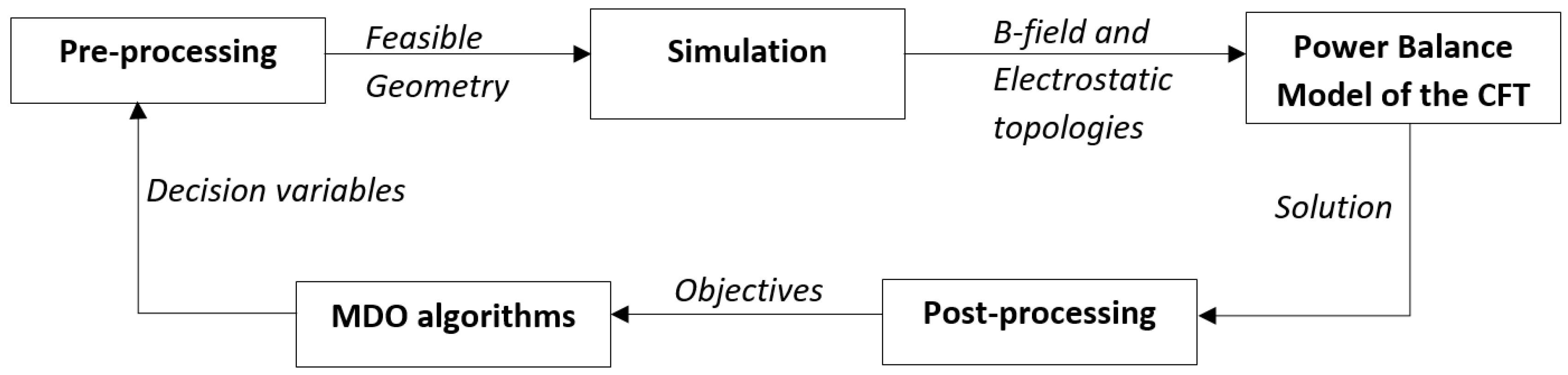
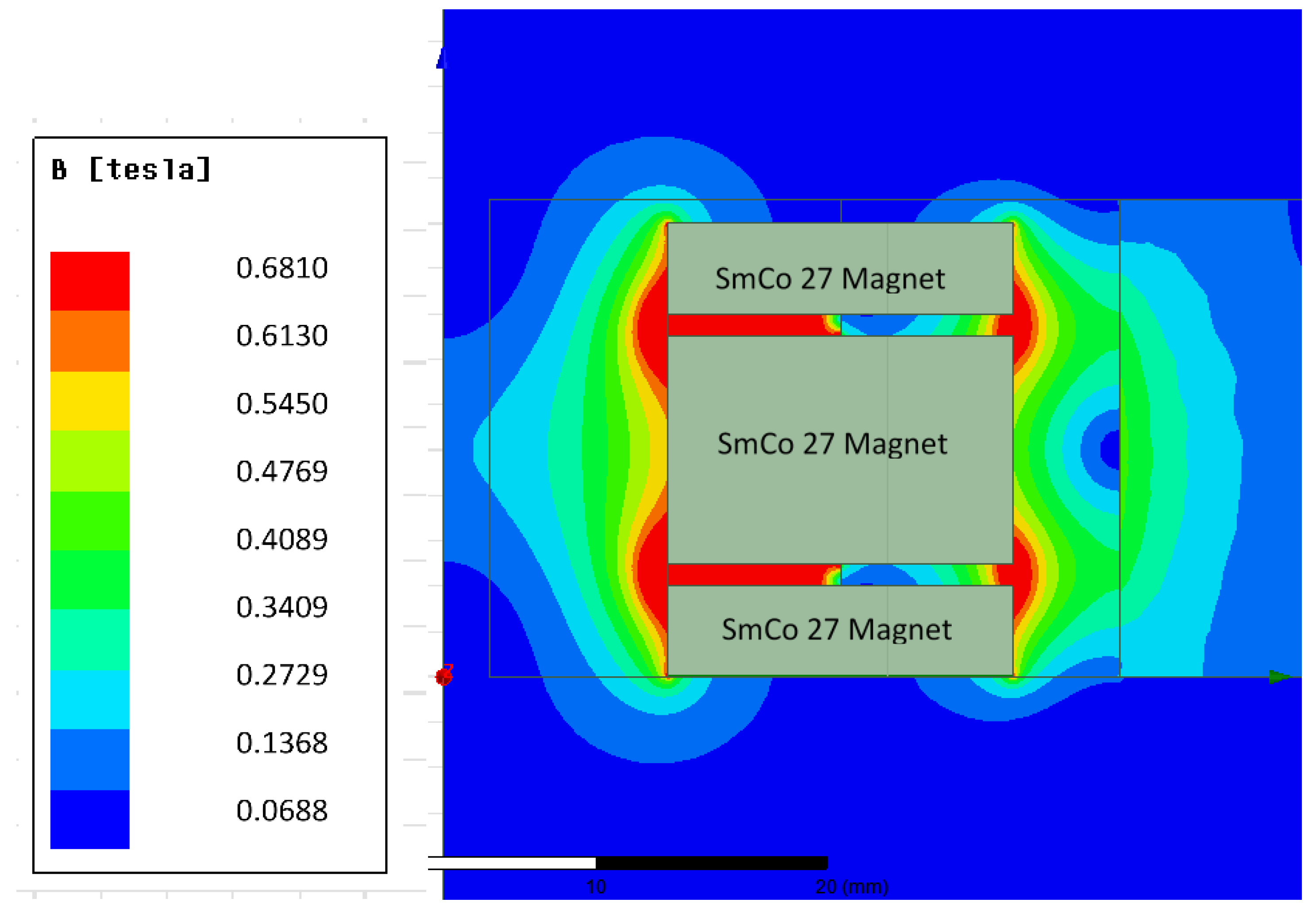
Figure 2.
Magnetic field strength topology of non-dominated solution, S1, from the results of the simulation.
Figure 2.
Magnetic field strength topology of non-dominated solution, S1, from the results of the simulation.

Figure 3.
Optimization results from MDO using analysis (at 40th generation with N = 64). The green points indicate the feasible geometries, the blue points are non-dominated solutions and the red crosses represent unfeasible solutions.
Figure 3.
Optimization results from MDO using analysis (at 40th generation with N = 64). The green points indicate the feasible geometries, the blue points are non-dominated solutions and the red crosses represent unfeasible solutions.

Figure 4.
Optimization results from surrogate-only MDO evaluations (at 100th generation with N = 100). The green points indicate the feasible geometries, and the blue points are non-dominated solutions.
Figure 4.
Optimization results from surrogate-only MDO evaluations (at 100th generation with N = 100). The green points indicate the feasible geometries, and the blue points are non-dominated solutions.

Figure 5.
Sensitivity of performance parameters to design parameters.

Figure 6.
Parallel coordinate plot for MDO using analysis (at 40th generation with N = 64). The green points and lines indicate feasible solutions, the blue point and lines indicate non-dominated solutions and frames indicate the range of solutions that have the same relationship with the corresponding objective and decision variables.

Figure 7.
Parallel coordinate plot for surrogate-only MDO (at 100th generation with N = 100). The frames indicate the range of solutions that have the same relationship with the corresponding objective and decision variables.
Figure 7.
Parallel coordinate plot for surrogate-only MDO (at 100th generation with N = 100). The frames indicate the range of solutions that have the same relationship with the corresponding objective and decision variables.

Figure 8.
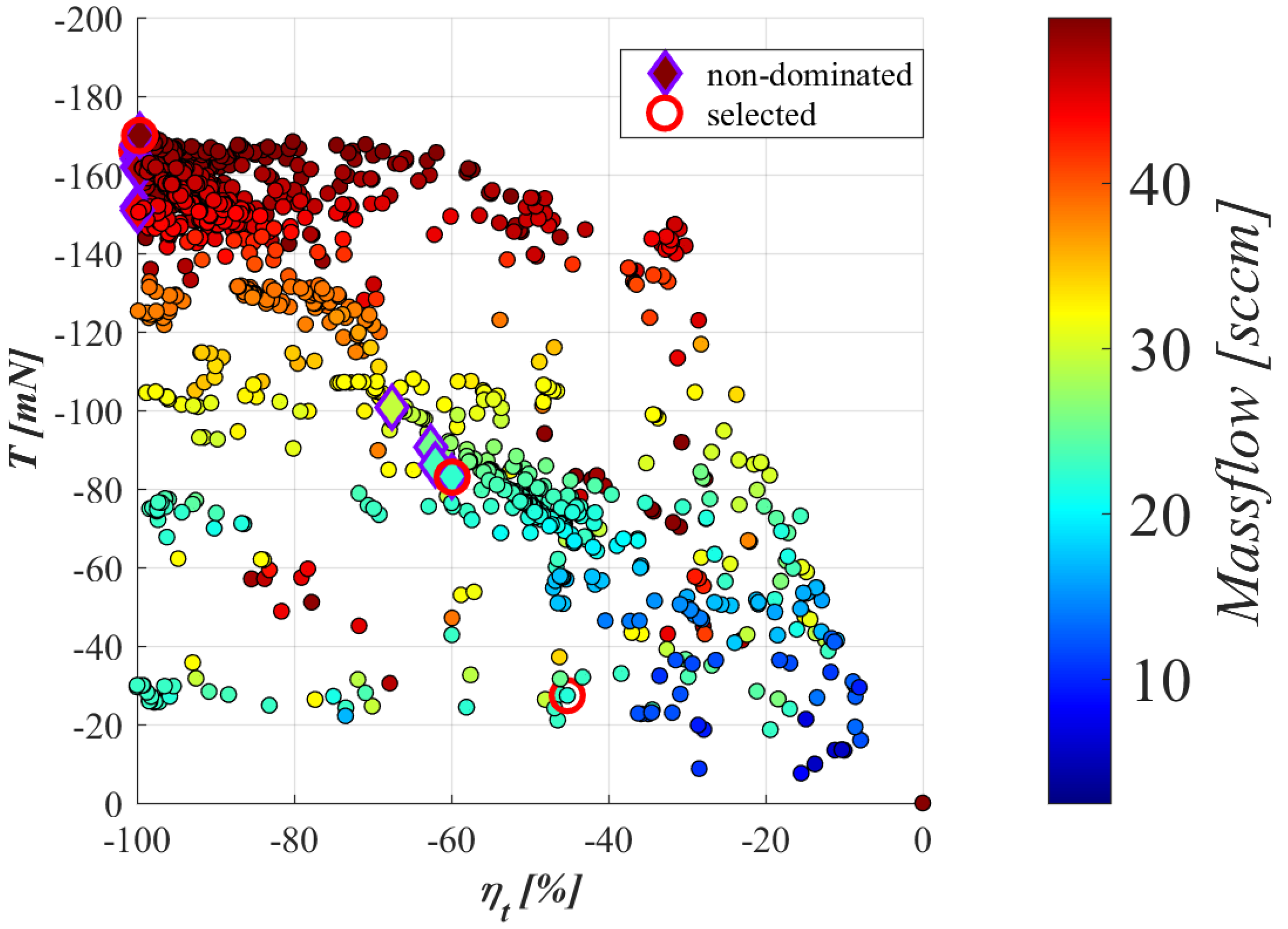
Anode potential color map of the feasible solutions with respect to thrust T and specific impulse Isp (the selected and non-dominated solutions are highlighted).
Figure 8.
Anode potential color map of the feasible solutions with respect to thrust T and specific impulse Isp (the selected and non-dominated solutions are highlighted).
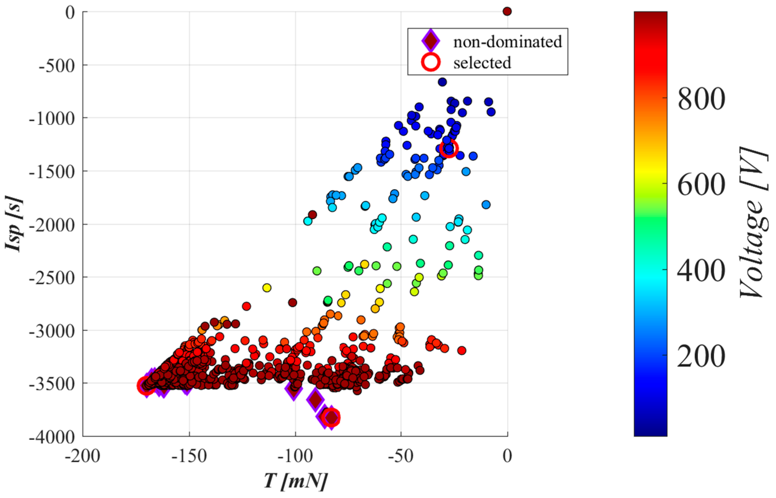
Figure 9.
Anode current color map of the feasible solutions with respect to efficiency ηt, thrust T and specific impulse Isp.
Figure 9.
Anode current color map of the feasible solutions with respect to efficiency ηt, thrust T and specific impulse Isp.
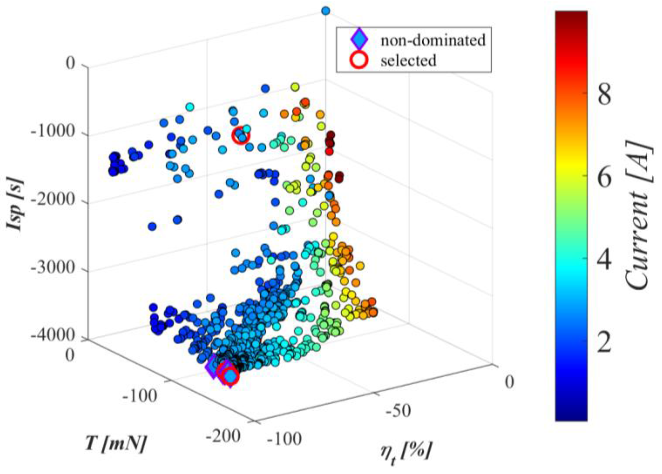
Figure 10.
Mass flow color map of the feasible solutions with respect to efficiency ηt and thrust T.
Figure 10.
Mass flow color map of the feasible solutions with respect to efficiency ηt and thrust T.

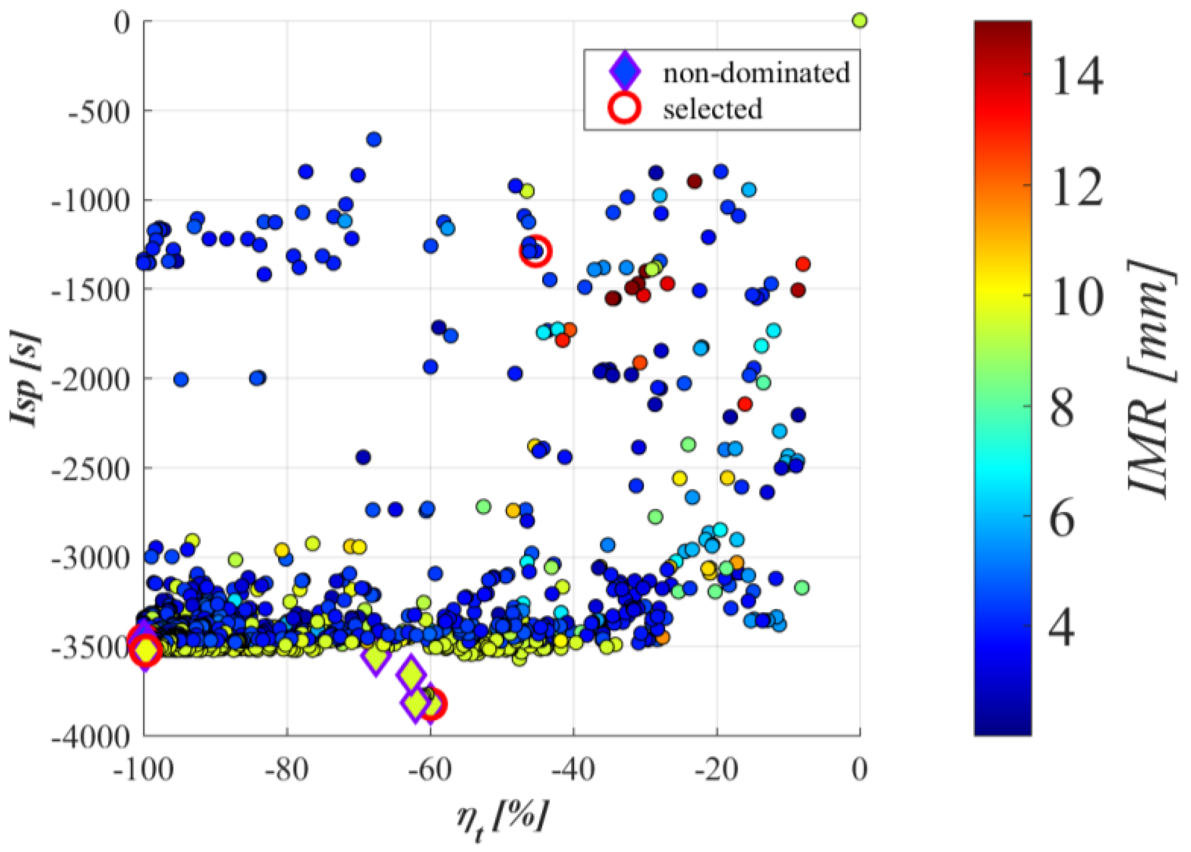
Figure 11.
Inner Magnet Radii color map of the feasible solutions with respect to efficiency ηt and specific impulse Isp.
Figure 11.
Inner Magnet Radii color map of the feasible solutions with respect to efficiency ηt and specific impulse Isp.


Table 1.
Magnetic cusp arrival probabilities.
| Cusp Probability | |
|---|---|
| C1 | 0.0167 |
| C2 | 0.0030 |
| C3 | 0.0259 |
| C4 | 0.0037 |
| Beam Efficiency | 0.8001 |
Table 2.
Comparison of experimental and simulated results.
| Propellant Mass Flow, ma (sccm) | Ma, et al. [9] | Present | |||||
|---|---|---|---|---|---|---|---|
| Total Efficiency | Specific Impulse, Isp (s) | Thrust (mN) | Total Efficiency | Specific Impulse, Isp (s) | Thrust (mN) | Thrust Error % | |
| 10 | 0.200 | 1971 | 19 | 0.2944 | 2368 | 22.83 | 16.78 |
| 20 | 0.330 | 2178 | 42 | 0.3913 | 2364 | 45.58 | 7.85 |
| 30 | 0.345 | 2282 | 66 | 0.3839 | 2356 | 68.12 | 3.11 |
| 40 | 0.350 | 2256 | 87 | 0.3850 | 2345 | 90.41 | 3.77 |
| 50 | 0.348 | 2324 | 112 | 0.3525 | 2317 | 111.69 | 0.28 |
Table 3.
Electrostatic plasma cell solution.
| Magnetic Cusp Cell Potential | Model Potential |
|---|---|
| Φ1 (Plume Potential) | 36.54 V |
| Φ2 (Exit Cell) | 373 V |
| Φ3 (Middle Cell) | 584 V |
| Φ4 (Anode Cell) | 387 V |
| Grid Efficiency | 0.9079 |
Table 4.
First-order indices for influences of design parameters on performance parameters.
| Parameter | Φa | Ia | ma | IMR | OMR |
|---|---|---|---|---|---|
| T | 0.015 | 0.084 | 0.050 | 0.018 | 0.072 |
| ηt | 0.007 | 0.051 | 0.026 | 0.042 | 0.153 |
| Isp | 0.009 | 0.097 | 0.034 | 0.036 | 0.167 |
Table 5.
Total-effect indices for influences of design parameters on performance parameters.
| Parameter | Φa | Ia | ma | IMR | OMR |
|---|---|---|---|---|---|
| T | 0.111 | 0.597 | 0.430 | 0.433 | 0.565 |
| ηt | 0.165 | 0.549 | 0.328 | 0.363 | 0.702 |
| Isp | 0.089 | 0.644 | 0.308 | 0.409 | 0.600 |
Table 6.
Selected design configurations.
| Solution | T (Mn) | ηt (%) | Isp (s) | Φa (V) | Ia (A) | ma (sccm) | IMR (mm) | OMR (mm) |
|---|---|---|---|---|---|---|---|---|
| S1 | 169.9 | 99.6 | 3526 | 999.9 | 2.94 | 49.98 | 9.91 | 25.10 |
| S2 | 166.2 | 99.9 | 3469 | 998.4 | 2.83 | 49.69 | 3.91 | 13.13 |
| S3 | 82.9 | 59.8 | 3825 | 997.8 | 2.61 | 22.51 | 9.59 | 22.97 |
| S4 | 27.4 | 45.2 | 1291 | 153.3 | 2.49 | 21.98 | 3.83 | 25.45 |
Table 7.
Adjusted selected design configurations based on acceleration, divergence efficiencies and multiply charged ions.
Table 7.
Adjusted selected design configurations based on acceleration, divergence efficiencies and multiply charged ions.
| Solution | T (mN) | ηt (%) | Isp (s) |
|---|---|---|---|
| S1 | 102.7 | 36.5 | 2131 |
| S2 | 100.5 | 36.6 | 2098 |
| S3 | 50.2 | 21.9 | 2313 |
| S4 | 16.5 | 16.5 | 778 |
Table 8.
Comparison of performance and design parameters.
| Performance Parameter | Present (S1) | Ma et al. [9] | Young et al. [8] | Courtney et al. [7] | Keller et al. [3] | Kornfeld et al. [5] |
|---|---|---|---|---|---|---|
| Efficiency (%) | 36.5 | 34.5 | 21.7 | 44.5 | 40.7 | 46 |
| Anode Potential (V) | 1000 | 500 | 300 | 550 | 1100 | 1000 |
| Anode Current (A) | 2.94 | 4.1 | 0.37 | 0.44 | - | 1.5 |
| Mass flow rate (sccm) | 50 | 30 | 8.2 | 8.5 | 0.48 | 15 |
| Thrust (mN) | 103 | 66 | 4.9 | 13.4 | 0.36 | 50 |
| Specific Impulse (s) | 2131 | 2287 | 1239 | 1640 | 860 | 3000 |
| Design Parameter | ||||||
| Inner magnet diameter (mm) | 19.82 | 40 | 17.5 | - | - | - |
| Outer magnet diameter (mm) | 50.2 | 64 | 47.8 | 64 | 30 | - |
| Chamber length (mm) | 50 | 96 | 39.7 | 40 | - | - |
| Magnet material | 2Sm17Co | 2Sm17Co | SmCo | 3212SmCo | SmCo | SmCo |
| Propellant | Xe | Xe | Kr | Xe | Xe | Xe |
| Chamber wall material | BN | BN | BN | BN | BN | BN |
© 2017 by the authors. Licensee MDPI, Basel, Switzerland. This article is an open access article distributed under the terms and conditions of the Creative Commons Attribution (CC BY) license (http://creativecommons.org/licenses/by/4.0/).
Share and Cite
MDPI and ACS Style
Fahey, T.; Muffatti, A.; Ogawa, H. High Fidelity Multi-Objective Design Optimization of a Downscaled Cusped Field Thruster. Aerospace 2017, 4, 55. https://doi.org/10.3390/aerospace4040055
AMA Style
Fahey T, Muffatti A, Ogawa H. High Fidelity Multi-Objective Design Optimization of a Downscaled Cusped Field Thruster. Aerospace. 2017; 4(4):55. https://doi.org/10.3390/aerospace4040055
Chicago/Turabian StyleFahey, Thomas, Angus Muffatti, and Hideaki Ogawa. 2017. "High Fidelity Multi-Objective Design Optimization of a Downscaled Cusped Field Thruster" Aerospace 4, no. 4: 55. https://doi.org/10.3390/aerospace4040055
Note that from the first issue of 2016, this journal uses article numbers instead of page numbers. See further details here.