Wake-Model Effects on Induced Drag Prediction of Staggered Boxwings

1
School of Engineering, RMIT University, Melbourne, Victoria 3000, Australia
2
Faculty of Aerospace Engineering, Ryerson University, Toronto, ON M5B2K3, Canada
*
Author to whom correspondence should be addressed.
†
Current address: Faculty of Aerospace Technology, FH Aachen University of Applied Sciences, 52064 Aachen, Germany.
Aerospace 2018, 5(1), 14; https://doi.org/10.3390/aerospace5010014
Submission received: 30 November 2017
/
Revised: 23 December 2017
/
Accepted: 12 January 2018
/
Published: 24 January 2018
(This article belongs to the Special Issue Feature Papers in Aerospace)
Abstract
:For staggered boxwings the predictions of induced drag that rely on common potential-flow methods can be of limited accuracy. For example, linear, freestream-fixed wake models cannot resolve effects related to wake deflection and roll-up, which can have significant affects on the induced drag projection of these systems. The present work investigates the principle impact of wake modelling on the accuracy of induced drag prediction of boxwings with stagger. The study compares induced drag predictions of a higher-order potential-flow method that uses fixed and relaxed-wake models, and of an Euler-flow method. Positive-staggered systems at positive angles of attack are found to be particularly prone to higher-order wake effects due to vertical contraction of wakes trajectories, which results in smaller effective height-to-span ratios than compared with negative stagger and thus closer interactions between trailing wakes and lifting surfaces. Therefore, when trying to predict induced drag of positive staggered boxwings, only a potential-flow method with a fully relaxed-wake model will provide the high-degree of accuracy that rivals that of an Euler method while being computationally significantly more efficient.
1. Introduction
Induced drag is an inviscid phenomenon and originates in the opposed spanwise flow patterns on the upper and lower wing surface that is the result of the spanwise pressure gradients of a finite wing generating lift. The impact on aircraft performance is profound. For a commercial aircraft, induced drag accounts for approximately 40% of the total drag during cruise flight and up to 90% during takeoff [1]. A marginal reduction in induced drag translates into considerable savings in fuel and emissions or facilitates a range extension. Considering indirect effects associated with an improved climb performance and a higher maximum takeoff mass, gains easily multiply [1]. Against the background of the objectives set in Flightpath 2050 [2], measures that provide lower induced drag support the efforts to attain a cutback in fuel consumption and climate reactive emissions.
A reliable induced drag prediction is thus important to attain efficient aircraft designs. This is true already within the conceptual design phase because initial drag estimations dictate the selection of specific concepts and affect the projected configuration dimensions and subsequent costs [3,4]. Commonly, induced drag is estimated using computational approaches based on linear potential-flow theory. These provide computationally inexpensive induced drag estimates of acceptable accuracy.
An experimental drag investigation is not practical during the early design phases, but also not feasible in principle to determine the induced drag, especially if higher-order wake effects are to be included [5]. A direct measurement of the induced drag is generally not possible. Drag measurements contain the total drag that is composed of friction drag, pressure drag and induced drag. Pressure drag and friction drag are both associated with viscosity. In order to determine the induced drag, the contribution of the pressure drag and friction drag part must be separated by means of two-dimensional measurements of airfoil sections. This however cannot be done with sufficient accuracy to permit investigations into higher-order wake effects [5], but results in induced drag estimates that contain three-dimensional pressure drag and friction drag contributions.
More generally, an accurate experimental investigation is prevented by the viscosity inherent to real flow. Because tangential velocities around the side-edge of a wingtip can become very large, a viscosity induced flow separation occurs. This causes initial roll-up of the wake and shifts the tip vortex inwards [6], ultimately altering the trailing wake shed compared to an inviscid computational solution. Acknowledging that it is the wake shape and its vorticity that define the induced drag [6], it is apparent that the induced drag in a real, viscous flow and in a theoretical, inviscid flow-simulation is fundamentally different.
Highly non-planar configurations, such as boxwings or c-wings, have the potential to significantly reduce induced drag and, thus, have repeatedly been in the focus of research [7,8,9,10,11,12]. The inviscid aerodynamic advantage of these configurations can primarily be related to the bound circulation being distributed over a larger effective wingspan. This lowers the spanwise loading and reduces the average downwash velocity of the system compared to that of an optimally-loaded planar wing of equivalent span and lift [1]. Based on linear potential-flow theory, the boxwing achieves the highest span efficiency or lowest induced drag for a given projected wingspan and lift [7,13,14,15,16,17,18].
1.1. Problem Definition
In order to fully asses the overall performance of a boxwing design, an accurate induced drag prediction method is a prerequisite despite their clear induced drag advantage over equivalent planar systems. Their total aerodynamic performance must be evaluated as a trade-off between induced drag and contributions of other drag sources. For example, viscous drag penalties, associated with the increased wetted area, diminish the advantage of induced drag savings [1,19]. For highly non-planar configurations, potential-flow induced drag predictions can have limited accuracy. Excluding compressiblity effects, this is primarily related to the linear freestream-fixed wake model that insufficiently captures higher-order wake effects. Higher-order wake effect are considered as the roll-up and deformation of the physical and force-free wake compared to the freestream-fixed wake model. These can have significant impacts on the analysis of highly non-planar configurations [20].
The influence of these effects is dependent on the freestream angle of attack and the geometrical arrangement of the lifting surfaces, in particular on height-to-span ratio and stagger. With regards to height-to-span ratio, the sensitivity to higher-order wake effects is certainly more pronounced for near-planar multi-surface configurations and progressively reduces with larger vertical separations. Nevertheless, the effective vertical gap reduces for positive staggered systems with increasing freestream angle of attack. This may therefore lead to stronger higher-order wake effects. As inferred from the wake substitution concept [6], especially the influence of the longitudinal arrangement is decisive for highly non-planar configurations like the boxwing. Stagger is favorable for practical applications of the boxwing concept to attain high aerodynamic efficiency under static longitudinal stability and trim constraints [10]. It also easily results in significant wake roll-up and deflection between the trailing edges of two staggered lifting surfaces.
1.2. Contribution of Present Work
The present work explores the impact that trailing wake models of a potential-flow approach have on the accuracy of induced drag predictions for boxwings with stagger. Besides quantifying the extent of higher-order wake effects in correlation to the stagger factor and the angle of attack, the underlying physical mechanisms are explored in order to gain deeper insight into the impact that higher-order or surrogate wakes have. The relaxed-wake results are compared with the predictions of an Euler method. This high-fidelity, inviscid method allows the assessment of the accuracy of more simplistic potential-flow methods that use surrogate wake models. The present new knowledge may subsequently be used to develop design guidelines that take advantage of wake effects and enable performance achievements beyond linear theory.
2. Relevant Theory
The boxwing represents the limiting case of a mutli-plane with an infinite number of lifting surfaces [13]. Based on lifting-line theory [21], its optimum span efficiency factor is approximated as follows [13]:
The optimum span efficiency factor of Equation (1) solely dependents on the height-to-span ratio [13]. Similar correlations between optimum span efficiency and height-to-span ratio have been presented in other references [14,15,16,17,18,22,23,24,25]. Although the asymptotic behavior of Equation (1) is unclear [14,17,18], the expression agrees well with references [16,24] and generally is sufficient to approximate the optimum span efficiency factor for the practical range of height-to-span ratios. For other closed configurations, the variation of the optimum span efficiency factor with the vertical extent of the system and minimum induced drag conditions were discussed by Cone [23].
Induced drag minimizations for boxwings were performed by von Karman [26], who also provided an illustration of associated spanwise loadings. Optimum circulation distributions were formally derived in references [17,18] and qualitatively confirmed the minimum induced drag conditions that were assumed by Frediani and Montanari [24]. For small vertical separations of practical interest, the optimal distribution is approximately composed of a constant and an elliptical part for both horizontal wings, whereas on the vertical wings a butterfly-type shape is adopted. However, the shape of the optimum distribution depends on the height-to-span ratio [17,18]. In particular, with increasing height-to-span ratios, the spanwise distribution of horizontal wings is affected by a constant term, whereas in the case of the vertical wings a linear term becomes dominant. Moreover, the optimum circulation for boxwings is not unique [1,15,18,25]. Because induced drag is directly related to the gradients of circulation, a constant amount of circulation can be added without an induced drag penalty [18].
Based on lifting-line theory and provided that the circulation distribution on each individual surface is maintained, reference [27] shows that the streamwise separation between the lifting elements can be varied arbitrarily without changing the total induced drag of the system. It is referred to as Munk’s Stagger Theorem. Despite being widely accepted, formal difficulties with the application of this concept do exist. Due to the representation with a single bound vortex, the wake shed at the trailing edge is commonly not equivalent to the quarter-chord condition that is assumed by classical lifting-line theory [28]. The validity of the stagger theorem is therefore limited to the lifting-line concept and in particular to the freestream-fixed wake model. Reference [20] shows that a derivation of the stagger theorem based on the lifting-line concept is unnecessarily restrictive and presents a more general approach by means of momentum conservation. The induced drag is found to be dependent only on the shape of the wake and its vorticity distribution, rather than the shape of the lifting-line. This indicates a difference towards lifting-line theory, but is still within linear potential-flow theory [6].
A key-design parameter of boxwings is the geometric height-to-span ratio that gives the relative vertical distance between the trailing edges of the system. Another parameter is the stagger factor that describes the longitudinal separation between the trailing edges of the horizontal lifting surfaces normalized by the reference chord length ( m). It is considered to be positive if the upper wing is translated in the streamwise direction. The reference chord is defined as the mean chord of the isolated wing. Both, the geometric height-to-span ratio and the stagger factor are described in a body-fixed -reference frame. In contrast to other research efforts, in the herein presented work the distinction is made between the geometric height-to-span ratio (i) , the freestream height-to-span ratio (ii) and the effective height-to-span ratio (iii) [29]. The freestream height-to-span ratio is defined as the relative vertical extent of the system trailing edges perpendicular to the freestream velocity vector, whereas the effective height-to-span ratio gives the relative aerodynamic gap of the trailing wake trace on a downstream partition surface. The partition coincides with the most downstream trailing edge of the system.
3. Computational Models
3.1. Test Cases
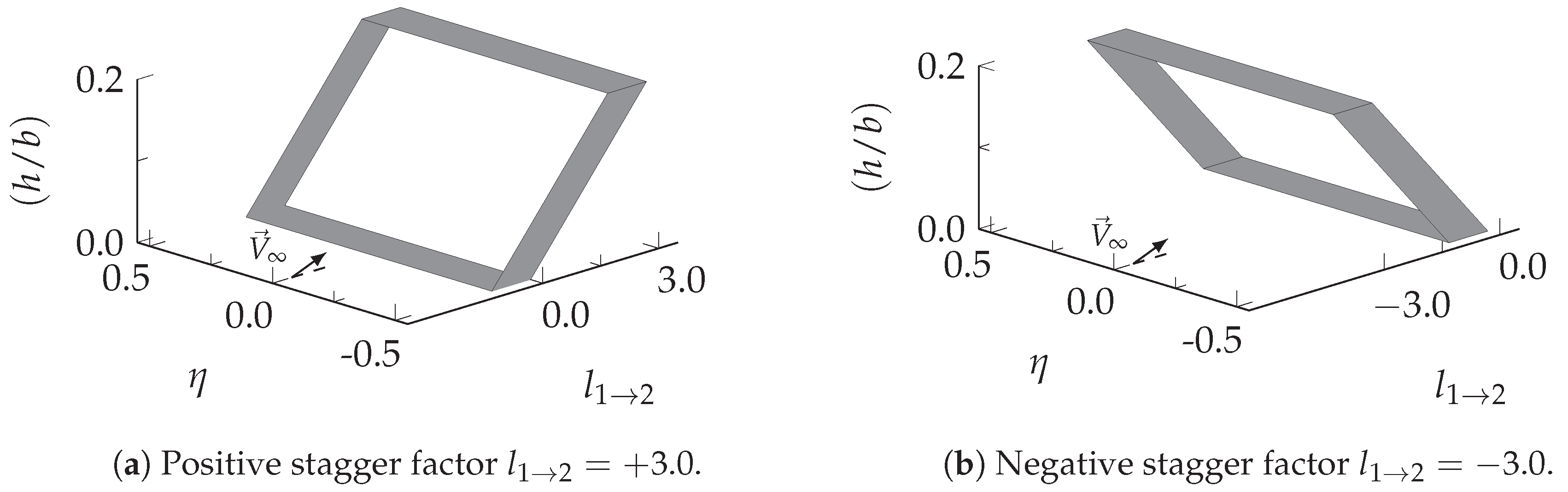
Two simplified boxwing configurations with single wing aspect ratios of and positive or negative stagger factor were investigated under subsonic flow conditions. Their individual planforms are depicted in Figure 1. Closed lifting concepts with similar geometric characteristics were considered in references [30,31,32]. The lifting systems are composed of two equivalent horizontal wings of constant chord length, that are connected by two joints at their wing-tips to form a closed, box-like and continuous surface. In this study, wing sweep, which in essence is a form of stagger, was omitted in order to focus on induced drag effects purely due to stagger. Moreover, the lifting surfaces do not incorporate camber, incidence or twist. Of course, in order to attain high aerodynamic efficiencies, a careful design and selection of these parameters is required [33], which is, however, not an objective of the herein presented study. Camber, wing incidence and twist may affect the relative sensitivity of induced drag and freestream angle of attack in dependency of the stagger factor, which likely prevents general conclusions of these correlations. The optimal spanwise load distribution of reference [18] is therefore not adopted, but also not required in order to investigate the impact of the selected wake-model approach on the induced drag prediction.
Stagger factors of between the trailing edges of the horizontal lifting surfaces were used herein. These limits a realistic representation of the possible range of streamwise separations. A height-to-span ratio value of was selected, which is similar to that of other references [7,11,31,32,34,35]. The lifting surfaces of the higher-order potential-flow model have zero thickness, whereas the Euler-flow model uses a thin and symmetrical NACA 0004 airfoil.
3.2. Higher-Order Potential-Flow Model
A higher-order potential flow method was used to model the lifting surfaces and their wakes using Distributed Vorticity Elements (DVE). These trapezoidal sub-elements are planar, infinitely thin and consist of a vortex filament along their leading and trailing edges, which are connected by a vortex sheet. The lifting surfaces are represented by arranging several DVEs across the chord and span. Dependent on the stagger and the selected wake model, about 12–16 chordwise elements and 10–16 spanwise elements were used.
The main advantage of the chosen method over conventional potential-flow methods is its numerical stability. A continuous vortex sheet represents the shear layer coming off the wing. As a consequence of the continuous vortex sheet model, many of the singularity issues are avoided that are otherwise typical for vortex-filaments representations. In the chosen model, the wake is modeled either as a prescribed, drag-free or relaxed, force-free wake. It evolves using a time-stepping scheme.
The lift is computed along the continuous lifting lines that represent the wing, whereas the induced drag is estimated by taking the cross product between the circulation that is shed into the wake at the trailing edge and the velocity induced by the wake at this spanwise location [36,37]. A detailed discussion of the method is given in references [37,38].
3.3. Euler-Flow Model
The three-dimensional Euler equations were solved by means of the commercially-available, cell-centered finite volume method STAR-CCM+, version 8.04.010 [39]. The spatial discretization of the convective flux terms involved a second-order upwind scheme. Gradient computations were based on a hybrid-Gauss least-squares method along with a Venkatakrishnan gradient reconstructing limiter approach. The segregated-flow model was used.
The lift is computed by means of a surface pressure integration, whereas induced drag predictions are based on a wake integration technique [40]. This is required because artificial viscosity, whether introduced explicitly for stability reasons or implicitly due to mesh coarsening, affects the surface pressure distribution especially near the leading and trailing edge of the wing, which distorts the induced drag prediction [41]. The wake integration technique computes the induced drag by means of a transverse plane (TP) that is located downstream of the lifting element as indicated in Figure 2.
However, the induced drag progressively decays as the transverse plane is moved downstream. This is related to the creation of spurious entropy drag due to artificial viscosity and grid coarsening downstream of the wing, numerically smearing the vortical wake. In order to correct the farfield induced drag, the so-called axial velocity defect is separated into components correlating to reversible or irreversible flow phenomena [40]. In an inviscid and subsonic flow, spurious entropy drag represents the only irreversible source, whereas induced drag is related to a reversible process. Employing thermodynamic properties, the axial velocity defect due to reversible phenomena can be described as follows:
The induced drag on a transverse plane is given by:
with the vector :
The spurious entropy is computed by a volume integration that contains only the trailing wake bound between the trailing edge of the wing and the transverse plane (TP) as indicated in Figure 2.
with the irreversible axial velocity defect :
However, the estimation of the irreversible axial velocity defect based on Equation (6) is problematic as noted by reference [42]. The radical may become negative at some location within the domain and prevent a computation. Another possibility is indicated in [43] and shows that:
As discussed in reference [40], this approach is preferred, as the vector exhibits a smoother distribution within the computational domain. This finally leads to the expression for the spurious entropy drag in the wake:
The corrected induced drag is then found by:
A trimmed-cell approach was selected to create predominately hexahedral, Cartesian-type grids. The spatial convergence was investigated applying a constant grid refinement factor of . This did produce cell counts between approximately and . An asymptotic convergence criterion was established that required an induced drag variation of less than for 100 consecutive iterations for each individual grid level. The computed grid convergence index [44] for the three finest consecutive grid levels approached one, which confirms the solution to be within the asymptotic range of convergence.
The accuracy of the implemented wake integral approach was investigated by means of well-documented planar reference systems in reference [45]. Span efficiency factors attained for the elliptical wing, the crescent wing and the split-tip wing [6] are found to be in excellent consistency with relevant theory and other references.
4. Results and Discussion
4.1. Spanwise Load Distribution
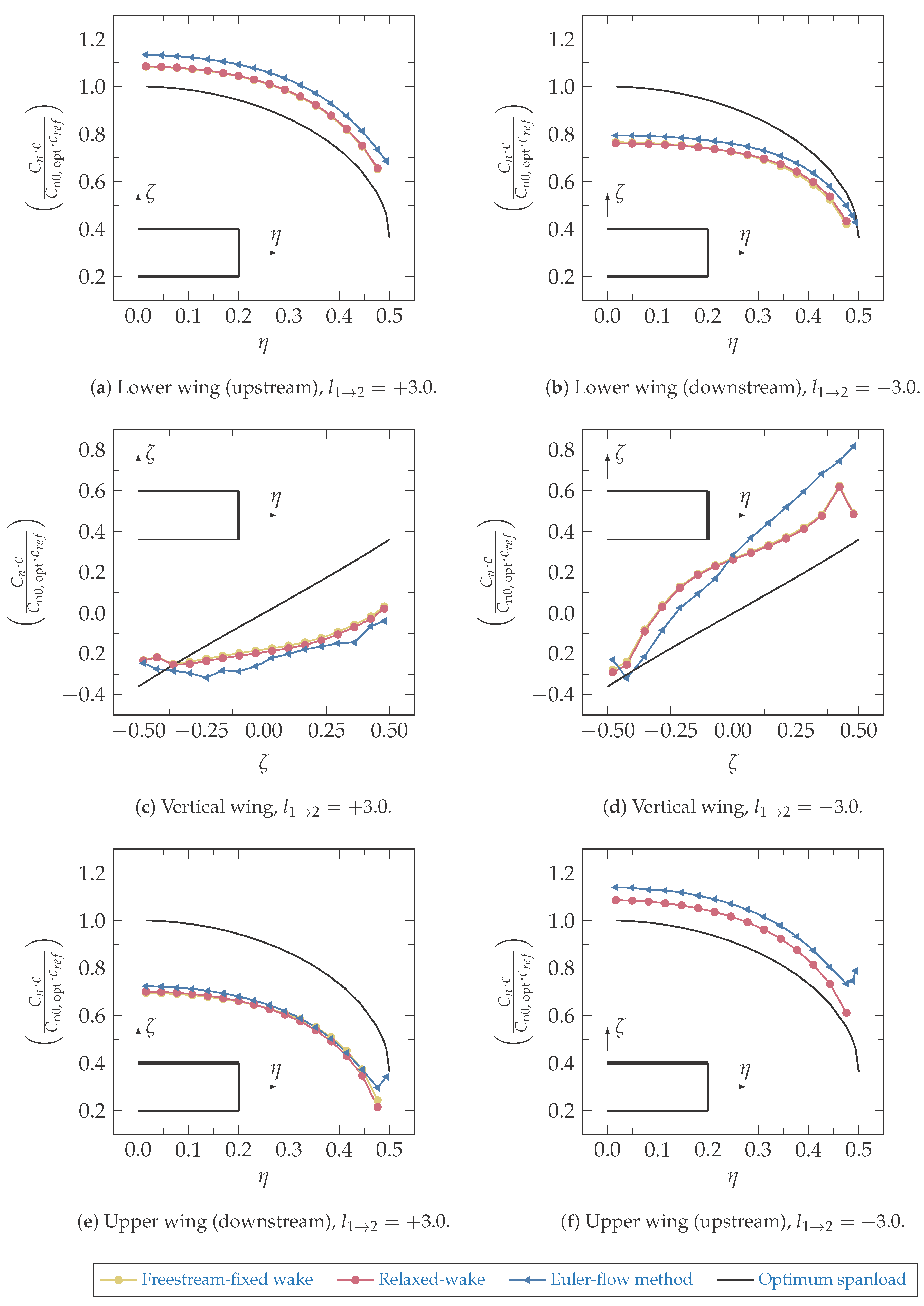
The spanwise load distributions that are based on the calculations using the higher-order potential-flow method and the Euler solver, are shown in Figure 3 for the positive and negative-staggered system. For the chosen vertical wing separation, the optimum loadings over both horizontal wings resembles a superposition of a constant and an elliptical distribution, whereas on the vertical wings, the spanwise lift-distribution can be approximated by a constant and a cubic term [17,18].
Compared to the optimal condition, the predicted loadings of the horizontal surfaces are offset, in particular of the downstream lifting surfaces, which is due to the stagger and results in an unequal lift division between the upper and lower surfaces. This also affects the loading on the vertical wings. Although an uneven load distribution between the two horizontal surfaces does not necessarily preclude the achievement of minimum induced drag, [17,18,25], the shown loadings do not comply with the theoretically optimum distribution. This is inherently related to the constant chord distribution of the lifting surface without twist.
The spanwise load distributions are found virtually identical independently whether a relaxed or fixed-wake model was used, which suggests a very limited sensitivity of lift to the choice of wake model. A reasonable similarity exists with spanwise lift distributions that were determined using the Euler-flow solver. Any differences between potential-flow and Euler-predictions, can be attributed to thickness effects, which result in a steeper lift curve slope in the case of the Euler-flow approach.
4.2. Computed Span Efficiency Factor
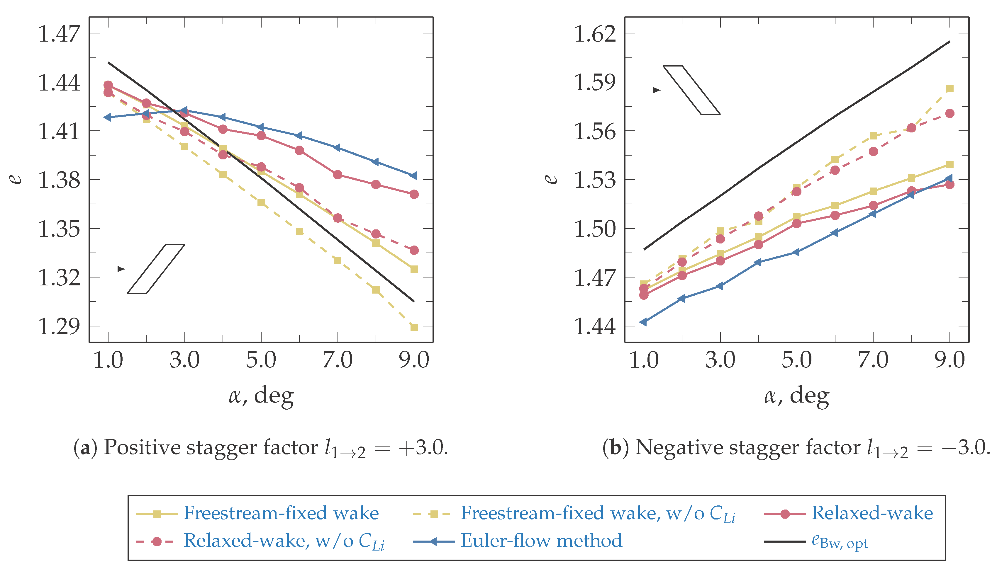
Computed span efficiency factors are presented in Figure 4. In general, for any positive angle of attack, negative stagger facilitates higher span efficiency factors than equivalent positive stagger. This is due to the larger effective height-to-span ratios of a negative-staggered wing arrangement [31,32,46,47,48].
For the system with positive stagger the span efficiency decreases as the freestream angle of attack increases. This conforms to the progressive reduction in effective height-to-span ratio and efficiency with increasingly positive angle of attack. The relaxed-wake model under-predicts Euler-based span efficiencies, but provides improved agreement compared to the fixed-wake model. With regards to the relaxed-wake model and the Euler-flow reference, the freestream-fixed wake approach under-estimates the span efficiency factor especially at higher angles of attack. This is caused by the roll-up and deflection of the physical, force-free wake, which results in wing-wake inferences that differ from those of the freestream-fixed surrogate. The relative deviation between freestream-fixed and relaxed-wake model predictions at equivalent angles of attack quantify the extent of the higher-order wake effects. For a freestream angle of attack of , the relative error in span efficiency constitutes approximately .
In the case of negative stagger, the span efficiency increases as the freestream angle of attack increases. The predictions that are based on the freestream-fixed and relaxed-wake model show good agreement with the Euler-flow reference. In contrast to the positive stagger case, the three different models exhibit much smaller differences in their span efficiency predictions for negative stagger. This indicates, that higher-order wake effects have less significant impacts on the performance. At an angle of attack of the relative error amounts to .
Acknowledging that the spanwise load distributions of present configurations are non-optimal, it is sensible to assess the computed span efficiency factors with regards to the linear theoretical optimum that is based on the approximation given by Equation (1). For equivalent freestream height-to-span ratios , theoretical optimum span efficiency factors are given in Figure 4. These confirm that for a fixed geometric height-to-span ratio and a positive freestream angle of attack, negative stagger facilitates higher span efficiencies than an equivalent positive stagger. Thus, it is sufficient to assume that the advantage of negative stagger is essentially caused by larger effective vertical gaps, rather than being an artifact of non-optimal loadings. The assumption to neglect any camber, incidence or twist does not affect the general applicability of these findings.
In the case of the negative-staggered system and independent on the freestream angle of attack or computational methodology, considerably smaller than optimum span efficiency factors are evident, which is consistent with the non-optimal spanwise loadings described in Figure 3. Limited to small angles of attack, this is also correct for the positive-staggered system, whereas predictions at higher angles of attack actually exceed the theoretical optima. For the relaxed-wake model and the Euler-flow reference, this can partially be attributed to higher-order wake effects.
The approximate relation given by Equation (1) is based on the lifting-line concept, which neglects induced lift effects [5]. These are caused by streamwise velocity inductions due to the non-planar character of the lifting system. Induced lift effects progressively gain impact as the angle of attack and/or stagger are increased. Opposed to negative stagger, a positive streamwise separation results in a positive induced lift contribution and, thus, in an overall lift increase, without affecting induced drag [5].
Generally, the upstream wing carries more lift than the downstream wing, independently of stagger. This results in an overall greater influence of velocities that the upstream wing induces [49], which is further dependent on the vertical joint arrangement. For the positive-staggered system, the joint of the upstream wing is oriented in the upward direction, which induces an outboard spanwise flow component, subsequently increasing the streamwise velocity and lift [49,50]. In contrast to that, the downward orientation of the joint for the upstream wing of the negative-staggered system reduces the streamwise flow component and induces negative lift.
Excluding induced lift, estimates of span efficiencies that are based on freeestream-fixed wakes result in smaller than optimal efficiencies, which is in consistent with non-optimal spanwise loadings of Figure 3. In the case of positive stagger, the relaxed-wake model yield span efficiencies that exceed the linear optimum of Equation (1) at angles of attack beyond . This is a consequence of higher-order wake effects. In the case of the negative-staggered system, neglecting induced lift effects increases the span efficiency, but still does lead to smaller than optimum estimates. The relative deviation in span efficiency between the freestream-fixed and the relaxed-wake model is not affected by induced lift.
4.3. Wake Traces on Partition Surface
An investigation of wake traces was conducted to substantiate the findings of the previous section. The particular objective of this section is to build a correlation between system efficiency and wake trace.
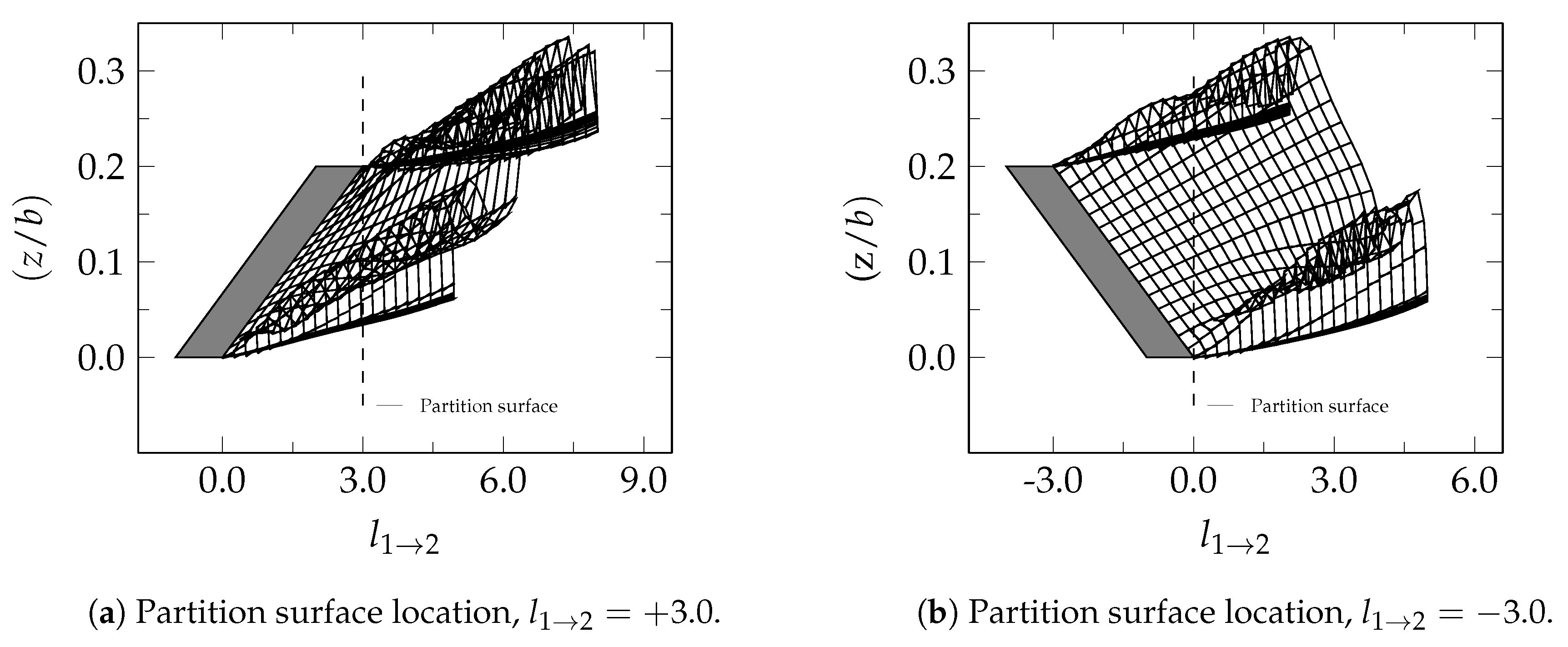
The spanwise loading and therewith the vorticity shed in the wake is independent on the wake model selection (compare Figure 3). In that case, the induced drag of a wing is defined only by its wake trace on a transverse partition surface [6]. As a consequence of the wake substitution concept [6], the partition surface must be located downstream of the lifting system and coincide with its most downstream trailing edge as indicated in Figure 5.
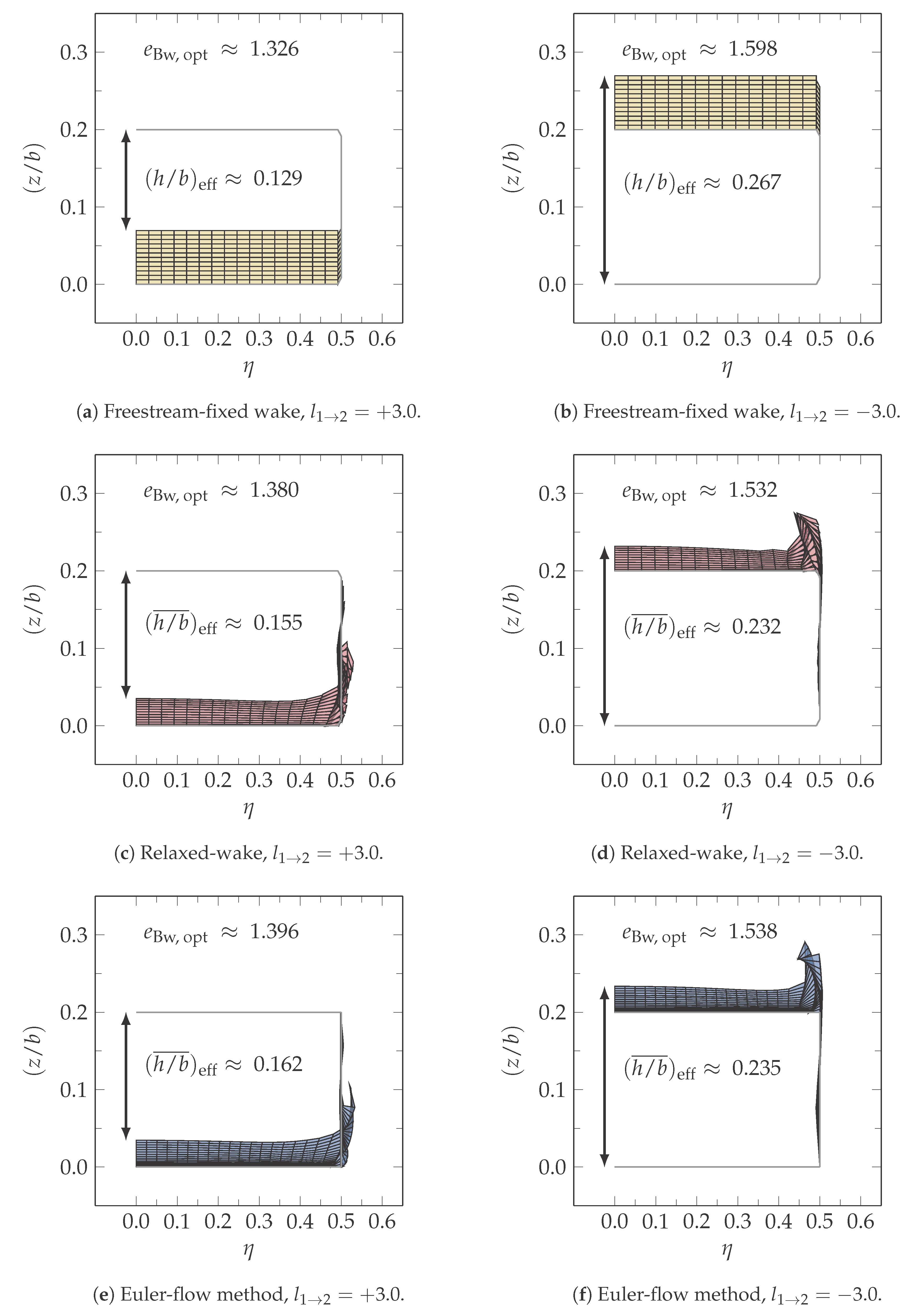
For the positive-staggered system this is the trailing edge of the upper wing, where it is the trailing edge of the lower wing in the case of negative stagger. In Figure 6 are shown the traces of the vortex-sheet wakes and shear layers that were predicted using the freestream-fixed and relaxed-wake model of the potential-flow method and the Euler-method, respectively. Because of the location of the partition surface, only the wake traces of the upstream wing are relevant and shown here.
The height-to-span ratio is a measure for the system efficiency [29]. In order to correlate the system efficiency with the wake trace, an effective height-to-span ratio was calculated on the partition surface. The effective height-to-span ratio is the relative vertical distance between the wake shed from the upstream wing and the trailing edge of the downstream wing, measured perpendicular to the freestream direction [29]. The effective height-to-span ratio is constant along the wing span for the freestream-fixed wake model, but is a function of the spanwise location in the case of the relaxed-wake model and the Euler-flow solution. A mean value of the effective height-to-span ratio is used in the case of the relaxed-wake model and the Euler-simulation. The effective height-to-span ratio can then be used to provide an approximation of the system efficiency based on Equation (1).
Based on a visual assessment, an excellent geometrical consistency is evident among the relaxed-wake trace and the Euler-flow reference. Employing the effective height-to-span ratio as valuation basis, it becomes apparent, that the effective vertical gap differs considerably in dependency of the employed wake model. For the freestream-fixed wake model, the effective vertical gap is constant across the relative span, where it is a function of the spanwise location in the case of the relaxed-wake model and the Euler-flow reference. Consistent with span efficiency predictions, the effective vertical gap reduces for positive and increases for negative stagger at positive freestream angles of attack. Approximations of the span efficiency factor based on Equation (1) and an average value of the effective vertical gap at the partition surface are additionally provided in Figure 6. A reasonable qualitative agreement exist with computational results.
With regards to higher-order wake effects, it is found that wake deflection is the predominant contribution in the case of the positive-staggered system. The force-free wake shape is aligned with the local flowfield, which leads to a larger effective height-to-span ratio and, hence, better efficiencies than compared to the freestream-fixed wake. In addition, the vertical wing effectively mitigates roll-up effects at the tip and also induces a spanwise velocity component, increasing the effective span by shifting the tip vortex slightly outboards [51].
For the negative-staggered case the influence of wake deflection results in smaller effective height-to-span ratios than for the freestream-fixed wake, potentially leading to smaller span efficiencies as well. In contrast to the positive-staggered system, the contribution of the wake roll-up of the tip-vortex is more pronounced and results in two opposing effects. The roll-up increases the effective height-to-span ratio especially in the tip region where the effect of vertical separation is most effective [28]. However, also, related to the downward orientation of the vertical wing, actually produces a spanwise contraction of the wake [51], which reduces the effective span and increases induced drag. Despite substantial differences in average effective height-to-span ratio between the freestream-fixed wake, the relaxed-wake and the Euler-flow reference, the opposing effects of wake roll-up and deflection ultimately result in similar span efficiency estimates.
5. Conclusions
Under certain conditions, higher-order wake effects are confirmed to impact on the span efficiency of a system especially when compared to freestream-fixed wake predictions. This difference in prediction results is attributed to the deflection and roll-up of the force-free wake, which alters the effective height-to-span ratio of the system, and, therefore the induced drag prediction. The sensitivity of the system to higher-order wake effects depends on the direction of the longitudinal separation. The positive-staggered system is found particularly prone to higher-order wake effects, due to the vertical contraction of wake trajectories, that lead to smaller effective height-to-span ratios, and, thus closer interactions between trailing wakes and lifting surfaces. At positive angles of attack, computations using the freestream-fixed wake model predict lower span efficiencies than the relaxed-wake model and Euler-flow predictions. The deviation between both wake models is less pronounced for the negative-staggered system. It is thus concluded that a relaxed, force-free wake model is compulsory to enable accurate induced drag predictions when using a potential-flow method for the analysis of boxwings with significant positive stagger.
Acknowledgments
This research was greatly supported by Jonathan H. Watmuff (RMIT University). Special thanks also go to J.-Michael Bauschat and Thomas Esch (both FH Aachen University of Applied Sciences).
Author Contributions
Julian Schirra implemented the farfield induced drag estimation for the Euler-based flow model, conducted the relevant computational studies and wrote the present paper. William Bissonnette and Götz Bramesfeld provided several modifications to the source code of the higher-order potential-flow model to improve its accuracy, performed additional validation studies and assisted in writing the paper.
Conflicts of Interest
The authors declare no conflict of interest.
Abbreviations
The following abbreviations are used in this manuscript:
| b | Wing span |
| Sectional normal force coefficient | |
| Optimum sectional normal force coefficient | |
| c | Chord length |
| Reference chord length | |
| Longitudinal trailing edge separation | |
| Induced drag | |
| Span efficiency factor | |
| Height-to-span ratio | |
| L | Lift |
| Stagger factor | |
| Freestream stagnation pressure | |
| Freestream velocity | |
| x, y, z | Cartesian coordinates |
| Freestream angle of attack | |
| Circulation | |
| Non-dimensional wing span | |
| Single wing aspect ratio | |
| Freestream air density | |
| Non-dimensional height |
References
- Kroo, I.M. Drag due to Lift: Concepts for Prediction and Reduction. Annu. Rev. Fluid Mech. 2000, 587–617. [Google Scholar] [CrossRef]
- Darecki, M.; Edelstenne, C.; Enders, T.; Fernandez, E.; Hartman, P.; Herteman, J.P.; Kerkloh, M.; King, I.; Ky, P.; Mathieu, M.; et al. Europe’s Vision for Aviation: Maintaining Global Leadership and Serving Society’s Needs; European Commission: Luxembourg, 2011. [Google Scholar]
- Cummings, R.M.; Morton, S.A.; Mason, W.H.; McDaniel, D.R. Applied Computational Aerodynamics: A Modern Engineering Approach; Cambridge Aerospace Series; Cambridge University Press: Cambridge, UK, 2015. [Google Scholar]
- Thokala, P.; Scanlan, J.; Chipperfield, A. Framework for Aircraft Cost Optimization Using Multidisciplinary Analysis. J. Aircr. 2012, 49, 367–374. [Google Scholar] [CrossRef]
- Schmidt-Göller, S. Zur Genauen Berechnung des Induzierten Widerstandes von Tragflügeln. Ph.D. Thesis, University of Stuttgart, Stuttgart, Germany, 1992. [Google Scholar]
- Smith, S.C. A Computational and Experimental Study of Nonlinear Aspects of Induced Drag. Ph.D. Thesis, Stanford University, Stanford, CA, USA, 1995. [Google Scholar]
- Frediani, A. The Prandtl Wing. In VKI Lecture Series: Innovative Configurations and Advanced Concepts for Future Civil Aircraft; von Karman Institute: Rhode Saint Genese, Belgium, 2005. [Google Scholar]
- Seywald, K.; Hellmundt, F.; Wildschek, A.; Holzapfel, F. Airworthiness Investigation of a Highly Nonplanar Flexible Wing Concept. In Proceedings of the 29th Congress of the International Council of the Aeronautical Sciences, St. Petersburg, Russia, 7–12 September 2014. ICAS Paper 2014-0088. [Google Scholar]
- Salam, I.R.; Bil, C. A Methodology for Multi-Disciplinary Analysis of the Box Wing Concept. In Proceedings of the 33rd AIAA Applied Aerodynamics Conference, Dallas, TX, USA, 22–26 June 2015. AIAA Paper 2015-3003. [Google Scholar]
- Andrews, S.A.; Perez, R.E. Parametric Study of Box-Wing Aerodynamics for Minimum Drag Under Stability and Maneuverability Constraints. In Proceedings of the 33rd AIAA Applied Aerodynamics Conference, Dallas, TX, USA, 22–26 June 2015. AIAA Paper 2015-3291. [Google Scholar]
- Gagnon, H.; Zingg, D.W. Aerodynamic Optimization Trade Study of a Box-Wing Aircraft Configuration. In Proceedings of the 56th AIAA/ASCE/AHS/ASC Structures, Structural Dynamics and Materials Conference, Kissimmee, FL, USA, 5–9 January 2015. AIAA Paper 2015-0695. [Google Scholar]
- Skinner, S.N.; Zare-Behtash, H. Aerodynamic Optimisation of Non-Planar Lifting Surfaces. In Proceedings of the 57th AIAA/ASCE/AHS/ASC Structures, Structural Dynamics and Materials Conference, San Diego, CA, USA, 4–8 January 2016. AIAA Paper 2016-0164. [Google Scholar]
- Prandtl, L. Induced Drag of Multiplanes. Technische Berichte; National Advisory Committee for Aeronautics: Washington, DC, USA, 1924; Volume 3.
- Rizzo, E. Optimization Methods Applied to the Preliminary Design of Innovative, Non Conventional Aircraft Configurations. Ph.D. Thesis, University of Pisa, Pisa, Italy, 2007. [Google Scholar]
- Demasi, L. Investigation on the Conditions of Minimum Induced Drag of Closed Wing Systems and C-Wings. J. Aircr. 2007, 44, 81–99. [Google Scholar] [CrossRef]
- DeYoung, J. Induced Drag Ideal Efficiency Factor of Arbitrary Lateral-Vertical Wing Forms; NASA Contractor Report 3357; National Aeronautics and Space Administration (NASA): Washington, DC, USA, 1980.
- Demasi, L.; Monegato, G.; Dipace, A.; Cavallaro, R. Minimum Induced Drag Theorems for Joined Wings, Closed systems, and Generic Biwings: Theory. In Proceedings of the 56th AIAA/ASCE/AHS/ASC Structures, Structural Dynamics and Materials Conference, Kissimmee, FL, USA, 5–9 January 2015. AIAA Paper 2015-0697. [Google Scholar]
- Demasi, L.; Monegato, G.; Rizzo, E.; Cavallaro, R.; Dipace, A. Minimum Induced Drag Theorems for Joined Wings, Closed Systems, and Generic Biwings: Results. In Proceedings of the 56th AIAA/ASCE/AHS/ASC Structures, Structural Dynamics and Materials Conference, Kissimmee, FL, USA, 5–9 January 2015. AIAA Paper 2015-0698. [Google Scholar]
- Jansen, P.W.; Perez, R.E.; Martins, J.R.R.A. Aerostructural Optimization of Nonplanar Lifting Surfaces. J. Aircr. 2010, 47, 1490–1503. [Google Scholar] [CrossRef]
- Kroo, I.M.; Smith, S.C. The Computation of Induced Drag with Nonplanar and Deformed Wakes. In Proceedings of the Aerospace Technology Conference and Exposition, Long Beach, CA, USA, 1–4 October 1990. SAE Paper 901933. [Google Scholar]
- Prandtl, L. Applications of Modern Hydrodynamics to Aeronautics; NACA Technical Report 116; National Advisory Committee for Aeronautics: Washington, DC, USA, 1923.
- Pistolesi, E. Aerodinamica. In Biblioteca Dell’Ingegnere Scienze Propedeutiche; Torinese: Torino, Italy, 1932; Volume 1. [Google Scholar]
- Cone, C.D. The Theory of Induced Lift and Minimum Induced Drag of Nonplanar Lifting Systems; NASA Technical Report R-139; National Aeronautics and Space Administration (NASA): Washington, DC, USA, 1962.
- Frediani, A.; Montanari, G. Best Wing System: An Exact Solution of the Prandtl’s Problem. In Variational Analysis and Aerospace Engineering; Buttazzo, G., Frediani, A., Eds.; Springer: New York, NY, USA, 2009; Volume 33, pp. 183–211. [Google Scholar]
- Demasi, L.; Dipace, A.; Monegato, G.; Cavallaro, R. An Invariant Formulation for the Minimum Induced Drag Conditions of Non-planar Wing Systems. J. Aircr. 2014, 52, 2223–2240. [Google Scholar]
- Von Karman, T.; Burgers, J. Aerodynamic Theory: A General Review of Progress Under a Grant of the Guggenheim Fund for the Promotion of Aeronautics; Springer: Berlin, Germany, 1935; pp. 165–280. [Google Scholar]
- Munk, M.M. The Minimum Induced Drag of Aerofoils; NACA Technical Report 121; National Advisory Committee for Aeronautics: Washington, DC, USA, 1923.
- Lowson, M.V. Minimum Induced Drag for Wings with Spanwise Camber. J. Aircr. 1990, 27, 627–631. [Google Scholar] [CrossRef]
- Munk, M.M. General Biplane Theory; NACA Technical Report 151; National Advisory Committee for Aeronautics: Washington, DC, USA, 1923.
- Gall, P.D.; Smith, H.C. Aerodynamic Characteristics of Biplanes with Winglets. J. Aircr. 1987, 24, 518–522. [Google Scholar] [CrossRef]
- Kang, H.; Genco, N.; Altman, A. Gap and Stagger Effects on Biplanes with End Plates: Part I. In Proceedings of the 47th AIAA Aerospace Sciences Meeting and the New Horizons Forum and Aerospace Exhibit, Orlando, FL, USA, 5–8 January 2009. AIAA Paper 2009-1085. [Google Scholar]
- Kang, H.; Genco, N.; Altman, A. Gap and Stagger Effects on Biplanes with End Plates: Part II. In Proceedings of the 47th AIAA Aerospace Sciences Meeting and the New Horizons Forum and Aerospace Exhibit, Orlando, FL, USA, 5–8 January 2009. AIAA Paper 2009-1086. [Google Scholar]
- Addoms, R.; Spaid, F.W. Aerodynamic Design of High-Performance Biplane Wings. J. Aircr. 1975, 12, 629–630. [Google Scholar] [CrossRef]
- Gall, P.D. An Experimental and Theoretical Analysis of the Aerodynamic Characteristics of a Biplane-Winglet Configuration; NASA Technical Memorandum 85815; National Aeronautics and Space Administration (NASA): Washington, DC, USA, 1984.
- Lange, R.H.; Cahill, J.F.; Bradley, E.S.; Eudaily, R.R.; Jenness, C.M.; MacWiikinson, D.G. Feasibility Study of the Transonic Biplane Concept for Transonic Aircraft Application; NASA Contractor Report 132462; National Aeronautics and Space Administration (NASA): Washington, DC, USA, 1974.
- Eppler, R.; Schmidt-Göller, S. A Method to Calculate the Influence of Vortex Roll-up on the Induced Drag of Wings: Finite Approximations in Fluid Mechanics II. In Notes on Numerical Fluid Mechanics; Springer: Berlin, Germany, 1990; Volume 25. [Google Scholar]
- Bramesfeld, G. A Higher Order Vortex-Lattice Method with a Force-Free Wake. Ph.D. Thesis, The Pennsylvania State University, State College, PA, USA, 2006. [Google Scholar]
- Bramesfeld, G.; Maughmer, M.D. Relaxed-Wake Vortex-Lattice Method Using Distributed Vorticity Elements. J. Aircr. 2008, 45, 560–568. [Google Scholar] [CrossRef]
- CD-Adapco. STAR-CCM+, Version 8.04.010, 2013. Available online: www.cd-adapco.com (accessed on 1 April 2016).
- Destarac, D.; van der Vooren, J. Drag/Thrust analysis of Jet-Propelled Transonic Transport Aircraft; Definition of Physical Drag Components. Aerosp. Sci. Technol. 2004, 8, 545–556. [Google Scholar] [CrossRef]
- van Dam, C.P.; Nikfetrat, K. Accurate Prediction of Drag Using Euler Methods. J. Aircr. 1992, 29, 516–519. [Google Scholar] [CrossRef]
- Gariépy, M.; Malouin, B.; Trépanier, J.Y.; Laurendeau, É. Far-Field Drag Decomposition Applied to the Drag Prediction Workshop 5 Cases. J. Aircr. 2013, 50, 1822–1831. [Google Scholar] [CrossRef]
- Vos, J.B.; Sanchi, S.; Gehri, A. DPW4 Results Using Different Grids Including Near-Field/Far-Field Drag Analysis. In Proceedings of the 28th AIAA Applied Aerodynamics Conference, Chicago, IL, USA, 28 June–1 July 2010. AIAA Paper 2010-4552. [Google Scholar]
- Roache, P.J. Quantification of Uncertainty in Computational Fluid Dynamics. Annu. Rev. Fluid Mech. 1997, 29, 123–160. [Google Scholar] [CrossRef]
- Schirra, J.C. Accurate Induced Drag Prediction for Highly Non-Planar Lifting Systems. Ph.D. Thesis, RMIT University, Melbourne, Australia, 2016. [Google Scholar]
- Selberg, B.P. Aerodynamic Investigation of Closely Coupled Lifting Surfaces with Positive and Negative Stagger for General Aviation Applications. In Proceedings of the 21st AIAA Aerospace Sciences Meeting, Reno, NV, USA, 10–13 January 1983. AIAA Paper 1983-57. [Google Scholar]
- Selberg, B.P.; Cronin, D.L. Aerodynamic - Structural Optimization of Positive/Negative Stagger Joined Wing Configurations. In Proceedings of the AIAA Aircraft Systems Design and Technology Meeting, Dayton, OH, USA, 20–22 October 1986. AIAA Paper 1986-2626. [Google Scholar]
- Mamla, P.; Galinski, C. Basic Induced Drag Study of the Joined-Wing Aircraft. J. Aircr. 2009, 46, 1438–1440. [Google Scholar] [CrossRef]
- Eppler, R. Induced Drag and Winglets. Aerosp. Sci. Technol. 1997, 1, 3–15. [Google Scholar] [CrossRef]
- Verstraeten, J.G.; Slingerland, R. Drag Characteristics for Optimally Span-Loaded Planar, Wingletted, and C Wings. J. Aircr. 2009, 46, 962–971. [Google Scholar] [CrossRef]
- Maughmer, M.D. Design of Winglets for High-Performance Sailplanes. J. Aircr. 2003, 40, 1099–1106. [Google Scholar] [CrossRef]
Figure 1.
Boxwing planforms for a geometric height-to-span ratio of .

Figure 2.
Schematic illustration of the flowfield, transverse plane (TP) and the correction volume enclosing the wake region to compute the spurious entropy drag contribution.
Figure 2.
Schematic illustration of the flowfield, transverse plane (TP) and the correction volume enclosing the wake region to compute the spurious entropy drag contribution.
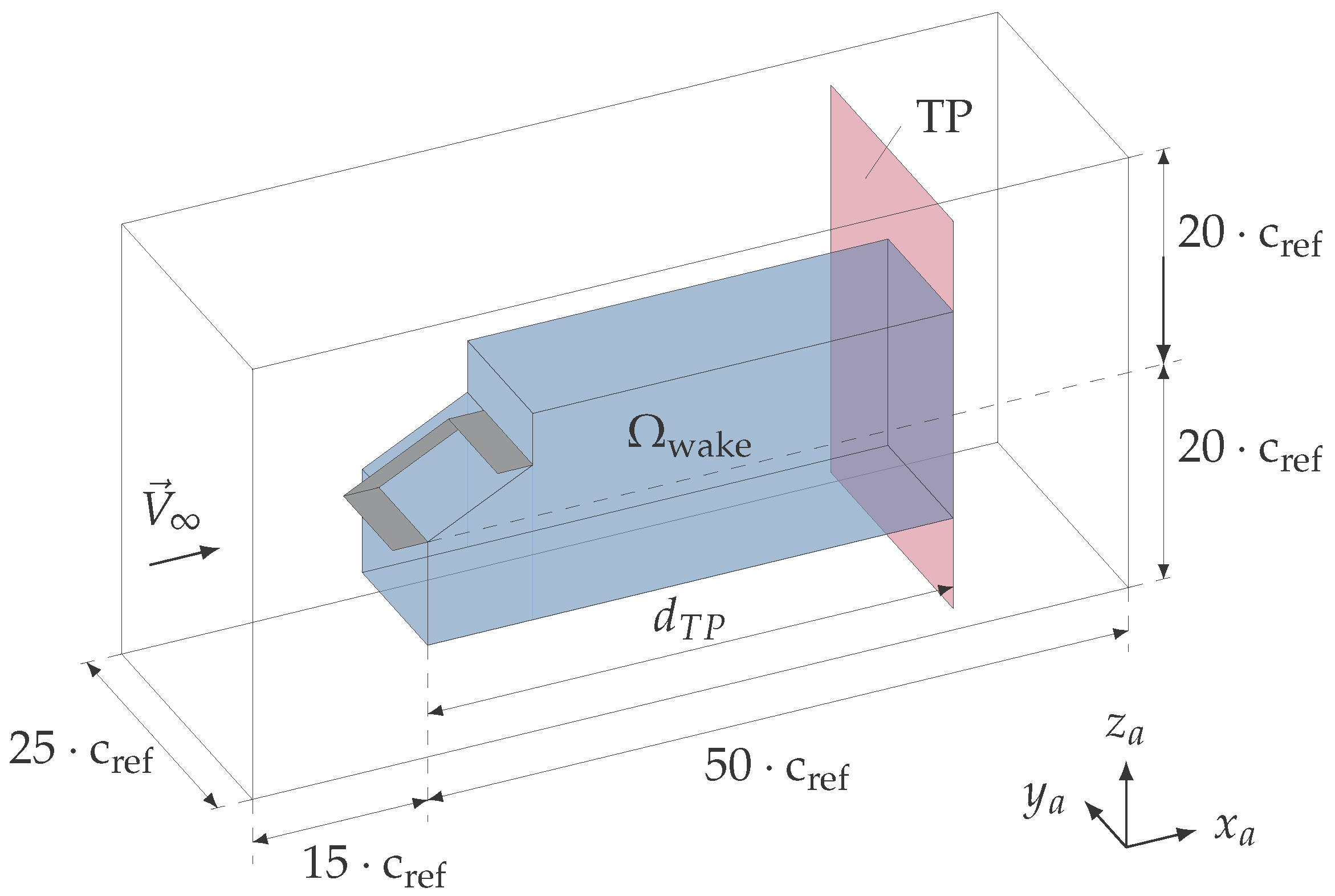
Figure 3.
Spanwise load distributions at a freestream angle of attack of .

Figure 4.
Computed span efficiency factor versus the freestream angle of attack .

Figure 5.
Wake trace location.

Figure 6.
Wake trace comparison for a freestream angle of attack of .
© 2018 by the authors. Licensee MDPI, Basel, Switzerland. This article is an open access article distributed under the terms and conditions of the Creative Commons Attribution (CC BY) license (http://creativecommons.org/licenses/by/4.0/).
Share and Cite
MDPI and ACS Style
Schirra, J.; Bissonnette, W.; Bramesfeld, G. Wake-Model Effects on Induced Drag Prediction of Staggered Boxwings. Aerospace 2018, 5, 14. https://doi.org/10.3390/aerospace5010014
AMA Style
Schirra J, Bissonnette W, Bramesfeld G. Wake-Model Effects on Induced Drag Prediction of Staggered Boxwings. Aerospace. 2018; 5(1):14. https://doi.org/10.3390/aerospace5010014
Chicago/Turabian StyleSchirra, Julian, William Bissonnette, and Götz Bramesfeld. 2018. "Wake-Model Effects on Induced Drag Prediction of Staggered Boxwings" Aerospace 5, no. 1: 14. https://doi.org/10.3390/aerospace5010014
Note that from the first issue of 2016, this journal uses article numbers instead of page numbers. See further details here.