Fully-Deterministic Execution of IEC-61499 Models for Distributed Avionics Applications

School of Science and Engineering, Teesside University, Middlesbrough TS1 3BX, UK
Aerospace 2018, 5(1), 15; https://doi.org/10.3390/aerospace5010015
Submission received: 31 October 2017
/
Revised: 28 December 2017
/
Accepted: 22 January 2018
/
Published: 3 February 2018
(This article belongs to the Special Issue Challenges in Reliability Analysis of Aerospace Electronics)
Abstract
:The development of time-critical Distributed Avionics Applications (DAAs) pushes beyond the limit of existing modeling methodologies to design dependable systems. Aerospace and industrial automation entail high-integrity applications where execution time is essential for dependability. This tempts us to use modeling technologies from one domain in another. The challenge is to demonstrate that they can be effectively used across domains whilst assuring temporally dependable applications. This paper shows that an IEC61499-modeled DAA can satisfy temporal dependability requirements as to end-to-end flow latency when it is properly scheduled and realized in a fully deterministic avionics platform that entails Integrated Modular Avionics (IMA) computation along with Time-Triggered Protocol (TTP) communication. Outcomes from the execution design of an IEC61499-based DAA model for an IMA-TTP platform are used to check runtime correctness through DAA control stability. IEC 61499 is a modeling standard for industrial automation, and it is meant to facilitate distribution and reconfiguration of applications. The DAA case study is a Distributed Fluid Control System (DFCS) for the Airbus-A380 fuel system. Latency analysis results from timing metrics as well as closed-loop control simulation results are presented. Experimental outcomes suggest that an IEC61499-based DFCS model can achieve desired runtime latency for temporal dependability when executed in an IMA-TTP platform. Concluding remarks and future research direction are also discussed.
1. Introduction
Avionics systems have undergone transformations since first aircraft have flown. They have gone through changes due to technological innovations to provide airborne capabilities (mostly required for aircraft management). The updates include typical avionics equipment for communication, navigation, and surveillance systems and technologies for vehicle systems such as flight control systems, fuel systems, and hydraulic systems. This continuous improvement and modernization brings along an inexorable evolution of the avionics architecture. The evolutionary process of architectural avionics approaches goes from former centralized and analogue solutions to latter decentralized and digital ones [1]. The latter involve networked computers and entail distributed, federated, and integrated avionics architectures. They are more lightweight (reduction of wiring) and efficient (reduction of power consumption) than former solutions whilst providing higher performance (although they are more complex and expensive). They also facilitate the realization (implementation and integration) of Distributed Avionics Applications (DAAs), mainly favoring systems dependability due to the fault tolerance provided by the distribution of functionalities.
Integrated Modular Avionics (IMA) is the latest generation of avionics architectures fostered by the aviation industry [1]. The ultimate purpose of IMA is the standardization of the onboard processing computers, so all the avionics software applications use and share the same electronic hardware platform (applications are developed for specific partitions or virtual processors). This makes scalability and reusability for further system expansions and assurance of safety-critical requirements along with Real-Time (RT) performance for certification easy [2]. Additionally, the computing and networking nature of the IMA technology allows for deployment of DAAs. DAAs make good use of the IMA architecture by deploying their functionalities along networked computers and interconnecting them to build the entire DAA. DAAs usually involve embedded RT paradigms for control and guidance. Computation and communication time is critical in DAAs since failing to meet operation deadlines may have catastrophic consequences. This manifests the tight relation between timing and dependability (temporal correctness in addition to logical correctness). Some examples of DAAs are autopilot systems, the Traffic Alert and Collision Avoidance System (TCAS), flight management systems, and the fuel measurement and management systems.
The development of time-critical DAAs pushes to the limit and beyond existing engineering methodologies and tools (particularly, modeling languages for distributed deployment and execution of modelled DAAs) to design dependable avionics systems [3]. The same challenging situations can be found in other domains such as in industrial automation, where distributed RT applications also face temporal dependability requirements. Aerospace and automation have a long history of working separately. On the one hand, this makes sense, since the technological culture to approach systems development (e.g., control software engineering practice) differs from one domain to another. Software applications are typically co-developed along with hardware platforms in aerospace, whilst they are usually developed after the factory machinery is installed in the shop-floor (in industrial automation). On the other hand, both domains entail high-integrity applications where execution time is essential for dependability. This similarity tempts us to use modeling technologies from aerospace in industrial automation and vice versa. The challenge is to demonstrate that such technologies can be effectively used across domains whilst assuring development of temporally dependable applications.
The IEC-61499 standard [4] for industrial automation is an attractive candidate to model DAAs. It is a graphical modeling language that encapsulates functionality in Function Blocks (FBs) to be deployed in networked devices for low-level control (usually RT control). FBs are building blocks (hardware-like software components) for the representation of distributed control systems (a network of FBs). Their interface entails events and data as the inputs and outputs for the FBs. Events trigger internal FB algorithms that process external/internal data. The standard is meant to enable reusability and portability of wrapped functionalities (the FBs) and distribution and reconfiguration of applications.
The research discussed in this paper involves the execution design of a DAA. The DAA model is based on the IEC-61499 standard. The research objective is to demonstrate simply that the IEC61499-modeled DAA can satisfy temporal dependability requirements as to end-to-end flow latency when it is realized in a deterministic avionics platform. The standard is fairly questioned for the lack of notation for execution time (determinism). However, the execution of the DAA model is studied when it is deployed and executed in a fully time-driven platform: time-partitioned computation and time-triggered communication. The former is provided by the IMA architecture, and the latter is provided by the Time-Triggered Protocol (TTP) [5]. The combination of these two technologies allows for fully-synchronous execution of the DAA since it provides temporally deterministic DAA behavior to guarantee predictive timing performance. The event-driven DAA FBs are synchronously executed (time-driven and enabled by events) in the IMA partitions, and FB events are transmitted over a TTP-based network. Execution design of an IEC61499-based DAA model running in an IMA-TTP platform is carried out to provide insights on the control stability of the DAA by checking effectiveness of the design in terms of execution time. Thus, closed-loop control simulation results are presented.
This paper presents an application example of the IEC-61499 standard for a DAA. The case study is a distributed fluid control system for the Airbus-A380 fuel system. Dependable fuel management is crucial for safe aircraft operation [6]. One of the key design aspects for the above system to reach safety and ultimately dependability is to have temporally-deterministic performance. Hence, reliable timing for computation of the fuel levels as well as communication between sensors/effectors and controllers is vital to achieve time-related determinism and guarantee low end-to-end latency for runtime correctness [7]. This latency depends on the scheduling of tasks in the control computer (computation) and packets in the TTP network (communication). Therefore, timing metrics are applied to the DAA scheduling to realize about the above latency (including worst/best-case latencies). In fact, latency analysis results from end-to-end latency metrics are presented.
The paper is organized as follows. Section 2 presents the research background by recapping technological aspects about the IMA architecture, the TTP paradigm, and the IEC-61499 standard and existing initiatives to integrate them with each other. Section 3 describes basic but relevant details of the fuel system of Airbus A380-800 considered by the case study. Section 4 shows details (four representation levels) of the IEC-61499 modeling of the DAA for the FMMS platform. Section 5 discusses the execution design and latency analysis approaches along with results from timing metrics (based on the DAA scheduling). Section 6 presents the modeling and simulation of the DAA control loop and a study the impact of the end-to-end latency (due to the DAA execution) on the stability of such a loop. Section 7 discusses the experimental results obtained and compares the IEC-61499 standard with other modeling approaches for DAAs. Section 8 presents conclusions and future research directions.
2. Technological Background
This section reviews three relevant technologies for the platform and application used in this paper and existing initiatives to integrate them with each other.
2.1. Integrated Modular Avionics
IMA is a computation platform that has been developed as a standard for avionics applications to facilitate the integration of hardware and software systems. Its architecture is meant to combine the benefits from a centralized computer organization with a decentralized one. IMA has processing units (modules) logically divided into virtual processors (aka partitions). These modules can exchange data with shared inputs/outputs modules as well as other processing modules. Module partitions can exchange data with other partitions (from a same module or a different one).
From a hardware viewpoint, IMA is a collection of physical modules located in a rack or cabinet. This concept can be seen in other domains such as industrial automation (backplane-based modular controllers). From a software viewpoint, IMA provides execution independence for software applications by means of isolated and dedicated partitions from a RT Operating System (RTOS) [8] that complies with the ARINC-653 standard [9] for aviation.
Time partitioning and RT execution of IMA partitions guarantee meeting synchronization constraints in time-critical avionics applications. Time RTOS partitioning provides a deterministic scheduling mechanism to assure partitions are predictively executed and switched from a partition context to another. Minor frame is the time slot for execution of each RTOS partition, and major frame is the time slot for execution of a set of RTOS partitions. Figure 1 shows the concept of the IMA architecture along with some examples of connections between modules/partitions.
2.2. Time-Triggered Protocol
The TTP [5] is a communication platform that has been mainly developed to provide determinism (along with a fault-tolerant mechanism) when transmitting data packets. It is fast and helps predict the moment (not an exact time but a time slot) in which data are sent out to the network and are received by the network’s nodes. Its off-line scheduling mechanism and fault-tolerant capability make the TTP a great candidate for time-critical DAAs. The TTP communication platform complies with the SAE AS6003 [10] for aerospace systems.
Time partitioning in the TTP is dictated by the Time-Division Multiple Access (TDMA) strategy. TTP nodes are allowed to send out messages only one time (one at a time) in each TDMA round (set of node slots). TDMA rounds are periodic and there is no chance of collision of outgoing messages in the TDMA round due to the time separation between senders.
Figure 2 shows the concept of time-driven communication provided by the TTP.
2.3. IEC 61499 Standard
The IEC 61499 standard [4] has been developed to model distributed control applications in industrial automation [11]. The standard is able to model the above applications by encapsulating and interconnecting functionalities wrapped in hardware-like software blocks or Function Blocks (FBs). The combination of encapsulated functionalities is to build up the representation of the IEC-61499 application under development. IEC 61499 follows the software engineering paradigm of component orientation whilst keeping properties of object-oriented architectures. IEC-61499 applications are deployed in resources from devices.
Figure 3 shows the application-device-resource-FB encapsulation method of the IEC-61499 standard. Clockwise from top-left to bottom-left, applications can be deployed in one or more devices (application view). On the top, devices are connected with each other through a network, and linked with the process under control (bottom). Devices (e.g., control computers or instruments) can have one or more resources that are able to contain deployed FBs. FBs are for computation and communication. Computation FBs are classified as basic FBs, composite FBs, and sub-application FBs. Communication FBs are generally categorized as requester and responder FBs.
2.4. Related Work
The IEC-61499 standard has long been used to develop control applications of Distributed Time-Critical Systems (DTCSs) in industrial automation. Early considerations of the IEC-61499 standard for avionics include DTCSs such as an aircraft fuel management system [12,13]. A later discussion on the use of the above modelling standard from industrial automation for aerospace has also been presented by the author of this paper [3].
The research presented in this paper combines three technologies: IMA, TTP, and IEC 61499. Even though the IMA and TTP technologies are from about two decades ago, there are not many approaches that integrate them or discussions on their combination. This is in great part because IMA comes along the Avionics Full Duplex (ADFX) communication platform. However, existing approaches include a network performance analysis [14], platform modelling based on Time-Triggered Constraint-Based Calculus (TTCC) [15,16], a scheduling algorithm for distributed IMA based on a network partition integrating model [17], a cost optimization strategy for iterative integration of IMA and Time-Triggered Ethernet (TTEthernet) multi-critical functions [18], embedded cloud computing for critical systems [19,20], and PhD dissertations about integrated task and message scheduling for time-triggered aerospace systems [21] and mixed-criticality in distributed real-time systems [22].
Publications of research works on the combination of TTP with IEC61499 are few, and they naturally come from industrial automation. An effort has been made to evaluate communication protocols for distributed RT control systems in industrial automation developed by the IEC-61499 standard [23]. This effort evaluates industrial networks such the Controller Area Network (CAN) and its variations, including Time-Triggered CAN (an implementation of the TTP). Also, a formal model for distributed IEC61499-based systems has been proposed. Such a research contribution aims at providing a locally synchronous execution platform (no network involved) for FBs and recommends TTPs for globally synchronous execution [24] in order to reach fully synchronicity (local and global time partitioning). Another approach proposes a time-stamped event-based solution for execution semantics of IEC-61499 FBs of industrial cyber-physical systems considers time-triggered and event-triggered mechanism for the execution platform [25]. The semantic approach aims to comply with deterministic RT requirements of the above systems.
The situation in term of publications is even worse for the combination of IMA with IEC 61499. There have been very few publications on this subject so far. Whilst the idea of using the IEC 61499 standard in aerospace avionics is not novel [12,13], as discussed at the beginning of this subsection, the first published intent to combine the IMA platform with the deployment of IEC-61499 applications comes from recent years [3]. The combining proposal makes a point on the demand of innovative engineering methods and tools to analyze/notate requirements for DTCSs. Modeling languages play a key role in the design process of DTCSs, and the IEC 61499 standard is an attractive modeling methodology for DTCSs. The proposal also presents a discussion on issues related the IEC 61499 standard as a potential tool for aerospace systems.
The scheduling problem in time-partitioned avionics systems is gaining interest in the aerospace community. Following this direction, different approaches have been proposed to deal with the scheduling of time-driven tasks and messages. A scheduling algorithm (synchronized highest level first) along with two rescheduling and backtracking procedures (release time deferment and backtracking and priority promotion) have been proposed [26]. The algorithm is meant to schedule periodic applications (task graphs) that involve periodic and aperiodic tasks and messages from safety-critical time-triggered avionics systems. Other scheduling approach makes use of model checking techniques to compute schedules with RT requirements for optimal solutions and reduction of end-to-end latency [21].
3. Case Study
This section presents basic but relevant details of the fuel system of Airbus A380-800 [6] considered by the case study.
3.1. Aircraft Fuel Rig
The Airbus A380-800 fuel rig entails mechanical and electromechanical components such as tanks, pipes, valves, pumps, and sensors. The fuel storage is located in the wings by means of several fuel tanks arranged one after the other and interconnected to make fuel transfers possible. The rig main operations are refueling/defueling, engine supply, fuel transfer, and fuel jettison. It also provides fuel to the Auxiliary Power Unit (APU) and Hydraulic System Cooling (HSC). The rig functionality is very sophisticated and critical for a safe aircraft operation. Thus, dependability is particularly essential for temporal actions of valves and pumps to carry out the above operations.
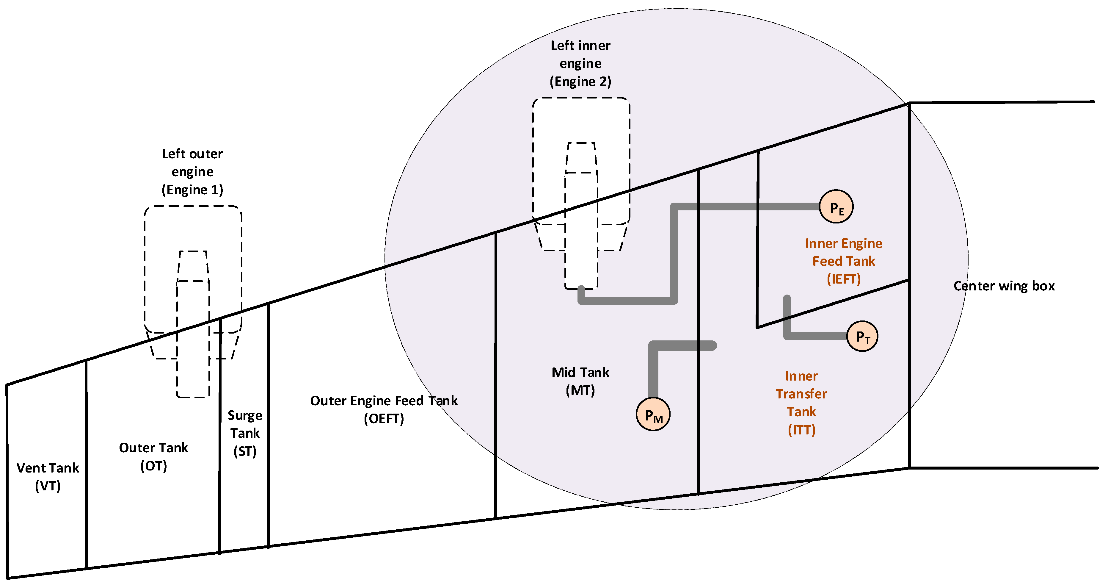
The fuel rig system has eleven fuel tanks along with three vent tanks and two surge tanks. They are configured in three isolated sets of tanks located in (1) the left wing, (2) the right wing, and (3) the horizontal stabilizer. Each of the wings has five fuel tanks, a surge tank, and a vent tank. The five tanks are an Outer Tank (OT) with a capacity of about 10,448 L, an Outer Engine Feed Tank (OEFT) with a capacity of about 27,634 L, a Mid Tank (MT) with a capacity of about 36,453 L, an Inner Transfer Tank (ITT) with a capacity of about 46,144 L, and an Inner Engine Feed Tank (IEFT) with a capacity of about 29,374 L. The horizontal stabilizer has a trim tank and a vent/surge tank. Figure 4 shows the configuration of tanks for the left wing and the specific part of the fuel tank system that is considered in the case study.
The case study scenario considers fuel transfer and supply operations in the left wing. There are two fuel transfers: one from the MT to the ITT and the other from the ITT to IEFT. The engine supply operation is to provide left inner engine 2 with fuel during fuel burn sequencing (aircraft operation). The fuel is steadily transferred from the MT to the ITT as well as from the ITT to IEFT during normal aircraft operation. The IEFT must be as full as possible at all times to avoid starvation and guarantee best feeding to engine 2.
3.2. Fuel Measurement and Management Platform
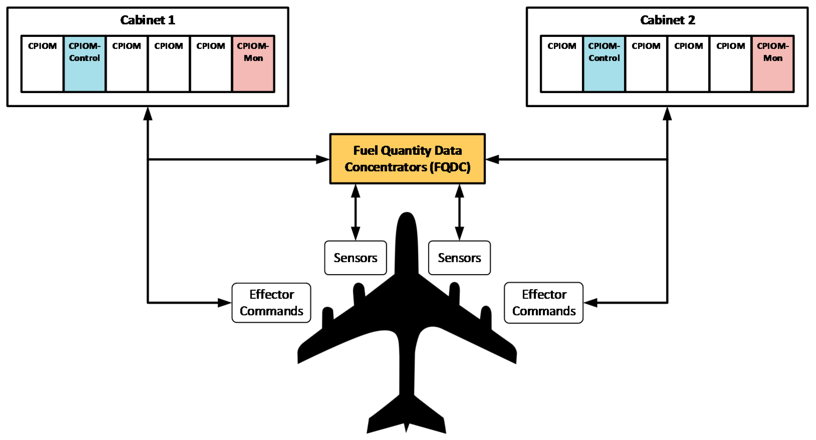
The Airbus A380-800 fuel rig has a Fuel Measurement and Management System (FMMS). The FMMS has an electronic hardware platform that is based on IMA computation and Avionics Full DupleX (AFDX) communication. The case study considers a platform based on IMA, although the communication between IMA Central Processor Input/Output Modules (CPIOMs) is assumed to be carried out by means of the TTP. The arrangement of the CPIOMs is in pairs: a command CPIOM for fuel management and a monitoring CPIOM for fuel measurement.
The CPIOMs are interconnected with each other, the Fuel Quantity Data Concentrators (FQDCs), and the Integrated Refuel Panel (IRP). The FQDCs are data acquisition units to compute fuel quantity data and get feedback from effector signals (Figure 5). The FQDCs are originally connected to the CPIOM via ARINC 429 and are not an IMA module (CPIOM). The avionics configuration of the above FMMS is twin for redundancy. However, the case study considers no redundancy and that the FQDC is included in the CPIOM and connected via TTP (instead of ARINC 429).
Effectors and sensors connected with each other through embedded computers (IMA) and a network (TTP) close the control loop. This link defines the end-to-end latency that is relevant to the fuel control application discussed in this paper.
4. Distributed Fuel Control Application
This section shows details of the IEC-61499 modeling of the DAA for the FMMS platform, including the four representation levels as discussed in Section 2.3.
4.1. IEC-61499 Application View
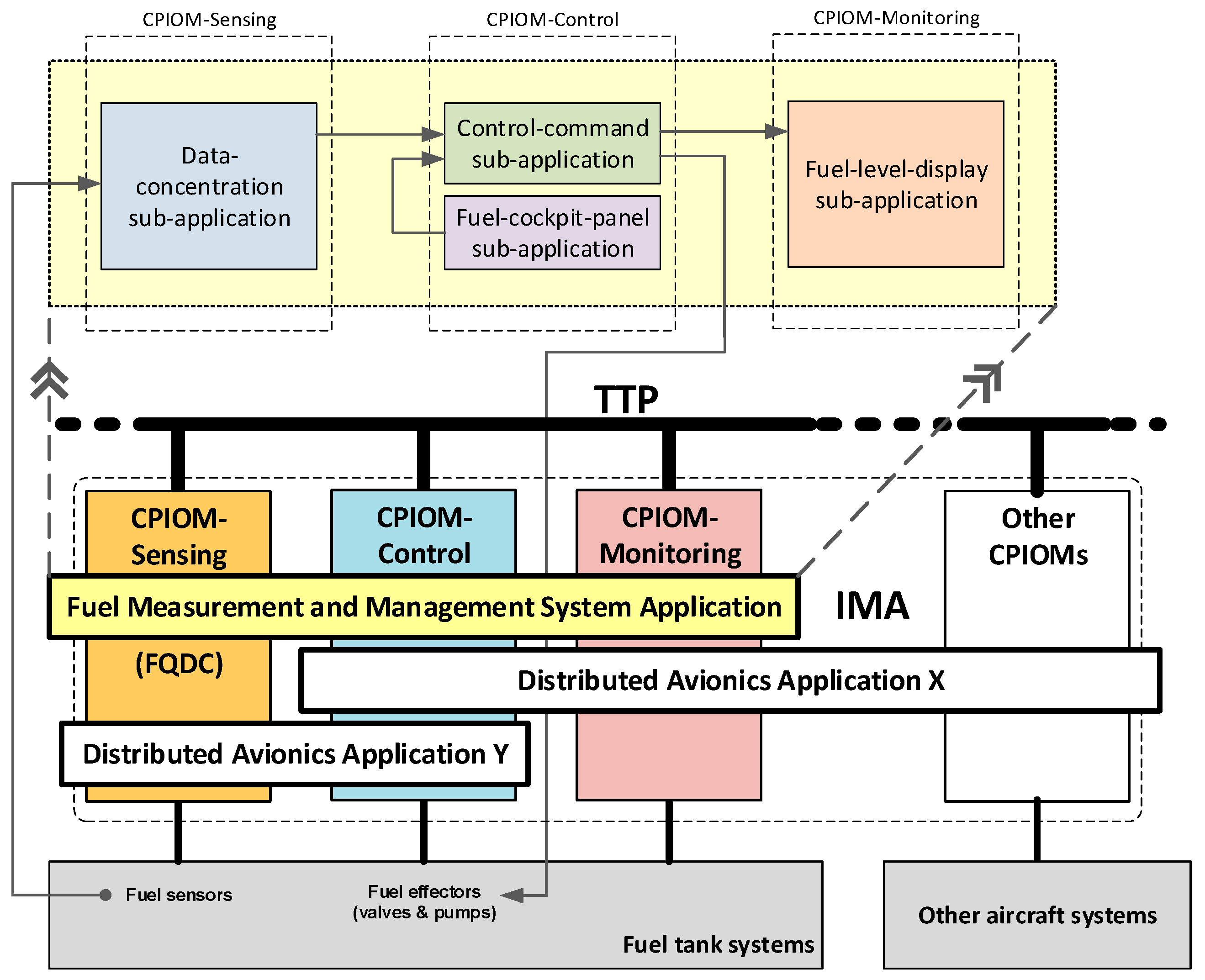
The FMMS platform executes a control software application deployed across the controlling and monitoring CPIOMs. This DAA is modelled by the IEC-61499 standard. It was modelled by means of the Function Block Development Kit (FBDK) [27], and experimental results are available in an earlier publication [3]. The IEC61499-compliant DAA model is divided into the following sub-applications: control command, fuel cockpit panel, fuel level display, and data sensing concentration. It is deployed in three different IEC-61499 devices (as each CPIOM is modelled): (1) a CPIOM-Control, (2) a CPIOM-Monitor, and (3) a CPIOM-Acquisition, i.e., the Fuel Quantity Data Concentrator (FQDC). Figure 6 shows how the FMMS DAA is distributed over the CPIOMs. The full FMMS DAA and its FBs (without the interface service FBs) are shown in Appendix A.
The IEC61499-compliant FMMS devices host different pieces of the DAA, i.e., sub-applications deployed in device’s resources. The control-command sub-application and the fuel-cockpit-panel sub-application are deployed in CPIOM-Control. The fuel-level-display sub-application is deployed in the CPIOM-Monitor. The sensing-concentration sub-application is deployed in the CPIOM-Acquisition.
Sub-applications are built of interconnected FBs that provide specific functions to the whole DAA functionality. FBs from different resources (partitions) or devices (CPIOMs) communicate with each other by means of a publisher-subscriber mechanism (service FBs). FBs within the same resource are directly interconnected (no SFBs are required). The FBs from each sub-application are presented in Appendix B.
The case study focus is on the ITT control. This entails the following functionalities: pilot interface, ITT sensing, mid pump control, and fuel gauging. Thus, functionalities (FBs) related to the ITT are considered for simplification of the case study. However, this does not invalidate the demonstration of fully-deterministic execution for FBs. Two scenarios are investigated to analyze the DAA performance. DAA sub-applications are deployed in only one resource per device in scenario 1. There is a similar deployment situation for the DAA sub-applications (in scenario 2) except for the control-command and fuel-cockpit-panel sub-applications, which are deployed in different resources (partitions) from CPIOM-Control (device). Hence, the control-command sub-application is distributed in two different resources (within the CPIOM-Control device), and the fuel-cockpit-panel sub-application is deployed in a third resource of the CPIOM-Control device in scenario 2.
4.2. IEC-61499 Device View
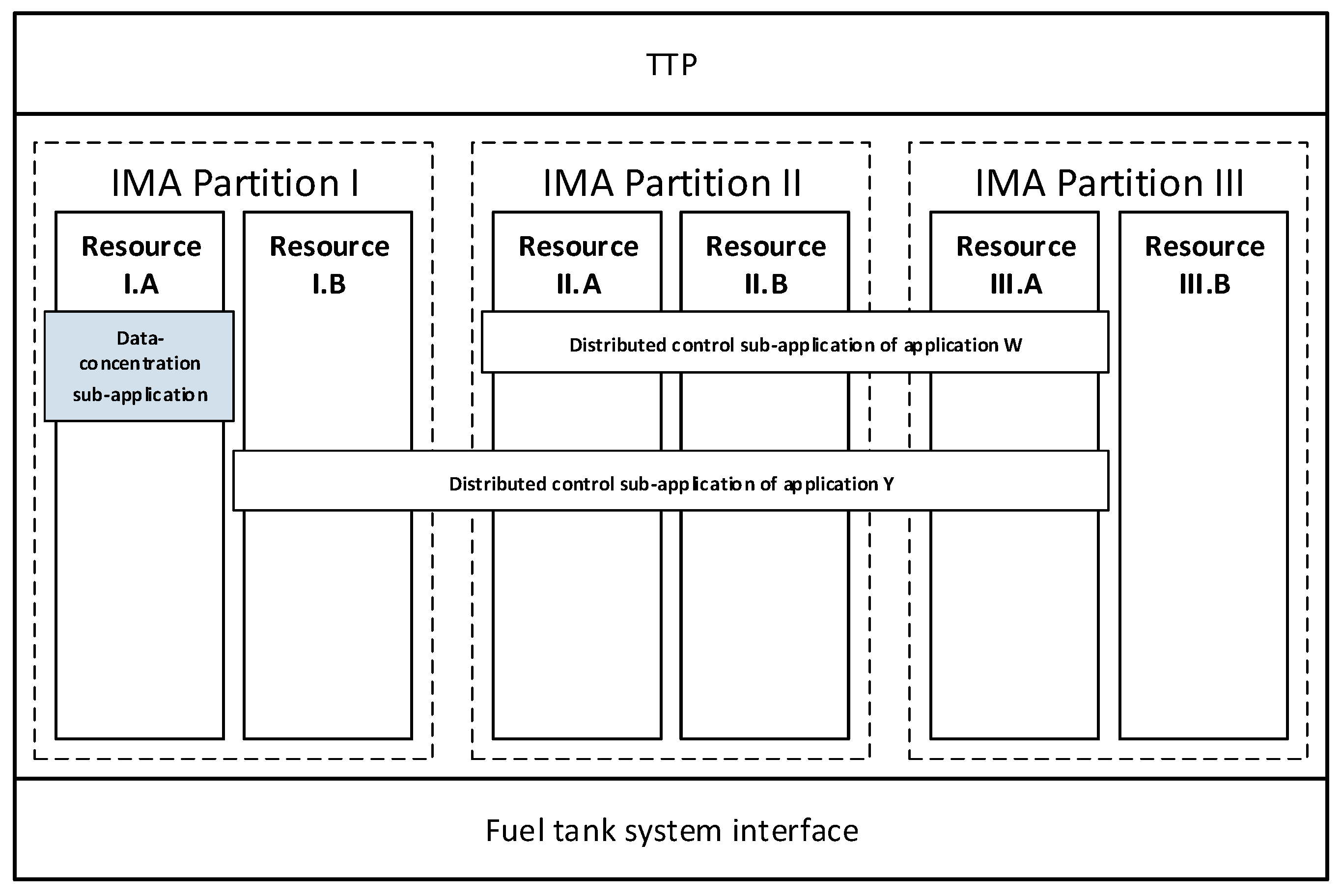
Figure 7 shows the CPIOM-Sensing device along with its resources and how the sub-applications are deployed in resources. Each IMA partition entails two resources. The data-concentration sub-application is only deployed in resource I.A for scenario 1 and 2. CPIOM-Sensing device can also deploy other DAAs such as the distributed control application W and Y.
Figure 8 shows the CPIOM-Control device along with its resources and how the sub-applications are deployed in resources. Each IMA partition entails two resources. The fuel-cockpit-panel sub-application is only deployed in resource I.A, and the control-command sub-application is only deployed in resource I.B of partition I in scenario 1. The fuel-cockpit-panel sub-application is only deployed in resource I.A, and the control-command sub-application is deployed in resource I.B (partition I), resource II.B (partition II), and resource III.A (partition III) in scenario 2. CPIOM-Control device can also deploy other DAAs such as the distributed control application X, Y, and Z.
Figure 9 shows the CPIOM-Monitoring device along with its resources and how the sub-applications are deployed in resources. Each IMA partition entails two resources. The fuel-level-display sub-application is only deployed in resource I.A (partition I) in scenario 1, and it is deployed in resource I.A (partition III) in scenario 2. CPIOM-Sensing device can also deploy other DAAs such as the distributed control application Y and Z.
4.3. IEC-61499 Resource View
Table 1 shows the deployment of FBs from the sub-applications for scenario 1, and Table 2 shows the deployment of FBs from the sub-applications for scenario 2.
The DAA defines a distributed fuel control application where parts of it (DAA sub-applications) are distributed across device resources from the FMMS platform. Architectural details and layout of the DAA sub-applications are shown within each resource as follows.
Figure 10 shows FB details of the CPIOM-Sensing device resource I.A for scenario 1 and 2. The configuration of resource I.A is according to Table 1 and Table 2, where the data-concentration sub-application is only deployed in Partition I for both scenarios.
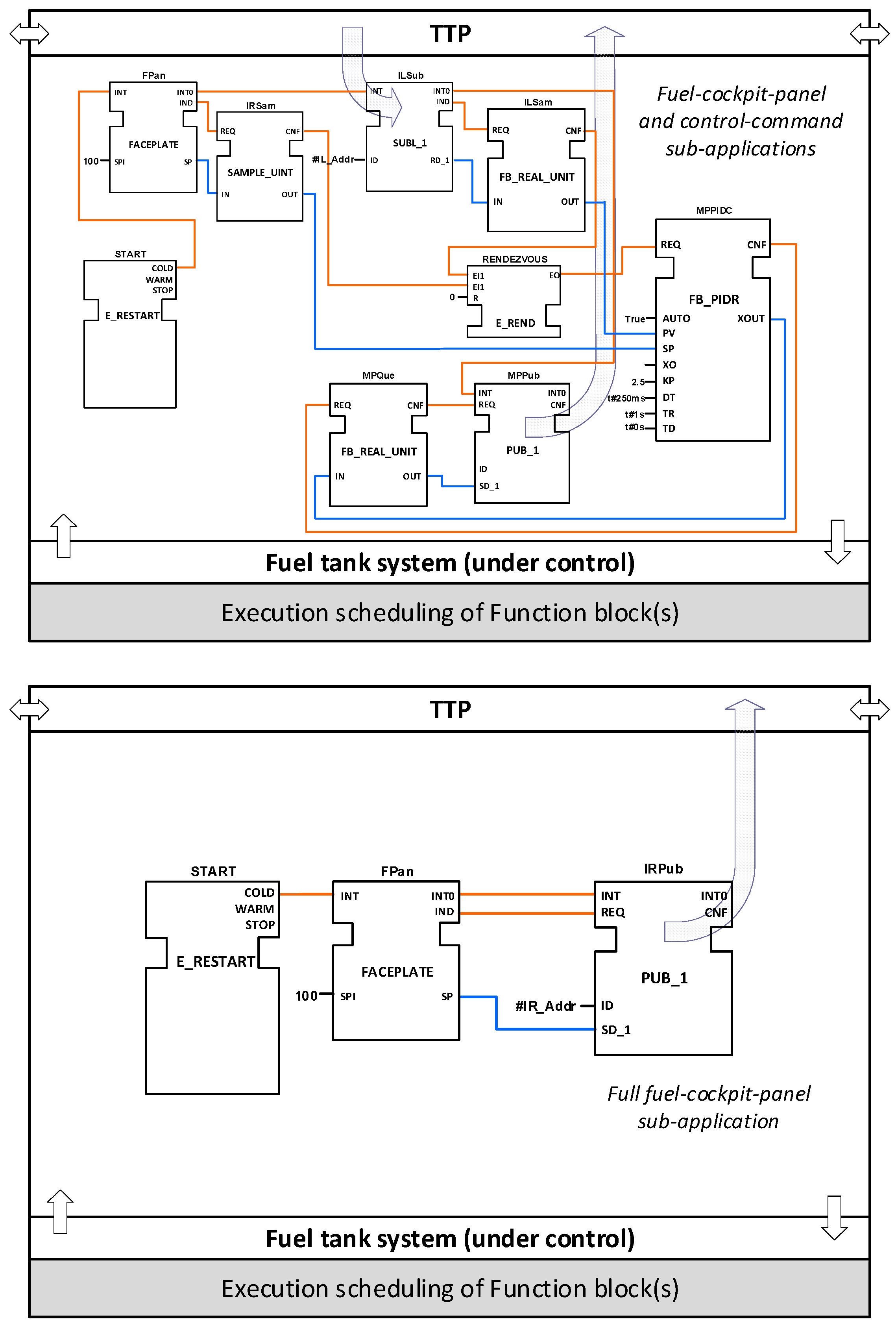
Figure 11 shows FB details of the CPIOM-Control device resource I.A for scenario 1 and 2. The configuration of resource I.A is according to Table 1, where the fuel-cockpit-panel sub-application and the control-command sub-application are both deployed in Partition I (scenario 1). The configuration of resource I.A is according to Table 2, where the fuel-cockpit-panel sub-application is only deployed in Partition I (scenario 2).
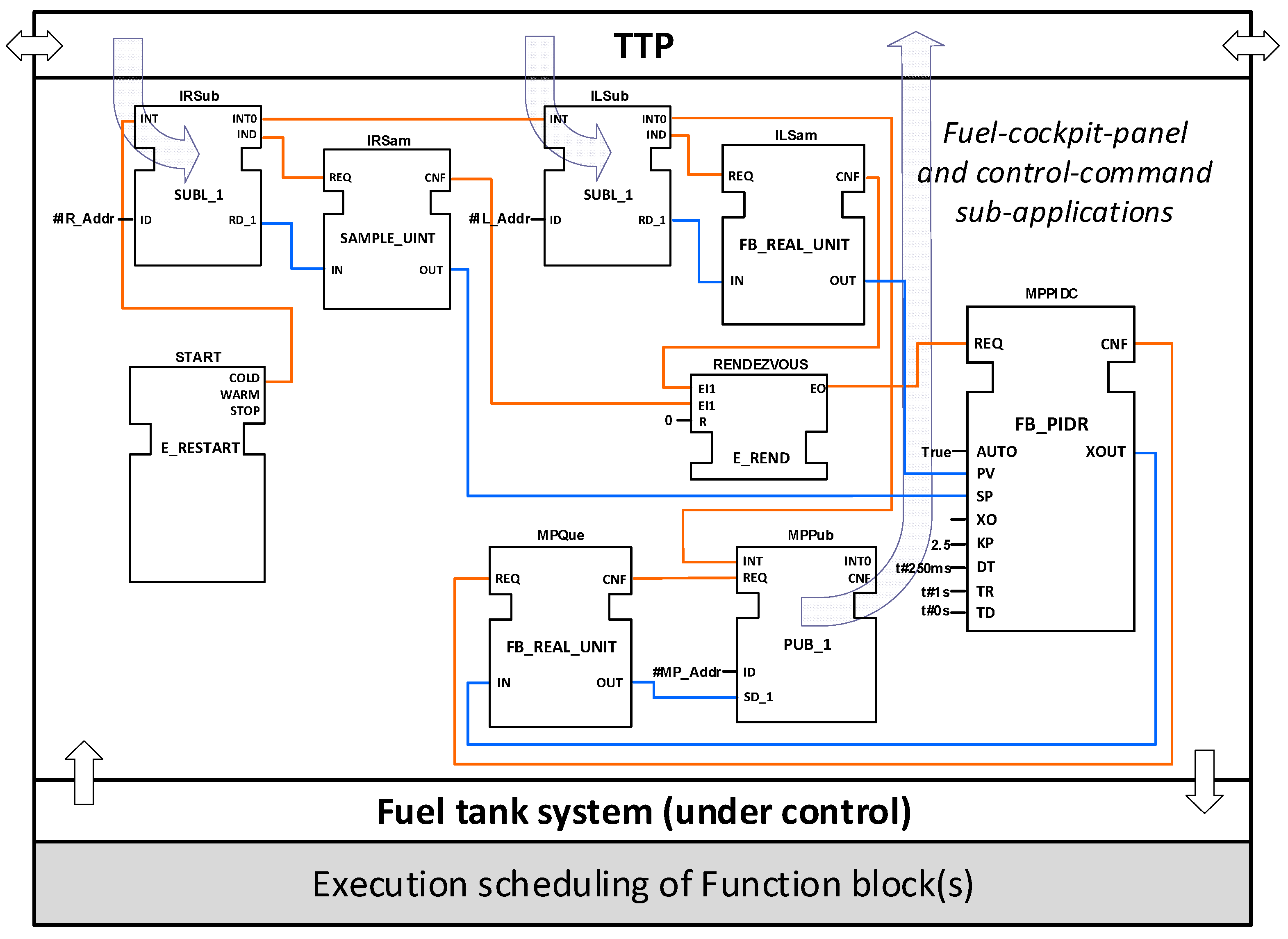
Figure 12 shows FB details of the CPIOM-Control device resource II.A for scenario 2 (there is no deployment of the control-command sub-application in this resource for scenario 1). The configuration of resource II.A is according to Table 2 where the control-command sub-application is only deployed across resource II.A (Partition II).
Figure 13 shows FB details of the CPIOM-Monitoring device resource I.A for scenario 1 and the CPIOM-Monitoring device resource III.A for scenario 2. The configuration for resource I.A is according to Table 1, and the configuration for resource III.A is according to Table 2. Both resource host the same sub-application.
5. Design and Analysis
This section discusses the execution design and latency analysis approaches along with results from timing metrics (based on the DAA scheduling).
5.1. Execution Design
The execution design method for the IEC61499-modelled DAA develops a scheduling approach for the DAA FBs. It consists of timing the execution of the above FBs in a way to guarantee the low end-to-end latency for the DAA to temporal dependability. The DAA scheduling approach is based on the execution time defined by synchronic clock ticks from the IMA-TTP platform (Section 3.2). It is for tasks and messages from the DAA under consideration. Each FB of the DAA IEC-61499 model is considered a task (periodic tasks with/without variable period) to be executed. Events and data sent from and to FBs are considered messages to be exchanged between FBs.
The FB task structure is fully defined by the FB architecture (structure and behavior). Two static scheduling policies are considered: off-line scheduling and on-line scheduling. The former keeps the execution order for FBs, and the time (FBs are executed) is well defined in advance. The latter allows for changes in the execution order of FBs, although the order is mostly sequential. It is driven by precedent tasks and fixed task priorities. Both policies are non-preemptive and make subsequent inter-task communication with flawless synchronization between FB tasks possible (including mutual exclusion for computing resources).
The executions of FBs are triggered by IMA-TTP platform ticks (every 1 ms) and enabled by FB events (which come along with FB data). Each IMA partition minor frame (RTOS partition slot) is of 10 ms. The TDMA round is 1 ms for the TTP. Both scheduling approaches (from IMA and TTP) are assumed to be synchronized so that full determinism is guaranteed at the computation and communication levels.
The duration of each FB task is no longer than the period of the IMA-TTP platform tick (1 ms). FBs are scheduled so that their execution starts at an IMA-TTP platform tick in scenario 1 (1 ms) and just after the completion of the execution of the FB antecessor in scenario 2 (synchronized execution every 100 μs). The FB task deadline is the tick period in any scenario, and it is assumed to always be met by the FBs. Details of the duration of each sub-application FB are presented in Appendix B.
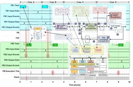
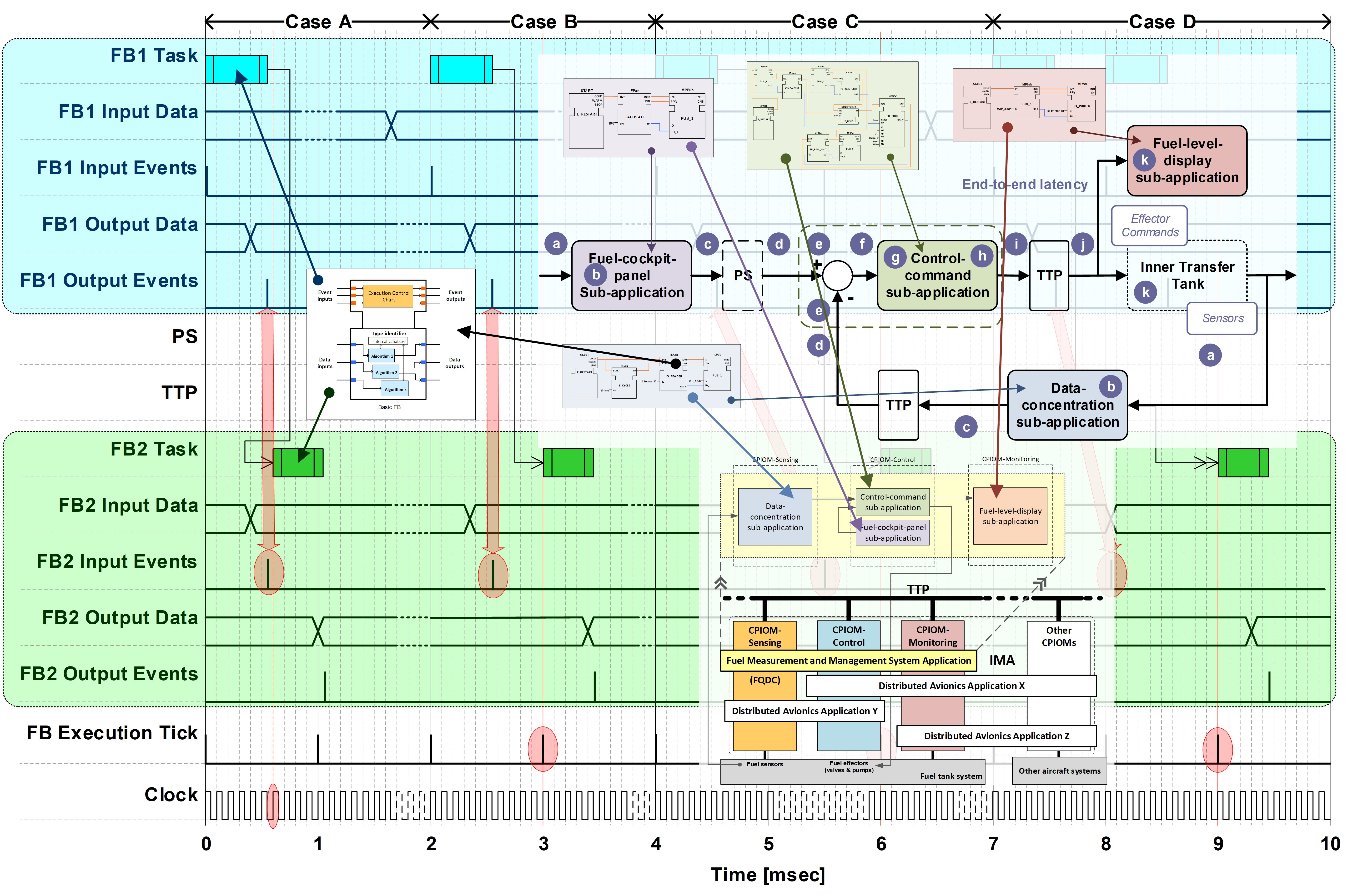
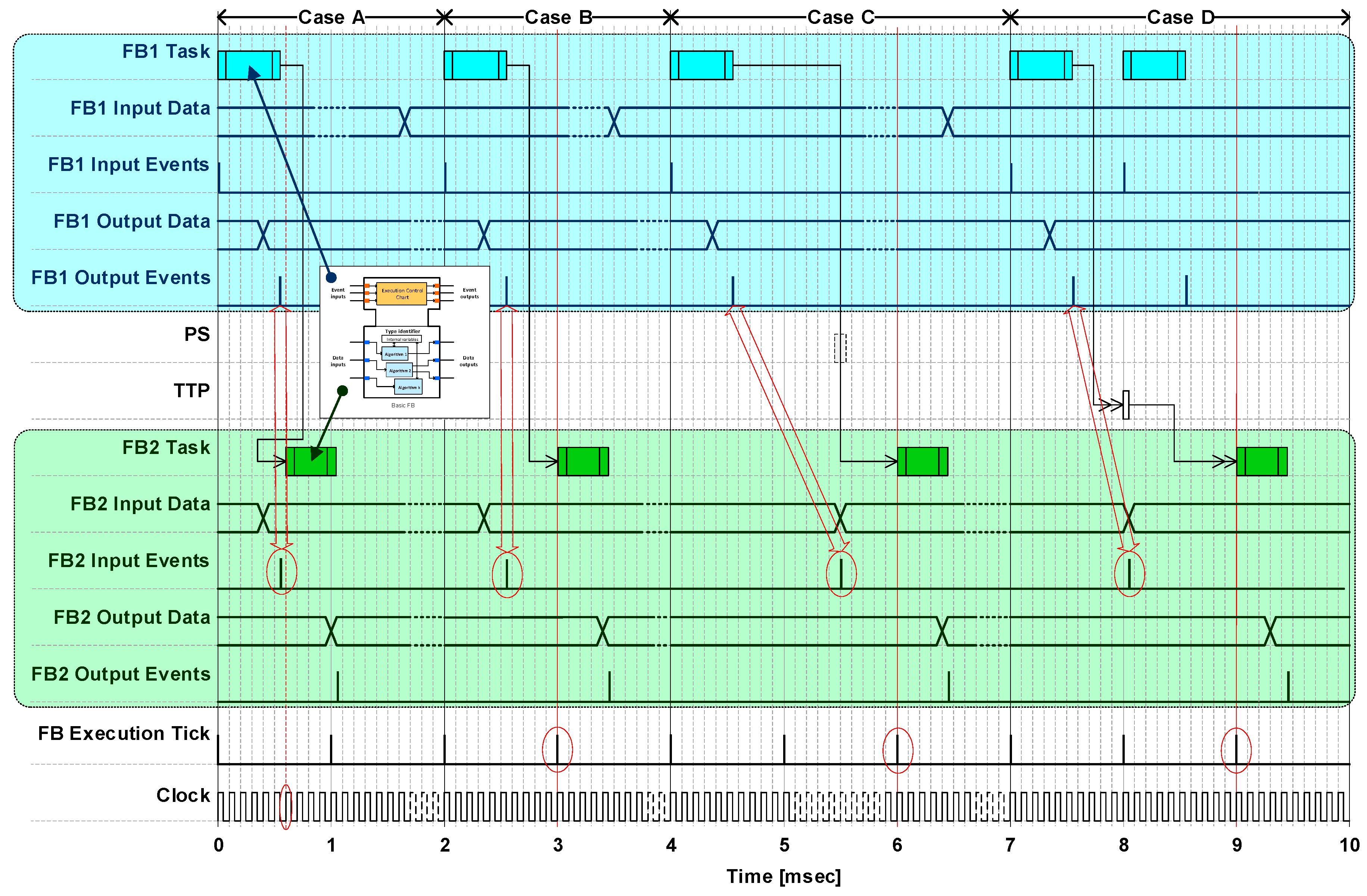
Figure 14 presents four cases of execution for two FBs (computation of and communication between FB1 and FB2 (based on the FB execution timing [28]). Case A shows an example of on-line scheduling (only one partition). FB2 is executed in the next positive clock edge as soon as FB1 finishes. Case B shows an example of off-line scheduling (only one partition). FB2 is executed in the next IMA-TTP platform execution tick edge as soon as FB1 finishes. Case C shows an example of off-line scheduling (more than one partition). FB2 is executed in the next IMA-TTP platform execution tick edge (in a different partition or even device than FB1) as soon as FB1 finishes. Case D shows an example of off-line scheduling (one or more than one partition). FB2 is executed in the next IMA-TTP platform execution tick edge (in a different device than FB1) as soon as FB1 finishes. There is also a second execution of FB1, of which the output is not considered by the FB2 execution. This situation is handled in a similar way for any scheduling case (first-come, first-served basis for events-data enablers).
5.2. Latency Analysis
The timing of the DAA scheduling defined by the execution design approach (Section 5.1) plays a key role to achieve time-related determinism. One of the relevant aspects of interest of timing is the end-to-end latency defined by time that takes the data flow to go through a path defined between the sensing elements and the effecting elements of the DAA. The timing metrics for the end-to-end latency is defined as follows:
- : end-to-end latency
- finishing time for task n ()
- : beginning time for task i ()
- total amount of tasks for the end-to-end flow considered ()
The end-to-end latency calculation in (1) is useful to analyze whether the DAA meets the temporal dependability requirements from a software-engineering viewpoint and the cross-discipline impact of such a measurement on the control-loop stability from a control-engineering viewpoint [29]. The latency analysis entails calculation of the worst-case flow latency and the best-case flow latency. They define the maximum and minimum latencies that can be expected from the execution of FBs.
The above execution design method as well as the end-to-end latency analysis are applied to the ITT control in the FMMS control software application (Section 4). They are discussed in the following subsections for off-line and on-line scheduling strategies in two scenarios.
5.3. Scenario 1
Sub-application FBs (as tasks) are sequentially and statically scheduled for the first strategic scheduling configuration in scenario 1a. Figure 15 shows how FBs from parts of the DAA sub-applications (that make possible the control of the mid pump) are scheduled. All the FBs are executed in partition I of each CPIOMs. The CPIOM partitions (minor frame) are all considered to be synchronized by means of the TTP (TDMA round). Executions of FBs are clearly separated from each other by means of execution ticks of 1 ms.
The fuel-cockpit-panel sub-application and the data-concentration sub-application are executed in different CPIOMs. Thus, their FBs can be executed at the same time (0–2 ms). The TTP messages are separated in time as they come from different CPIOMs (2–3 ms) and have assigned unique sending time slots. Equation (1) for Figure 14 is calculated as follows:
Equation (2) can be simplified since the beginning and finishing times are the same for all the FBs but MPSub. Hence, it just becomes the summation of all the FB execution periods (nine in total) plus the duration of the MPSub FB (0.2 ms as supposed). Therefore, the end-to-end latency is:
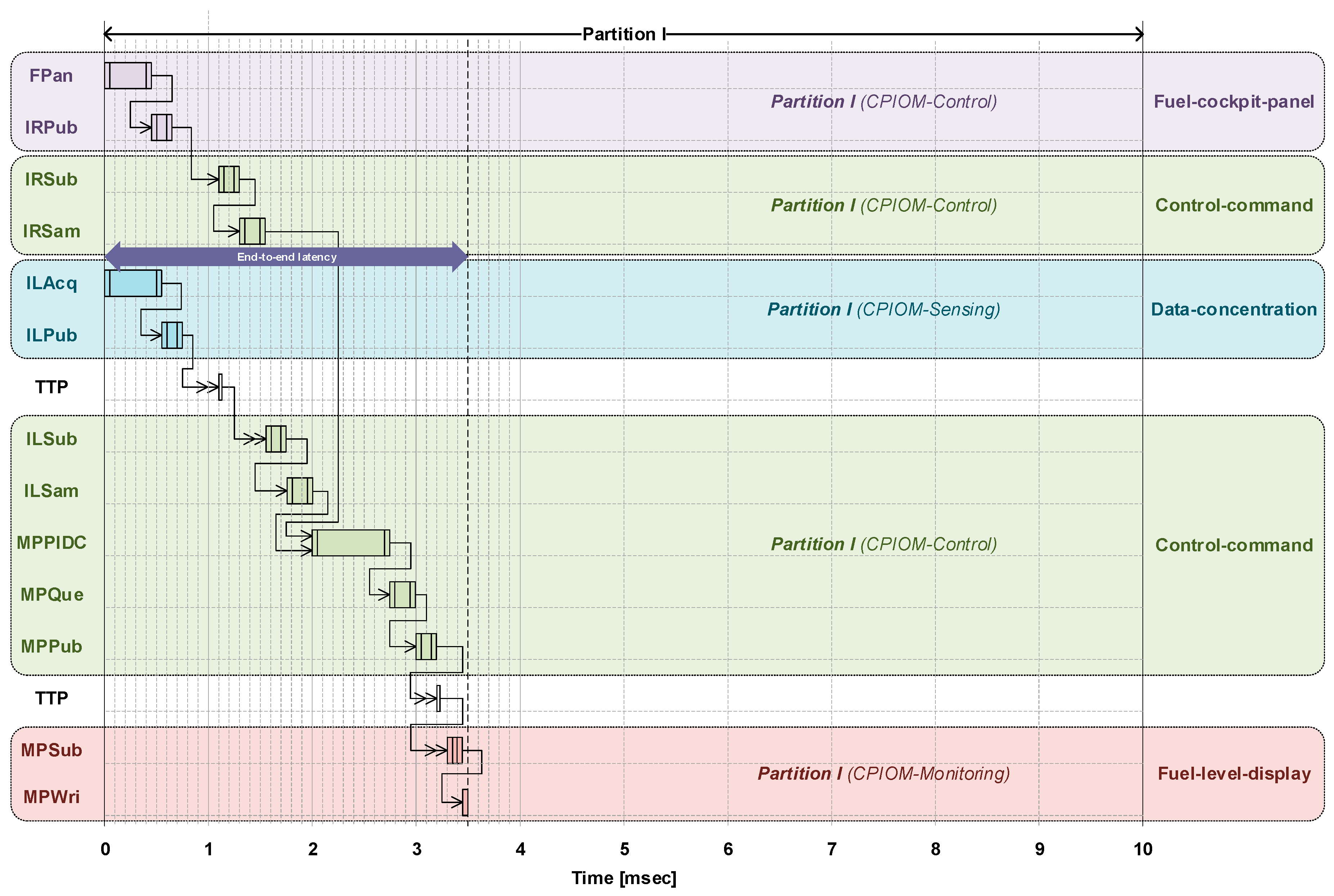
Sub-application FBs (as tasks) are sequentially and dynamically scheduled for the second strategic scheduling configuration in scenario 1b. FBs are dispatched as their required previous FB finishes its execution and the output is available. The enabler (for FB dispatch) is the event signal coming from the FB antecessor. Thus, the scheduling rules are driven by the FBs. Figure 16 shows how FBs from parts of the DAA sub-applications (that makes possible the control of the mid pump) are scheduled.
All the FBs for the control of the mid pump are now executed in a shorter time. Thus, it is expected that the end-to-end latency is smaller. However, the point of this scheduling approach is to be an alternative to the one presented above and show that an event-driven execution of the FBs can also work well by providing determinism and complying with the timing requirements. Equation (2) for Figure 15 is calculated as follows:
5.4. Scenario 2
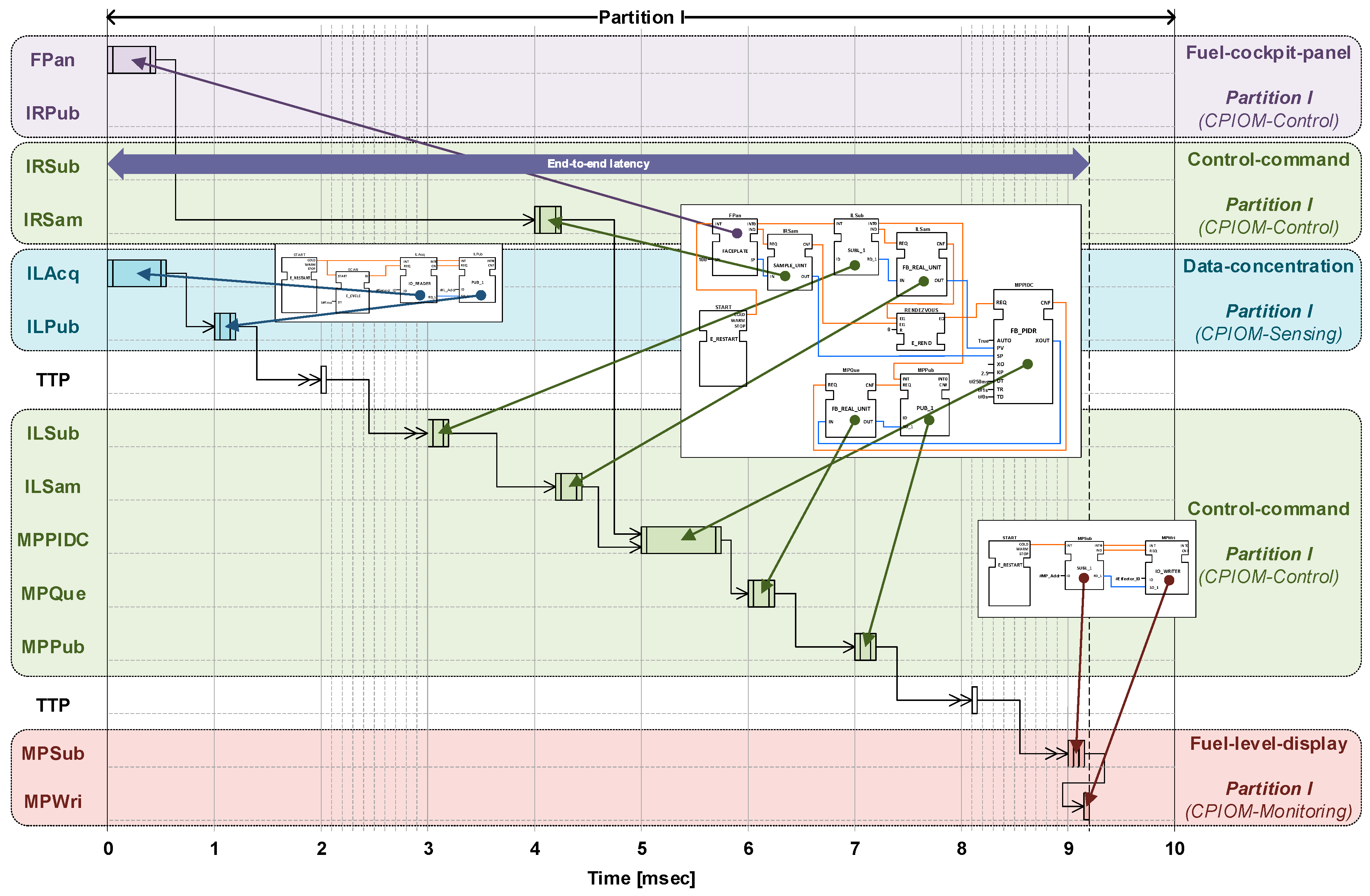
Sub-application FBs (as tasks) are sequentially and statically scheduled for the first strategic scheduling configuration in scenario 2a. Figure 17 shows how FBs from parts of the DAA sub-applications (that make possible the control of the mid pump) are scheduled.
DAA functionalities are distributed in different partitions in scenario 2a. The use of more partitions eventually makes the end-to-end latency longer due to the partition execution times. FBs are scheduled per partitions as they are shown in Figure 15.
Equation (2) can be simplified since the beginning and finishing times for FBs are overwritten by time batches defined by the IMA partitions. All the FBs but MPSub and MPWri comply with the above timing constraint. Thus, Equation (2) becomes the summation of the two partition time slots and the duration of the MPSub FB (0.2 ms as supposed). Therefore, the end-to-end latency is
Sub-application FBs (as tasks) are sequentially and dynamically scheduled for the second strategic scheduling configuration in scenario 2b. FBs are dispatch as their required previous FB finishes its execution and the output is available. The enabler (for FB dispatch) is the event signal coming from the FB antecessor. Figure 18 shows how FBs from parts of the DAA sub-applications (that make possible the control of the mid pump) are scheduled.
The scheduling of FBs follows a pattern from Figure 16 for each partition, i.e., FBs are dispatched as their antecessors finish their execution. The end-to-end latency is expected to be similar to the one provided by the scheduling approach in Figure 17. Therefore, it does make sense that Equation (2) provides the same result than in scenario 1b (scheduling strategy 1b) when FBs are dispatched as their antecessors finish their execution since the execution timing is still defined by the IMA partitions. Thus, Equation (2) for Figure 18 is
FBs (tasks) are required to be executed within the cycle (1 ms). Thus, the deployment of FBs is scheduled in a way no FB (task) finishes after the above cycle. They are meant to have a start time that meets the cycle tick. However, they are allowed to start after (not before) each tick, but they must finish just before (sooner than) the end of the cycle (deadline) to allow for communication between FBs. The above task jitter is allowed even though the IMA platform is fully reliable to meet timing. It would not be a problem if a task finishes after the cycle since executions of FBs are triggered by ticks but also enabled by events. Therefore, an FB is not executed by the tick if no input event (that invoke the FB) is present. A similar situation occurs with messages in the TTP platform. Messages consist of event and data. Node broadcast can happen at any point in the TDMA round. The TTP platform is fully reliable. However, any missing or delayed message (beyond TDMA round) will not trigger the linked FB(s), so FB execution synchronization is guaranteed.
6. Control Performance
This section presents the modeling and simulation of the DAA control loop and a study the impact of the end-to-end latency (due to the DAA execution) on the stability of such a loop.
6.1. Control Loop Model
The results from the end-to-end latency analysis for scenario 1 and 2 (Section 5.3 and Section 5.4) can be evaluated across engineering discipline (from a control-engineering viewpoint) by means of cross-checking the impact of such a latency on the DAA control loop. This is a way to verify that the latency (due to execution of FBs) does not affect the DAA performance since the DAA is temporally dependable.
The end-to-end latency is the time elapsed between sensors and effectors in a control system. It considers all the flow latencies encountered along the sensor-effector path. Figure 19 shows the end-to-end latency for the DAA sub-applications (focus on the ITT as scheduled) on a block diagram (a from control engineering viewpoint). It includes two TTP blocks and a Partition Switch (PS) block.
The table on the right of Figure 19 shows the triggering times for the tasks (execution of FBs) as scheduled by the two static scheduling strategies in the two scenarios. There is a slight different in the triggering times for b, c, d, and e for the reference signal (input of Fuel-cockpit-panel), as specified in the table below.
The end-to-end latency of the DAA execution has an impact on the control stability of the FMMS. It is expected that long end-to-end latencies make the FMMS more unstable, whilst shorter ones do not have any change in the FMMS stability (from the control viewpoint). The above latency is incorporated in the control model (block diagram) of the FMMS to investigate the impact of such a delay in the control loop. Figure 20 shows the above model for the FMMS (only ITT and IEFT control).
The model of the FMMS is a typical block diagram that consists of the system under control (Airbus A380-800 fuel rig) and its controller (Proportional-Integral-Derivative or PID controller). The PID controller was tuned to meet non-official specifications and its tuning process is out of the scope of this paper. The former is represented by two triangle-shaped blocks for the gain of the two pumps (Mid Pump and Transfer Pump), two signal summation points (circles), and two square-shaped blocks for the integrators. Additionally, there are two square-shaped blocks for the tank-level reference signals for each tank (Mid Pump Set and Transfer Pump Set points for their desired levels), a random signal generator along with a transport-delay block to simulate the behavior of the engine 2 pump, and two square-shaped blocks for each of the control loops (the top one is for the mid pump and the bottom one is for the transfer pump) to specify the latency introduced by part of the DAA execution. The controller is included in the command sub-application.
6.2. Control Stability Analysis
The FMMS stability can be analyzed in the frequency domain. The frequency response of the control system (at open loop) for the DAA application provides valuable information about the system stability by means of the gain and phase margin. The open-loop control model for the ITT control entails: the PID controller, the TTP delay, and the ITT. The magnitude and phase for the above application is calculated as follows:
For magnitude
where the Transfer Function (TF) for the PID controller is
The TF for the ITT is
And
Then
For phase
Then, the Gain Margin ( is the phase crossover frequency)
And, the Phase Margin ( is the gain crossover frequency)
Figure 13 shows the variation of the gain and phase margins according to the range of latencies due to the DAA execution. The above margins allow for analysis for the FMMS stability. The greater margins are the more stable the FMMS is. It is clear from Figure 21 that the margins are smaller as the latency increased. The FMMS is stable along the latency spectrum.
The GM and PM for 1.5 ms and 8.8 ms are of particular interest, since they are the minimum and maximum latencies (best-case flow latency and worst-case flow latency) for the forward control path (latency for the forward TFs: controller and rig TFs). These latencies are calculated as follows (from table in Figure 11):
where
- : end-to-end latency from ‘a’ to ‘k’ (control loop latency).
- : end-to-end latency from ‘a’ to ‘f’ (feedback loop latency).
- : end-to-end latency from ‘f’ to ‘k’ (forward path latency).
The GM = 22.3 dB and PM = 80.2 deg for 1.5 s, and the GM = 21.7 dB and PM = 76.1 deg for 8.8 s.
6.3. Closed-Loop Control Response Performance
The latency also has an impact in the time response (to a step input) of the control system (at closed loop) for the DAA application. The closed-loop TF (considering the two latencies and ) for the FMMS is
where the output (for an input signal X(s)) of the FMMS at closed loop in the frequency domain is
If the X(s) is the step signal, then the Laplace Transform of . Then,
The FMMS output in the time domain is defined as follows (by applying the inverse Laplace transform):
The change in the FMMS stability can be seen through the FMMS response to the step signal, given by in Equation (20), by means of the following characteristics the time domain: overshoot, settling time, and rise time. The less stability usually means larger overshoots, shorter settling times, and shorter rise times.
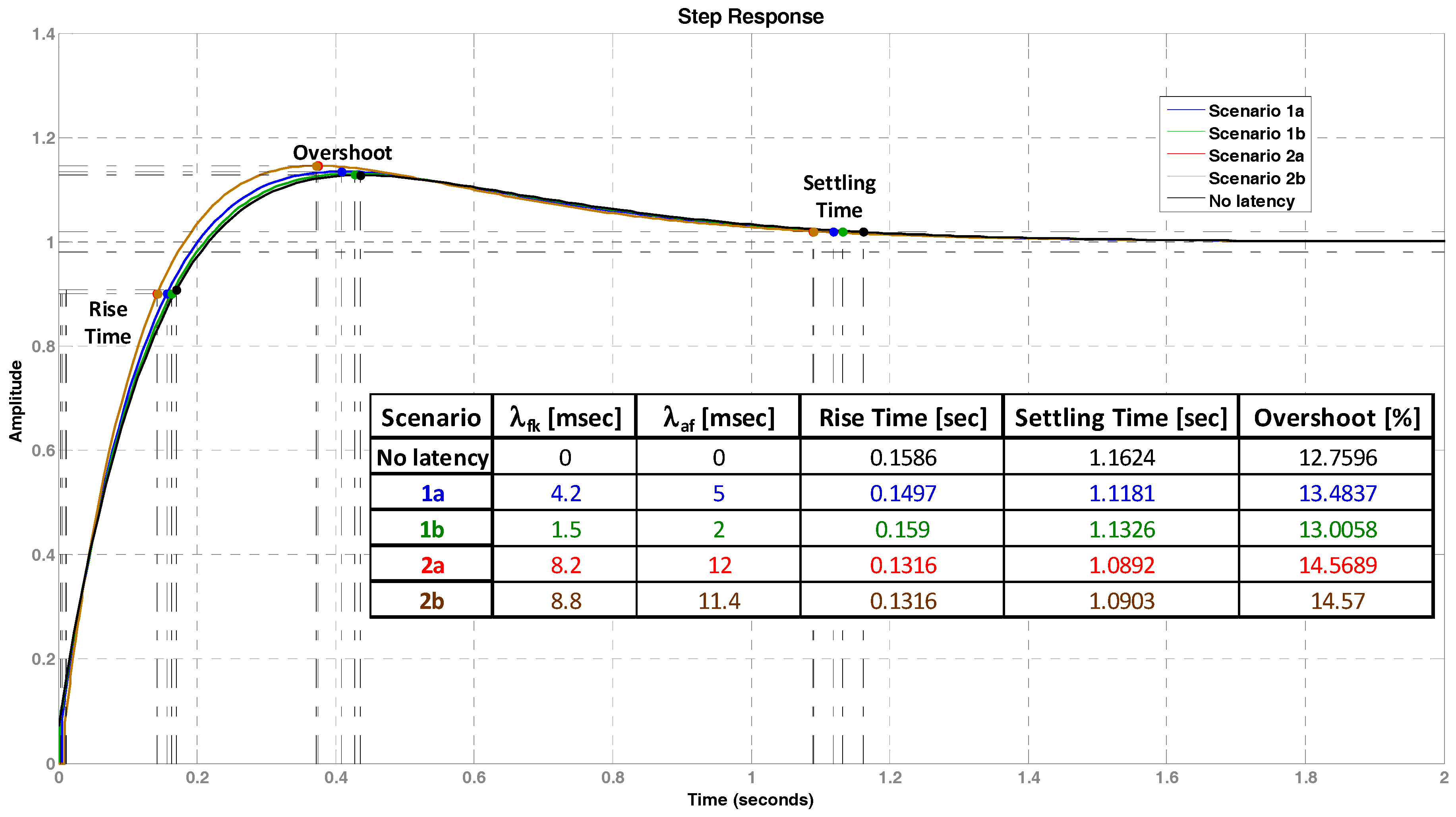
Figure 22 shows the time response (time domain) for a latency of 3.5 ms and 20.2 ms (the latency range provided by the DAA execution). The step input is normalized to a value of 1. There is a slight change on the overshoot (increment) as the GM and PM are reduced.
A comparison between characteristics of the FMMS response without and with latency for the worst cases (longer times and larger overshoots) shows that a variation of (1) the rise time of 0.027 s decrement (scenario 1b, deterioration), (2) the settling time of 0.0732 s decrement (scenario 1b, improvement), and (3) the overshoot of 1.81% increment (scenario 2b, deterioration).
7. Discussion
This section discusses the experimental results obtained and a comparison of the IEC-61499 standard with other modeling approaches for DAAs.
7.1. Experimental Results
The results obtained in Section 5 and Section 6 show it can be possible to support timing constraints when executing FBs from a DAA in a fully-deterministic (computation and communication) platform. The example makes use of the IMA and TTP technologies to provide full determinism through time partitioning and time triggering. Current IMA realizations in aircraft are connected by means of ADFX which provide a good degree of determinism by means of network calculus for latencies and jitters (bounded delays).
The DAA is simple, but it is enough to show how FBs can be scheduled and executed in order to meet RT requirements such as end-to-end flow latency. The DAA scheduling is trivial (sequential and non-preemptive scheduling). Parallelism only happens for execution of FBs in different devices (CPIOMs). The key of the runtime approach is to execute the (local) FBs synchronously as well as to have deterministic communication to reach global synchronization.
Scenario 1a (first strategy, off-line scheduling and one partition per CPIOM) shows that deterministic execution of FBs where partitions from different CPIOMs are synchronously executed at a time. Tasks (with a similar purpose, e.g., inputs of the controller) are executed in parallel in the same execution period when CPIOMs are different (0–2 ms) and one just after the other when the CPIOM is the same (3–5 ms). Scenario 1b (second strategy, on-line scheduling and subsequently continuous execution of FBs) shows that the same FBs can be all executed one after the other with obvious reduction of the end-to-end latency. The reduction is about the 62%. However, a faster completion of the end-to-end timing process does not mean more determinism or even better RT performance. Task execution jitters change the total process time.
Scenario 2a (first strategy, off-line scheduling and three partitions used in CPIOM-Control) shows that scenario 1a can be also deployed in more than one partition in the same CPIOM. The end-to-end latency is increased as the partitions must be switched for consecutive execution. Scenario 2b (second strategy, on-line scheduling, three partitions used in CPIOM-Control, and subsequently continuous execution of FBs) shows that scenario 1b can also be deployed in more than one partition in the same CPIOM. The end-to-end latencies in scenario 2a and 2b are the same since partitions dictate the elapsed time for the DAA execution.
The end-to-end latency calculus is rather defined by time slots than for the completions, jitters, or any other delays of the FB tasks. The variation of latency given by the range calculated is very small, and its impact on the RT performance of the DAA can be reflected in the control performance. Both scenarios involve non-preemptive scheduling (no chance of interruption whatsoever on the execution of tasks). This situation could well happen in avionics systems for more complex DAAs. Thus, further investigation is required to study preemptive scheduling (particularly, when the number of FB tasks is incremented). The execution design method absolutely depends on the available computing resources in any case. Nevertheless, the case study presented does not consider parallel computing from multicore processors, Field Programmable Gate Arrays (FPGAs), or Programmable Logic Devices (PLDs) for real computing parallelism.
The control performance analysis demonstrates that the end-to-end latency impact on the control loop of the DAA is insignificant. A latency of 20.2 ms means 1.81% more of the overshoot (14.2% change from overshoot without delay) in the time response, which also means a drop of the GM from infinity to 22.3 dB, and 14.3% reduction of the PM. The former tightens the maximum gain (to 22.3 dB) that can be added to the control loop before it becomes unstable. The above results mean that the DAA is stable even though an execution latency is introduced. They are only indicative values for a range of possible execution configurations of FBs. However, they are a way to show that the DAA execution can be temporally effective and efficient if it is executed as a fully deterministic platform. This demonstration is just a preliminary idea that requires further tests via computer simulations as well as laboratory prototypes.
7.2. Comparision with Other Modelling Techonologies
Most relevant modelling approaches for analysis and design of embedded RT software applications are profiles of the Unified Modeling Language (UML) such as the UML Profile for Schedulability, Performance, and Time (SPT) [30], the executable Unified Modeling Language (xUML) [31], Modeling and Analysis of Real-Time Embedded systems (MARTE) [32], and the Architecture Analysis and Design Language (AADL) [33]. The UML is a high-level description language that provides means for an abstract representation (independently of the execution hardware platform) for systems under study. The AADL provides notation for system representations along with analysis methods based on computation and communication models. The UML profiles and the AADL are meant to connect the software abstraction with the hardware characteristics to deal with quality factors (usually related to non-functional requirements).
The IEC-61499 standard and the above modeling languages have similarities and differences. They are all for graphical system representations aligned with structural high-level modeling as well as based on the class-object/datatype-instance construction mechanism for object-oriented analysis and design (including component-based system architectures). Although all these languages provide support for behavioral modeling, only some of them (SPT, xUML, and MARTE) particularly deal with timing issues. The strongest point of IEC 61499 is a way to encapsulate a structure and behavior in the same building element (the FB) that also includes the code to be executed and is part of the overall application. This places the standard in a unique position between conceptual abstraction (general purpose) and physical realization (specific domain) and provides a big picture for structural hierarchy and for behavioral hierarchy as to local and global scheduling. However, the standard does not have mechanisms to model timing specifications to predict determinism, and any IEC-61499 application behavior depend on runtime environment. A further discussion on pros and cons from the IEC-61499 standard for aerospace are available in earlier publications [3,12,13].
Table 3 shows advantages and disadvantages from the modeling approaches discussed above. The aspects evaluated from the modelling approaches are (1) specification of functional/non-functional properties, (2) support for model transformation, (3) type of reconfiguration mode, and (4) model distribution (mapping).
8. Concluding Remarks and Future Work
The ongoing improvement and modernization of avionics also bring along a technological evolution for the air-vehicle system architecture. This creates opportunities for research on engineering tools (tentatively, modeling technologies from one domain to another) to tackle the challenge of developing reliable time-critical DAAs. Effective modeling languages, distributed deployment, and execution of models are critical to design dependable avionics systems.
A simple end-to-end latency analysis of an IEC61499-modelled DAA has been discussed. The DAA model is based on the IEC 61499 standard (an industrial automation standard). The potential use of such a standard to model a DAA has been shown for a deterministic avionics platform as the modeled DAA is able to achieve desired runtime latency for temporal dependability. The above platform is provided by the combination of the IMA and TTP technologies that provides a fully synchronous execution platform for the DAA to guarantee predictive timing performance by means of temporally deterministic performance.
A case study of a distributed fuel control system of the Airbus A380-800 has been presented as a DAA example. A key driver for deterministic RT behavior has been identified and analyzed as the end-to-end latency between sensors and effectors. It depends on the scheduling of tasks in the control computer (computation) and messages (packets) in the TTP network (communication). Latency analysis and a discussion have been carried out to realize the above latency (including worst- and best-case latencies). Latency analysis results from timing metrics and closed-loop control simulation results have been presented. Experimental outcomes have suggested that an IEC61499-based DFCS model can achieve desired runtime latency for temporal dependability when executed in an IMA-TTP platform.
There are two main issues that will drive further investigation on this research. First, one of the issues is to develop an approach to endow the IEC-61499 standard with execution notation to specify how FBs are deployed and executed in a computation and communication platform (based on IMA and TTP or any other that provide fully deterministic execution). This issue is aligned with the concept proposed by the AADL [33] and the xUML [31]. Second, there are further execution situations of FBs that need attention. They are discussed in IEC-61499 publications regarding the parallel execution of FBs, cross-connected data and events, and preemptive FBs [34]. Future research will address the two remaining issues mentioned above.
Conflicts of Interest
The author declares no conflict of interest.
Appendix A
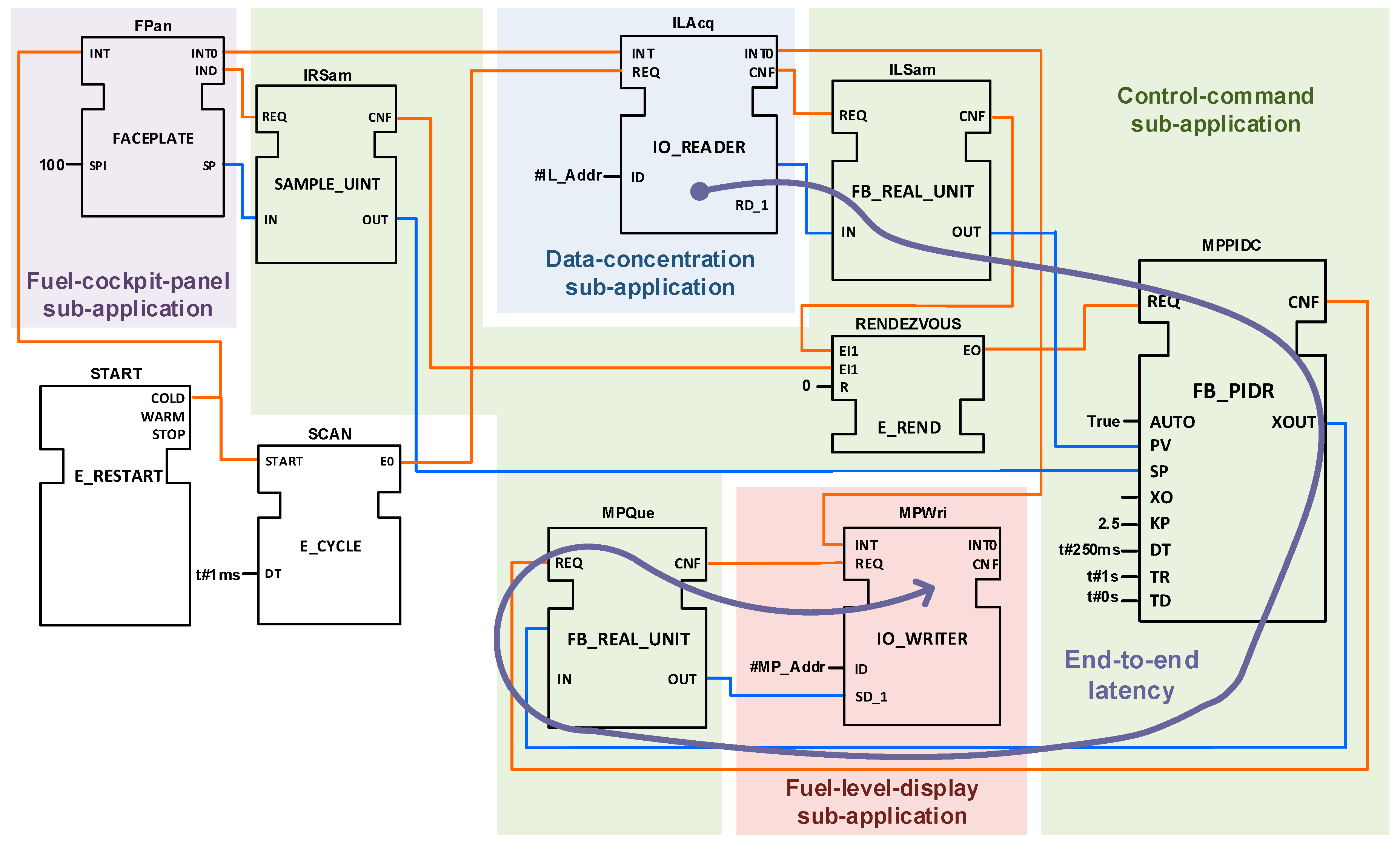
This appendix shows the FBs that define the main FMMS application. Each sub-application (as defined in Appendix A) is highlighted. The following FB diagram obviously does not include the publisher FBs or subscriber FBs used to split sub-applications from the main FMMS application. Figure A1 shows the FBs and their connections that form the main FMMS application along with the end-to-end latency studied.
Figure A1.
Main FMMS application.

Appendix B
Table A1 shows the FBs included in each sub-application. The duration of tasks is estimated and assigned longer than the FBs to consider real software blocks potentially required by the FMMS in the A380-800.

Table A1.
Function Blocks (FBs) of each sub-application.
| Sub-Application | Functionality | Function Block (FB) | Acron. | Duration (μs) |
|---|---|---|---|---|
| Data-concentration | ITT sensing | ITT Level Acquirer | ILAcq | 550 |
| ITT Level Publisher | ILPub | 200 | ||
| IEFT Level Acquirer | IELAcq | 550 | ||
| IEFT Level Publisher | IELPub | 200 | ||
| Control-command | Mid pump control | ITT Ref Subscriber | IRSub | 200 |
| ITT Ref Sampler | IRSam | 250 | ||
| ITT Level Subcriber | ILSub | 200 | ||
| ITT Level Sampler | ILSam | 250 | ||
| Mid Pump PID Controller | MPPIDC | 750 | ||
| Mid Pump Queuer | MPQue | 250 | ||
| Mid Pump Publisher | MPPub | 200 | ||
| IEFT Ref Subscriber | IERSub | 200 | ||
| Transfer pump control | IEFT Ref Sampler | IERSam | 250 | |
| IEFT Level Subcriber | IELSub | 200 | ||
| IEFT Level Sampler | IELSam | 250 | ||
| Transf Pump PID Controller | TPPIDC | 750 | ||
| Transfer Pump Queuer | TPQue | 250 | ||
| Transfer Pump Publisher | TPPub | 200 | ||
| ITT Ref Subscriber | IRSub | 200 | ||
| Mid Pump Subscriber | MPSub | 200 | ||
| Fuel-cockpit-panel | Pilot interface | Fuel Panel | FPan | 450 |
| Operation Mode Publisher | OMPub | 200 | ||
| ITT Ref Publisher | IRPUB | 200 | ||
| ITT Level Subcriber | ILSub | 200 | ||
| IEFT Level Subcriber | IELSub | 200 | ||
| Fuel-level-display | Fuel gauging | Mid Pump Subcriber | MPSub | 150 |
| Mid Pump Writer | MPWri | 50 | ||
| Transf Pump Subcriber | TPSub | 150 | ||
| Transf Pump Writer | TPWri | 50 |
References
- MIL-STD-1553B in Avionics: Where Data Networking Has Been and Where It’s Going. Available online: http://www.intelligent-aerospace.com/articles/2017/04/mil-std-1553b-in-avionics-where-data-networking-has-been-and-where-it-s-going.html (accessed on 30 January 2018).
- Gaska, T.; Watkin, C.; Chen, Y. Integrated Modular Avionics—Past, present, and future. IEEE Aerosp. Electron. Syst. Mag. 2015, 30, 12–23. [Google Scholar] [CrossRef]
- Insaurralde, C. Distributed control modeling standard from industrial automation for aerospace. In Proceedings of the 35th Digital Avionics Systems Conference (DASC), Sacramento, CA, USA, 25–29 September 2016. [Google Scholar]
- IEC 61499-1, Function Blocks—Part 1: Architecture, 2.0. ed. TC 65/SC 65B. 2012. Available online: https://webstore.iec.ch/publication/5506 (accessed on 7 November 2012).
- TTTech TTA Group. Time-Triggered Protocol TTP/C High-Level Specification Document; TTTech: Vienna, Austria, 2002. [Google Scholar]
- Langton, R.; Clark, C.; Hewitt, M.; Richards, L. Fuel System Design Examples. In Aircraft Fuel Systems, 1st ed.; Aeorspace Series; Moic, I., Seabridge, A., Langton, R., Eds.; John Wiley & Sons Ltd.: Chichester, UK, 2009; pp. 301–315. [Google Scholar]
- Feiler, P.; Hansson, J. Flow Latency Analysis with the Architecture Analysis and Design Language (AADL); Technical Note CMU/SEI-2007-TN-010; Carnegie Mellon: Pittsburgh, PA, USA, 2007. [Google Scholar]
- Air Traffic Organization, U.S. Department of Transportation. Handbook for Real-Time Operating Systems Integration and Component Integration Considerations in Integrated Modular Avionics Systems; U.S. Department of Transportation: New Jersey, WA, USA, 2008.
- Airlines Electronic Engineering Committee. ARINC Specification 653-1—Avionics Application Software Standard Interface; Aeronautical Radio, Inc.: Annapolis, MD, USA, 2003. [Google Scholar]
- SAE Aerospace Standard (AS). AS6003 TTP Communication Protocol; SAE Aerospace Standard: Kissimmee, FL, USA, 2011. [Google Scholar]
- Vyatkin, V. IEC 61499 as Enabler of Distributed and Intelligent Automation: State-of-the-Art Review. IEEE Trans. Ind. Inform. 2011, 7, 768–781. [Google Scholar] [CrossRef]
- Insaurralde, C.C.; Seminario, M.A.; Jimenez, J.F.; Giron-Sierra, J.M. IEC 61499 Model for Avionics Distributed Fuel Systems with Networked Embedded Holonic Controllers. In Proceedings of the 11th IEEE International Conference on Emerging Technologies and Factory Automation (ETFA), Prague, Chez Republic, 20–22 September 2006; pp. 388–396. [Google Scholar]
- Insaurralde, C.C.; Seminario, M.A.; Jimenez, J.F.; Giron-Sierra, J.M. FB-Oriented Approach to Model an Aircraft Distributed Control Architecture—Avionics Fuel Systems. In Automation Technology in Practice International; Oldenbourg Industrieverlag: München, Germany, 2008; Issue 1, pp. 33–42. [Google Scholar]
- Liu, X.; Cao, C.; Zhao, X.; Sun, J.; Zhu, J. Network performance Analysis of time-triggered Ethernet based on network calculus for DIMA. In Proceedings of the 34th Digital Avionics Systems Conference (DASC), Prague, Czech Republic, 13–17 September 2015. [Google Scholar]
- Hamadou, S.; Mullins, J.; Gherbi, A.; Beji, S. A time-triggered constraint-based calculus for avionic systems. In Proceedings of the 18th IEEE International Symposium on Real-Time Distributed Computing Workshops, Auckland, New Zealand, 13–17 April 2015. [Google Scholar]
- Hamadou, S.; Mullins, J.; Chareton, C.; Gherbi, A. Specifying avionic embedded systems by denotations of the time-triggered constraint-based calculus. In Proceedings of the 16th IEEE International Conference on Information Reuse and Integration, San Francisco, CA, USA, 13–15 August 2015. [Google Scholar]
- Han, Y.; He, F. Design of DIMA scheduling algorithm based on network partition integrating model. In Proceedings of the 33th Digital Avionics Systems Conference (DASC), Colorado Spring, CO, USA, 5–9 October 2014. [Google Scholar]
- Lauer, M.; Mullins, J.; Yeddes, M. Cost Optimization Strategy for Iterative Integration of Multi-Critical Functions in IMA and TTEthernet Architecture. In Proceedings of the 37th IEEE Annual Computer Software and Applications Conference Workshops, Kyoto, Japan, 22–26 July 2013. [Google Scholar]
- Jakovljevic, M. Synchronous/asynchronous Ethernet networking for mixed criticality systems. In Proceedings of the 28th Digital Avionics Systems Conference (DASC), Orlando, FL, USA, 23–29 October 2009. [Google Scholar]
- Jakovljevic, M.; Insaurralde, C.; Ademaj, A. Embedded cloud computing for critical systems. In Proceedings of the 33th Digital Avionics Systems Conference (DASC), Colorado Spring, CO, USA, 5–9 October 2014. [Google Scholar]
- Voss, S. Integrated Task and Message Scheduling in Time-Triggered Aeronautic Systems. Ph.D. Thesis, Duisburg-Essen University, Munich, Germany, 2010. [Google Scholar]
- Tamas-Selicean, D. Design of Mixed-Criticality Applications on Distributed Real-Time Systems. Ph.D. Thesis, Technical University of Denmark, Kongens Lyngby, Denmark, 2014. [Google Scholar]
- Scarlett, J.J.; Brennan, R.W. Evaluating a new communication protocol for real-time distributed control. Robotics Comput. Integr. Manuf. 2011, 27, 627–635. [Google Scholar] [CrossRef]
- Young, L.H. Modelling and Synthesis of Safety-Critical Software with IEC61499. Ph.D. Thesis, University of Auckland, Auckland, New Zealand, 2010. [Google Scholar]
- Dai, W.; Pang, C.; Vyatkin, V.; Christensen, J.H. Time-stamped event based execution semantics for industrial cyber-physical systems. In Proceedings of the IEEE 13th International Conference on Industrial Informatics (INDIN), Cambridge, UK, 22–24 July 2015; pp. 1263–1268. [Google Scholar]
- Hu, M.; Luo, J.; Wang, Y.; Veeravalli, B. Scheduling periodic task graphs for safety-critical time-triggered avionics systems. IEEE Trans. Aerosp. Electron. Syst. 2015, 51, 2294–2304. [Google Scholar] [CrossRef]
- The Function Block Development Kit (FBDK). Available online: http://www.holobloc.com/doc/fbdk/index.htm (accessed on 6 September 2017).
- Zoilt, A.; Lewis, R. Modelling Control Systems Using IEC 61499, 2nd ed.; IET Control Engineering Series 95; Institution of Engineering and Technology: Stevenage, Herts, UK, 2014; p. 26. [Google Scholar]
- Cervin, A.; Årzén, K.-E.; & Henriksson, D. Control Loop Timing Analysis Using TrueTime and Jitterbug. In Proceedings of the 14th IEEE International Symposium on Computer Aided Control System Design (CACSD), Munich, Germany, 4–6 October 2006. [Google Scholar]
- Object Management Group (OMG), UML Profile for Schedulability, Performance, and Time, Version 1.1. Available online: http://www.omg.org/spec/SPTP/About-SPTP/ (accessed on 30 January 2018).
- Mellor, S.J.; Balcer, M.J. Executable UML: A Foundation for Model-Driven Architecture; Addison-Wesley Professional: Boston, MA, USA, 2002. [Google Scholar]
- Object Management Group (OMG). A UML Profile for MARTE: Modeling and Analysis of Real-Time Embedded Systems; Report; Object Management Group: Needham, MA, USA, 2008. [Google Scholar]
- Architecture Analysis & Design Language (AADL)—Modeling Language for Safety-Critical Systems. Available online: http://www.aadl.info (accessed on 30 January 2018).
- Strasser, T.; Zoilt, A.; Christensen, J.H.; Sunder, C. Design and Execution Issues in IEC 61499 Distributed Automation and Control Systems. IEEE Trans. Syst. Man Cybern. Part C Appl. Rev. 2011, 41, 41–51. [Google Scholar] [CrossRef]
Figure 1.
Space/time-partitioned architecture in Integrated Modular Avionics (IMA).
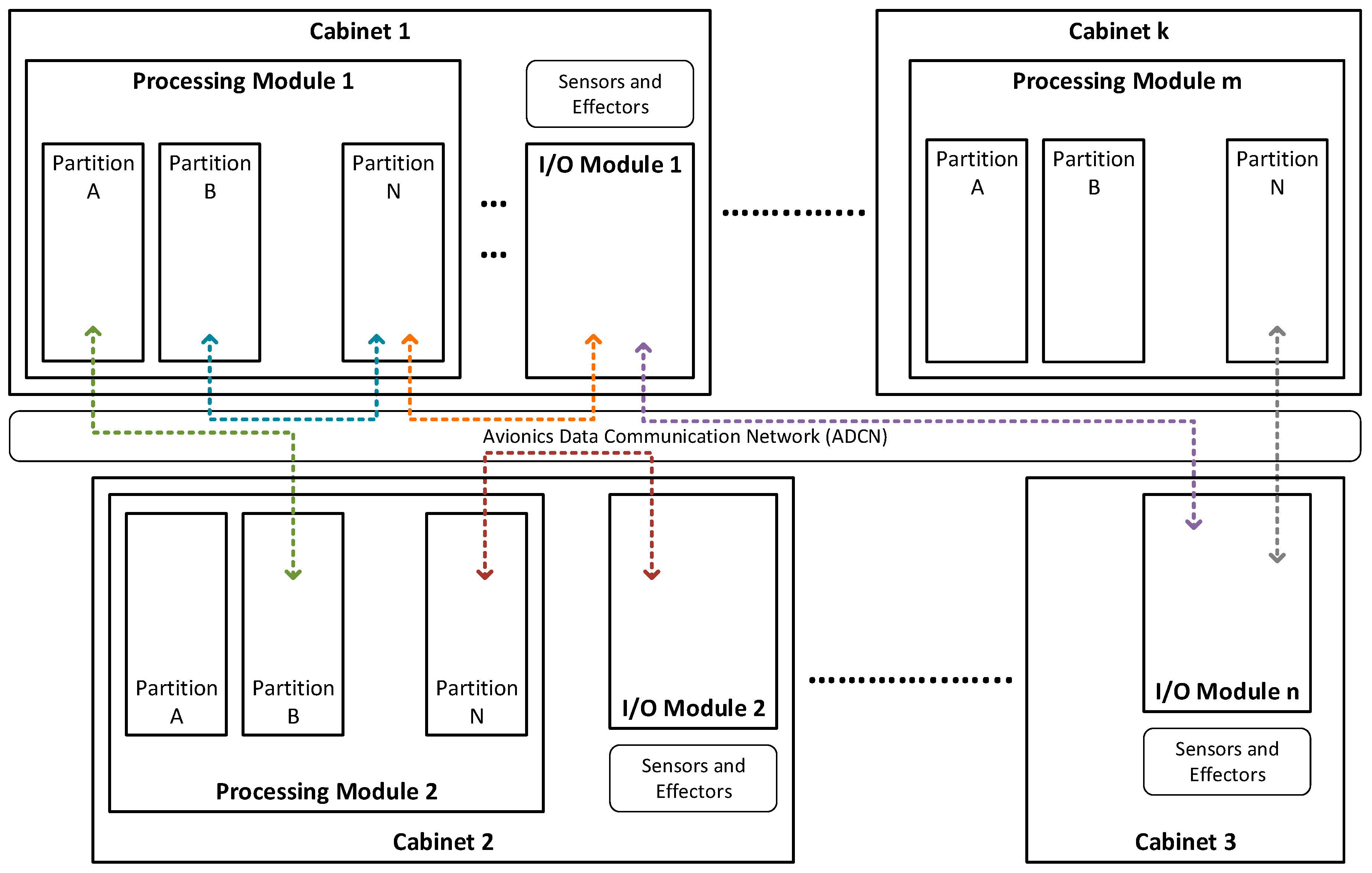
Figure 2.
Time-driven messaging in the Time-Triggered Protocol (TTP).
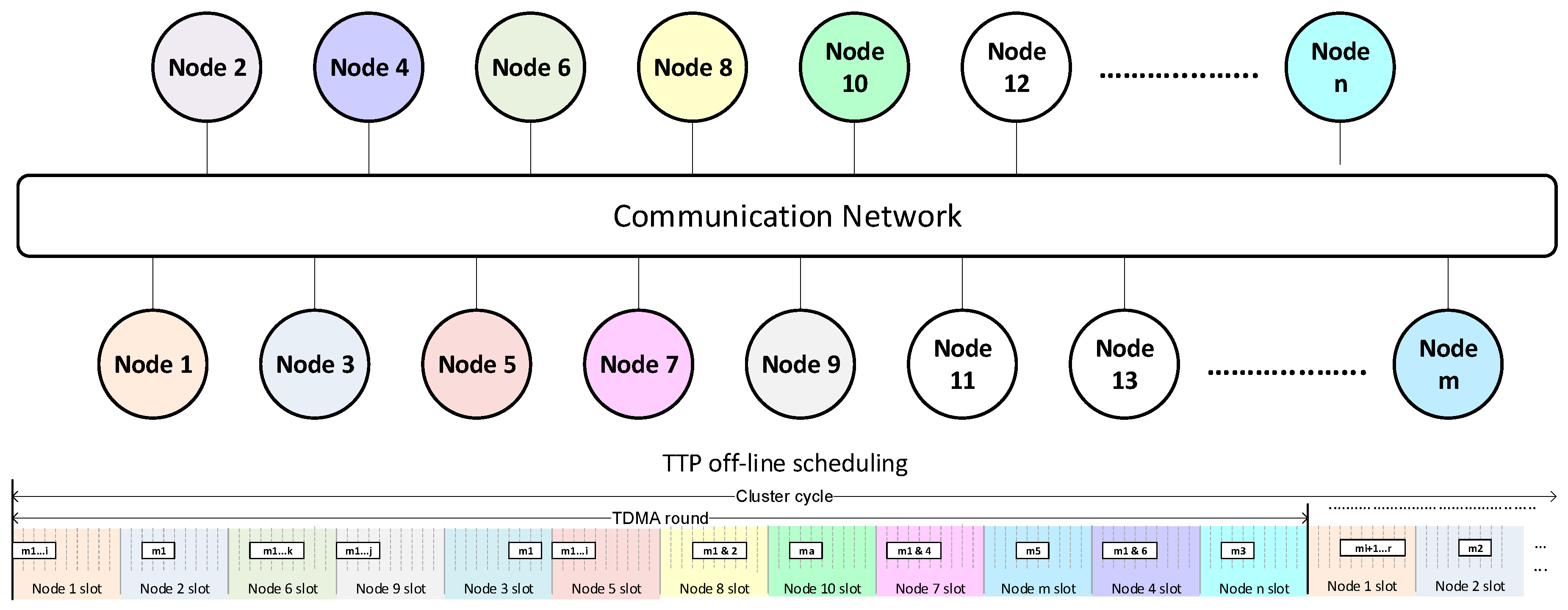
Figure 3.
Encapsulation and hierarchy of IEC-61499 models.
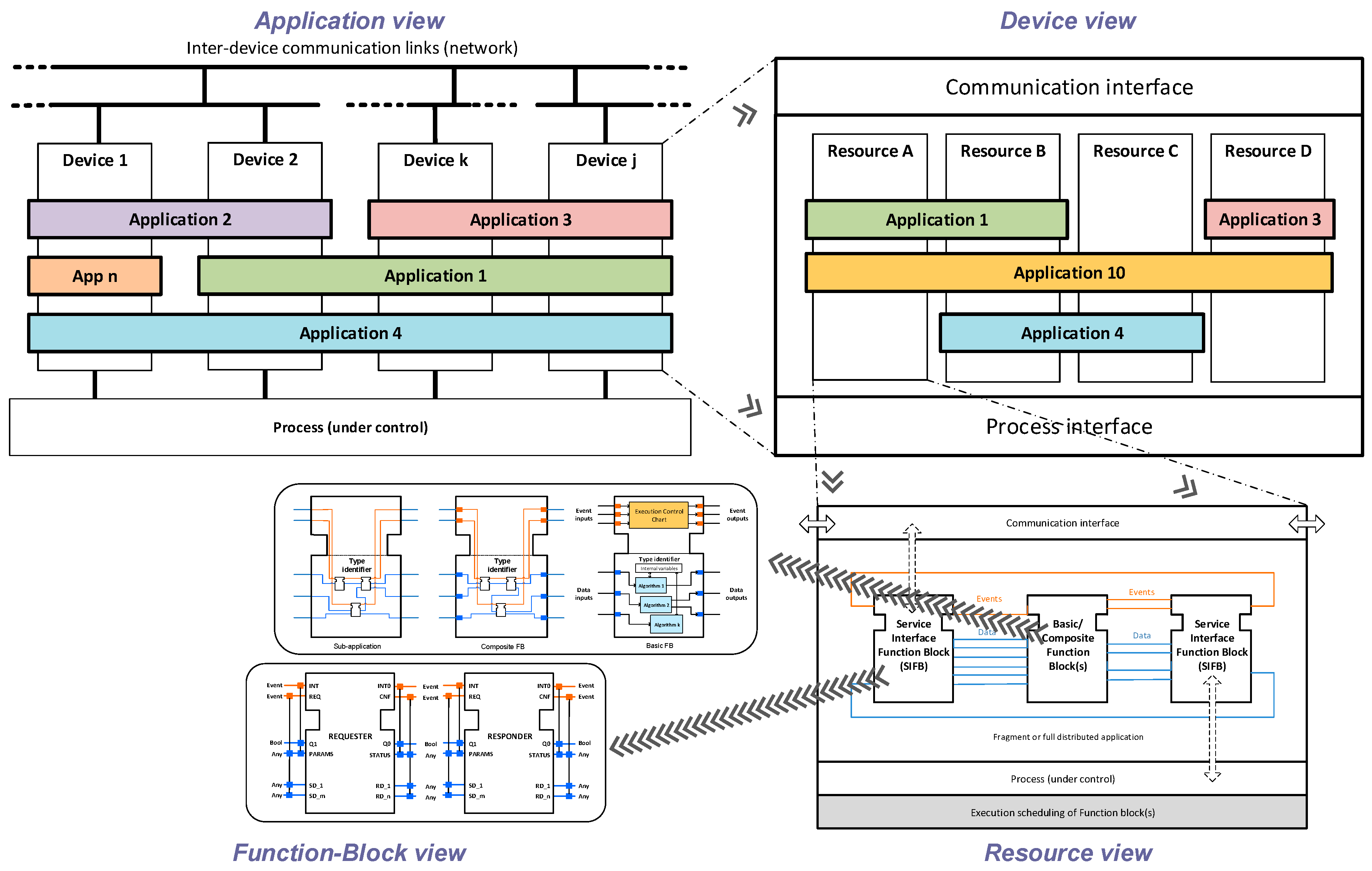
Figure 4.
Fuel tank system for the Airbus A380-800 left wing (adapted view from [6]).
Figure 4.
Fuel tank system for the Airbus A380-800 left wing (adapted view from [6]).

Figure 5.
Fuel measurement and management platform (adapted view from [6]).
Figure 5.
Fuel measurement and management platform (adapted view from [6]).

Figure 6.
Distributed fuel control application.

Figure 7.
Central Processor Input/Output Module (CPIOM)-Sensing device.

Figure 8.
CPIOM-Control device: device configuration for scenario 1 (top); Device configuration for scenario 2 (bottom).
Figure 8.
CPIOM-Control device: device configuration for scenario 1 (top); Device configuration for scenario 2 (bottom).
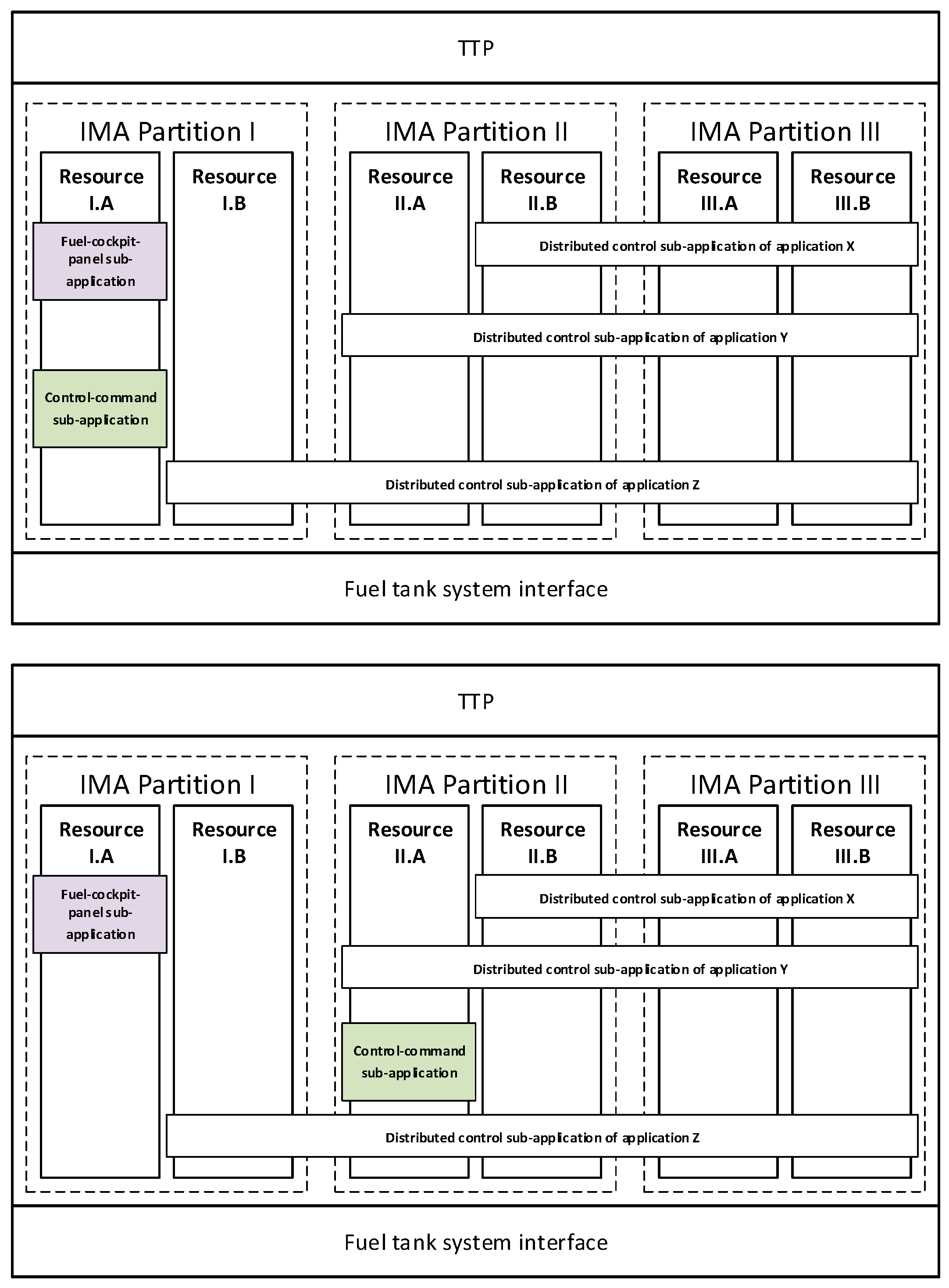
Figure 9.
CPIOM-Monitoring device: device configuration for scenario 1 (top); Device configuration for scenario 2 (bottom).
Figure 9.
CPIOM-Monitoring device: device configuration for scenario 1 (top); Device configuration for scenario 2 (bottom).
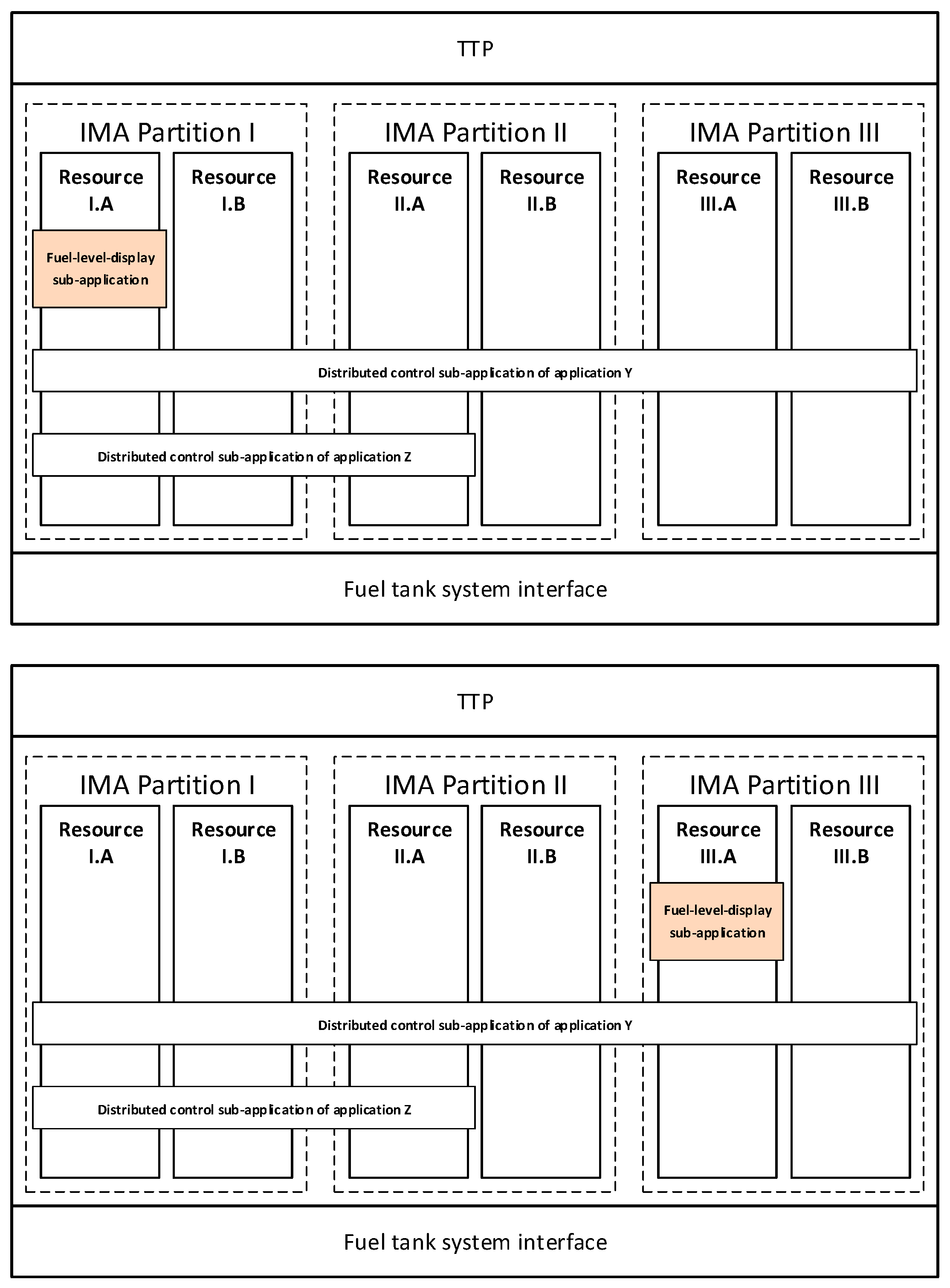
Figure 10.
Reassure I.A from CPIOM-Sensing device for scenario 1 and 2.
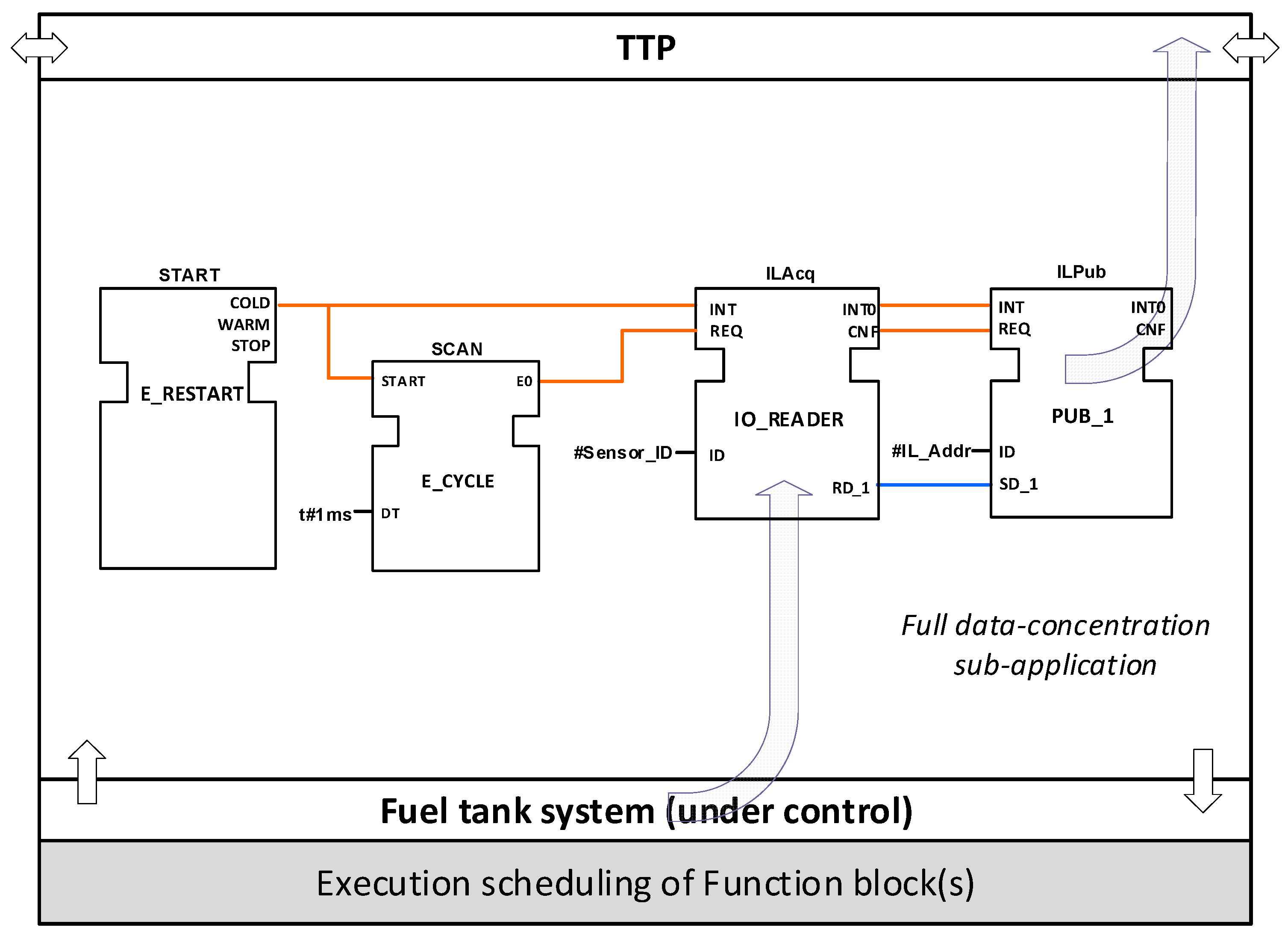
Figure 11.
Reassure I.A from CPIOM-Control device: resource configuration for scenario 1 (top); Device configuration for scenario 2 (bottom).
Figure 11.
Reassure I.A from CPIOM-Control device: resource configuration for scenario 1 (top); Device configuration for scenario 2 (bottom).

Figure 12.
Reassure II.A from CPIOM-Control device: resource configuration for scenario 2.

Figure 13.
Configuration of resource I.A from CPIOM-Control device for scenario 1 and resource III.A from CPIOM-Control device for scenario 2.
Figure 13.
Configuration of resource I.A from CPIOM-Control device for scenario 1 and resource III.A from CPIOM-Control device for scenario 2.
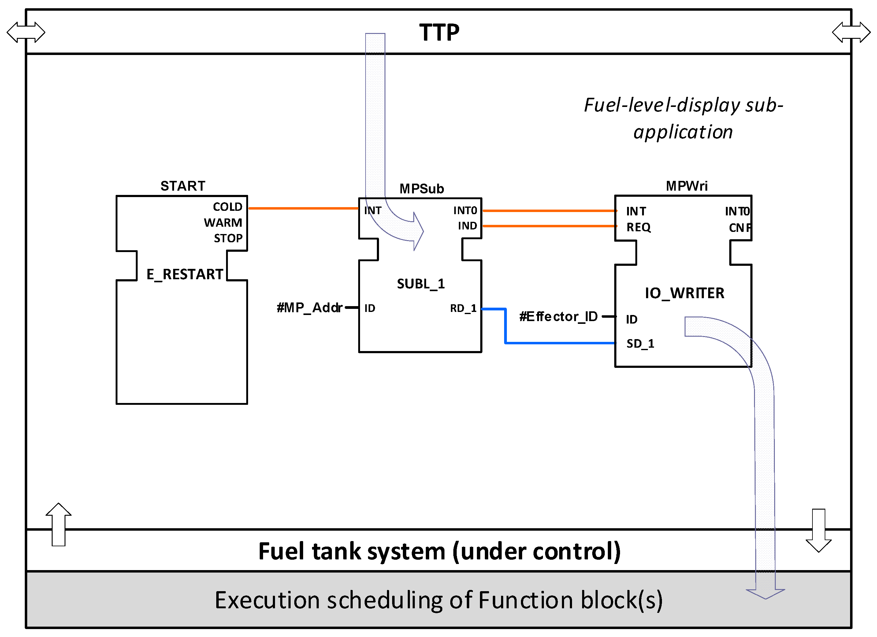
Figure 14.
Examples of executions of Function Blocks (FBs) according to the scheduling approaches.

Figure 15.
Scheduling strategy 1a of the FBs for the Inner Transfer Tank (ITT) control.

Figure 16.
Scheduling strategy 1b of the FBs for the ITT control.

Figure 17.
Scheduling strategy 2a of the FBs for the ITT control.

Figure 18.
Scheduling strategy 2b of the FBs for the ITT control.
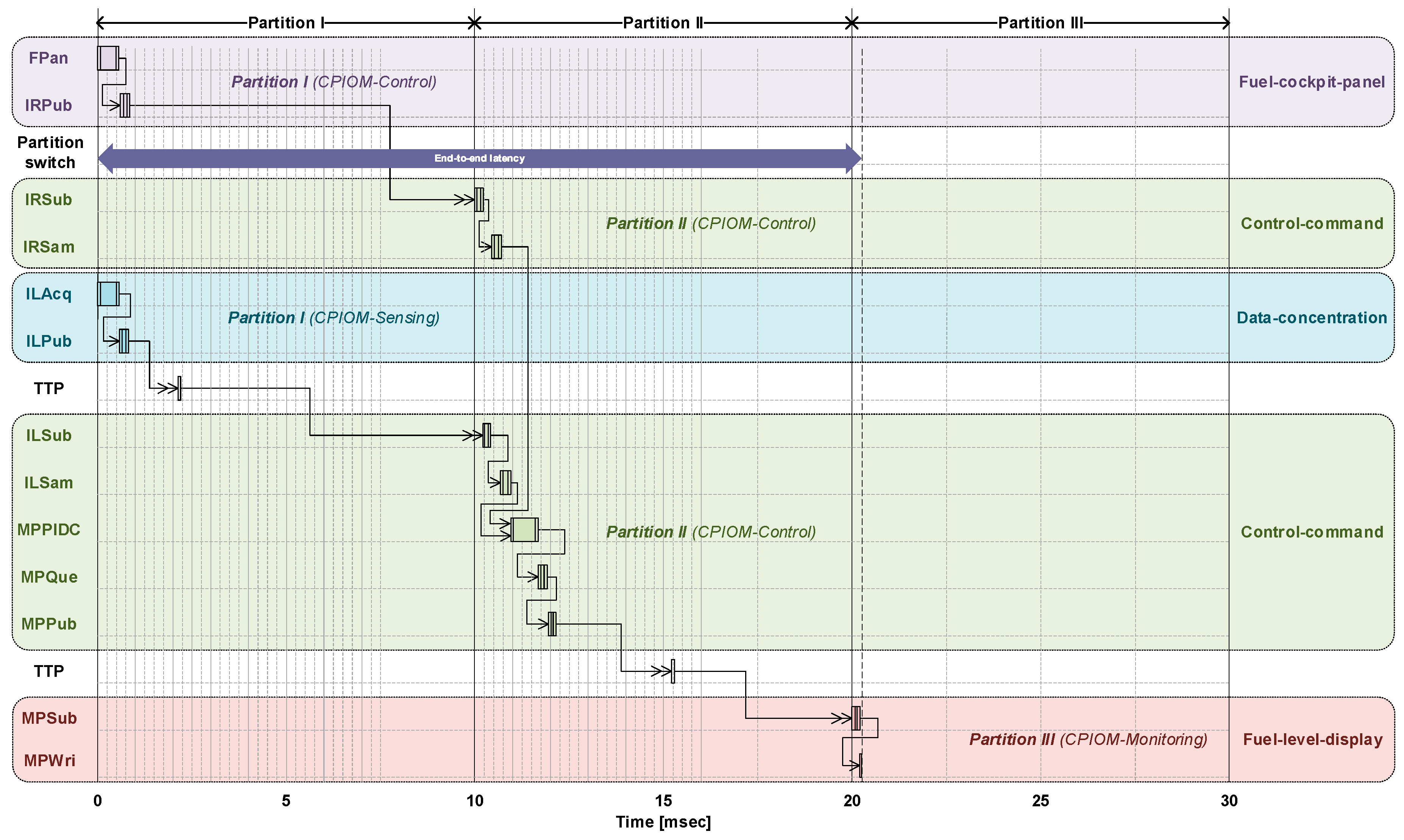
Figure 19.
End-to-end latency in the control loop of the Distributed Avionics Application (DAA).
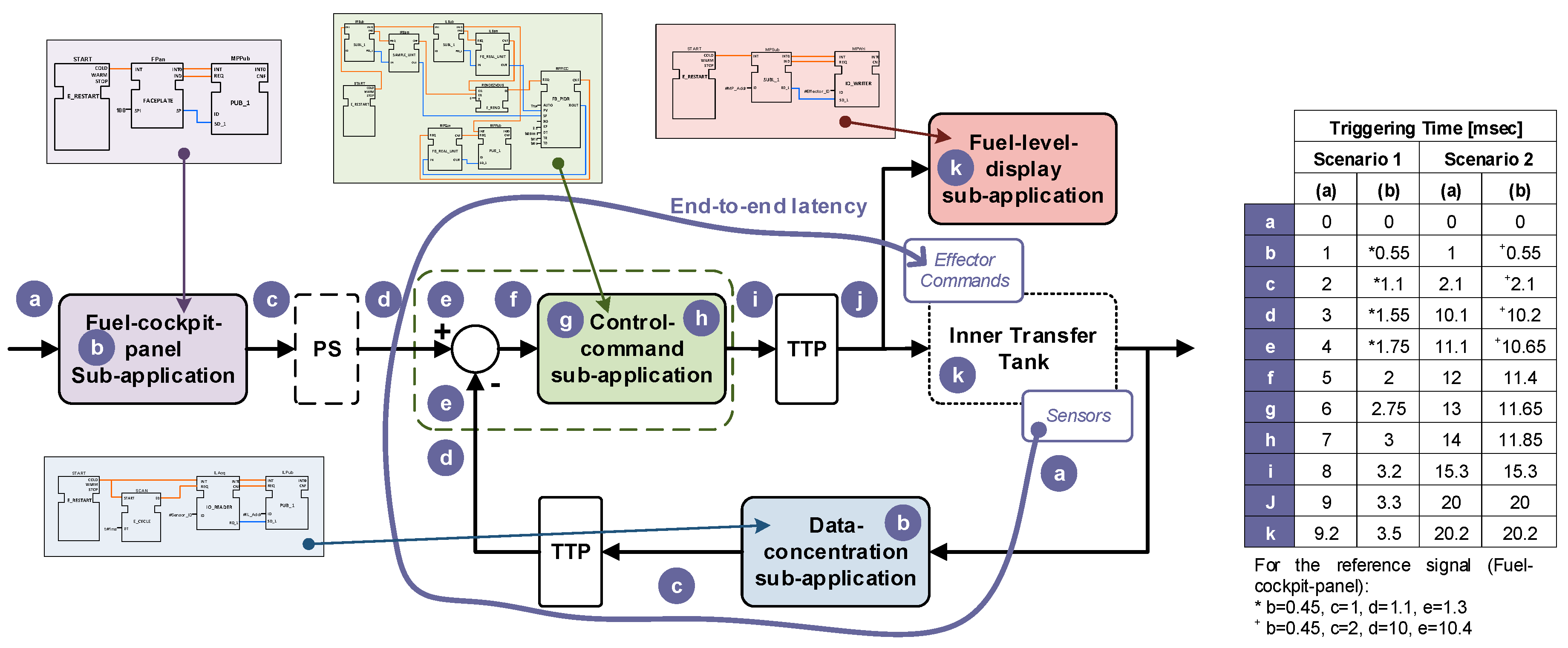
Figure 20.
Control model of the Fuel Measurement and Management System (FMMS).
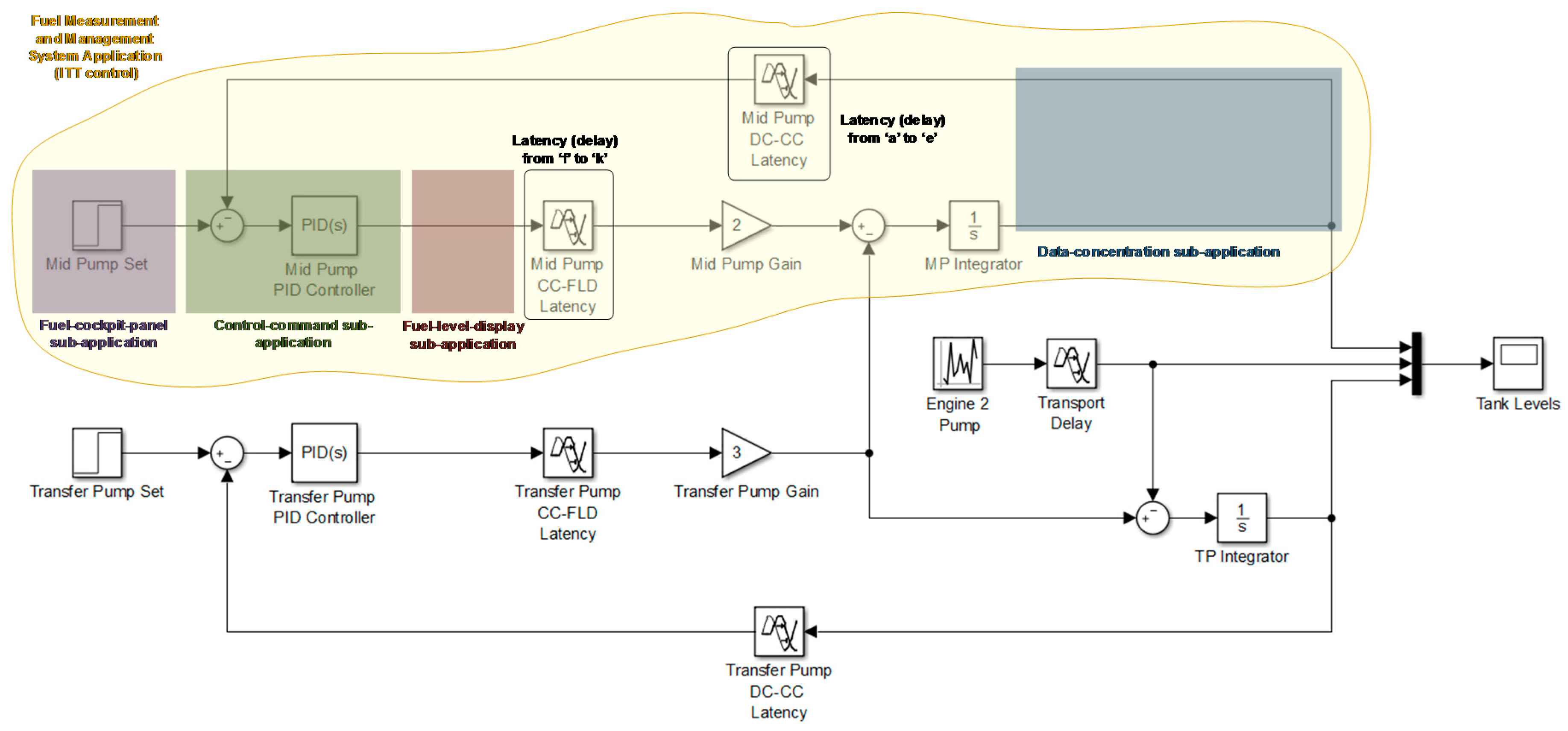
Figure 21.
Gain and phase margins as indexes of control stability.
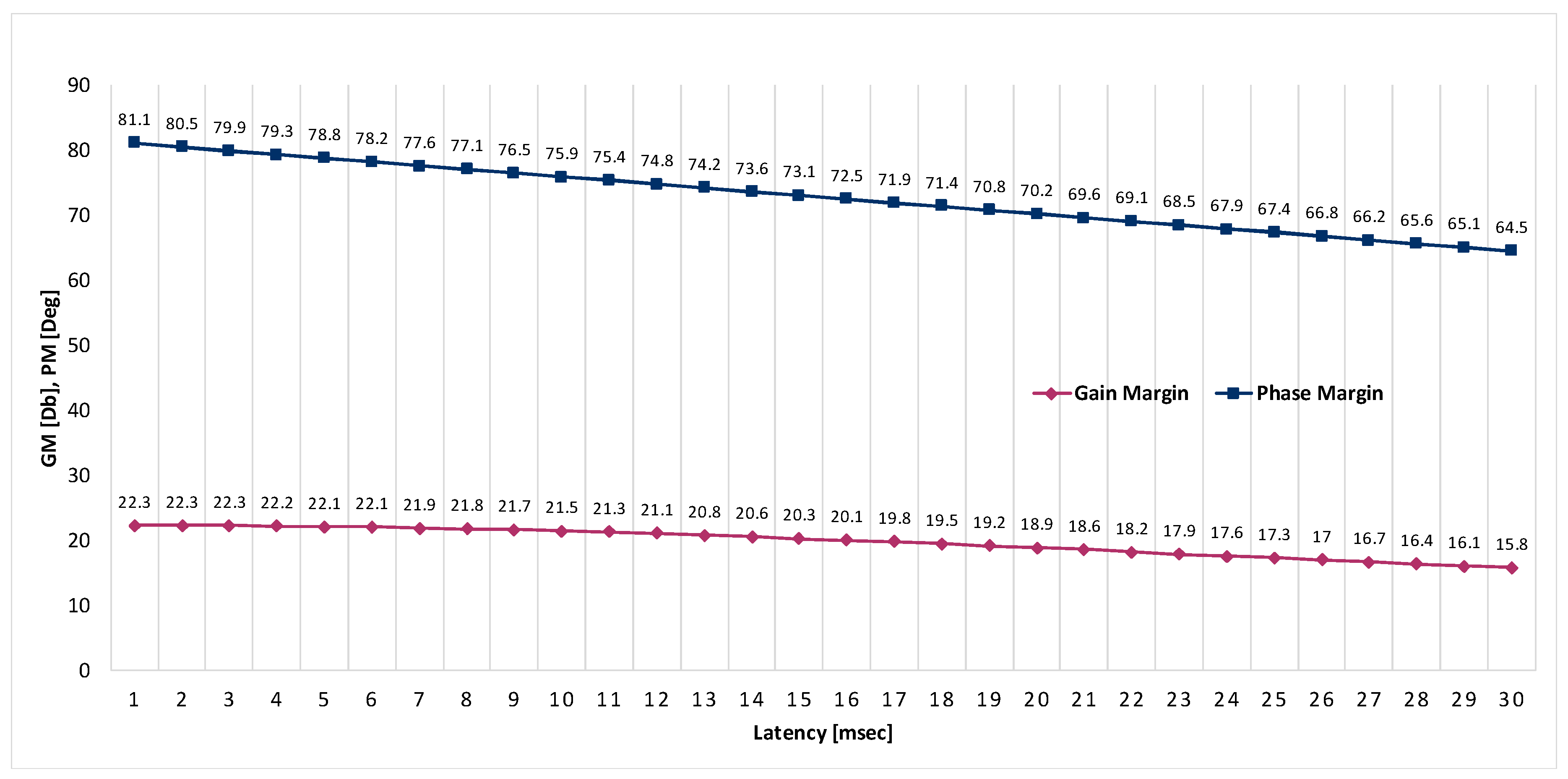
Figure 22.
Time response for an input (desired level) for the mid pump.

Table 1.
Allocation of deployed sub-applications (scenario 1).
| Device | Sub-Application | Functionality | Partition | Resource |
|---|---|---|---|---|
| CPIOM-Sensing | Data-concentration | ITT sensing | I | I.A |
| CPIOM-Control | Control-command | Mid pump control | I | I.A |
| Transfer pump control | ||||
| Fuel-cockpit-panel | Pilot interface | |||
| CPIOM-Monitoring | Fuel-level-display | Fuel gauging | I | I.A |
Table 2.
Allocation of deployed sub-applications (scenario 2).
| Device | Sub-Application | Functionality | Partition | Resource |
|---|---|---|---|---|
| CPIOM-Sensing | Data-concentration | ITT sensing | I | I.A |
| CPIOM-Control | Control-command | Mid pump control | II | II.A |
| Transfer pump control | III | III.B | ||
| Fuel-cockpit-panel | Pilot interface | I | I.A | |
| CPIOM-Monitoring | Fuel-level-display | Fuel gauging | III | III.A |
Table 3.
Comparison of the modeling approaches.
| Approach | Specification | Transformation | Reconfiguration | Distribution |
|---|---|---|---|---|
| UML | Functional | Platform-independent | Static | Local |
| SPT | Non-functional: Time | Platform-independent/dependent | Static | Local |
| xUML | Functional and non-functional | Platform-independent/dependent | Static | Local |
| MARTE | Non-functional: Time and alocation | Platform-independent/dependent | Static | Local |
| AADL | Functional and non-functional | Platform-independent/dependent | Static | Local/global |
| IEC61499 | Functional | Platform-independent | Static/dynamic | Local/global |
© 2018 by the author. Licensee MDPI, Basel, Switzerland. This article is an open access article distributed under the terms and conditions of the Creative Commons Attribution (CC BY) license (http://creativecommons.org/licenses/by/4.0/).
Share and Cite
MDPI and ACS Style
Insaurralde, C.C. Fully-Deterministic Execution of IEC-61499 Models for Distributed Avionics Applications. Aerospace 2018, 5, 15. https://doi.org/10.3390/aerospace5010015
AMA Style
Insaurralde CC. Fully-Deterministic Execution of IEC-61499 Models for Distributed Avionics Applications. Aerospace. 2018; 5(1):15. https://doi.org/10.3390/aerospace5010015
Chicago/Turabian StyleInsaurralde, Carlos C. 2018. "Fully-Deterministic Execution of IEC-61499 Models for Distributed Avionics Applications" Aerospace 5, no. 1: 15. https://doi.org/10.3390/aerospace5010015
Note that from the first issue of 2016, this journal uses article numbers instead of page numbers. See further details here.