Pneumatically Powered Drilling of Carbon Fibre Composites Using Synthetic Biodegradable Lubricating Oil: An Experimental Study

School of Computing, Science and Engineering, University of Salford, Salford M5 4WT, UK
*
Author to whom correspondence should be addressed.
Aerospace 2018, 5(1), 9; https://doi.org/10.3390/aerospace5010009
Submission received: 27 November 2017
/
Revised: 7 January 2018
/
Accepted: 11 January 2018
/
Published: 16 January 2018
(This article belongs to the Special Issue Adaptive/Smart Structures and Multifunctional Materials in Aerospace)
Abstract
:Carbon fibre composites are a key component of aircraft structures because of their enhanced material properties such as favourable strength to weight ratios when compared to metal alloys. During the assembly process of an aircraft, carbon fibre components are joined to other structures using rivets, bolts, and fasteners, and as part of the joining process, the components will need to be machined or drilled. Unlike metal alloys, composites are sensitive to heat and are vulnerable to internal structural damage from machining tools. They are also susceptible to a reduction in strength when fibres are exposed to moisture. In the machining process, carbon fibre composites may be drilled using oils to lubricate carbide machining tools. In this study, a description of the experimental apparatus is provided along with an investigation to determine the influence synthetic biodegradable lubricating oil has on drill rotational speed, drilling load, and drilling temperature when using a pneumatic drill to machine carbon fibre composite material.
1. Introduction
Materials have always been an integral part an aircraft’s design process, and today, carbon fibre composites are much cheaper to manufacture on a large industrial scale and are used extensively in the aerospace industry where strength to weight ratios are key to performance and efficiency. There are many aircraft manufacturers that utilise carbon composites in building aircraft; Boeing and Airbus are currently producing civilian aircraft where carbon composite components contribute approximately half of the aircraft’s primary material to help lower aircraft weight and maximise efficiency.
Machining of composites is a large proportion of the total manufacturing hours in building an aircraft including tasks such as drilling, cutting, reaming, routing, sanding, and milling. The machining of fibrous composites can affect the performance of the material by discontinuing the fibre strand, which causes the resin to transfer the load to adjoining fibres. It also exposes fibres to the local environmental conditions. During the machining process for carbon-epoxy materials, 50% of the heat due to friction during machining is absorbed by the workpiece, whilst the other 50% is absorbed by the tool. This is far greater than in metals, where the chips that occur during the cutting by the machining tool absorb 75% of total heat created, with the tool absorbing 18%, and the metal being worked absorbs just 7% [1].
The cutting tools used to machine composites are similar geometrically to those used in machining metals. However, due to the abrasive nature of composites, these tools are generally coated with carbide, titanium nitride, diamond, or tungsten to help prevent excessive wear and help to prolong tool life.
Care also needs to be taken when drilling through laminated composites since the drill bit can cause delaminations [2] in the top layer of plies due to peeling (Figure 1a). The drill bit also causes delaminations on the bottom plies as the drill pushes out of the other side (Figure 1b). In the latter case, backing material such as wood or metal is recommended when drilling through composites as this helps to support the material being drilled and reduces delamination.
The Helix angle of a drill bit is the angle between the cutting face of the drill and the direction of force being applied. If the angle is negative, it effectively pushes the fibres and chips into the composite instead of extracting them. This causes more force to act through the drill bit in order to penetrate the composite which also produces heat that can cause further delaminations in the composite. Positive Helix angles give a more pointed tip that cut through the fibres more effectively, and it also extracts chips and requires less force to go through the drill site. However, positive Helix angles can result in a more fragile drill bit [3].
When drilling though carbon composite material, an appropriate feed rate needs to be determined since using a low feed rate can damage the composite or the drill bit, and a feed rate that is too high will increase the load and cause delamination on the exit side of the hole [3]. Spindle speed is also a key aspect of drilling since, if too slow, the drill bit will smear and push against the carbon fibres. If the spindle speed is too fast, it causes local heat generation, which makes the resin sticky and produces lumpy chips [3]. Lazar and Xirouchakis [4] state that the load forces (axial and tangential) on the carbon fibre composite are predominantly affected by the feed rate and tool geometry, while spindle speed has little or no influence. Phadnis et al. [5] state that whilst using a constant spindle speed of 2500 rpm, the feed rate has a direct correlation to the force acting on the drill and carbon composite. Specifically, when the feed rate was increased from 150 mm/min to 300 mm/min and 500 mm/min, the thrust force increased by 50% and 76%, respectively.
Water is also known to have a detrimental impact on the internal structural integrity of epoxy-based composites. Moisture can act as a plasticizer when absorbed by the epoxy matrix, which leads to a reduction in the mechanical properties by effectively ‘softening’ the material [6,7] and reducing the glass transition temperature [7]. It can also migrate along the fibre-matrix interface, which can reduce the adhesion between the two.
Experimental work conducted by Chen [8] investigated drilling of fibre reinforced plastics (CFRP). It was noted that within this study, all drilling tests were conducted without coolant and used embedded thermocouples within the specimens to measure the flank surface temperature of the drill when drilling multidirectional CFPR composite laminates of 2 mm thickness. The effects of cutting speed and feed rate were discussed and found that flank surface temperatures of the drill increased with cutting speed but deceased with feed rate.
Abrão et al. [9] conducted a review of drilling glass and CFRP materials, with specific focus on tool materials and geometry, and the influence of machining parameters (e.g., cutting speed and feed rates) on thrust force and torque. Temperature effects were also briefly covered in relation to increased heat generation due to the low coefficient of thermal conduction of plastics.
In 2012, Liu et al. [10] also conducted a review of the mechanical drilling of composite laminates that covered topics such as cutting speed and feed rate but also included significant discussion on drill geometry (for example, point angle and drill bit twist). The paper highlights that an increase in thrust force is observed with an increase in the number of drilled holes. The main conclusions were that feed rate made a significant contribution to delamination, thrust force and tool wear.
2. Experimental Set-Up
The aim of this study is to investigate the effects of using synthetic biodegradable lubricating oil whilst through hole drilling carbon fibre composites with a pneumatically powered drill. The composite samples were made with eight layers of TenCate’s E726 epoxy resin (TenCate Advanced Composites, Nottingham, UK) pre-impregnated with high strength carbon fibres in a 2 × 2 twill woven arrangement [11], with a layup sequence of [0/90/0/90]S to give a cured thickness of 2 mm. The feed rate, spindle speed and drill bits were selected to represent typical hand operated drilling aerospace manufacturing methods. Half of the samples were drilled dry using no lubrication, and the remaining half drilled using a synthetic biodegradable oil mist. To avoid contamination, all dry drilling was conducted first. The results presented in this paper are an average of three experimental test runs for each test condition.
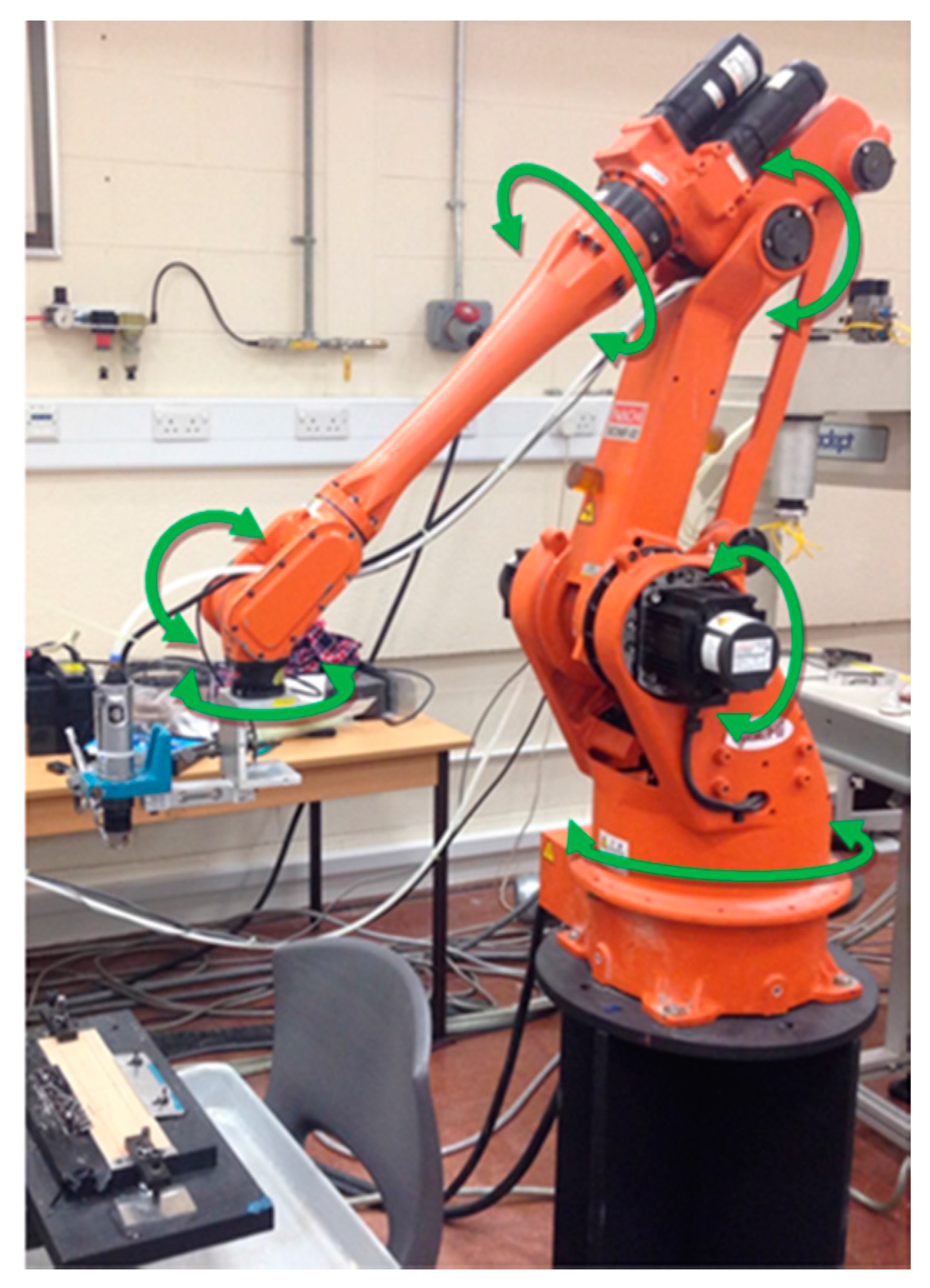
The test equipment consisted of an Ingersoll Rand LA410-EU pneumatic drill (Ingersoll Rand, Preston, UK) attached to an Nachi SC06F-02 industrial robotic arm (Nachi-Fujikoshi Corp., Toyama, Japan) (Figure 2). The pneumatic drill was powered using the laboratory pressurised air supply, which permitted control of the rotational speed by use of an air supply regulator. The drill had a free rotational speed of 4500 rpm. However, under drilling conditions, the maximum spindle speed of the drill was 2750 rpm. For this study, four different speeds were investigated—1700, 2100, 2400, and 2750 rpm—since these were typical speeds associated with hand-operated drilling operations performed in industry. The Nachi SC06F-02 industrial robotic arm was programmed to control drill position and feed rate in a process that permitted a high level of accuracy and repeatability between tests.
To measure the drilling force, a calibrated load cell was attached between the pneumatic drill and robot arm. The spindle speed was monitored by attaching a reflective strip to the pneumatic drill chuck to act as a reference point to reflect a laser back to a calibrated AT-6 Digital tachometer. The drill bit used was a solid Carbide Kennedy KEN158-3600K Ø6 designed specifically for drilling carbon composites. The drill bit specifications were: diameter 6 mm, point angle 118°, and helix angle 30°. A new drill bit was used for each hole drilled.
The synthetic biodegradable oil lubricant used in this study was Lubricool 2032-ACS2 (TPI—Techni Pro Industries, Saint Prix, France) since it is widely used in the aircraft industry and has a low viscosity making it suitable for micro spraying (Table 1).
The lubricating oil mist was applied using an airbrush attached to the robot arm that sprayed directly onto the end of the drill bit (Figure 3). The airbrush could be adjusted to produce different spray patterns. In order to maximise the output of the spray gun, the mist was set to its largest spray coverage by using a nozzle diameter of 0.5 mm, which produced a flow rate of 0.423 mL/s.
The carbon fibre samples were secured in place using clamps to stop them being picked up and bent by the drill bit as the plate was drilled. This arrangement was attached to a sturdy drilling table that was firmly fixed to the laboratory floor. The heat generated whilst drilling the carbon fibre specimens was monitored using a Forward Looking Infrared Camera (FLIR) E60BX thermal imaging camera that was aligned to measure the spot immediately adjacent to where the drill bit cuts through the specimen. The camera was set up one metre away from the drilling table so as to not interfere with the movement of the robotic arm and to also ensure the camera was not affected by the synthetic oil mist being sprayed onto the specimen (Figure 4).
3. Results
3.1. Spindle Speed and Feed Rate
In order to investigate the differences in spindle speed, this study compared the effects of drilling through carbon composite at initial spindle speeds of 1700, 2100, 2400, and 2750 rpm, with and without the use of synthetic biodegradable oil mist. The results for the dry and oil mist (wet) drilling are shown in Figure 5 with graphs annotated using capitalised letters to identify key points that will be referred to in the text.
In Figure 5a, it can be seen that in both tests a decrease in spindle speed from 1700 rpm occurs slightly before the drill bit snags on the material and reduces to an rpm of zero. The spindle speed starts to decrease for both specimens at the 7 s mark (A). After an initial drop in spindle speed, the dry test stops drilling at the 9 s mark (B), while the wet test continued briefly longer and stopped at the 10 s mark (C).
Figure 5b shows the relationship between the performance of the wet and dry tests at an initial spindle speed of 2100 rpm. It can be seen that at the 8 s mark, both tests experience an initial drop in spindle speed (D). The wet test decreases spindle speed by 8% by the 9 s mark (E) but then recovers and rapidly and returns to within 0.4% of the initial spindle speed by the 10 s mark (F). However, the spindle speed of the dry test drops quickly to 48.6% of the original spindle speed by the 9 s mark (G) before fully snagging at the 11 s mark (H).
Figure 5c presents the performance of the wet and dry tests with an initial spindle speed of 2400 rpm. The dry drilling test reduces spindle speed by a maximum of 40% at the 10 s mark (I), whereas there is almost negligible change in spindle speed for the wet drilling test with a maximum recorded reduction in spindle speed of only 1.3%.
Figure 5d presents the relationship between the performance of the wet and dry tests with an initial spindle speed of 2750 rpm. The drilling profile is similar to the results of the 2400 rpm test. At the 8 s mark (J) the dry spindle speed test experiences a reduction of 17%. The wet drilling test results present another almost negligible spindle speed decline of only 1.4% at the 8 s mark.
3.2. Drilling Loads
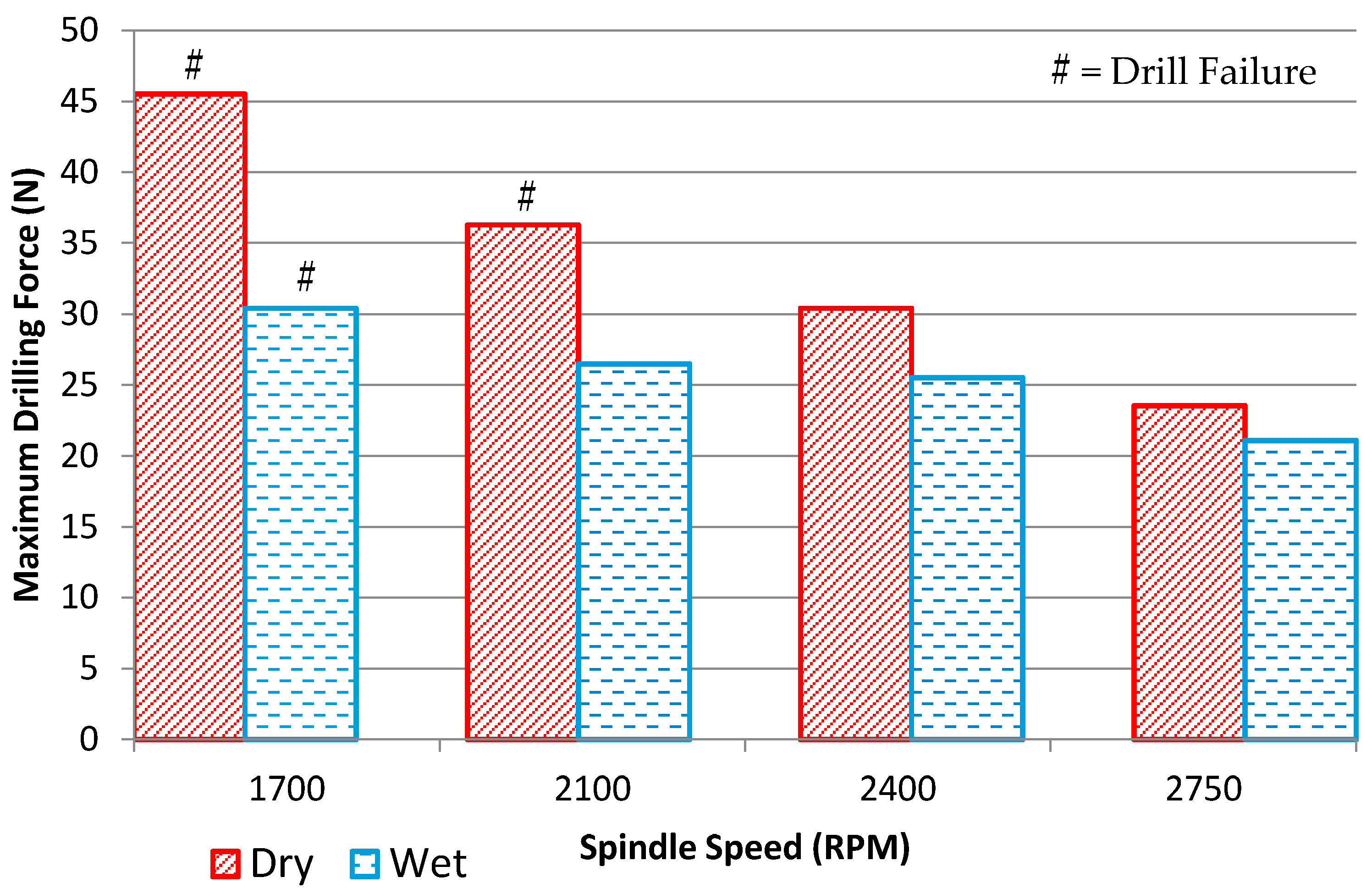
The load cell measurements taken during the spindle speed drilling tests are shown in Figure 6, which shows the difference between maximum wet and dry drilling force for 1700, 2100, 2400, and 2750 rpm are 33.2%, 27.0%, 16.1%, and 10.4%, respectively. It should be noted that drilling tests for 1700 rpm (wet and dry) and 2100 rpm (dry) were unable to completely drill through the carbon fibre specimen due to drill bit failure.
3.3. Drilling Temperature
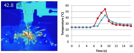
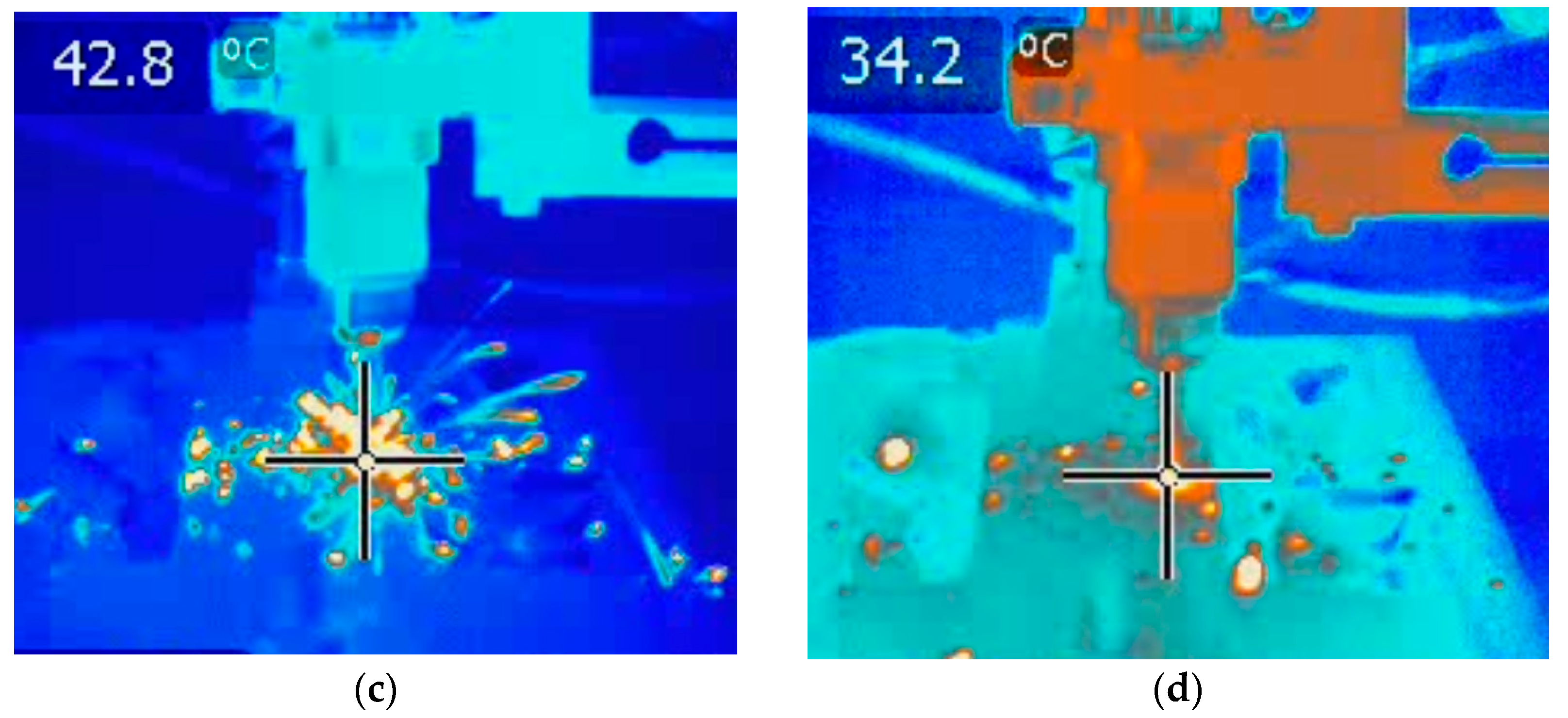
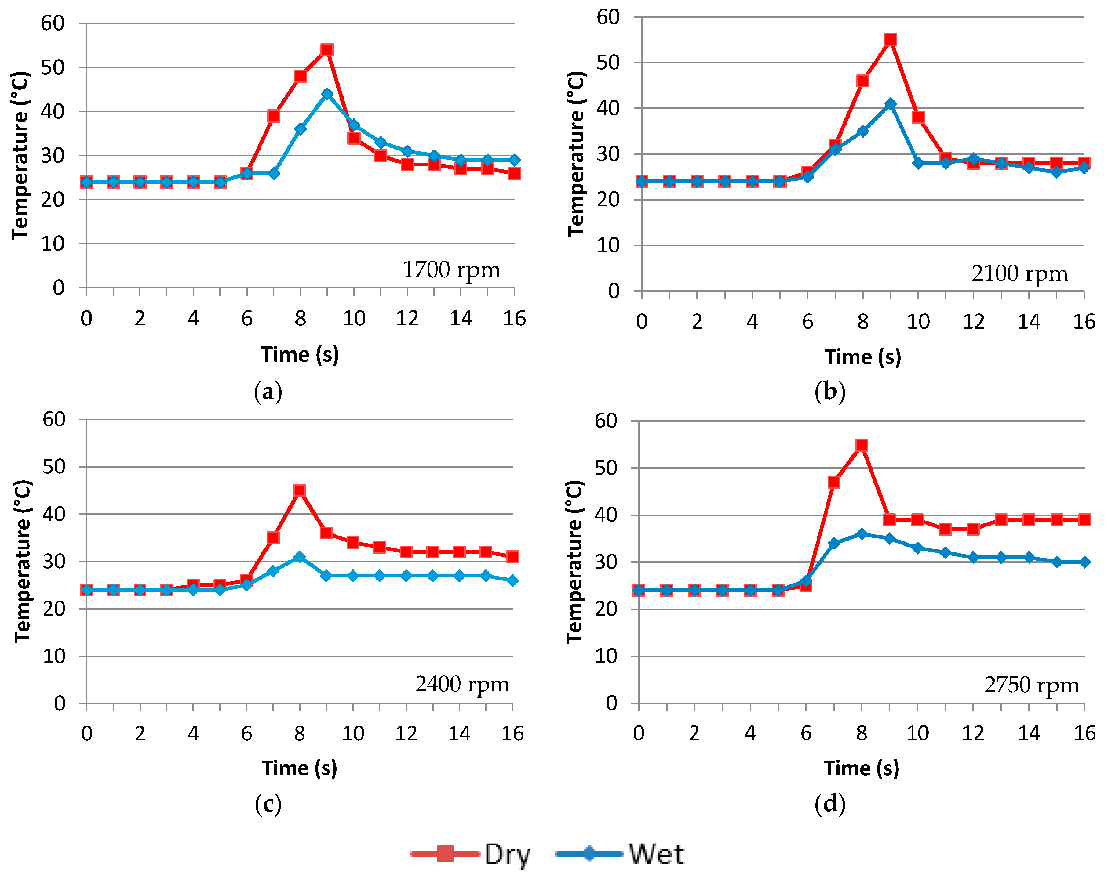
The FLIR thermal imaging data is shown in Figure 7 for dry and wet drilling temperatures for each of the initial spindle speed tests. The initial temperature of the specimens all started at a room temperature of 24 °C.
The maximum temperature recorded for wet and dry drilling combinations were found to occur for a spindle speed of 1700 rpm where the temperatures were 44 °C and 55 °C, respectively (Figure 7a). The minimum temperatures recorded for wet and dry drilling were found for the spindle speed of 2400 rpm where the temperatures were 31 °C and 45 °C, respectively (Figure 7c). Lubricating oil was most effective at cooling the drill bit and carbon fibre specimen when compared to its dry equivalent when drilled at 2750 rpm with a maximum temperature difference of 19 °C (Figure 7d). The peak temperatures are shown in Figure 8, where it can be seen that the optimum spindle speed for minimum heat generation is 2400 rpm when using lubricant.
4. Discussion
4.1. Effects of Synthetic Biodegradable Oil on Spindle Speed
In the first spindle speed test performed at 1700 rpm (Figure 5a), the dry test’s spindle speed initially decreases at almost the same rate as the oil mist test. At the 8 s mark this pattern changes and the dry test slows from 1634 rpm to 0 rpm and fails within 1 s. The oil test slows from 1666 rpm down to 1156 rpm and then to 0 rpm and fails in a total time of two seconds from the 8 s mark. The results indicate that the synthetic oil reduced the time to drilling failure.
The second spindle speed setting of 2100 rpm (Figure 5b) shows the clear benefits of using the synthetic oil compared to dry drilling. The test shows that, at the 8 s mark, both oil and dry tests experience a decrease in spindle speeds. The dry test reduces spindle speed by almost half from 2059 rpm to 1059 rpm by the 9 s mark. The spindle speed then stabilises slightly and reduces the spindle speed to 1005 rpm at the 10 s mark but then proceeds to fail at 11 s. The 2100 rpm oil test, however, also experiences a drop in spindle speed reducing from 2027 rpm to 1934 rpm before then accelerating toward the initial spindle speed, reaching 2034 rpm and slowly returning to the initial spindle speed of approximately 2050 rpm.
The dry 2400 rpm test and the dry 2750 rpm test both experienced drops in their respective spindle speeds whilst drilling the carbon fibre specimens. As can be seen in Figure 5c, at the 8 s mark, the dry initial 2400 rpm reduced from a spindle speed of 2325 rpm to 1691 rpm, and it experienced a further drop in spindle speed to 1443 rpm at the 10 s mark before recovering to 2417 rpm. The data from the dry 2750 rpm test also recorded a drop in spindle speed at the 8 s mark but a much lower drop from 2728 rpm to 2265 rpm (Figure 5d).
The initial 2400 rpm with oil mist resembled the behaviour of the dry equivalent; there is a drop in spindle speed, but the reduction is a lot smaller than the dry drilling. In Figure 5c, the wet results show that at the 8 s mark the spindle speed drops from 2404 rpm to 2373 rpm. The spindle speed then progressively returns to the initial spindle speed over the following 8 s. The initial 2750 rpm with oil experiences the same minimal drop in spindle speed at the 8 s mark reducing from 2717 rpm to 2678 rpm (Figure 5d). The oil test does however take longer to recover to the initial spindle speed taking 8 s whereas the dry test returns almost immediately to its initial spindle speed. Table 2 shows the percentage drop for each spindle speed test.
4.2. Effects of Synthetic Biodegradable Oil on Drilling Force
The maximum drilling force was recorded during the drilling of each specimen. It was noted that both 1700 rpm tests and the dry 2100 rpm test failed to drill through the specimen. However, Figure 6 shows that the force exerted on the drill bit is always lower when the drill bit is sprayed with the synthetic oil mist.
4.3. Thermal Effects of Synthetic Biodegradable Oil during Drilling
Images recorded by the FLIR thermal imaging camera help show how the heat is dissipated through the effective removal of chips. Effective Chip removal is paramount to reducing the temperature of the composite since the low thermal conductivity characteristics of carbon fibre composites means that approximately 50% or all heat generated is absorbed by the tool, whilst the other 50% is absorbed by the work piece and chips [1]. The FLIR thermal imaging camera recorded chips with temperatures of approximately 40 °C being ejected from the specimen. By extracting as much chip material away from the hole as possible, the damaging effects of the specimen overheating can be reduced.
The results obtained from the FLIR thermal imaging camera give a clear indication that the use of the synthetic oil reduces the temperature generated during drilling compared to drilling without. Figure 7 and Figure 8 show that not using the Lubricool 2032-ACS2, the temperature during drilling spikes to a temperature of approximately 55 °C, with the exception of the dry 2400 rpm test, which spiked at a maximum temperature of 45 °C. The specimens drilled with a synthetic oil mist show that the heat spikes gradually decrease from 44 °C in the 1700 rpm test to 31 °C in the 2400 rpm test. The spike then rises again for the wet 2750 rpm test to 36 °C. It is noted that on the wet 2100 rpm test and dry 2750 rpm test, there is a small rise in temperature toward the end of the test. Upon review of the thermal imaging video, the rise in temperature occurs when the drill bit is extracting out of the carbon fibre specimen.
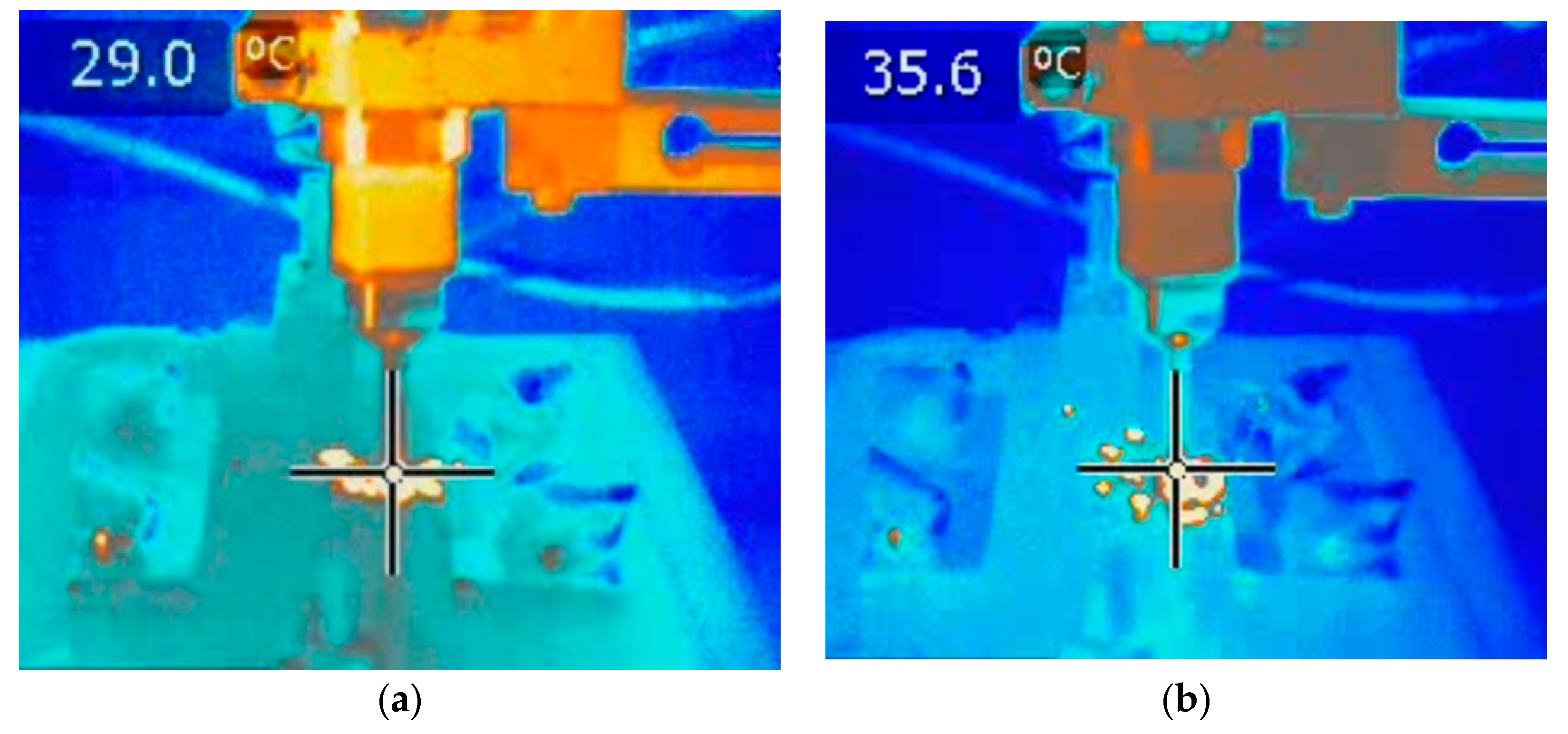
Comparing the times of the thermal imaging results and the times for the spindle speed drops, it can be determined that the heat spikes seen in the wet and dry drilling tests at around the 7 s mark are formed around the same time as the drops in spindle speed. After analysing the thermal imaging data, the drilling test can be split into four distinct parts; the process is shown in Figure 9.
Figure 9a shows when the drill bit initially starts to cut into the specimen and produce small chips. The spot temperature reading increases from room temperature of 24 °C to 29.0 °C. Figure 9b shows a rapid increase in temperature and, according to the spindle speed graphs, a decrease in spindle speed where the drill bit is snagging in the composite. Figure 9c shows where the drill bit either fails for the 1700 rpm test and dry 2100 rpm test, or the drill bit overcomes the snag with the expulsion of hot chip material and continues to drill into the composite. The final part is shown in Figure 9d where the drill bit then continues to drill through the rest of the composite unhindered.
5. Conclusions
Applying synthetic biodegradable oil directly to the drill bit tip area whilst drilling carbon fibre composites minimises the friction between the cutting edge and sample and hence minimises the reduction in spindle speed compared to dry drilling. The experimental data shows that the minimum drop in spindle speed whilst drilling with an oil mist (1.3%) is lower than drilling without the use of oil (17%).
The maximum drilling force results recorded by the load cell also agree that the oil reduces friction; every specimen tested with lubricating oil had a lower maximum drilling force exerted on the drill bit than the dry drilling experiments. The higher drilling force experienced by dry drilling could have also potentially increased the risk of causing delaminations within the composite.
Dry drilling caused more stoppages of the drill bit, failing at 1700 rpm and 2100 rpm, whereas the oil mist drilling only failed to drill through the carbon composite plate at 1700 rpm. Many companies programme a pecking action into their drilling machines because this action allows for the tool and workpiece to cool momentarily and clear any blockages that might be building up between the tool and the worked material.
Drilling with synthetic oil reduces the heat build-up in the composite compared to dry drilling. Additionally, expelled chips (cut material) are also removed by the drill bit flutes during drilling helped to reduce the overall temperatures experienced by the composite.
Author Contributions
Corydon M. J. Morrell and Paul R. Hampson conceived and wrote the paper; Corydon M. J. Morrell performed the experiment and analyzed the data; Paul R. Hampson supervised the experimental study, analyzed the results, and conducted the final editing of the paper.
Conflicts of Interest
The authors declare no conflict of interest.
References
- Abrate, S.; Walton, D. Machining of composite materials. Part I: Traditional methods. Compos. Manuf. 1992, 3, 75–83. [Google Scholar] [CrossRef]
- Persson, E.; Eriksson, I.; Zackrisson, L. Effects of hole machining defects on strength and fatigue life of composite laminates. Compos. A Appl. Sci. Manuf. 1997, 28, 141–151. [Google Scholar] [CrossRef]
- Mazumdar, S. Composites Manufacturing: Materials, Product, and Process Engineering, 1st ed.; CRC Press: Boca Raton, FL, USA, 2001. [Google Scholar]
- Lazar, M.-B.; Xirouchakis, P. Experimental analysis of drilling fiber reinforced composites. Int. J. Mach. Tools Manuf. 2011, 51, 937–946. [Google Scholar] [CrossRef]
- Phadnis, V.A.; Makhdum, F.; Roy, A.; Silberschmidt, V.V. Drilling in carbon/epoxy composites: Experimental investigations and finite element implementation. Compos. A Appl. Sci. Manuf. 2011, 47, 41–51. [Google Scholar] [CrossRef] [Green Version]
- Lees, R.; Dell’Anno, G. Effect of water immersion on the interlaminar and flexural performance of low cost liquid resin infused carbon fabric composites. Compos. B Eng. 2011, 43, 1368–1373. [Google Scholar]
- Zafar, A.; Bertocco, F.; Schjødt-Thomsen, J.; Rauhe, J.C.M. Investigation of the long term effects of moisture on carbon fibre and epoxy matrix composites. Compos. Sci. Technol. 2012, 72, 656–666. [Google Scholar] [CrossRef]
- Chen, W.-C. Some experimental investigations in the drilling of carbon fiber-reinforced plastic (CFRP) composite laminates. Int. J. Mach. Tools Manuf. 1997, 37, 1097–1108. [Google Scholar] [CrossRef]
- Abrão, A.M.; Faria, P.E.; Campos Rubio, J.C.; Reis, P.; Paulo Davim, J. Drilling of fiber reinforced plastics: A review. J. Mater. Process. Technol. 2007, 186, 1–7. [Google Scholar] [CrossRef]
- Liu, D.; Tang, Y.; Cong, W.L. A review of mechanical drilling for composite laminates. Compos. Struct. 2012, 94, 1265–1279. [Google Scholar] [CrossRef]
- TenCate Advanced Composites. TenCate E726 Product Datasheet; TenCate Advanced Composites Limited: Nottingham, UK, 2013. [Google Scholar]
Figure 1.
Delaminations caused by drilling: (a) ply peeling; (b) ply ‘push through’ (adapted from [2]).
Figure 1.
Delaminations caused by drilling: (a) ply peeling; (b) ply ‘push through’ (adapted from [2]).
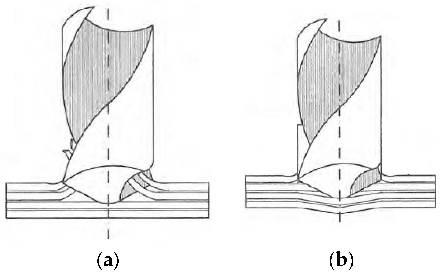
Figure 2.
Nachi SC06F-02 robotic arm.

Figure 3.
Airbrush attached to robot arm wrist.
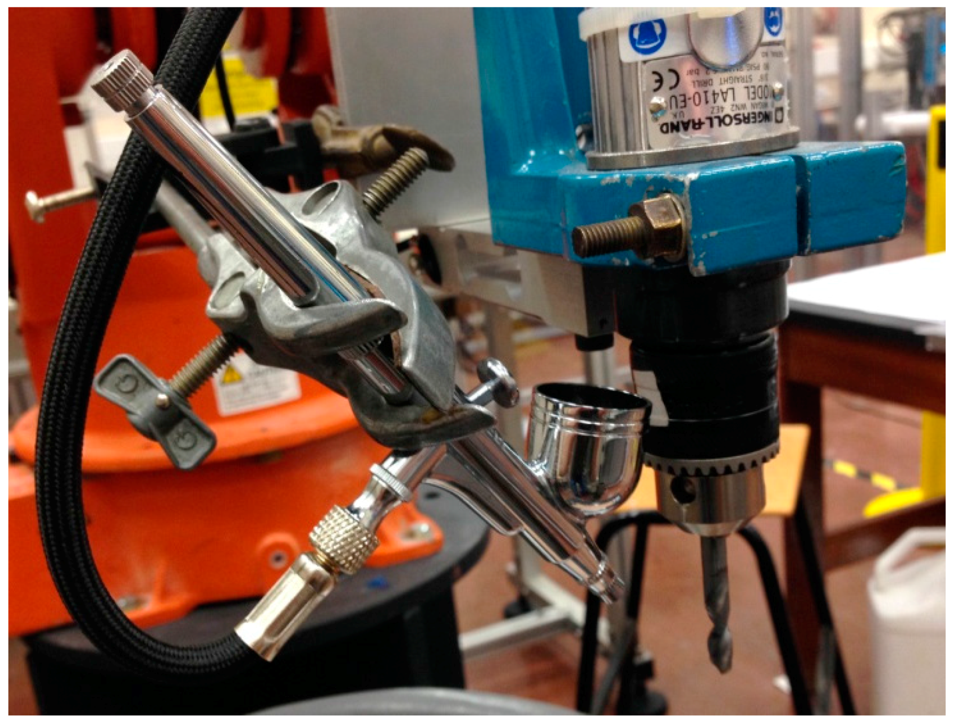
Figure 4.
Experimental apparatus.
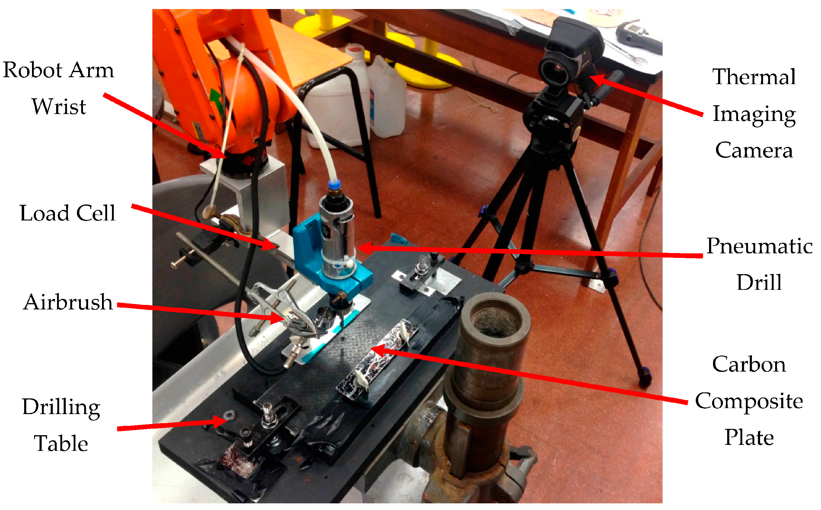
Figure 5.
Wet and dry comparisons for initial spindle speeds of (a) 1700, (b) 2100, (c) 2400, and (d) 2750 rpm.
Figure 5.
Wet and dry comparisons for initial spindle speeds of (a) 1700, (b) 2100, (c) 2400, and (d) 2750 rpm.
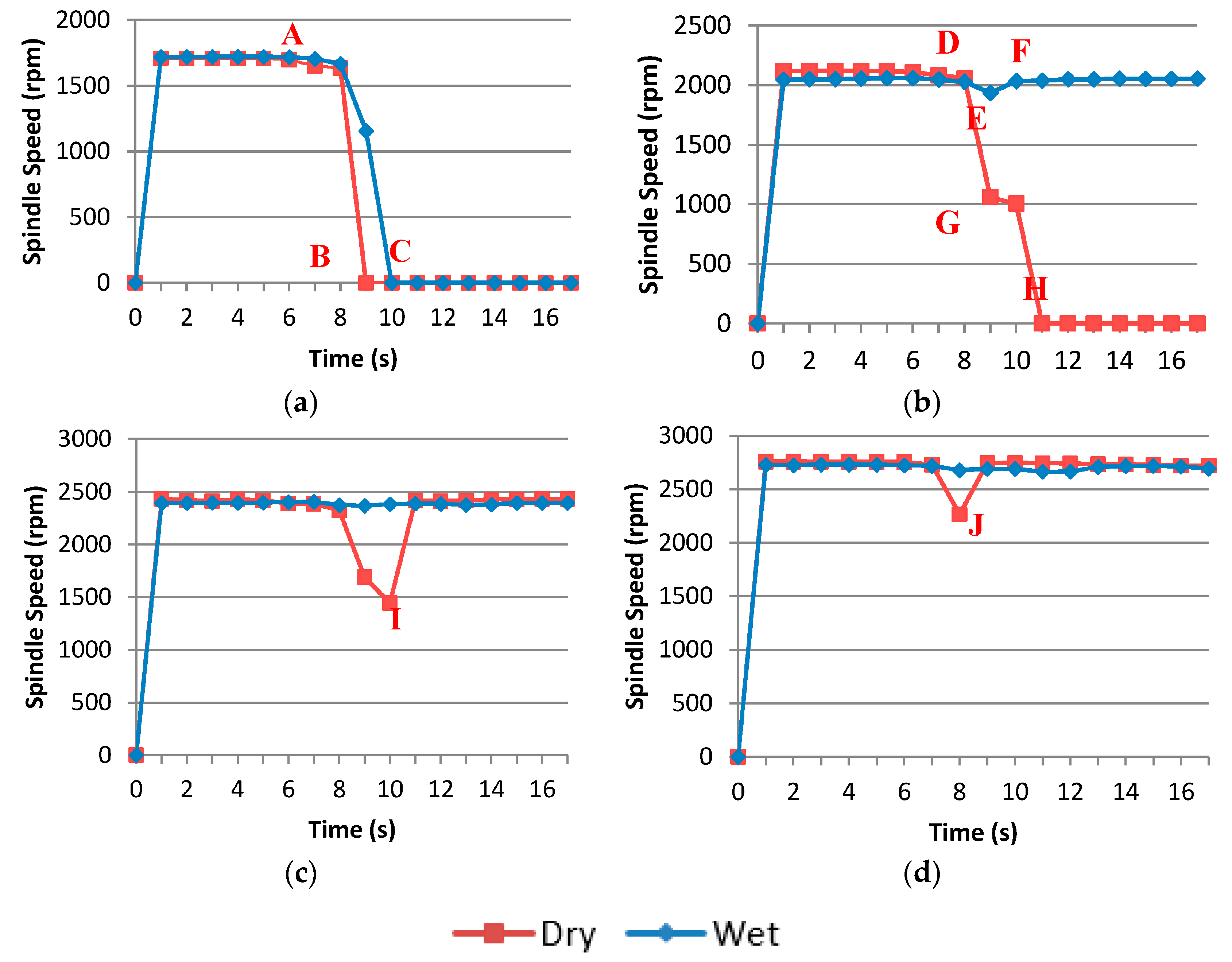
Figure 6.
Maximum drilling force.

Figure 7.
Wet and dry drilling temperature comparisons for initial spindle speeds of (a) 1700, (b) 2100, (c) 2400, and (d) 2750 rpm.
Figure 7.
Wet and dry drilling temperature comparisons for initial spindle speeds of (a) 1700, (b) 2100, (c) 2400, and (d) 2750 rpm.

Figure 8.
Peak drilling temperatures.
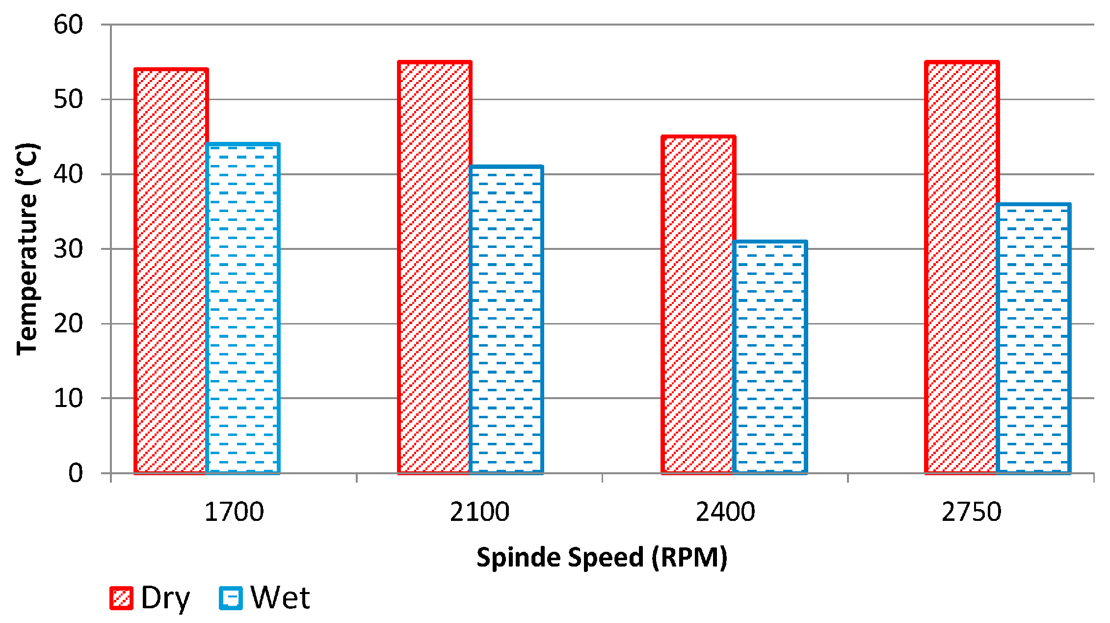
Figure 9.
Thermal images: (a) view of initial cutting; (b) drill bit snagging; (c) drill bit overcoming the snag; (d) drilling post-snag.
Figure 9.
Thermal images: (a) view of initial cutting; (b) drill bit snagging; (c) drill bit overcoming the snag; (d) drilling post-snag.


Table 1.
Lubricool Technical Data.
| Property | Value |
|---|---|
| Density at 20 °C | 0.865 g/cm3 |
| Viscosity at 40 °C | 8 mm2/s |
| Flash Point | >180 °C |
| Freezing point | <−30 °C |
Table 2.
Spindle speed percentage drops.
| Spindle Speed (rpm) | Percentage Drops | |
|---|---|---|
| Dry | Wet | |
| 1750 | 100% | 100% |
| 2100 | 100% | 8% |
| 2400 | 40% | 1.3% |
| 2750 | 17% | 1.4% |
© 2018 by the authors. Licensee MDPI, Basel, Switzerland. This article is an open access article distributed under the terms and conditions of the Creative Commons Attribution (CC BY) license (http://creativecommons.org/licenses/by/4.0/).
Share and Cite
MDPI and ACS Style
Morrell, C.M.J.; Hampson, P.R. Pneumatically Powered Drilling of Carbon Fibre Composites Using Synthetic Biodegradable Lubricating Oil: An Experimental Study. Aerospace 2018, 5, 9. https://doi.org/10.3390/aerospace5010009
AMA Style
Morrell CMJ, Hampson PR. Pneumatically Powered Drilling of Carbon Fibre Composites Using Synthetic Biodegradable Lubricating Oil: An Experimental Study. Aerospace. 2018; 5(1):9. https://doi.org/10.3390/aerospace5010009
Chicago/Turabian StyleMorrell, Corydon M. J., and Paul R. Hampson. 2018. "Pneumatically Powered Drilling of Carbon Fibre Composites Using Synthetic Biodegradable Lubricating Oil: An Experimental Study" Aerospace 5, no. 1: 9. https://doi.org/10.3390/aerospace5010009
Note that from the first issue of 2016, this journal uses article numbers instead of page numbers. See further details here.