Flexural Properties of Wet-Laid Hybrid Nonwoven Recycled Carbon and Flax Fibre Composites in Poly-Lactic Acid Matrix


1
School of Materials, The University of Manchester, Manchester M13 9PL, UK
2
Aerospace Research Institute, The University of Manchester, Manchester M13 9PL, UK
*
Author to whom correspondence should be addressed.
Aerospace 2018, 5(4), 120; https://doi.org/10.3390/aerospace5040120
Submission received: 3 September 2018
/
Revised: 31 October 2018
/
Accepted: 5 November 2018
/
Published: 15 November 2018
(This article belongs to the Special Issue ECO-COMPASS: Ecological and Multifunctional Composites for Application in Aircraft Interior and Secondary Structures)
Abstract
:Recycling carbon fibre is crucial in the reduction of waste from the increasing use of carbon fibre reinforced composites in industry. The reclaimed fibres, however, are usually short and discontinuous as opposed to the continuous virgin carbon fibre. In this work, short recycled carbon fibres (rCF) were mixed with flax and poly-lactic acid (PLA) fibres acting as the matrix to form nonwoven mats through wet-laying. The mats were compression moulded to produce composites with different ratios of rCF and flax fibre in the PLA matrix. Their flexural behaviour was examined through three-point-bending tests, and their morphological properties were characterised with scanning electron and optical microscopes. Experimental data showed that the flexural properties increased with higher rCF content, with the maximum being a flexural modulus of approximately 14 GPa and flexural strength of 203 MPa with a fibre volume fraction of 75% rCF and 25% flax fibre. The intimate mixing of the fibres contributed to a lesser reduction of flexural properties when increasing the flax fibre content.
1. Introduction
Carbon fibres (CF) are the preferred reinforcement material for polymer composites because they combine high strength and low weight compared to metallic or ceramic fibres [1]. The global demand for CF rose from 33,000 t in 2010 to 72,000 t in 2017 and is expected to grow at a rate of 9–12% for the next five years [2]. This increase of CF products comes with the increasing levels of waste resulting from expired prepregs, production cut-offs, testing materials, and end-of-life components from the aeronautics, automotive, and wind industries [3].
Due to the energy-intensive manufacturing of virgin CF [4], it also becomes more economical to recover and reuse CF. In the ideal case, recycled carbon fibres (rCF) would replace virgin fibres to save more energy and reduce production cost. However, fibre damage and resin residues from the recycling process decreases the fibre tensile strength to around 80% of the virgin fibres, depending on the recycling method, through thermal, mechanical, and chemical recycling treatments [5,6,7]. For mechanical recycling, the composites are crushed and sieved, which results in a powdered form that can be further used for injection moulding. In chemical recycling, the matrix is removed through different solvents, while thermal methods such as pyrolysis or the fluidised-bed process utilise heat energy. Pyrolysis is the most widespread method, but the fibres reclaimed by this process are commonly contaminated with char residues from the matrix which can degrade the fibre properties [7].
After the recycling procedure, the majority of the rCF comes in a short and discontinuous form with the length of the fibres ranging from 0.1 mm to 60 mm [5,7].
One way to further process these short rCF could be the conversion into nonwovens. Nonwovens are a type of fabric in which the fibres are bonded by thermal, mechanical, or chemical treatments [8]. Since they do not require yarn, short fibres can be used. For rCF, wet-laying would be suitable for manufacturing the nonwoven mat. This method is derived from the paper-making process in which the fibres are dispersed in an aqueous solution. The fibre slurry is deposited on a wire screen to drain the liquid, leaving the fibres to form a web. This process is suitable for almost all fibres [9] and is more gentle towards the fibres in comparison to carding, especially for more brittle fibres such as carbon, which tend to break into shorter lengths during the carding operation [10]. In addition, the wet medium also provides a safer environment in the manufacturing process since rCF reclaimed by pyrolysis can contain very fine carbon particles that could contaminate the air and equipment [11,12].
The disadvantages for the wet-laying process are the relatively low thickness of the resulting rCF mats and the higher consolidation pressure needed to adjust the composite thickness and increase the fibre volume fraction [13,14].
In the effort to compensate for the brittle nature of the rCF, hybridisation with natural fibres such as flax can be considered. The term “hybridisation” refers to the combination of two or more fibres inside a matrix. Oftentimes, natural fibre and synthetic fibre are chosen in order to achieve a synergetic effect on the composite’s properties [15]. Flax is one of the strongest natural fibres and is already used in a variety of composites [16,17]. With a tensile strength of 1.3 GPa and a Young’s modulus of 54 GPa, its properties are comparable to glass fibres [18,19]. CF are superior in strength, with a tensile strength of 3–5 GPa, but they exhibit brittle behaviour because of their high modulus of 250–700 GPa [20]. In a hybrid, the CF would provide strength while flax balances the inherent brittleness of CF. CF/flax hybrids are already used for sporting goods because of their combined strength and damping properties since the damping coefficient of composites reinforced by woven flax can be up to four times higher than the ones reinforced by carbon only [16,21].
Much of the work reported in the literature about hybrid CF/flax composites [21,22,23,24,25] has been focused on the plies of woven fabric from continuous virgin CF and long flax fibres rather than nonwoven recycled short fibres as proposed in this work. Few studies have examined the wet-laying of short fibre composites with either flax fibres [26,27,28,29,30] or rCF [11,12,13,31,32]. Recently, Longana et al. [33] have investigated a rCF/flax hybrid manufactured through a water-assisted fibre alignment method that was successfully used with short rCF and rCF/glass fibre hybrids [34,35]. The blending of both fibre types could potentially decrease the tendency for catastrophic delamination as the mixing is more intimate, which can enhance the hybrid’s properties [36].
In this research, short fibre rCF/flax composites were produced using wet-laying. To maximize the intermixing of the rCF/flax fibres for improved hybrid properties, the rCF, flax, and the poly-lactic acid (PLA) matrix fibres were dispersed together during the wet-laying process. The different fibre ratios were characterised through three-point-bending, scanning electron microscopy, and optical microscopy to optimise the processing parameters for future manufacturing.
2. Materials and Methods
2.1. Materials
Recycled CF and flax fibres were used as the reinforcement material, while the PLA in fibre form was the matrix constituent. CF reclaimed by pyrolysis, unsized, and chopped to the length of 12 mm with the diameter of 6–8 µm were purchased from ELG Carbon Fibre Ltd. (Coseley, UK). Scutched flax fibres in 10 mm lengths were supplied by FRD (Rosières-près-Troyes, France). For the matrix material, PLA slivers from Sirdar Spinning Ltd. (Wakefield, UK) were cut into 10 mm long segments.
2.2. Nonwoven Formation
Fibres of 2 g in weight were dispersed in 2 litres of water through a paper pulp disintegrator for 10,000 revolutions at a speed of 3000 revolutions per minute.
The dispersion was poured with additional water into a Handsheet Former manufactured by Mavis Engineering Ltd. (London, UK). This apparatus consisted of a base with a porous mesh that was connected to a drain pipe. A metallic cylinder closed the top which was filled with the fibre dispersion. Through draining the water, the fibres collected on the net at the bottom and formed a circular mat with a diameter of 16 cm. These were blotted with filter papers and pressed with a couch roll to extract excess water and smooth out the surface. Afterwards, the mats were left to dry by air convection for 24 h at room temperature.
Five different samples were made with the volume ratios of rCF and flax fibre as presented in Table 1.
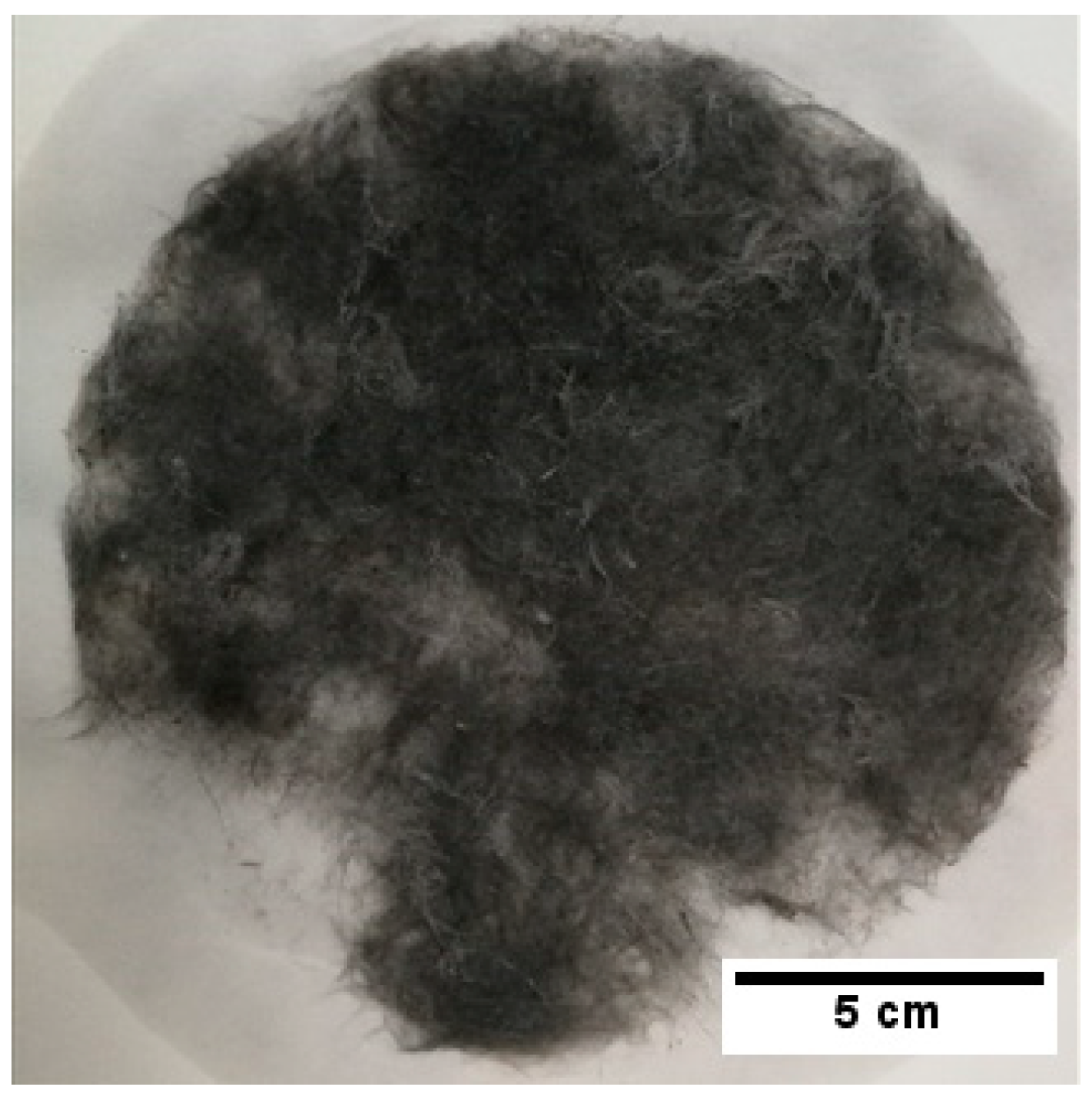
For the dispersion of the fibres, all components of the mat had to be added in the desired proportions. To keep the grammage of the fabric constant at 100 g/m2, 2 g of fibres were used per mat in the form of a disc with a 16 cm diameter. The target fibre volume fraction for the final composite was chosen to be 30% since previous work [13,27,28,30] reported lowered mechanical properties at higher fibre fractions due to fibre breakage. Assuming ( matrix volume fraction), Equation (1) can be used to determine the corresponding weight composition of the fibres. One layer of sample 2 with 75% rCF and 25% flax is shown in Figure 1.
where
- = Density of fibre [g/cm3]
- = Density of matrix [g/cm3]
- = Weight of fibres [g]
- = Weight of matrix [g]
Table 2 shows the fibre weights used for the mat formation of each sample calculated with , , and .
2.3. Composite Fabrication
Several layers of the nonwoven mats with the same fibre ratio were stacked between two 0.2 mm thick PTFE (Polytetrafluorethylene) sheets before being placed inside the hot press. The PTFE prevented the composite from adhering to the steel plates of the machine. Upon closing the press, a 2 bar pressure was applied and the plates were heated at a rate of ca. 25 °C/min until a temperature of 160 °C was reached. This temperature was kept for 10 min while maintaining the pressure, after which the plates were cooled to 50 °C and the composite sample was removed. The densities of the composites were determined through the water immersion method and compared to their theoretical densities to calculate the void content. In Table 3, the number of layers used to obtain the target thickness of 2 mm along with the density values are presented.
2.4. Optical Microscopy
Cut-outs in the dimension of 1 × 2 cm2 from each composite were cast in an epoxy resin and cured at room temperature for 24 h. The prepared specimens were ground and polished until the surface and the cross-section were sufficiently smooth to be viewed under edge-lighting of the Keyence VHX-5000 microscope. This technique allowed better distinguishing of the brighter reflective fibres and voids in the PLA matrix that appeared darker in the optical image.
2.5. Flexural Tests
Three-point bending tests were performed according to BS EN ISO 14125 to determine the flexural behaviour. Five specimens of each sample were tested on an Instron model 5969 with a 10 kN load cell at a cross-head speed of 1 mm/min. The deflection was given by the displacement of the central loading member, and the specimen dimensions were 60 × 25 mm2 with a span ratio of 1:20.
The flexural stress was determined by the following equation (Equation (2)):
where
- = flexural stress [MPa]
- F = load [N]
- L = length of span [mm]
- b = width of the specimen [mm]
- h = thickness of the specimen [mm]
Flexural modulus was obtained by:
where
- = flexural modulus of elasticity [MPa]
- = central deflection [mm]
Flexural strain was calculated as:
2.6. Scanning Electron Microscopy
After the flexural tests were performed, the specimens were viewed under the scanning electron microscope (SEM) in order to assess surface damage. The specimens were sputter coated with gold and examined with the Zeiss EVO60 at 8 kV.
3. Results and Discussion
3.1. Morphological Observations
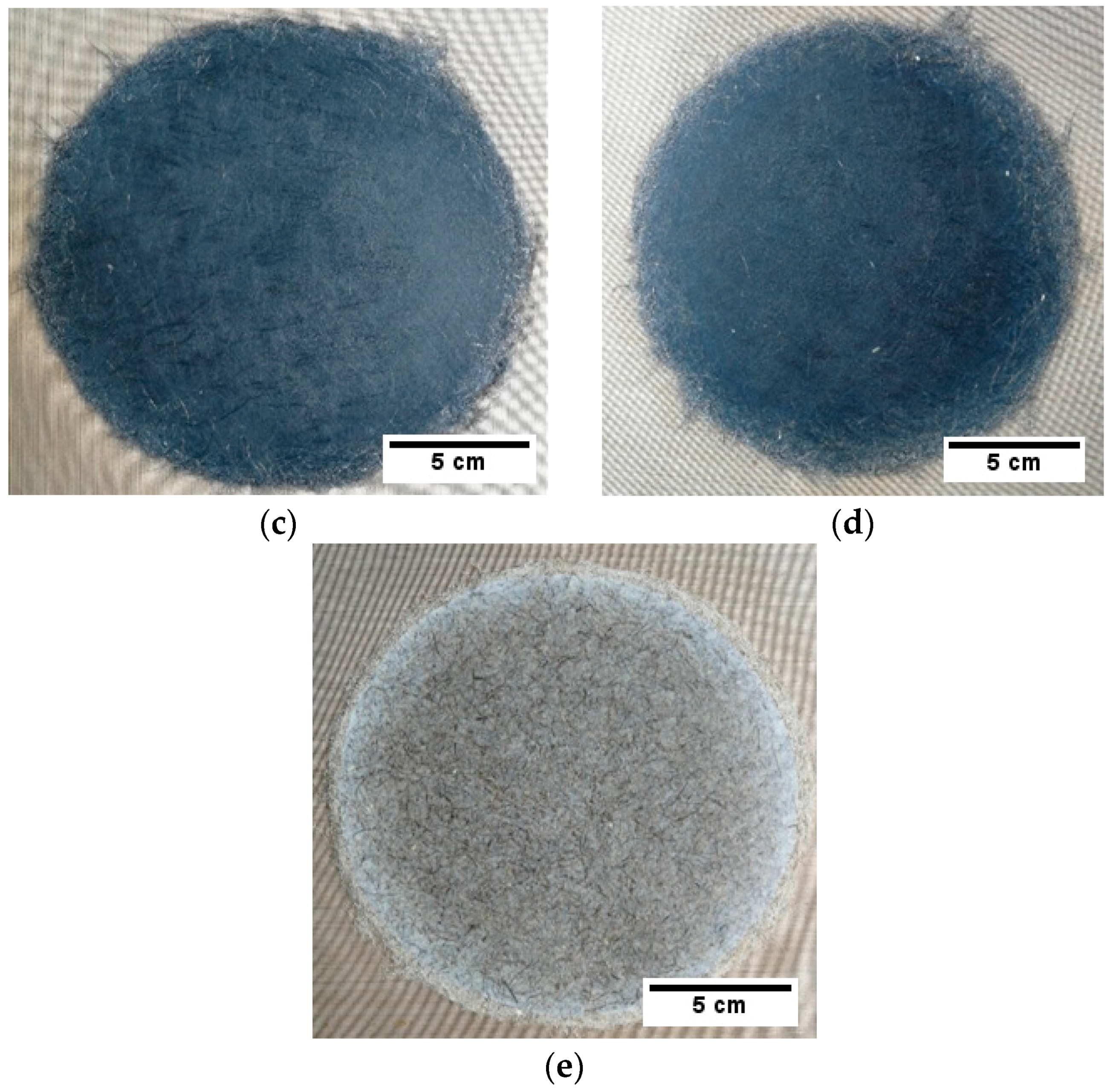
The finished composite samples are depicted in Figure 2a–e. Figure 1 shows a single layer of the nonwoven mat. Although the single layers produced showed variations in areal density, by stacking multiple plies, the variations were evened out and ultimately formed a homogenous composite with a smooth surface.
Unlike flax fibres, rCF does not contain a collapsible lumen nor does it change its shape when compressed. Therefore, fewer plies were needed to achieve an overall thickness of 2 mm for the samples with higher rCF content. Another effect of the lower compactability of rCF was the tapered edge of the composites with high rCF content, prominently visible in Figure 2a, as the rCF spread out when consolidated in the hot press. Furthermore, cellulose-based fibres like flax form inter-fibre hydrogen bonds after drying from wet-laying, which contributed to the shape retention in the samples with higher flax fibre content, as seen in Figure 2b–e.
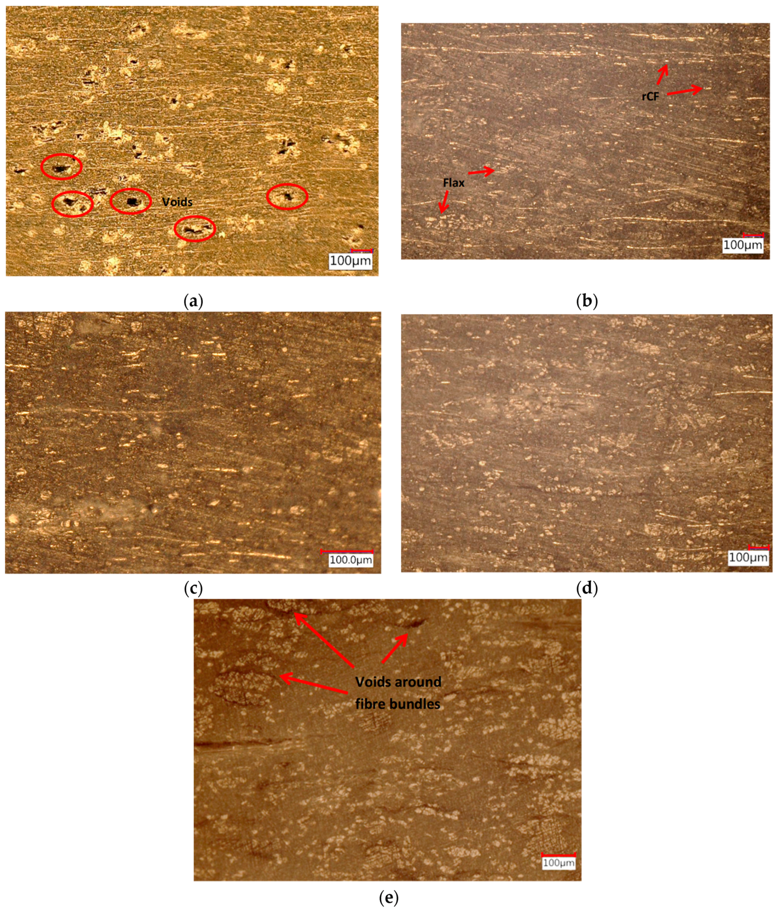
3.2. Analysis of the Cross-Section and Void Content
In Figure 3, the optical micrographs of the composites’ cross-sections are presented. For sample 1 (Figure 3a), the view under the microscope revealed several voids inside the composite which explained the low density measured compared to the theoretical value. These almost round voids were in the size range of 10–100 µm and randomly distributed throughout the cross-section. The bright edges of the voids and the other bright spots were caused by the polished congregations of PLA which also reflected the light. This indicated that the 2 bar applied pressure was not enough to obtain sufficiently densely packed fibres for the target composite fibre volume fraction of 30% with a 100% rCF content.
Samples 2, 3, and 4 (Figure 3b–d) showed no visible voids and a fairly homogeneous distribution of rCF and flax fibres. The density measurements showed slightly elevated void contents for samples 2 and 4 at 9.1% and 11.2%, respectively, in comparison to samples 3 and 5 with 6.0% and 7.7%. They could be caused by increased gas formation from the PLA during the heating process on the hot press [37]. The higher void content from samples 2 and 4 were not detected through the microscope since the cross-section examined only represented a small part of the overall composite specimen and the voids might be present in other areas.
However, increasing the flax fibre content seemed to reduce the void content when compared to sample 1 by achieving the right amount of compactability for the PLA to fill in the space between the fibres and form a continuous solid phase. Replacing 25 vol % rCF with flax, e.g., sample 2 in Figure 3b, was enough to obtain the target fibre content without further increasing the pressure.
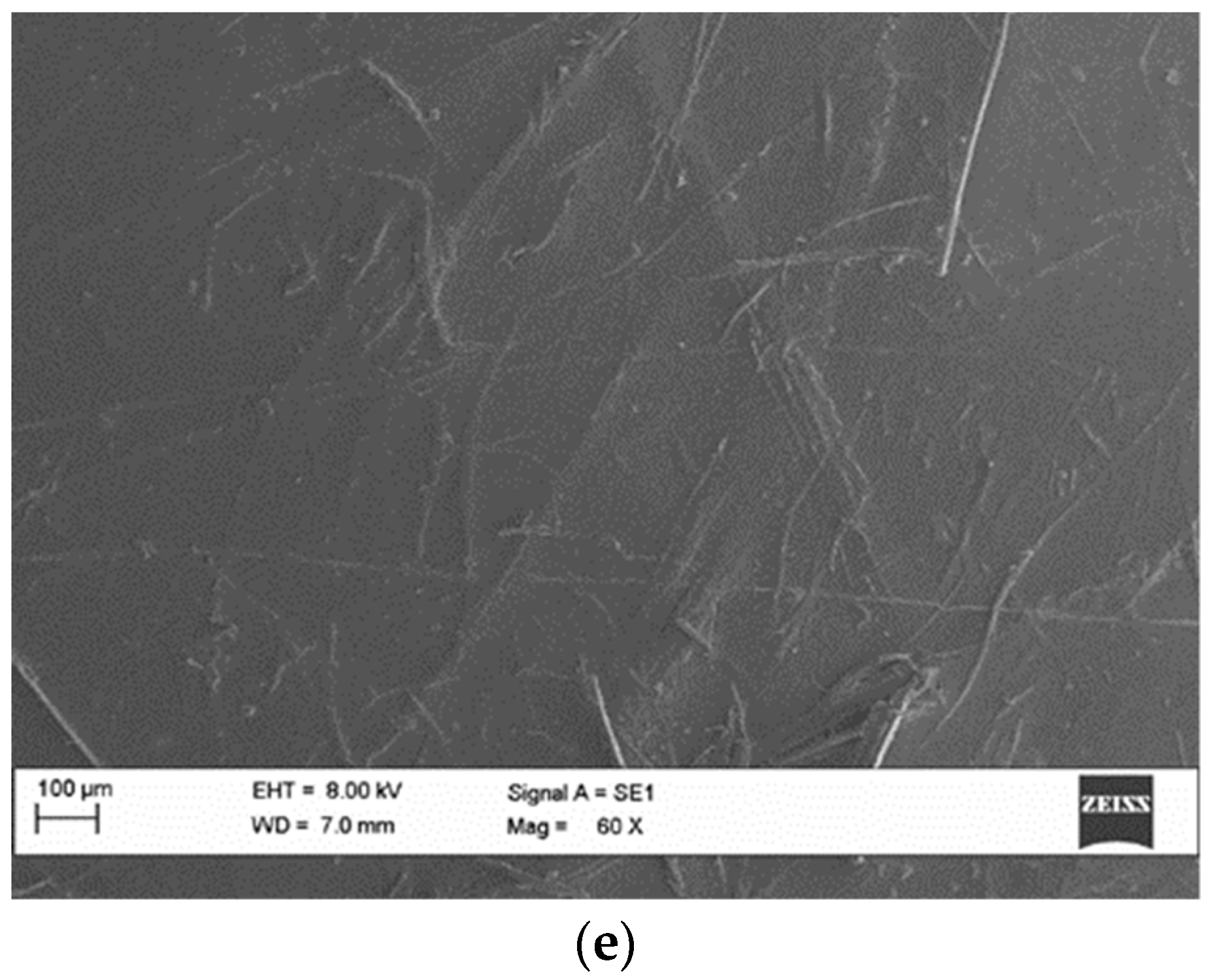
In sample 5, with 100% flax fibres (Figure 2e), thin voids were seen mostly surrounding tightly packed fibre bundles. This suggests that the fibre bundles were packed too closely for the PLA to wet the fibres. The elongated shape of the voids could potentially contribute to premature failure by initiating matrix cracking from the ends of the voids [19].
Generally, nonwoven composites will have higher void content compared to woven or unidirectional composites because the random orientation of the fibres can impede matrix flow or entrap air [38]. Furthermore, the hollow lumen inside natural fibres such as flax also act as a void and increase the void content of the composite [37].
3.3. Flexural Tests
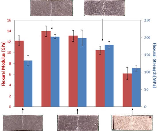
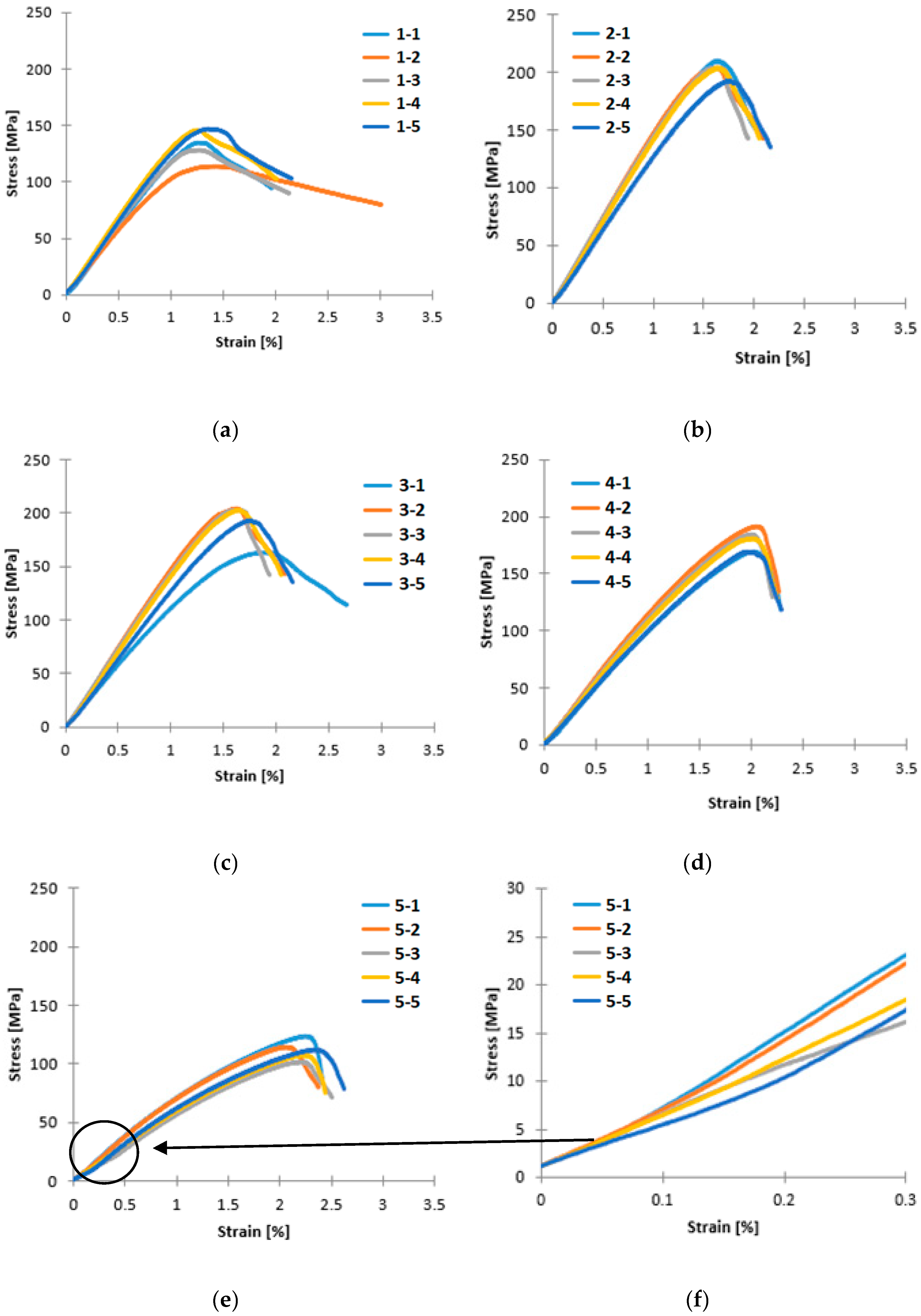
The stress–strain curves obtained from the flexural test are plotted in Figure 4a–e. Table 4 presents the values for the flexural modulus, flexural strength, and strain to failure. The flexural modulus and flexural strength of the tested samples are also displayed in Figure 5.
Below 0.3% strain, the stress–strain response showed a small crimp region for all curves. A magnification of the area up 0.3% strain for the stress–strain curve of sample 5 can be seen in Figure 4f. The crimp could be attributed to the elastic deformation of the PLA matrix. Its polymer strands were stretched and absorbed some of the stress as the cross-head touched the outermost layers at low strains. Afterwards, the curve became more linear with the increasing rCF content. The addition of flax fibres contributed to the non-linear deformation in the composite past the point of ultimate strength at which the matrix fails, and further softening of the curves could be seen for samples 1, 2, and 3 (Figure 4a–c) which corresponded to breakages of rCF. Overall, by increasing the flax content, the composite’s ability to withstand higher strain was also increased due to the ductile behaviour of flax. Sample 1 seemed to break at a higher strain at failure on average because the high void content which introduced irregularities to the composite’s composition, resulting in variable flexural behaviour. Although sample 3 contained more flax than sample 2, they behaved similarly and failed at around 2% strain. Sample 4 failed at 2.3% strain and sample 5 had the highest strain to failure at 2.5%, since this was made entirely of flax fibres.
In general, the composites with higher rCF content had higher flexural modulus and strength. For this reason, sample 1 with 100% rCF as reinforcement was expected to exhibit the highest flexural properties. However, its flexural modulus of 12.20 GPa was below those of samples 2 and 3 with 13.98 GPa and 13.12 GPa, respectively. Moreover, the flexural strength of sample 1 at 133.77 MPa was the second lowest after sample 5 with 111.61 MPa which only used flax fibres as reinforcement. This could be explained by the numerous voids observed in the optical micrographs of sample 1. Because of the high void fraction, the load could not be completely transferred to the rCF so that the matrix and the rCF broke separately from each other. This caused the softening after the point of ultimate strength in the stress–strain curve in Figure 4a.
It was found that sample 2 had the highest average flexural strength of 202.61 MPa followed closely by sample 3 with 198.66 MPa. Between samples 2 and 3, the increase of flax fibre content only decreased the flexural strength by 2.1% and the flexural modulus by 6.2%, which was within the scatter of the measured data. Further reducing the rCF content to 25% in sample 4 resulted in a decrease of almost 10% in flexural strength and 20% in flexural modulus when compared to sample 3. From the perspective of sample 5, replacing 25 vol % of flax with rCF increased the flexural strength by 60% and the flexural modulus by 70%. Compared to the relevant literature, Le Guen et al. [21] showed a decrease of 34.2% in flexural strength of their woven CF/flax epoxy composite as the CF volume fraction was lowered from 58% to 26%. However, this is a different system with long fibres and separate plies. This suggests that with the better intermixing of rCF/flax, the higher flexural properties could be maintained over a wider range of rCF/flax ratios; the void content and overall quality of the fabricated specimen are vital.
3.4. Surface Morphology and Failure Assessment
SEM results revealed that in addition to the voids inside sample 1, it also had a porous surface. The surface images of each sample are shown in Figure 6. Although the optical micrographs suggest an even mixture of the fibres, from the images it appeared as if the rCF in the composites tended to accumulate on the outermost layers and leave a rougher surface, as seen in Figure 6a–c. In contrast, samples with higher flax fibre content gave the surface a smoother appearance (Figure 6e).
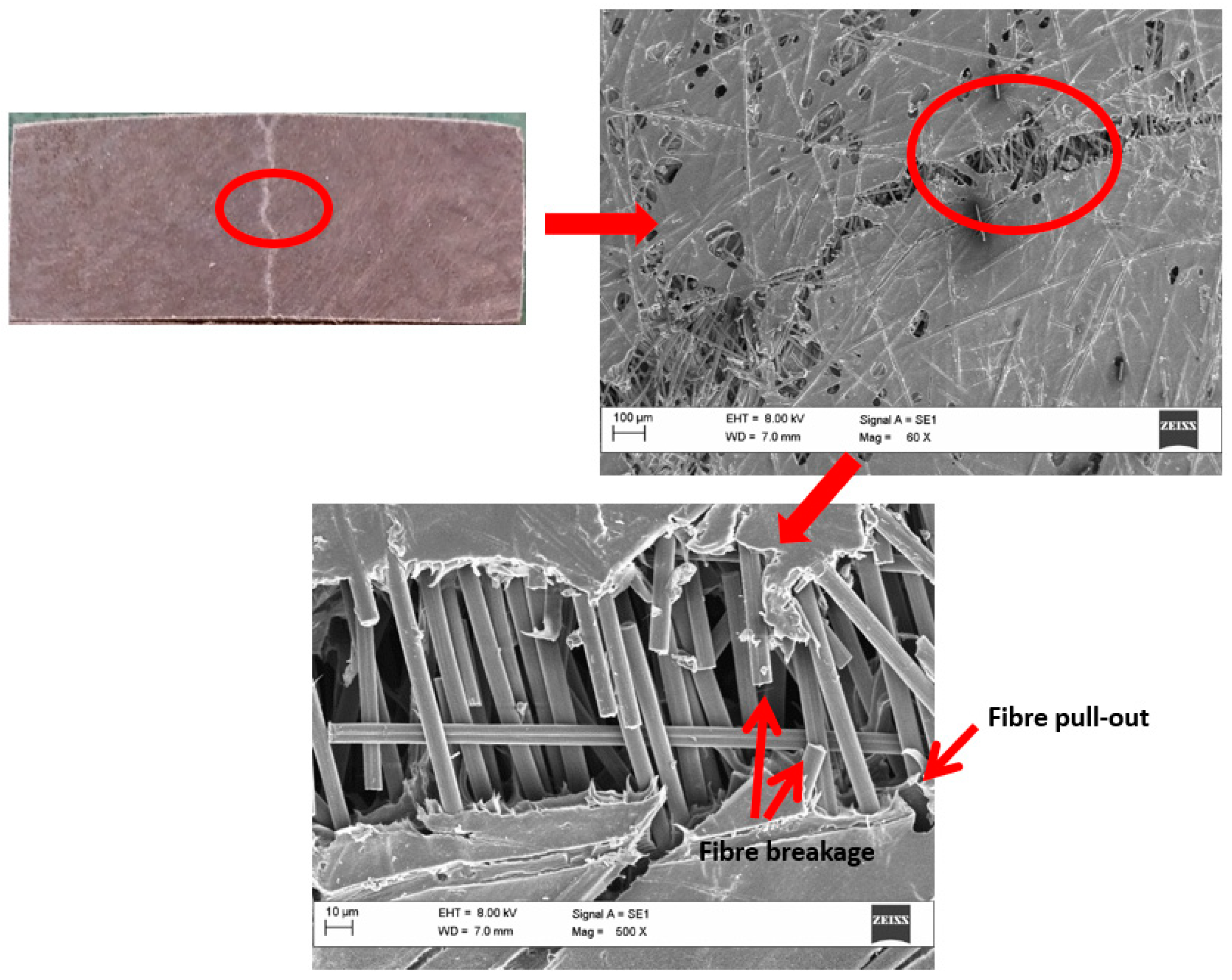
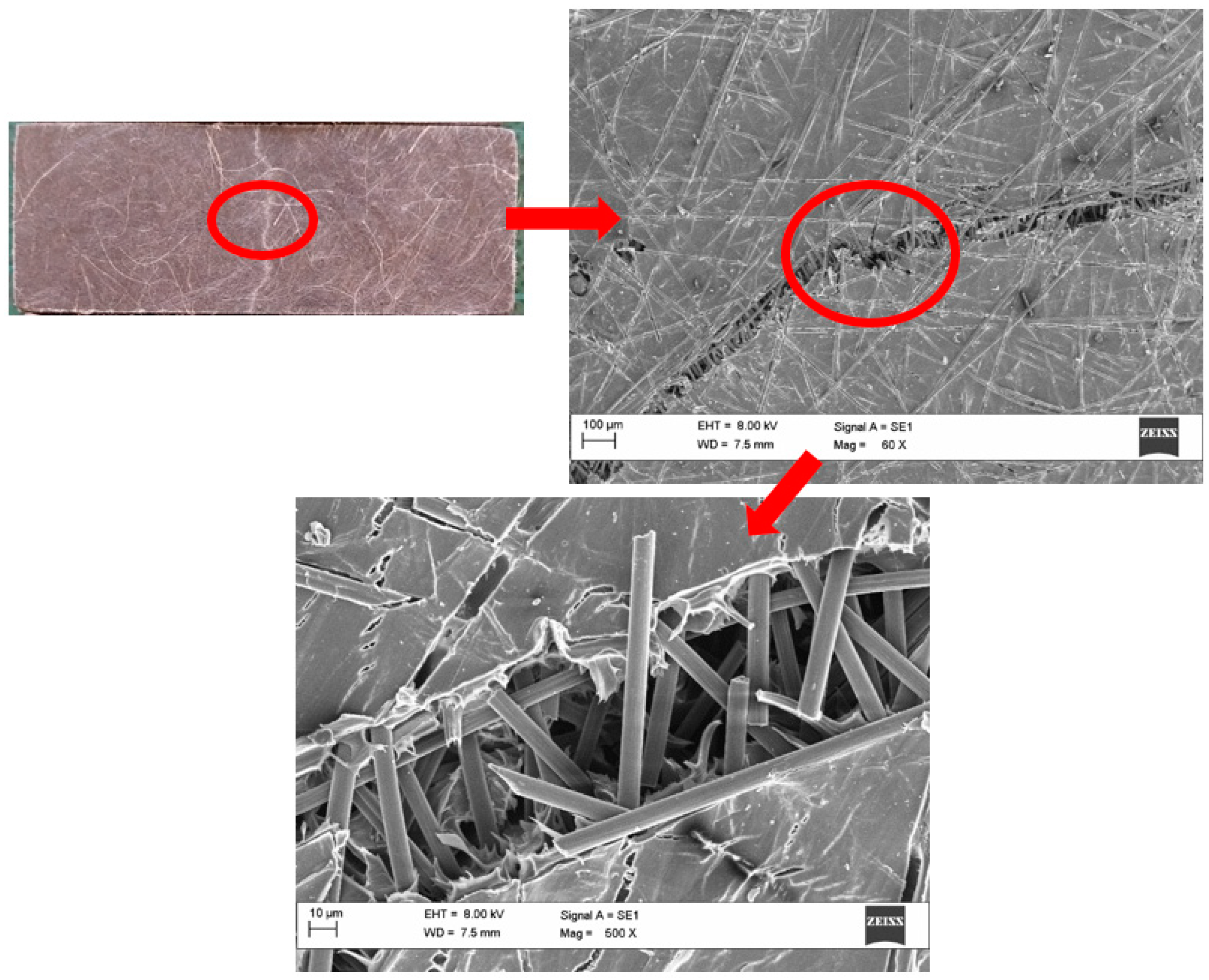
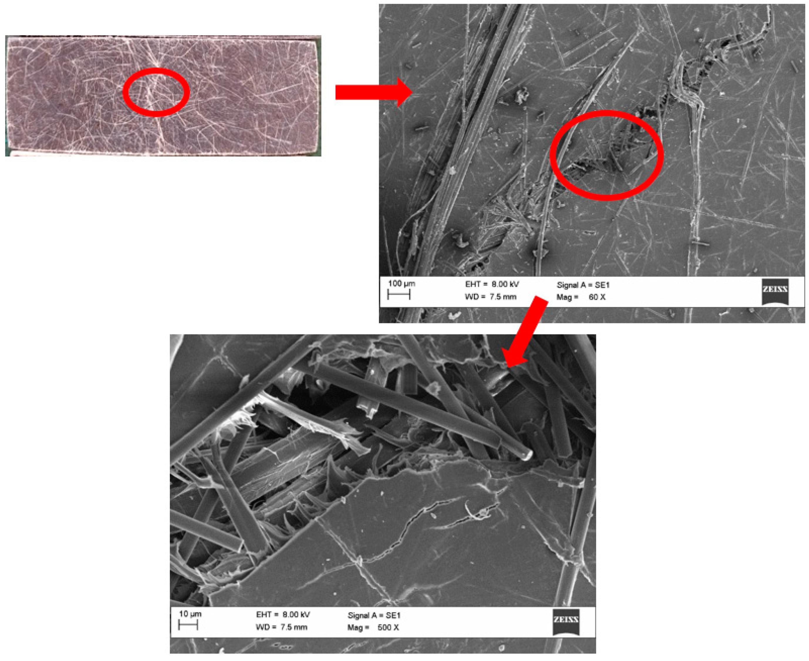
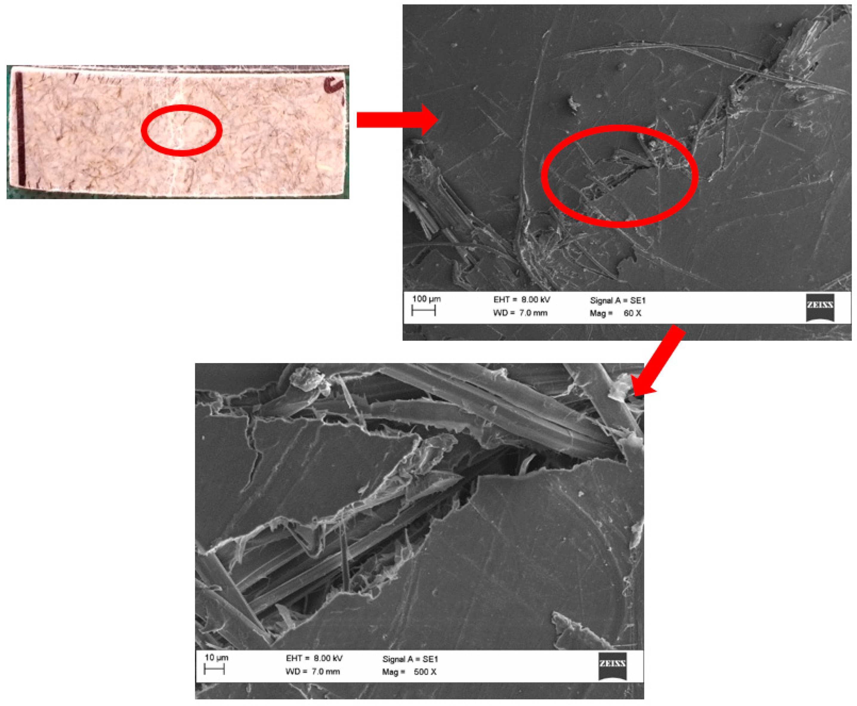
The main cause of failure was the excessive tensile stress at the bottom surface of the specimen which resulted in the breakage of the matrix. This failure mode contributed towards the low flexural properties of sample 1 as well, since the propagation of the crack was facilitated by the presence of voids and surface porosity that magnified local stresses. Fibre pull-out and breakage were also visible, especially for the rCF, which could be seen in Figure 7. Most of the rCF fibres beneath the crack were not coated by matrix material, also visible in Figure 7, suggesting that they were de-bonded from the PLA matrix due to poor adhesion. This led to poor interfacial strength and hence a less effective load transfer from the resin to the fibres, resulting in premature failure and hence lower flexural strength. The matrix crack in sample 2 (Figure 8) was similar in size and shape to the one observed in sample 1. Fibre pull-out and breakages of rCF could be detected, but without the surface porosity, higher load was needed to propagate the crack through the matrix, which was why the average flexural strength of sample 2 was higher when compared to sample 1.
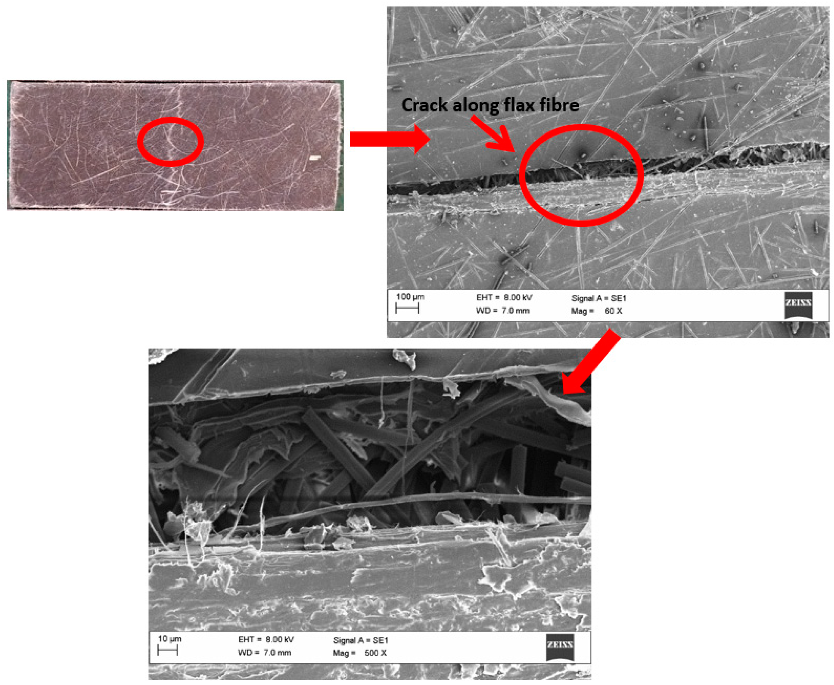
With higher flax content, more flax fibres were visible on the composite fracture surface. The flax fibres perpendicular to the direction of load could act as a crack initiator through de-bonding from the matrix, as seen in specimen 3-3 in Figure 9. Below the crack surface, flax fibres with matrix residue were visible which suggested better matrix adhesion. Specimen 4-3 in Figure 10 also had fibres on the surface; however, the fibres were not aligned in the direction of the crack and seemed to deflect it. It seemed as if the increase in flax fibre content decreased the rCF de-bonding from the matrix since the propagation of the crack appeared to be more winded and less prominent, e.g., in Figure 10 and Figure 11.
From the higher magnification images of the composites with rCF, it can be concluded that the matrix adhesion between rCF and PLA tended to be poorer in comparison to flax as pull-outs and breakages of the rCF were clean. The higher affinity between flax and PLA is explained through their hydrophilic nature and the ability to form hydrogen bonds with their abundance of polar groups in their structures. Meanwhile, rCF containing mostly nonpolar C–C bonds was not able to form lasting hydrogen bonds with PLA and parted from the matrix with less force. The better matrix combability also resulted in a smaller matrix crack, as seen when comparing samples 1 and 2 with high rCF content and a gap of 100 µm in the matrix in (Figure 7 and Figure 8) with sample 5 with 20 µm (Figure 11).
4. Conclusions
Short fibre hybrid composites were manufactured through wet-laying with different ratios of rCF and flax fibres, and their flexural behaviour and morphological structure were analysed. The composite with 75% rCF and 25% flax fibre showed the highest average flexural strength and modulus of 202.61 MPa and 13.98 GPa, respectively, followed closely by the sample with 50% rCF and 50% flax. The intimate mixing between rCF and flax fibre during the dispersing stage allowed for a lesser decrease of flexural properties as the flax fibre content increased. Surface porosity and void content in the 100% rCF composite induced during the fabrication process contributed to early matrix cracking initiation that led to fibre/matrix de-bonding and premature fibre failure in the form of breakage and fibre pull-out. Replacing 25% of the rCF content with flax helped to increase the compactability of the nonwoven, resulting in the lowering of the void content without increasing the pressure of the hot press. Furthermore, rCF showed poor matrix adhesion with PLA, and fibre treatments could be considered to increase the interfacial bond between matrix and fibres.
Author Contributions
Conceptualization and methodology, B.T. and H.G.; validation, C.S. and H.G.; investigation, B.T. and X.Y.; writing–original draft preparation, B.T. and X.Y.; writing–review and editing, B.T., C.S. and H.G.; supervision, C.S. and H.G.
Funding
This project received funding from The European Union’s Horizon 2020 research and innovation programme under grant agreement No. 690638.
Conflicts of Interest
The authors declare no conflict of interest.
References
- Bunsell, A.R. Fibres for composite reinforcement: Properties and microstructures. In Composite Reinforcements for Optimum Performance; Woodhead Publishing: Sawston, UK, 2011; pp. 3–31. ISBN 9781845699659. [Google Scholar]
- Kuehnel, M.; Kraus, T. The Global CFRP Market 2016. In Proceedings of the International Composites Congress (ICC), Düsseldorf, Germany, 28 November 2016. [Google Scholar]
- Pimenta, S.; Pinho, S.T. Recycling carbon fibre reinforced polymers for structural applications: Technology review and market outlook. Waste Manag. 2011, 31, 378–392. [Google Scholar] [CrossRef] [PubMed] [Green Version]
- Witik, R.A.; Teuscher, R.; Michaud, V.; Ludwig, C.; Månson, J.-A.E. Carbon fibre reinforced composite waste: An environmental assessment of recycling, energy recovery and landfilling. Compos. Part A Appl. Sci. Manuf. 2013, 49, 89–99. [Google Scholar] [CrossRef]
- Pimenta, S.; Pinho, S.T. Recycling of Carbon Fibers. In Handbook of Recycling: State-of-the-Art for Practitioners, Analysts, and Scientists; Worrell, E., Reuter, M.A., Eds.; Elsevier Inc.: Amsterdam, The Netherlands, 2014; pp. 269–283. ISBN 9780123965066. [Google Scholar]
- Pickering, S.J. Recycling technologies for thermoset composite materials—Current status. Compos. Part A Appl. Sci. Manuf. 2006, 37, 1206–1215. [Google Scholar] [CrossRef]
- Oliveux, G.; Dandy, L.O.; Leeke, G.A. Current status of recycling of fibre reinforced polymers: Review of technologies, reuse and resulting properties. Prog. Mater. Sci. 2015, 72, 61–99. [Google Scholar] [CrossRef]
- Russell, S.J. Handbook of Nonwovens; CRC Press: Boca Raton, FL, USA, 2006; ISBN 9781845691998. [Google Scholar]
- Pill, H.; Afflerbach, K. Wet Lay Method. In Nonwoven Fabrics; Wiley-VCH Verlag GmbH & Co. KGaA: Weinheim, Germany, 2004; pp. 237–267. [Google Scholar]
- Akonda, M.H.; Lawrence, C.A.; Weager, B.M. Recycled carbon fibre-reinforced polypropylene thermoplastic composites. Compos. Part A Appl. Sci. Manuf. 2012, 43, 79–86. [Google Scholar] [CrossRef]
- Giannadakis, K.; Szpieg, M.; Varna, J. Mechanical Performance of a Recycled Carbon Fibre/PP Composite. Exp. Mech. 2011, 51, 767–777. [Google Scholar] [CrossRef]
- Szpieg, M.; Wysocki, M.; Asp, L.E. Reuse of polymer materials and carbon fibres in novel engineering composite materials. Plast. Rubber Compos. 2009, 38, 419–425. [Google Scholar] [CrossRef]
- Shah, D.U.; Schubel, P.J. On recycled carbon fibre composites manufactured through a liquid composite moulding process. J. Reinf. Plast. Compos. 2016, 35, 533–540. [Google Scholar] [CrossRef]
- Turner, T.A.; Warrior, N.A.; Pickering, S.J. Development of high value moulding compounds from recycled carbon fibres. Plast. Rubber Compos. 2010, 39, 151–156. [Google Scholar] [CrossRef]
- Nunna, S.; Chandra, P.R.; Shrivastava, S.; Jalan, A. A review on mechanical behavior of natural fiber based hybrid composites. J. Reinf. Plast. Compos. 2012, 31, 759–769. [Google Scholar] [CrossRef]
- Pil, L.; Bensadoun, F.; Pariset, J.; Verpoest, I. Why are designers fascinated by flax and hemp fibre composites? Compos. Part A Appl. Sci. Manuf. 2016, 83, 193–205. [Google Scholar] [CrossRef]
- Yan, L.; Chouw, N.; Jayaraman, K. Flax fibre and its composites—A review. Compos. Part B Eng. 2014, 56, 296–317. [Google Scholar] [CrossRef]
- Baley, C. Analysis of the flax fibres tensile behaviour and analysis of the tensile stiffness increase. Compos. Part A Appl. Sci. Manuf. 2002, 33, 939–948. [Google Scholar] [CrossRef]
- Hull, D.; Clyne, T.W. An Introduction to Composite Materials; Cambridge University Press: Cambridge, UK, 1996; ISBN 9781139170130. [Google Scholar]
- Chung, D.D.L. Carbon Fiber Composites; Butterworth-Heinemann: Oxford, UK, 1994; ISBN 9780080500737. [Google Scholar]
- Le Guen, M.J.; Newman, R.H.; Fernyhough, A.; Emms, G.W.; Staiger, M.P. The damping–modulus relationship in flax–carbon fibre hybrid composites. Compos. Part B Eng. 2016, 89, 27–33. [Google Scholar] [CrossRef]
- Sarasini, F.; Tirillò, J.; D’Altilia, S.; Valente, T.; Santulli, C.; Touchard, F.; Chocinski-Arnault, L.; Mellier, D.; Lampani, L.; Gaudenzi, P. Damage tolerance of carbon/flax hybrid composites subjected to low velocity impact. Compos. Part B Eng. 2016, 91, 144–153. [Google Scholar] [CrossRef]
- Dhakal, H.N.; Zhang, Z.Y.; Guthrie, R.; MacMullen, J.; Bennett, N. Development of flax/carbon fibre hybrid composites for enhanced properties. Carbohydr. Polym. 2013, 96, 1–8. [Google Scholar] [CrossRef] [PubMed] [Green Version]
- Assarar, M.; Zouari, W.; Sabhi, H.; Ayad, R.; Berthelot, J.M. Evaluation of the damping of hybrid carbon-flax reinforced composites. Compos. Struct. 2015, 132, 148–154. [Google Scholar] [CrossRef]
- Fiore, V.; Valenza, A.; Di Bella, G. Mechanical behavior of carbon/flax hybrid composites for structural applications. J. Compos. Mater. 2012, 46, 2089–2096. [Google Scholar] [CrossRef] [Green Version]
- Bos, H.L.; Müssig, J.; van den Oever, M.J.A. Mechanical properties of short-flax-fibre reinforced compounds. Compos. Part A Appl. Sci. Manuf. 2006, 37, 1591–1604. [Google Scholar] [CrossRef]
- Bodros, E.; Pillin, I.; Montrelay, N.; Baley, C. Could biopolymers reinforced by randomly scattered flax fibre be used in structural applications? Compos. Sci. Technol. 2007, 67, 462–470. [Google Scholar] [CrossRef]
- Roussière, F.; Baley, C.; Godard, G.; Burr, D. Compressive and Tensile Behaviours of PLLA Matrix Composites Reinforced with Randomly Dispersed Flax Fibres. Appl. Compos. Mater. 2012, 19, 171–188. [Google Scholar] [CrossRef]
- Fages, E.; Cano, M.; Gironés, S.; Boronat, T.; Fenollar, O.; Balart, R. The use of wet-laid techniques to obtain flax nonwovens with different thermoplastic binding fibers for technical insulation applications. Text. Res. J. 2013, 83, 426–437. [Google Scholar] [CrossRef]
- Fages, E.; Gironés, S.; Sánchez-Nacher, L.; García-Sanoguera, D.; Balart, R. Use of wet-laid techniques to form flax-polypropylene nonwovens as base substrates for eco-friendly composites by using hot-press molding. Polym. Compos. 2012, 33, 253–261. [Google Scholar] [CrossRef]
- Wong, K.H.; Syed Mohammed, D.; Pickering, S.J.; Brooks, R. Effect of coupling agents on reinforcing potential of recycled carbon fibre for polypropylene composite. Compos. Sci. Technol. 2012, 72, 835–844. [Google Scholar] [CrossRef]
- Pickering, S.; Liu, Z.; Turner, T.; Wong, K. Applications for carbon fibre recovered from composites. IOP Conf. Ser. Mater. Sci. Eng. 2016, 139. [Google Scholar] [CrossRef]
- Longana, M.L.; Yu, H.; Aryal, P.; Potter, K.D. The High Performance Discontinuous Fibre (HiPerDiF) Method for Carbon-Flax Hybrid Composites Manufacturing. In Proceedings of the 21st International Conference on Composite Materials, Xi’an, China, 20–25 August 2017. [Google Scholar]
- Longana, M.L.; Yu, H.; Potter, K.D. The High Performance Discontinuous Fibre (HiPerDif) Method for the Remanufacturing of Mixed Length Reclaimed Carbon Fibres. In Proceedings of the 21st International Conference on Composite Materials, Xi’an, China, 20–25 August 2017. [Google Scholar]
- Yu, H.; Potter, K.D.; Wisnom, M.R. A novel manufacturing method for aligned discontinuous fibre composites (High Performance-Discontinuous Fibre method). Compos. Part A Appl. Sci. Manuf. 2014, 65, 175–185. [Google Scholar] [CrossRef]
- Flynn, J.; Amiri, A.; Ulven, C. Hybridized carbon and flax fiber composites for tailored performance. Mater. Des. 2016, 102, 21–29. [Google Scholar] [CrossRef]
- Alimuzzaman, S.; Gong, R.H.; Akonda, M. Impact Property of PLA/Flax Nonwoven Biocomposite. Conf. Pap. Mater. Sci. 2013, 2013, 136861. [Google Scholar] [CrossRef]
- Yahaya, R.; Sapuan, S.M.; Jawaid, M.; Leman, Z.; Zainudin, E.S. Effect of fibre orientations on the mechanical properties of kenaf–aramid hybrid composites for spall-liner application. Def. Technol. 2016, 12, 52–58. [Google Scholar] [CrossRef]
Figure 1.
One layer of Sample 2 with 75% rCF and 25% flax.

Figure 2.
Finished composites of (a) sample 1, 100% rCF; (b) sample 2, 75% rCF and 25% flax; (c) sample 3, 50% rCF and 50% flax; (d) sample 4, 25% rCF and 75% flax; and (e) sample 5, 100% flax.
Figure 2.
Finished composites of (a) sample 1, 100% rCF; (b) sample 2, 75% rCF and 25% flax; (c) sample 3, 50% rCF and 50% flax; (d) sample 4, 25% rCF and 75% flax; and (e) sample 5, 100% flax.


Figure 3.
Optical micrographs with edge-lighting of the cross-section of (a) sample 1, 100% rCF; (b) sample 2, 75% rCF and 25% flax; (c) sample 3, 50% rCF and 50% flax; (d) sample 4, 25% rCF and 75% flax; and (e) sample 5, 100% flax.
Figure 3.
Optical micrographs with edge-lighting of the cross-section of (a) sample 1, 100% rCF; (b) sample 2, 75% rCF and 25% flax; (c) sample 3, 50% rCF and 50% flax; (d) sample 4, 25% rCF and 75% flax; and (e) sample 5, 100% flax.

Figure 4.
Flexural stress–strain curves for (a) sample 1, 100% rCF; (b) sample 2, 75% rCF and 25% flax; (c) sample 3, 50% rCF and 50% flax; (d) sample 4, 25% rCF and 75% flax; and (e) sample 5, 100% flax. (f) Crimp region of the stress–strain curve from sample 5.
Figure 4.
Flexural stress–strain curves for (a) sample 1, 100% rCF; (b) sample 2, 75% rCF and 25% flax; (c) sample 3, 50% rCF and 50% flax; (d) sample 4, 25% rCF and 75% flax; and (e) sample 5, 100% flax. (f) Crimp region of the stress–strain curve from sample 5.

Figure 5.
Flexural modulus and strength for all tested samples. Sample 1 showed lower properties due to voids in the matrix.
Figure 5.
Flexural modulus and strength for all tested samples. Sample 1 showed lower properties due to voids in the matrix.

Figure 6.
Scanning electron microscope (SEM) images at 60× magnification of the surface of (a) sample 1, 100% rCF; (b) sample 2, 75% rCF and 25% flax; (c) sample 3, 50% rCF and 50% flax; (d) sample 4, 25% rCF and 75% flax; and (e) sample 5, 100% flax.
Figure 6.
Scanning electron microscope (SEM) images at 60× magnification of the surface of (a) sample 1, 100% rCF; (b) sample 2, 75% rCF and 25% flax; (c) sample 3, 50% rCF and 50% flax; (d) sample 4, 25% rCF and 75% flax; and (e) sample 5, 100% flax.


Figure 7.
SEM images of the matrix crack of specimen 1-3 in 60× and 500× magnification. Fibre pull-out and breakages are visible.
Figure 7.
SEM images of the matrix crack of specimen 1-3 in 60× and 500× magnification. Fibre pull-out and breakages are visible.

Figure 8.
SEM images of the matrix crack of specimen 2-3 in 60× and 500× magnification.

Figure 9.
SEM images of the matrix crack of specimen 3-3 in 60× and 500× magnification. The crack propagated along the flax-fibre-PLA interface.
Figure 9.
SEM images of the matrix crack of specimen 3-3 in 60× and 500× magnification. The crack propagated along the flax-fibre-PLA interface.

Figure 10.
SEM images of the matrix crack of specimen 4-3 in 60× and 500× magnification.

Figure 11.
SEM images of the matrix crack of specimen 5-3 in 60× and 500× magnification.


Table 1.
Fibre volume ratio of recycled carbon fibres (rCF) and flax for each sample.
| Sample No. | 1 | 2 | 3 | 4 | 5 |
|---|---|---|---|---|---|
| rCF [%] | 100 | 75 | 50 | 25 | 0 |
| Flax [%] | 0 | 25 | 50 | 75 | 100 |
Table 2.
Fibre weight compositions for one layer of each sample produced.
| Sample No. | 1 | 2 | 3 | 4 | 5 |
|---|---|---|---|---|---|
| rCF [g] | 0.71 | 0.54 | 0.37 | 0.19 | 0 |
| Flax [g] | 0 | 0.15 | 0.30 | 0.48 | 0.63 |
| PLA [g] | 1.29 | 1.31 | 1.33 | 1.33 | 1.37 |
Table 3.
Number of layers and the thickness (mm) of the samples produced. Their measured and calculated densities along with the calculated void content are also displayed.
Table 3.
Number of layers and the thickness (mm) of the samples produced. Their measured and calculated densities along with the calculated void content are also displayed.
| Sample No. | 1 | 2 | 3 | 4 | 5 |
|---|---|---|---|---|---|
| No. of layers | 20 | 22 | 26 | 25 | 30 |
| Thickness [mm] | 1.95 | 1.98 | 2.09 | 1.95 | 2.03 |
| Measured density [g/cm3] | 1.07 | 1.33 | 1.39 | 1.32 | 1.32 |
| Calculated density [g/cm3] | 1.52 | 1.50 | 1.48 | 1.45 | 1.43 |
| Calculated void content [%] | 29.44 | 11.21 | 6.03 | 9.19 | 7.70 |
Table 4.
Flexural strength, flexural modulus, and strain at failure with standard deviations of all tested samples.
Table 4.
Flexural strength, flexural modulus, and strain at failure with standard deviations of all tested samples.
| Sample No. | 1 | 2 | 3 | 4 | 5 |
|---|---|---|---|---|---|
| Flexural Modulus [GPa] | 12.20 | 13.98 | 13.12 | 10.47 | 6.17 |
| S.D. | 0.90 | 0.97 | 1.03 | 0.73 | 1.17 |
| Flexural Strength [MPa] | 133.77 | 202.61 | 198.66 | 179.00 | 111.61 |
| S.D. | 13.70 | 5.9 | 23.21 | 9.84 | 8.40 |
| Flexural Failure Strain [%] | 2.26 | 2.08 | 2.04 | 2.26 | 2.47 |
| S.D. | 0.43 | 0.09 | 0.36 | 0.04 | 0.09 |
© 2018 by the authors. Licensee MDPI, Basel, Switzerland. This article is an open access article distributed under the terms and conditions of the Creative Commons Attribution (CC BY) license (http://creativecommons.org/licenses/by/4.0/).
Share and Cite
MDPI and ACS Style
Tse, B.; Yu, X.; Gong, H.; Soutis, C. Flexural Properties of Wet-Laid Hybrid Nonwoven Recycled Carbon and Flax Fibre Composites in Poly-Lactic Acid Matrix. Aerospace 2018, 5, 120. https://doi.org/10.3390/aerospace5040120
AMA Style
Tse B, Yu X, Gong H, Soutis C. Flexural Properties of Wet-Laid Hybrid Nonwoven Recycled Carbon and Flax Fibre Composites in Poly-Lactic Acid Matrix. Aerospace. 2018; 5(4):120. https://doi.org/10.3390/aerospace5040120
Chicago/Turabian StyleTse, Barbara, Xueli Yu, Hugh Gong, and Constantinos Soutis. 2018. "Flexural Properties of Wet-Laid Hybrid Nonwoven Recycled Carbon and Flax Fibre Composites in Poly-Lactic Acid Matrix" Aerospace 5, no. 4: 120. https://doi.org/10.3390/aerospace5040120
Note that from the first issue of 2016, this journal uses article numbers instead of page numbers. See further details here.