Finite Element Analysis of Self-Healing and Damage Processes in Alumina/SiC Composite Ceramics


1
Division of Systems Research, Faculty of Engineering, Yokohama National University, Yokohama 240-8501, Japan
2
Research Center for Structural Materials, National Institute for Materials Science, Ibaraki 305-0047, Japan
*
Author to whom correspondence should be addressed.
Technologies 2017, 5(3), 40; https://doi.org/10.3390/technologies5030040
Submission received: 27 April 2017
/
Revised: 6 June 2017
/
Accepted: 20 June 2017
/
Published: 23 June 2017
(This article belongs to the Special Issue Ceramic Technologies and Applications)
Abstract
:Among various ceramic matrix composites developed, self-healing ceramics have been studied as new functional materials. Self-healing occurs in such materials by high-temperature oxidation triggered by a micro-crack initiation on the surface, and the strength of the material autonomously recovers to its robust state since the micro-crack is re-bonded. To facilitate the use of self-healing ceramics in machines and equipment, a novel numerical simulation method based on finite element analysis (FEA) needs to be applied. In this study, we applied a previously proposed constitutive model to a series of self-healing and damage processes. In the constitutive model, the damage process is formulated on the basis of fracture mechanics, while the self-healing process is formulated on the basis of empirical oxidation kinetics. The FEA model implemented the constitutive model to simulate a series of experiments of the alumina/15 vol% SiC composites. The self-healing process was targeted to a prescribed damage by Vickers indentation. Thereafter, the self-healing behavior was quantitatively compared with that observed in the experiment. The results suggest that the proposed FEA approach can be applied to the analysis of ceramic matrix composites with self-healing properties.
1. Introduction
To improve the fuel efficiency of jet engines, significant improvements in heat cycles have been achieved by increasing the temperature of the fuel gas. However, to actualize these improvements, not only do we have to make the parts more thermostable, but we also have to realize highly functional heat shield coatings. In addition, the circulation of a coolant gas around the surface of the different parts is necessary. A different approach has also been proposed, where the turbine blades are constructed from ceramic matrix composites (CMCs) [1,2]. Thus, lightweight turbine blades have been developed, which obviates the necessity of a cooling system. Indeed, CMC is very lightweight, and its specific gravity is almost one-third of that of currently used Ni-based superalloys. However, to ensure commercialization, we must overcome the drawbacks presented by the brittle characteristics of the ceramic materials. When using a conventional CMC as part of a jet engine, damage caused by the collision of fine particles of the combustion gas cannot be avoided (i.e., FOD: foreign object damage). Therefore, the lifetime of conventional ceramics depends on the unpredictable collision frequency.
Under such circumstances, to improve the reliability against sudden FOD, use of the self-healing function is gaining attention [2]. The self-healing approach is a new material design concept that aims for self-healing of the damaged material under the operating conditions during service, similar to the healing of bones in a living body. Based on this concept, many self-healing ceramics have been studied so far [3,4,5,6,7].
Self-healing in ceramics is mainly induced by the passive oxidation of a non-oxide ceramic—called the healing agent (such as SiC)—pre-incorporated into the ceramic matrix. When micro-cracks are initiated in such composites, unreacted SiC on the fracture surface oxidizes at high temperatures. Then, the newly formed oxidation products fill the crack-gap volume and re-bond to the fracture surfaces, resulting in complete recovery of the deteriorated strength to their initial or even more robust states. In this system, oxidizability of the healing agent under the operating conditions is a key determinant of the strength recovery rate.
Numerical simulation is considered to be an important method to efficiently advance the material and mechanical design of self-healing ceramics. For example, when using the finite element method (a typical numerical analysis method), it is desirable to develop a constitutive model that can simultaneously evaluate the self-healing behavior and damage propagation. For self-healing ceramics, an important aspect of modelling is related to their ability to describe the oxidation kinetics. A damage-healing constitutive model for self-healing ceramics has already been proposed by us [8]. This model not only introduces the damage evolution rule based on fracture mechanics, but also introduces the self-healing state variables and their evolution rule based on an empirical oxidation kinetics equation proposed by Osada et al. [7]. Therefore, the constitutive model can rationally describe the dependence of the self-healing behavior on the temperature and oxygen partial pressure. However, a quantitative verification of finite element analysis (FEA), which introduces the proposed damage-healing constitutive model, by comparing it with experimental results has not been conducted so far.
In this study, we developed an FEA model that reproduces the experimental procedure [3,4,7] and compared the strength recovery behavior quantitatively. The initial crack introduced by the Vickers indentation method was self-healed, and then the strength recovery behavior was simulated by performing a three-point bending analysis. The target material was an alumina/15 vol% SiC composite. We then verified the validity of the oxidation kinetics-based damage-healing constitutive model by comparing the behavior under several levels of healing temperatures and in different oxygen partial pressure environments.
2. Damage-Healing Constitutive Model
In this study, the damage and healing phenomena are described on the basis of the continuum damage theory. In this section, we outline the constitutive model by incorporating the self-healing function into an isotropic damage model. In formulation, the damage process adopted an isotropic damage model based on fracture mechanics [9], and the self-healing process adopted an evolution rule based on the empirical oxidation kinetics equation [7]. For details of the formulation, see Ozaki et al. [8].
2.1. Stress–Strain Relation
The stress–strain relation is given as follows:
where , , and are the Cauchy stress tensor, small strain tensor, and fourth-order hypo-elastic coefficient tensor, respectively. D is the damage variable, and and correspond to the non-damaged state and perfectly damaged state, respectively. The damage variable D is a function of the maximum value of the equivalent strain , as given below:
Therefore, can be considered a damage history variable. Here, is the equivalent strain at damage initiation, is the characteristic length (which corresponds to the length of the finite element in FEA), E is the Young’s modulus, and is the fracture energy.
In an isotropic damage model in multidimensional problems, we generally describe the evolution of damage by the equivalent strain, which is a scalar value. In this study, we referred to Kurumatani et al. [9], and adopted the modified von-Mises equivalent strain from the following equation, proposed by de Vree et al. [10].
where is the Poisson ratio, k is the ratio between the tensile and compressive strengths, I1 is the first invariant of the strain tensor, and J2 is the second invariant of the deviatoric strain tensor.
In alumina/SiC composites, the self-healing behavior is realized by passive oxidation, as shown in the following equation.
The self-healing velocity based on the empirical oxidation-kinetics of Equation (4) is given by
where is the activation energy for crack healing, is the frequency factor, is the gas constant, and is the healing temperature. n is the temperature-independent reaction order of O2, and is the oxygen pressure. Here, is the partial pressure of oxygen and is the standard pressure of 0.1 MPa.
To incorporate the self-healing behavior into the damage model described above, it was assumed that the damage (micro-cracks) recovered by the self-healing function. In other words, according to the self-healing behavior that depends on the temperature and oxygen partial pressure, the damage variable evolves from the state of towards . Therefore, it was assumed that the damage history disappears with self-healing and the history variable evolves into a robust state. Based on this assumption, we assumed that the state variable additively decomposed into the equivalent strain (damage) part and the self-healing part as follows:
where the evolution of the damaged part is given by the following equation.
Here, is the maximum equivalent strain received in the past and is defined by the following expression:
On the other hand, the self-healing part is assumed to be a monotonic increasing function, which approaches the state . We adopted the following function for the evolution rule of
where is the parameter that influences the self-healing rate and is the crack mouth opening displacement (maximum crack opening width) in our experiment [7].
Furthermore, to describe the dependence of the strain at damage initiation after healing on the degree of the self-healing, the maximum equivalent strain has to be re-evaluated. As well as the ordinary damage model for the loading state, , is defined by Equation (8). Besides, for the self-healing state, we assumed that the maximum equivalent strain gradually approaches , and the evolution rule for the maximum equivalent strain can be expressed as follows:
In the reloading state after self-healing, damage did not occur until . Here, is the parameter affecting the self-healing rate. It should be noted that in the case of , the fracture strength of the healed region naturally becomes higher than that of the base material.
2.2. Typical Response of the Damage-Healing Constitutive Model
Figure 1 shows an example of the changes in strength and damage variable D under repeated loading processes (loading, unloading, self-healing, and reloading). Figure 1a shows the cases where three healing temperatures were used under the O2 activity of . Figure 1b shows the cases where three levels of oxygen partial pressure were employed at the temperature . The mechanical property of the Al2O3/15 vol% SiC composite under investigation is shown in Table 1, and the self-healing parameters are shown in Table 2. Here, we used the same constant healing temperatures and O2 partial pressures as the ones used in our previous study [7]:
In a previous study [11], we estimated the oxygen pressure and temperature for various turbine components using a vertical jet engine. As an example, the typical oxygen concentration , total pressure P, and temperature T from the first stage vane in a high-pressure turbine to the final-stage blade in a low-pressure turbine in a typical geometry of the commercial jet engine (CF6 engine) during cruising (conditions when the turbine inlet temperature is 1773 K) can be estimated as = 0.1084 − 0.1098, P = 27.3 − 2.24 atm, and T = 1773 − 954 K, respectively. Thus, the oxygen partial pressure can be varied from 2.95 to 0.25 atm. Based on this calculation, a typical for the high- and low-pressure parts will be almost the same as or higher than those used in this study. Meanwhile, the typical temperature will be almost the same as or lower than those used in this study. The values of and T used in this study are sufficiently high to fulfil the active-to-passive transition condition for SiC oxidation [12].
The equivalent strain at damage initiation was set as the experimentally-obtained strength divided by the elastic stiffness, while assuming a uniaxial stress state. In addition, since only the fracture obtained owing to tension was targeted, the ratio between the tensile and compressive strengths was set at . We also assumed . It is evident from the figures that the brittle fracture behavior of the ceramics can be described by the isotropic damage model. Moreover, it was confirmed that the damaged specimen healed to a robust state with healing time, reflecting on the temperature and oxygen partial pressure conditions. In addition, the strength had already recovered at the time of reloading under the high temperature and high oxygen partial pressure conditions.
3. Results and Discussion
In this study, we conducted an FEA simulating the experimental procedure employed by Ando et al. [3,4] and in our previous study [7]. We then verified the validity of the damage-healing constitutive model by comparing its results with experimental results on strength recovery in various environments.
3.1. FE Model and Analysis
We used a commercial software package LS-DYNA (r7.1.2) and its related user subroutine umat XX and utan XX for the FEA [13]. In the analysis of the damage process, an explicit method based on the central difference method was adopted, while in the analysis of the self-healing process, the dynamic implicit method based on the time discretization of the Newmark β method was adopted. The restart function of LS−DYNA was utilized for each process consisting of loading and healing stages, because the timescales of the loading/unloading stages were very different from that of the healing one.
Experiments on self-healing behavior reported by Osada et al. [7] were carried out by the following procedure:
- Introduction of a prescribed pre-crack by the Vickers indentation method
- Self-healing under prescribed temperature and oxygen partial pressure conditions
- Strength evaluation by the three-point bending test after a specified self-healing time
Here, the degree of strength recovery was compared with that of a polished specimen heat-treated at 1573 K for 3600 s, which was the non-damaged specimen without a machined surface crack. Since the size of the pre-crack was almost the same in each specimen, the present FEA was performed for the above-mentioned steps 2 and 3.
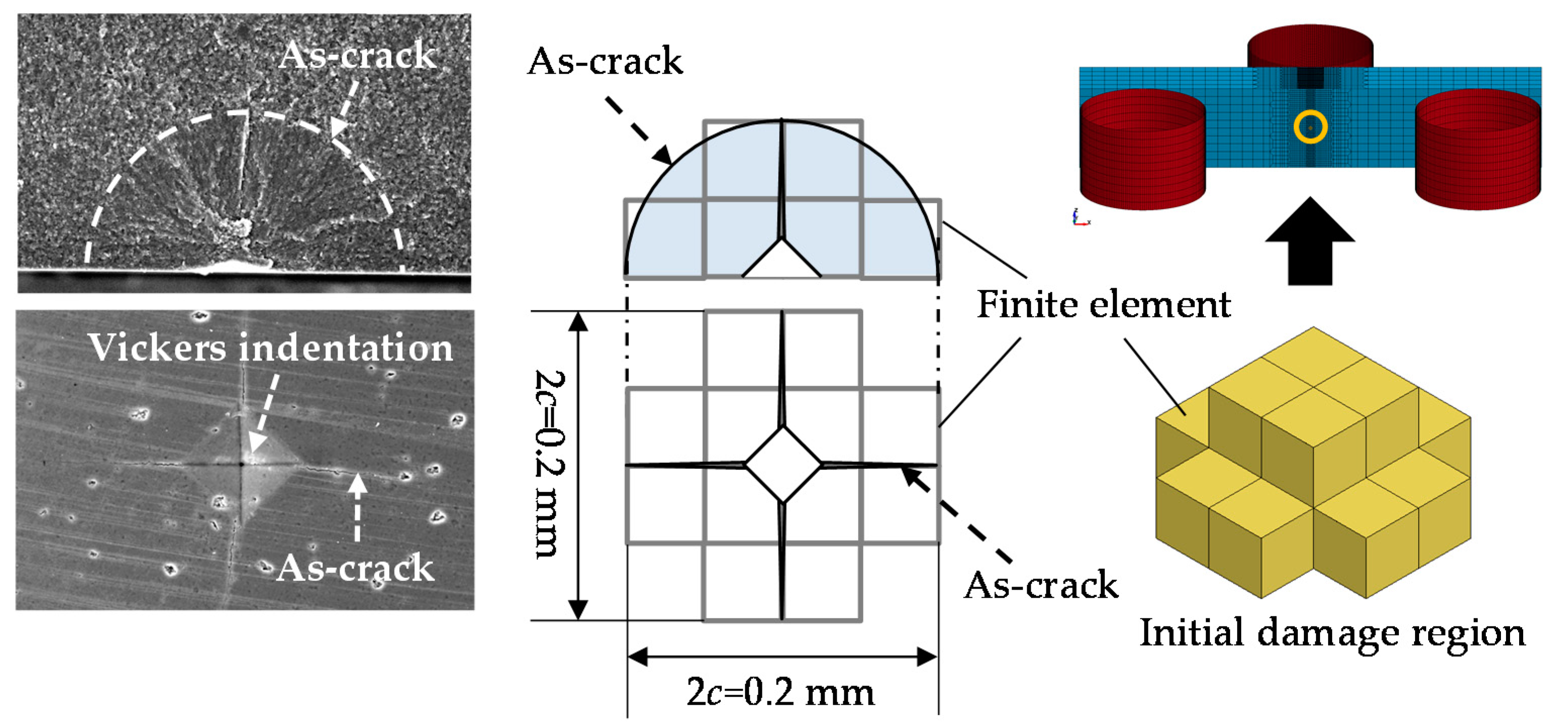
Figure 2 shows the FE model, where the size of the specimen is the same as that of the specimen used in the experiment to be compared with. Because the central part of the bottom surface of the specimen was indented, we modeled that part as an initial damaged region. Here, the parameters used for the FEA are the same as those shown in Table 1 and Table 2.
Since a quadrangular indenter was used in the experiment, a cruciform crack was introduced, as shown in Figure 3. In this study, however, the damaged region was set in a pyramidal shape, equivalent in size to the damaged region formed in the experiment. The figure also shows the shape of the initial damage region. The degree of damage was homogenized in the initial damage region and was set as (D = 0.826) with reference to the crack opening width of the experiment.
3.2. Comparison with the Experimental Result of the Self-Healing Behavior
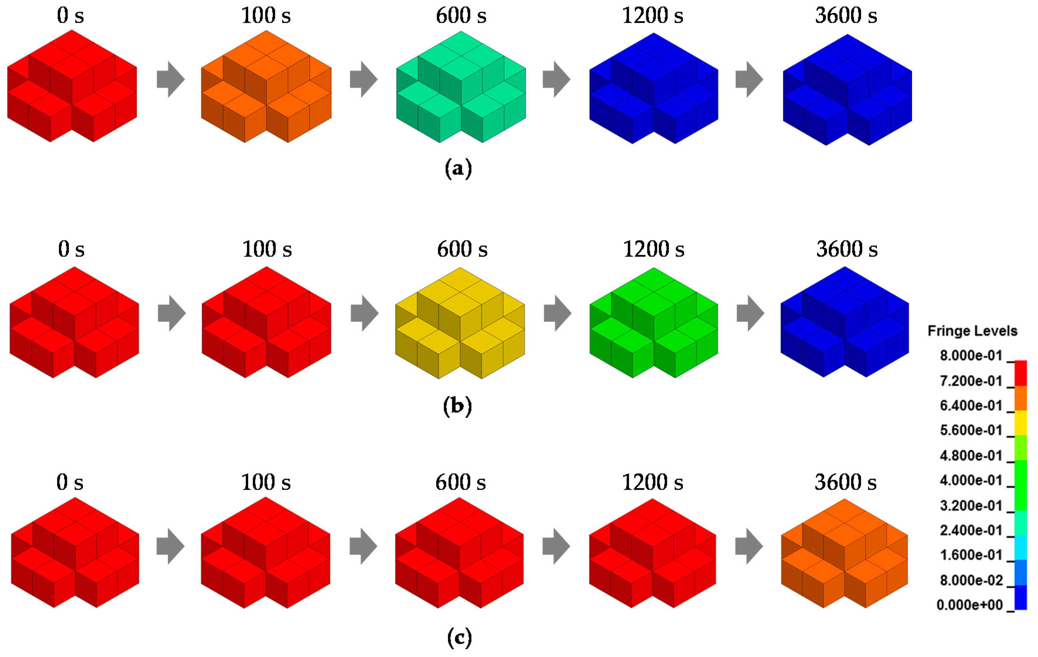
To verify the self-healing process, we investigated the distribution variations for the damage variable D in the initial damage region. Figure 4 shows the contour map for the damage variable D during self-healing in three kinds of environments. Large damages are represented in red, while small damages are indicated in blue. As can be seen from the figure, due to the introduction of the evolution rule based on oxidation kinetics, the damaged region recovers its robust state over longer healing times. In addition, the recovery speed is faster as the temperature and oxygen partial pressures are higher. When the oxygen partial pressure is quite low, the damaged region hardly recovers, even after long-term healing.
Next, we discuss the result of the three-point bending analysis. In the self-healing process shown in Figure 4a, three-point bending analysis was carried out as shown in the model of Figure 2 after the prescribed healing time. Figure 5 shows the bending stress–strain curves obtained by FEA. Figure 5a shows the result of a non-damaged specimen (which corresponds to the non-damaged polished specimen heat-treated at 1573 K for 3600 s used in the experiment) and an as-cracked specimen. Figure 5b shows the bending stress–strain curves at the healing temperature of 1623 K and an oxygen partial pressure of 0.05. As shown in the contour map in Figure 5c, the damage (red part) initiates from the lower surface of the specimen and propagates to the upper surface. The loading stages (i)–(iii) correspond to those in Figure 5b. As is evident from the figure, the three-point bending strength recovers as healing time increases. Owing to the small initial damage region and the bending stress distribution characteristics of the three-point bending test, the stiffness remained unaffected after self-healing. This can be also confirmed by the results shown in Figure 5a. In addition, the fracture initiation site and subsequent crack propagation path also remained unaffected after self-healing. This is because the distribution of the internal defects in each part of the specimen (Figure 3) that cause variation in strength were not considered in the present FEA. Usually, a self-healed part recovers to a robust state. Therefore, based on the weakest link theory, the crack initiation point after complete healing may deviate from the initial damage region and thus the subsequent damage propagation path will be different [7,8]. As a result, the bending strength after complete healing may increase compared to that of the non-damaged specimen. This phenomenon—called super-healing—can be explained by considering the distribution of the material strength in the specimen.
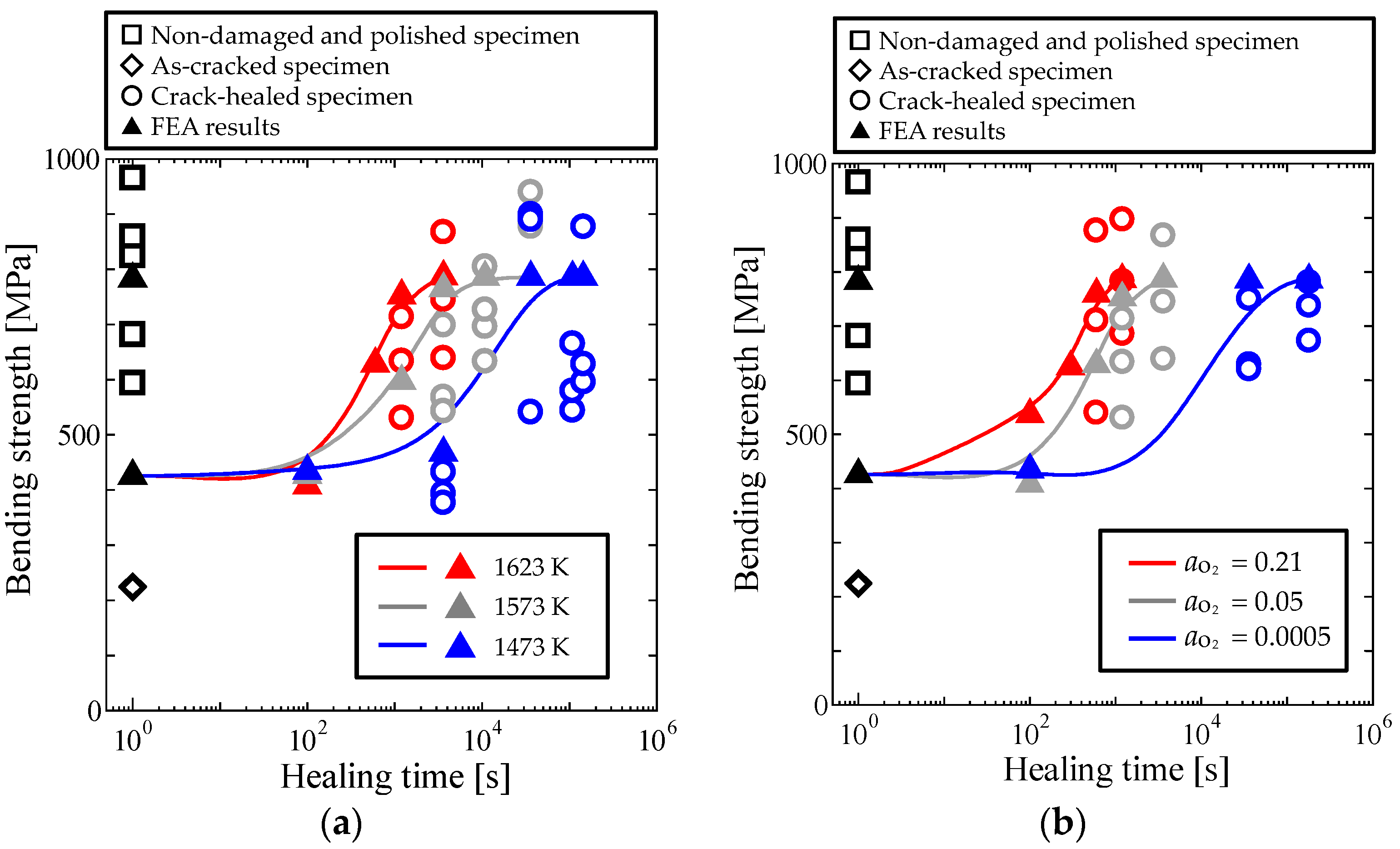
Figure 6 shows a comparison between the strength recovery dependence on the self-healing conditions of the FEA and the experiment. The open symbols represent the experimental results, whereas the closed triangles represent the FEA results, and are shown together with the approximate curves. The plots include the results for the as-cracked and non-damaged specimens.
Figure 6a shows the experimental and FEA results of strength recovery via crack healing as a function of the healing time at different temperatures and an O2 activity of . In the experiment, the crack width—which corresponds to the crack opening displacement—is affected by creep at different self-healing temperatures. The results of the healing temperature dependence of the strength recovery obtained by FEA were in good agreement with those obtained experimentally.
Figure 6b shows the experimental and FEA results of strength recovery via crack healing as a function of the healing time under various O2 partial pressures at a healing temperature of 1623 K. It was confirmed from the results that the variation in strength recovery with healing time—which depends on the O2 partial pressure—can be simulated by the proposed FEA scheme using the damage-healing constitutive model.
However, in both graphs, the bending strength after complete recovery obtained by FEA seemed to be smaller or larger than that obtained in the experiment. The reason is that the variation in strength peculiar to ceramics was not considered in the present FEA. The Weibull modulus of the alumina/15 vol% SiC composite used for comparison is 8.95, and the scale parameter is 891 MPa. Furthermore, the three-point bending strength for a 99% failure probability is 1105 MPa, while that for a 5% failure probability is 639 MPa. In the present FEA, the bending strength was set according to the average strength of five non-damaged specimens in the graphs. Therefore, it is thought that the strength recovery after self-healing can be predicted within a certain error limit range of strength by setting the fracture parameters according to the Weibull distribution of the target materials.
4. Conclusions
In this study, we applied the previously proposed constitutive model to the FEA of a series of healing and damage processes. The boundary condition and procedure corresponded to those of an experiment in which the temperature and O2 activity dependence of the self-healing behavior was investigated. Thereafter, the self-healing behavior obtained by FEA was quantitatively compared with that obtained by the experiment. Interestingly, the ranges of the oxygen partial pressure and healing temperature used in this study were set by considering the conditions that various turbine components are subjected to. We concluded that the present FE approach could be used to study the mechanical and material design of self-healing ceramic materials under the conditions experienced by jet engines.
However, we focused on the fracture process caused by tensile cracking due to three-point bending. The effectiveness of the present FEA for mode II cracking, mode III cracking, and compressive fractures needs to be examined in the near future.
Acknowledgments
This work has been supported by the Grant-in-Aid for challenging Exploratory Research 16K14111 and the Advanced Low Carbon Technology Research and Development Program (ALCA), JST, Japan. We would like to thank Editage (www.editage.jp) for English language editing.
Author Contributions
Marika Nakamura and Kyohei Takeo performed the FEA; Toshio Osada conceived and designed the experiments and provided their detailed data; Shingo Ozaki wrote the paper.
Conflicts of Interest
The authors declare no conflicts of interest.
References
- Halbig, M.C.; Jaskowiak, M.; Kiser, J.D.; Zhu, D. Evaluation of ceramic matrix composite technology for aircraft turbine engine applications. In Proceedings of the 51st AIAA Aerospace Sciences Meeting Including the New Horizons Forum and Aerospace Exposition, Grapevine, TX, USA, 7–10 January 2013; pp. 1–11. [Google Scholar]
- Nakao, W.; Maruoka, D.; Ozaki, S.; Nanko, M.; Osada, T. Advanced ceramic composite using self-healing fiber-reinforcement. In Mechanical Properties and Performance of Engineering Ceramics and Composites IX, Ceramic Engineering and Science Proceedings; John Wiley & Sons, Inc.: Hoboken, NJ, USA, 2014; pp. 187–193. [Google Scholar]
- Ando, K.; Chu, M.C.; Tsuji, K.; Hirasawa, T.; Kobayashi, Y.; Sato, S. Crack healing behaviour and high-temperature strength of mullite/SiC composite ceramics. J. Eur. Ceram. Soc. 2002, 22, 1313–1319. [Google Scholar] [CrossRef]
- Ando, K.; Furusawa, K.; Takahashi, K.; Sato, S. Crack-healing ability of structural ceramics and a new methodology to guarantee the structural integrity using the ability and proof-test. J. Eur. Ceram. Soc. 2005, 25, 549–558. [Google Scholar] [CrossRef]
- Nakao, W.; Mori, S.; Nakamura, J.; Takahashi, K.; Ando, K.; Yokouchi, M. Self-crack-healing behavior of mullite/SiC particle/SiC whisker multi-composites and potential use for ceramic springs. J. Am. Ceram. Soc. 2006, 89, 1352–1357. [Google Scholar] [CrossRef]
- Osada, T.; Nakao, W.; Takahashi, K.; Ando, K.; Saito, S. Strength recovery behavior of machined Al2O3/SiC nano-composite ceramics by crack-healing. J. Eur. Ceram. Soc. 2007, 27, 3261–3267. [Google Scholar] [CrossRef]
- Osada, T.; Nakao, W.; Takahashi, K.; Ando, K. Kinetics of self-crack-healing of alumina/silicon carbide composite including oxygen partial pressure effect. J. Am. Ceram. Soc. 2009, 92, 864–869. [Google Scholar] [CrossRef]
- Ozaki, S.; Osada, T.; Nakao, W. Finite element analysis of the damage and healing behavior of self-healing ceramics material. Int. J. Solids Struct. 2016, 100, 307–318. [Google Scholar] [CrossRef]
- Kurumatani, M.; Terada, K.; Kato, J.; Kyoya, T.; Kashiyama, K. An isotropic damage model based on fracture mechanics for concrete. Eng. Fract. Mech. 2016, 155, 49–66. [Google Scholar] [CrossRef]
- De Vree, J.H.P.; Brekelmans, W.A.M.; van Gils, M.A.J. Comparison of nonlocal approaches in continuum damage mechanics. Comput. Struct. 1995, 55, 581–588. [Google Scholar] [CrossRef]
- Osada, T. Kinetic model for self-crack-healing in ceramics and possibility of turbine blade applications. In Proceedings of the 4th International Conference on Self-Healing Materials, Ghent, Belgium, 16–20 June 2013; pp. 573–577. [Google Scholar]
- Osada, T.; Nakao, W.; Takahashi, K.; Ando, K. Self crack-healing behavior in ceramic-matrix composites. In Advances in Ceramics Matrix Composites; Woodhead Publishing: Sawston, UK, 2014; pp. 410–441. [Google Scholar]
- LSCT. LS-DYNA User’s Manual; LSCT: Singapore, 2016. [Google Scholar]
Figure 1.
Effect of the self-healing environment on the response of the damage-healing constitutive model during cyclic loading: (a) effect of healing temperature; (b) effect of oxygen partial pressure.
Figure 1.
Effect of the self-healing environment on the response of the damage-healing constitutive model during cyclic loading: (a) effect of healing temperature; (b) effect of oxygen partial pressure.
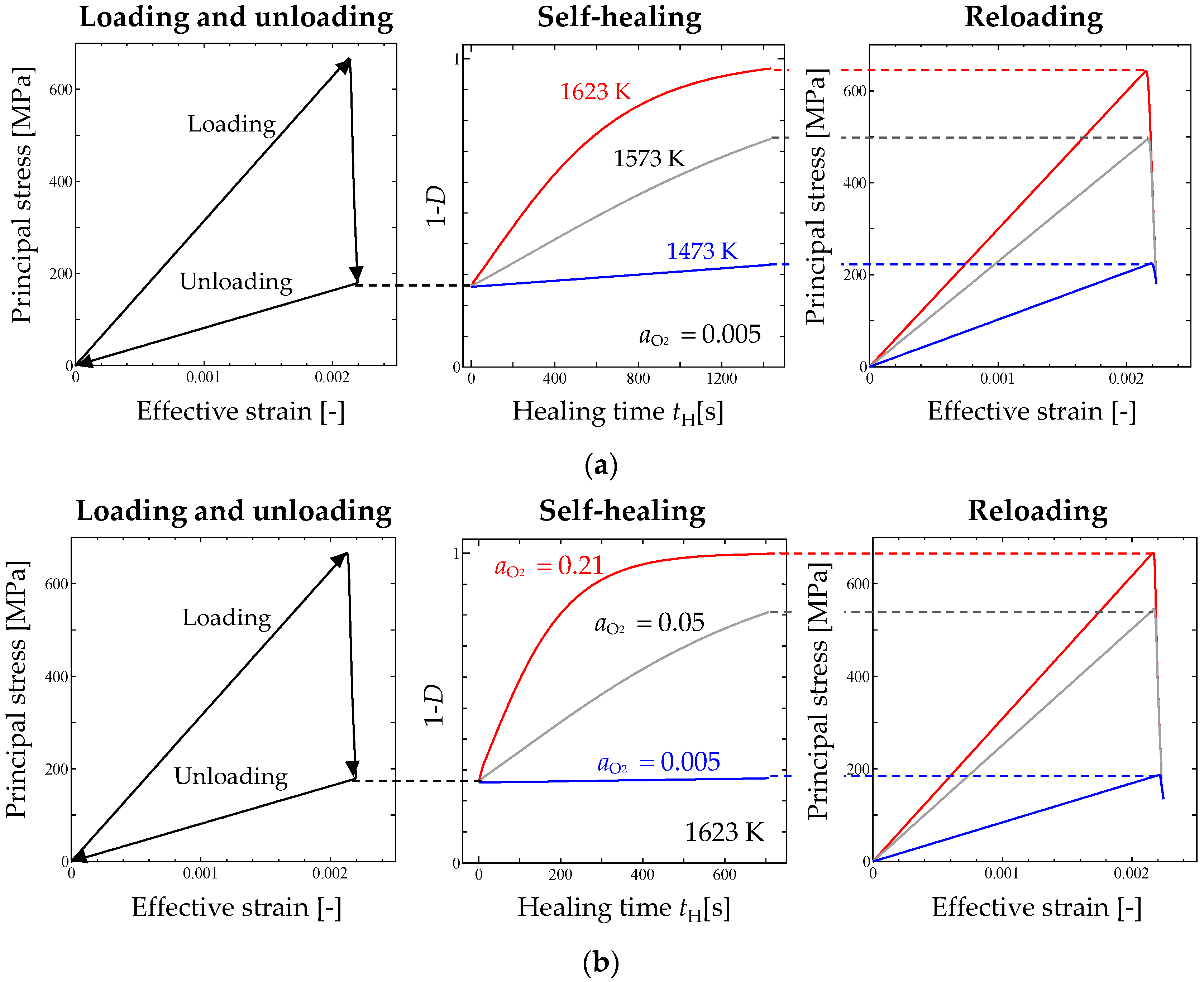
Figure 2.
Finite element (FE) model for simulating the self-healing behavior: (a) dimension of specimen and three-point bending system; (b) initial damage region on the bottom surface.
Figure 2.
Finite element (FE) model for simulating the self-healing behavior: (a) dimension of specimen and three-point bending system; (b) initial damage region on the bottom surface.
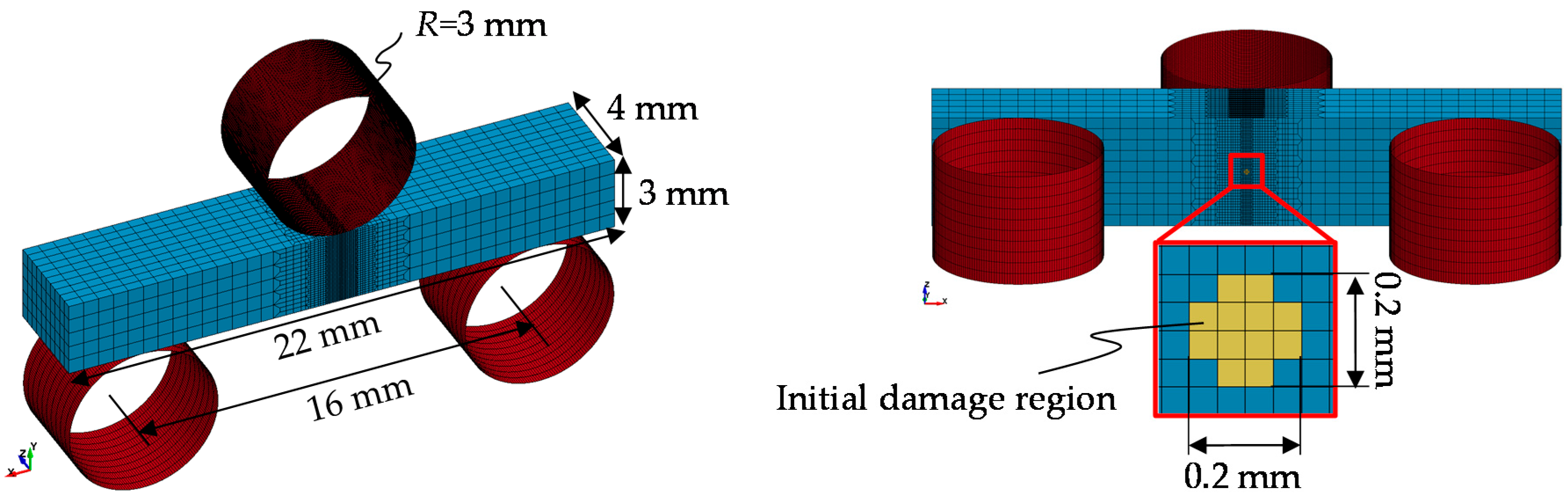
Figure 3.
Finite element modeling of the initial damage region.

Figure 4.
Time series snapshots for the self-healing process during finite element analysis (FEA): (a) ; (b) ; and (c) .
Figure 4.
Time series snapshots for the self-healing process during finite element analysis (FEA): (a) ; (b) ; and (c) .

Figure 5.
Relationship between the bending stress and strain: (a) result before healing; (b) result after healing; (c) distribution of damage variable. The contour map shows the result of damage propagation in a specimen under a three-point bending test.
Figure 5.
Relationship between the bending stress and strain: (a) result before healing; (b) result after healing; (c) distribution of damage variable. The contour map shows the result of damage propagation in a specimen under a three-point bending test.
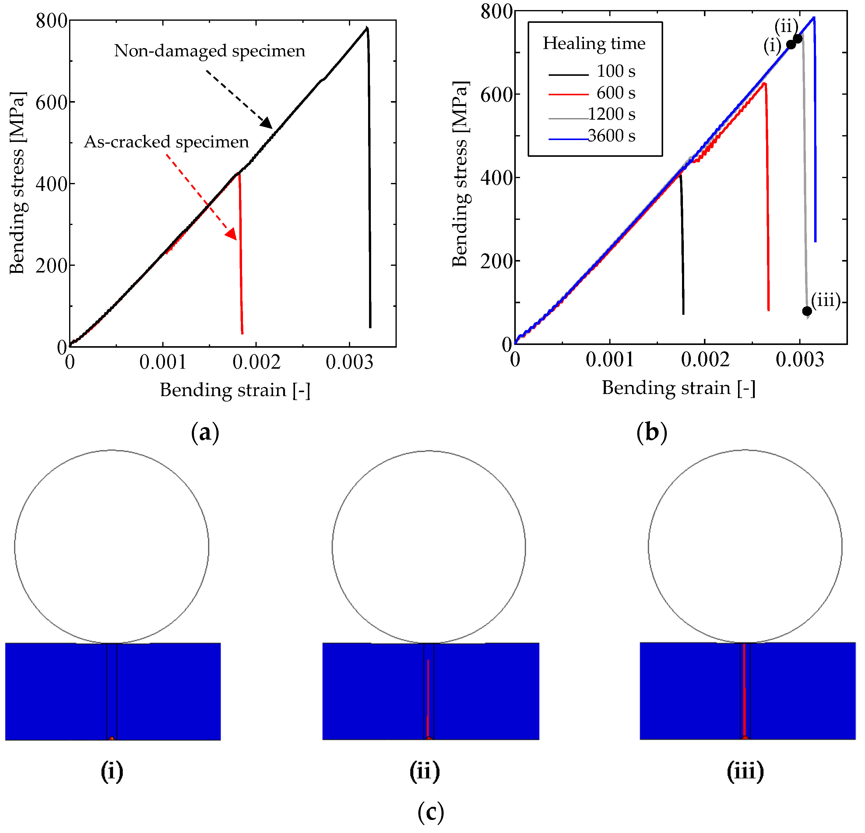
Figure 6.
Strength recovery as a function of healing time in various environments: (a) temperature dependence; (b) O2 partial pressure dependence.
Figure 6.
Strength recovery as a function of healing time in various environments: (a) temperature dependence; (b) O2 partial pressure dependence.

Table 1.
Mechanical parameters of the Al2O3/15 vol% SiC specimen.
| E (MPa) | ν | Gf (MPa/mm) | k | |
|---|---|---|---|---|
| 3.54 × 10⁵ | 0.21 | 3.31 × 10⁻² | 2.14 × 10⁻³ | 10 |
© 2017 by the authors. Licensee MDPI, Basel, Switzerland. This article is an open access article distributed under the terms and conditions of the Creative Commons Attribution (CC BY) license (http://creativecommons.org/licenses/by/4.0/).
Share and Cite
MDPI and ACS Style
Nakamura, M.; Takeo, K.; Osada, T.; Ozaki, S. Finite Element Analysis of Self-Healing and Damage Processes in Alumina/SiC Composite Ceramics. Technologies 2017, 5, 40. https://doi.org/10.3390/technologies5030040
AMA Style
Nakamura M, Takeo K, Osada T, Ozaki S. Finite Element Analysis of Self-Healing and Damage Processes in Alumina/SiC Composite Ceramics. Technologies. 2017; 5(3):40. https://doi.org/10.3390/technologies5030040
Chicago/Turabian StyleNakamura, Marika, Kyohei Takeo, Toshio Osada, and Shingo Ozaki. 2017. "Finite Element Analysis of Self-Healing and Damage Processes in Alumina/SiC Composite Ceramics" Technologies 5, no. 3: 40. https://doi.org/10.3390/technologies5030040
Note that from the first issue of 2016, this journal uses article numbers instead of page numbers. See further details here.