A Low-Cost, Wearable Opto-Inertial 6-DOF Hand Pose Tracking System for VR


Robotics Lab, Department of Mathematics and Computer Science, Liverpool Hope University, Liverpool L16 9JD, UK
*
Author to whom correspondence should be addressed.
Technologies 2017, 5(3), 49; https://doi.org/10.3390/technologies5030049
Submission received: 31 May 2017
/
Revised: 22 July 2017
/
Accepted: 25 July 2017
/
Published: 28 July 2017
(This article belongs to the Special Issue Wearable Technologies)
Abstract
:In this paper, a low cost, wearable six Degree of Freedom (6-DOF) hand pose tracking system is proposed for Virtual Reality applications. It is designed for use with an integrated hand exoskeleton system for kinesthetic haptic feedback. The tracking system consists of an Infrared (IR) based optical tracker with low cost mono-camera and inertial and magnetic measurement unit. Image processing is done on LabVIEW software to extract the 3-DOF position from two IR targets and Magdwick filter has been implemented on Mbed LPC1768 board to obtain orientation data. Six DOF hand tracking outputs filtered and synchronized on LabVIEW software are then sent to the Unity Virtual environment via User Datagram Protocol (UDP) stream. Experimental results show that this low cost and compact system has a comparable performance of minimal Jitter with position and orientation Root Mean Square Error (RMSE) of less than 0.2 mm and 0.15 degrees, respectively. Total Latency of the system is also less than 40 ms.
1. Introduction
Physical immersion and highly interactive systems are important for effective virtual reality applications. User interactions in Virtual Reality (VR) can be displayed in the form of visual, aural and haptic sensory modalities [1,2,3]. Continuous hand tracking is crucial for a more realistic and immersive virtual experiences. Commercial VR devices such as Oculus Rift headset and HTC VIVETM with the integration of hand tracking systems like Leap Motion Controller enables us to experience “visually realistic” interaction with Virtual objects. However, most of these commercial devices does not provide touch feedback (haptics). The integration of haptics in VR devices will improve interactivity and immersion [4]. Fully optical devices like Leap Motion have limited applicability for VR haptic devices. The main reason being the haptic setup on the hand can occlude part of the skin which affects the performance of the tracker. This motivates the development of a low cost hand tracking system for an integration with a lightweight, low cost, wearable and wireless exoskeleton setup for force feedback.
A variety of hand tracking methods have been developed for different application areas including VR. These mechanisms are mainly based on optical, inertial, mechanical, electromagnetic and acoustic sensors [5]. The main consideration in the choice of tracking systems are accuracy and precision, update rate of tracking outputs, robustness to interference and occlusions and encumbrance from wires and mechanical linkages. The presence of a hand exoskeleton in a haptic setup would make use of the mechanical tracking system an easy approach. Mechanical tracking problems involve estimating the motion of one link relative to the attached moving link [6]. Hence, hand tracking problems can be solved by estimating the position of each bone relative to the previous bone. In this case, the entire hand can be arranged as a sequence of attached rigid bodies. The position of the bodies relative to each other can also be solved using multibody kinematics which also enables us to determine the velocity and acceleration of attached bodies. The known kinematic constraints of the hand model improve the accuracy of tracking [7]. This kind of model based hand tracking can be more effective for applications which need hand exoskeletons for Haptics and Rehabilitation [8]. Although the position and orientation of each bone on the hand can be estimated accurately with the hand exoskeleton, tracking of reference frame on the palm or wrist is necessary. Palm position and orientation is used to estimate the pose of the overall hand based on a predefined kinematic hand model.
In this paper, a low cost six Degree of Freedom (6-DOF) tracking of the single point reference frame on palm is discussed using opto-inertial approach. This system aims at providing a relative pose estimation of human hand while immersed in VR environment and wearing an integrated exoskeleton for full hand configuration estimation. Therefore, the current design of the proposed tracking system is part of a mechanical exoskeleton tracking and force feedback system. The system offers a good compromise in terms of cost and efficiency for VR applications with a predefined workspace range and also haptic setups which need hand tracking as an input. In the proposed tracking system, the position and orientation estimation are handled separately. Position is estimated from optical tracking outputs while orientation is estimated from the Inertial Measurement Unit (IMU) tracking outputs. Since we adopt a geometrical approach to estimate the depth tracking, orientation data has been used to correct estimation error. In addition, yaw angle estimation involves the use of optical Infrared (IR) position outputs as a complementary system to reduce IMU heading error from magnetic interference on yaw calculation.
Various optical systems have been designed, typically using video cameras and several Infrared Light Emitting Diodes (LEDs) [9]. Optical systems do not require mapping and provide relatively high accuracies over a large workspace. However, a constant line of sight between the IR LEDs and the camera must be maintained [10]. The performance of this optical system can be affected by occlusion and limiting the coverage area. To overcome the limitations in camera view range, pan-tilt-zoom cameras can be used with visual servoing techniques which follows the markers to be tracked [11]. It is also difficult to insure a proper tracking under different lighting conditions. Inertial sensors, on the other hand, have no range limitation and no line of sight is required. They can give high bandwidth motion measurement with negligible latency. However, they are prone to an interference from magnetic fields [5]. Due to these complementary pros and cons of the two tracking systems, combination of optical and inertial technologies results in more accurate 6-DOF pose tracking [12,13].
Optical Tracking systems detect and track artificial features such as normal LEDs and IR LEDS (active features) or retroactive materials illuminated by Infrared light and a special tag placed onto the hand (passive features). Using passive features could be a problem in the absence of sufficient light; therefore, using active features which emits light is more reliable [13]. To reduce the problems of optical motion tracking related to lightning, Infrared LEDs can be used to completely isolate the markers from the background light. However, this comes at the expense of requiring a special IR camera. Most low cost IR tracking systems use normal Webcams with some modification to pass IR light. Normal Webcams have an infrared blocking filter which prevent the IR from entering. This can be addressed by removing the filter, so that the camera can be sensitive to infrared light. IR detection is more reliable in all lighting conditions; however, for a more accurate tracking a infrared pass-filter can also be added blocking most of the visible light spectrum.
Even though accuracy and precision have lesser importance for VR environments unlike tracking for localization [14], resolution of less than 1 mm and angular precision of greater than 0.2 degrees is important for VR applications. Tracking latency beyond 40–60 ms will also affect the performance of the VR [15].
2. Materials and Methods
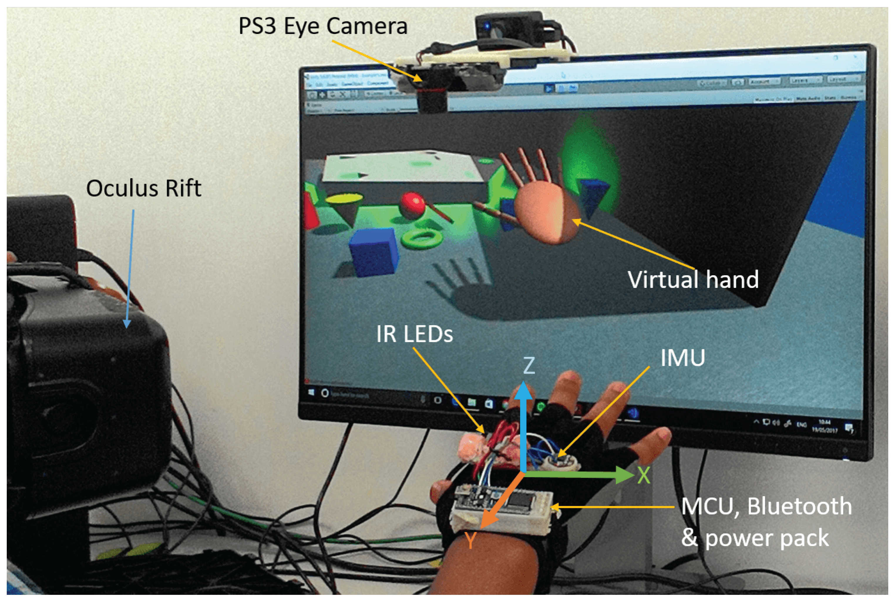
The optical tracking part consists of PlayStation 3 (PS3) eye camera (costs £8) and two IR LEDs while the inertial tracker consists of an LSM9DS0 IMU module which contains a 3-axis gyroscope, 3-axis accelerometer and 3-axis magnetometer in a single chip. The IMU provides a 9-DOFs data stream to the Mbed LPC1768 Microcontroller (32-bit ARM Cortex-M3 running at 96 MHz). A LabVIEW software captures orientation data via Bluetooth at rate of 60 Hz. LabVIEW timed loop enables to trigger reading of both optical and IMU outputs with similar timing sources thereby synchronizing the IR tracking position outputs with the orientation outputs and transfer the 6-DOF pose of the palm through User Datagram Protocol (UDP) connection stream to virtual environment made in Unity 3D.
2.1. Optical Tracking System
Optical Tracking System relies in estimating the pose of the hand from 3D features or targets attached on the hand. In this experiment, two IR LEDs are used as targets. The IR tracking system uses a blob detection and tracking image processing algorithm for positional tracking in 3-DOF. The camera is placed above the workspace (as shown in Figure 1) and tracks 2 IR LEDs placed on the setup. The position of the camera is selected purposely to eliminate the effect of direct light through doors, windows and other light sources. One or two IR LEDs enables us to track 2-DOF while 3 or more LEDs can track 3-DOF position and 3-DOF orientations. The LED viewing angle is also important. Most LEDs focus the light narrowly; therefore, to distribute the light evenly in all direction a diffuser foam cover is used. Wide angle LED can also be used.
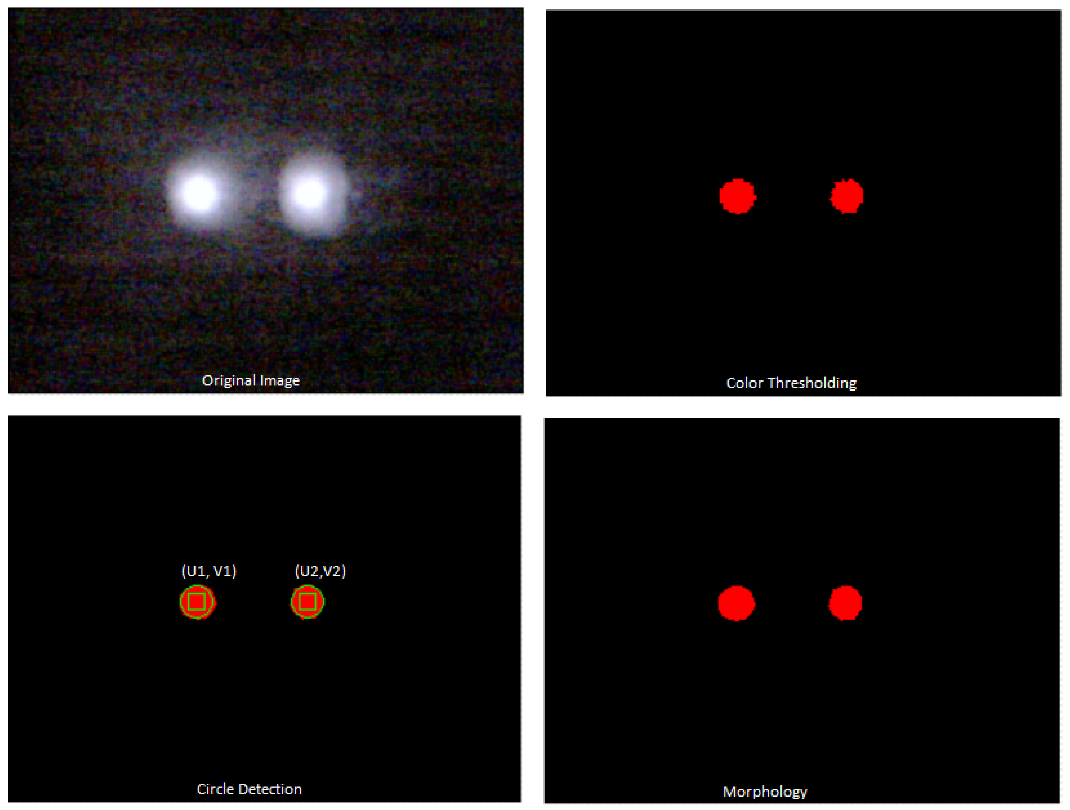
The computer vision algorithms are implemented using LabVIEW National Instrument (NI) vision algorithms. Image frames are acquired continuously with PS3 Eye Camera and NI image acquisition software is used for inline processing. Image acquisition setting are configured as video resolution of 320 × 240 at 60 fps. The infrared LEDs are tracked using a simple image processing algorithm called blob tracking. Blob tracking is more reliable and effective than most complicated image tracking algorithms in a wide range of lighting environment and it can also be done at full frame rate with minimum Central Processing Unit (CPU) usage.The IR LEDs are detected as an area of high brightness in the image. Considering the camera resolution, view range and angle, the workspace of the tracking system is limited to the range of 40 cm width, 30 cm length and 30 cm height. Segmentation is used to distinguish regions (set of pixels), which corresponds to IR markers and the background. RGB ranges are used as a criterion to decide whether a pixel belongs to a region of interest or background. Thresholding applies a threshold of the RGB image in range of Red (0–255), Green (0–255) and Blue (0–202). Pixels outside this range are selected as a region of interest and all other pixels are classified as background.
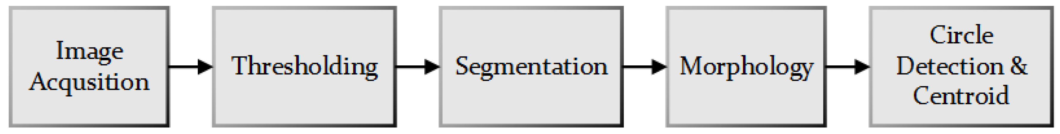
Thresholding results in an 8 bit grayscale image, which has to be inverted to reverse the dynamic of the image. Different morphology techniques are then applied to remove small blobs, and fill holes in the large blobs detected. These morphological operators are selected among other possible operators because they do not affect the estimation of the coordinates of the centroid of the blobs. As shown in Figure 2, the final blobs are characterized by a smooth profile with very much contained glares. A bounding circle is formed around the blobs which helps to extract the measurement results such as number of blobs detected, centre of mass X and centre of mass Y of the blobs. The centre of mass measurements in the X and Y directions given by image coordinates (u, v)are mapped into x and y world coordinates. Figure 3 shows the main blocks of the vision algorithms used to track the IR markers.
A moving body can be tracked using n observed blobs. Each blob corresponds to a point p (x, y, z) with coordinates defined with respect to a reference frame in world coordinate system [16]. The point observed at image coordinate (u, v) provides information about 2-DOFs. If both IR LED are in the field of view of the camera, considering movement on 2D plane only, the x and y position can be estimated from the image coordinates detected as in the following equations.
Where and are scaling factors from image coordinate to real world coordinates. However, For 3-DOF positional tracking, the distance from the camera to the features has to be known. Many algorithms have been developed to determine the depth by solving point model problems with 3 or more IR spots, multiple cameras or stereo cameras can also be used. Using multiple or stereo camera systems increases the complexity and cost of the system where as 3 or more IR targets tracking creates non-stable tracking outputs [17]. In VR applications, considerable spatial accuracy errors are more acceptable than drifts and jitter since users continuously use visual feedback to correct positional errors. On the other hand, drift and jitter creates discomfort for the user. As result, an easier approach has been used to map the depth considering the trade-off between accuracy, cost and computational complexity. This approach is based on mapping the depth with the proportional distance between the 2 IR LEDs.
It is clear that the projection of the distance between the two IR LEDs varies with rotation of the hand with respect to the y axis (roll angle); therefore, the depth calculation can be corrected by adding the roll angle () as factor.
A clear z axis only motion of the IR spots can also produce an error in the x and y axis. This error increases as the position of IR spots is far from the optical axis of the camera. However, the error increases linearly as distance increase from origin; therefore, a calibration matrix (mapping matrix) can be formulated to reduce the error in the x and y axis reading caused by z axis movements. An automatic linear fitting method is used to find the relationship between the depth values and the change in X and Y reading caused by Z axis movement. The following steps have been implemented to find the slope of the deviation in the X and Y axis.
- Find the linear fitting values from the graph of Z vs. X axis and Z vs. Y axis while moving the IR tracker in the Z axis. Slope and intercept is calculated for 10 sample points. To calculate slope and intercepts of data sequence (X, Y)using a least square solution, the LabVIEW linear fit Virtual Instrument (VI) uses the iterative general Least Square method to fit points to a straight line of the formwhere x is the data sequence, m is slope and b is intercept. Every iteration gives linear curve of the formThe least square method finds the slope and intercept which minimizes the residue expressed by the following equation.where N is the length of Y, fi is the ith element of Best Linear Fit, and yi is the ith element of Y.
- Feedback and update the new slope values as coefficient of the calibration matrix ( and )
- Continue to Step 1
Reducing the x and y positional components caused by z axis movements from the pure x and y position reading avoids the error.
This calibrated 3-DOF position can give us smooth and proportional movement mapping between the real hand and virtual hand. Figure 4 shows a test for the above algorithm for a square trajectories on the X-Z plane.
2.2. Inertial Tracking System
The 9-DOF LSM9DS0 MARG (Magnetic, Angular Rate and Gravity) sensor is used to obtain highly accurate orientation tracking with high update rate. The gyroscope measures angular velocity along the three orthogonal axis, accelerometers measure linear acceleration and magnetometer measure magnetic field strength along the three perpendicular axis providing an absolute reference of orientation.
Kalman filters are the most widely used orientation filter algorithms. However, they are complicated for implementation and demand a large computational load which makes it difficult for implementation on small scale microcontrollers. The Magdwick filter has been used as an alternative approach. This filter is effective at low sampling rates, and is more accurate than the Kalman-based algorithm and has low computational load. The MARG system also known as AHRS (Altitude and Heading Reference Systems) is able to provide a measurement of orientation relative to the earth magnetic field and direction of gravity. The algorithm uses a quaternion representation of orientation to reduce singularities associated with Euler angle representations [18].
The magwick filter includes an online gyroscope bias drift compensation. The gyroscope zero bias drift overtime caused by temperature and motion with time. Mahony et al. [19] showed that the gyroscope bias drift can also be compensated by orientation filter through integral feedback in the rate of change of orientation. Magdwick approaches have also implemented a similar algorithm for gyroscope drift compensation [18].
Pitch, roll and yaw angles can be purely estimated from quaternion values. However, estimation of yaw angle involves magnetometer data which can be affected by elevation and tilt angle as well as hard and soft iron bias. Hard iron biases can be removed using different calibration techniques [20]. Soft iron biases cause errors in the measured direction of the Earth’s magnetic field. Declination errors need additional reference heading while inclination errors can be compensated for using the accelerometer as it provides an additional measurement of the sensor’s attitude. The magnetometer used in our application is calibrated to reduce the yaw drift error. However, due to a nearby magnetic object, the sensor reading becomes more dependent on the change in place. Such cases reduce the reliability of the magnetometer to produce an accurate yaw orientation. Therefore, the camera information is used as an additional source of detecting yaw orientation. Since the camera optical axis is parallel to the yaw axis, two IR LEDs position information can be used to estimate the yaw orientation easily.
2.3. Performance Evaluation
Tests has been done to characterize the resolution, static and dynamic spatial accuracy of the overall tracking system. The resolution is the smallest change of position or orientation that the tracking system is able to detect. Resolution is limited either by jitter or quantization levels. The visual effect of the jitter on computer display can affect the user’s haptic experiences. Static accuracy is the amount of reading error when the position and orientation remain constant. Errors due to noise, scale factor error and non-linearity can be shown on static accuracy tests. Very low frequency error components which can be perceived over a period of time are categorized under the term stationary drift. The jitter is the rapidly changing error component [5]. The static accuracy is calculated as the Root Mean Square (RMS) error of the recorded position and orientation angles from the true ones when the tracking sensors are held at a known fixed position and recording the position and orientation output data stream for a 10 min period of time.
For the position static accuracy test, the target LEDs are taped on a sheet of paper with a square grid. The grid origin is aligned with the camera optical axis. A variety of known fixed positions and orientations are tested to see if the static accuracy could vary significantly depending on the position. From the static experimental results, drift and jitter can be seen due to the quantization error.
In order to remove jitter and drifts, smoothing filters of rectangular moving average are used. The moving average filter is an optimal filter to reduce random noises and retain sharp response. It is especially used for time domain signals. The moving average filter operates by averaging a number of points from the input signal to produce each point in the output signal. In our case, all samples in the moving average window are weighted equally to remove spikes in the signal. The moving average can be expressed in the equation form as
Where x [i] is the input signal, y [i] is the output signal, and M is the number of points on average. The result shows that most of the jitter and drift is voided by using the filter. Removing the continuous jitter is particularly important for VR application, even more so than having spatial accuracy. For angular static accuracy testing, we mounted the IMU on Goniometer attached with a stable box. Orientation outputs are recorded for fixed roll, pitch and yaw angles.
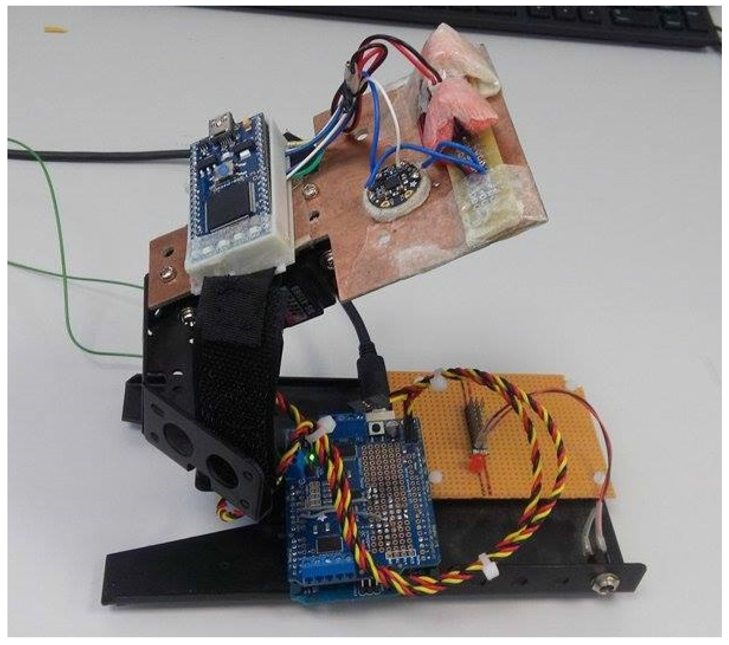
Dynamic positional accuracy tests are done with a calibrated 3D printer head which can be manually driven with a resolution of 10 mm or 20 mm jogging mode in the x and y axis and 10 mm jogging mode in the z axis as a “ground truth” reference system. Dynamic position readings are recorded while moving the 3D printer head in the x, y and z position. Angular dynamic accuracy tests are performed on the two axis gimbals shown in Figure 5. Angular data streams are recorded while rotating the gimbals with a mounted servo motor.
3. Results
Position Data has been collected by placing the IR targets at fixed 3D positions on square grid for 10 min. The recorded data is used to compute the Root Mean Square Error (RMSE) by subtracting the mean value from each set of position readings according to the following equation.
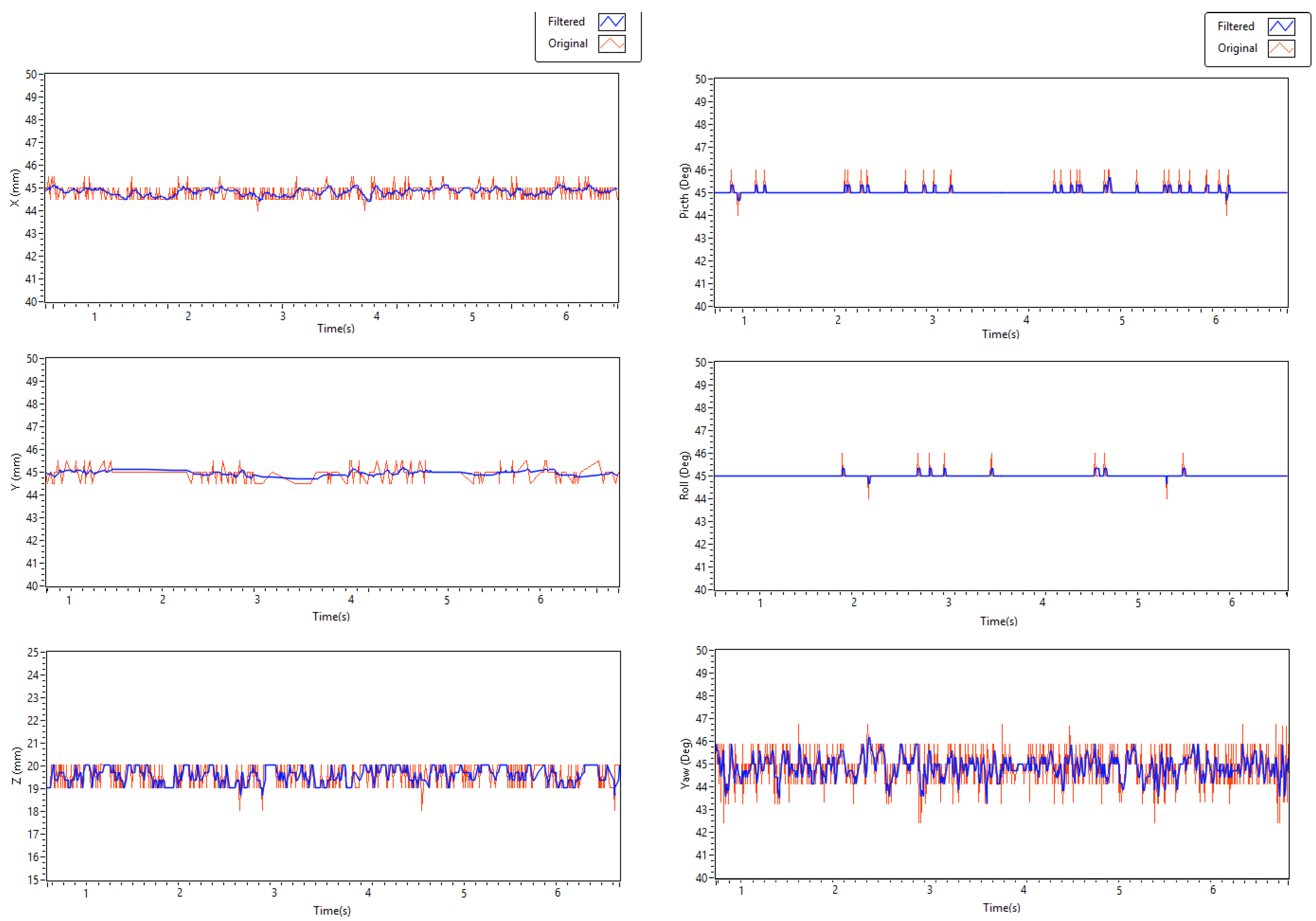
Where are recorded data values and is the mean value of n data points. The resulting RMSE for x, y and z are 0.288 mm, 0.268 mm and 0.653 mm respectively. Most of these errors are caused by quantization levels. This is because the position readings are directly mapped with the position of the blob centres in pixels which are always integer values. A camera with high resolution can give us a more accurate reading. The jitter is reduced by filtering to avoid the rapid flickering of the virtual hand. As shown in Table 1 the position RMSE error is reduced using a rectangular moving average smoothing filter to 0.148 mm, 0.104 mm and 0.373 mm in x, y and z direction respectively.
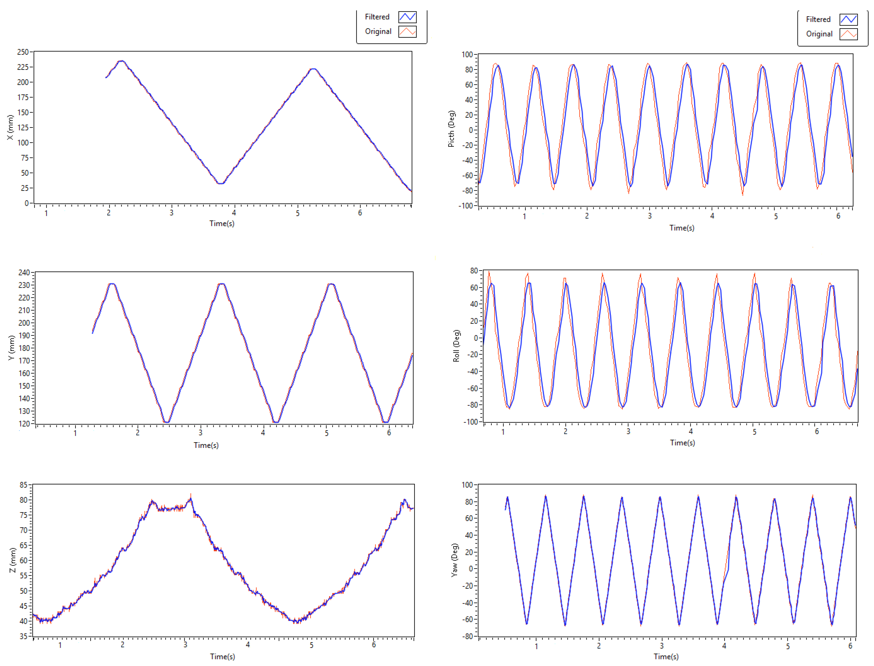
To test the dynamic performance of the IR tracker, data are collected while moving the IR targets mounted on a 3D printer head. The printer head moves for a continuous 10 mm jog mode in one direction and repeats the same movement in the opposite direction where each 10 mm movement has constant velocities.
For static orientation tests, the IMU is fixed at different roll, pitch and yaw angles measured by Goniometer. Test results show that orientation results are accurate except for some drift, which occurred due to sensor bias or noise. To reduce the drift, the same smoothing filter has been used and RMSE error are reduced to 0.113, 0.709 and 0.486 pitch, roll and yaw angle, respectively. Static position and orientation rest results are shown in Figure 6.
To validate dynamic orientation accuracy, data has been collected while moving the IMU placed on top of the gimbal setup shown in Figure 5. The servos move the gimbals clockwise and counter clockwise repeatedly with constant speed. The speed is reduced to match the update rate of the IMU. Results (as shown in Figure 7) indicate that dynamic orientation is worse at higher speed movement, which may not occur on virtual interactions. Some of the error can also be caused by the jitter of the servos while moving. On the other hand, yaw orientation dynamic tests are free from such errors since optical tracking is mainly used to get the yaw angle except during occlusion of the IR targets.
4. Conclusions
This paper presents a low cost and wearable approach for integration of hand tracking systems in a VR environment. Even though more accurate systems exist on the market and also as research equipment, none of them are affordable and they cannot be easily integrated in a VR environment with haptic setups. Accurate tracking systems which are based on fully optical technologies also have limitations in the presence of haptic devices due to occlusion. These limitations motivate us for the development of tracking systems which can be wearable and easily integrated with VR and haptics applications. Experimental Results shows that our approach can estimate the 6-DOF pose of the hand with reasonable accuracy and low latency. Future works will include a full haptic exoskeleton system which tracks full finger joints positions for a more immersive haptic experience.
Acknowledgments
The authors would like to acknowledge Liverpool Hope University for the research funding and covering the cost of this publication.
Author Contributions
A.T.M., E.L.S. and D.R. conceived and designed the experiment; A.T.M. and T.F.A. develop the experimental setup and perform the experiments; A.T.M. and E.L.S. analyzed the data; D.R. and A.K.N. contributed analysis tools; A.T.M. wrote the paper.
Conflicts of Interest
The authors declare no conflict of interest.
References
- Maereg, A.T.; Secco, E.L.; Agidew, T.F.; Diaz-Nieto, R.; Nagar, A. Wearable haptics for VR stiffness discrimination. In Proceedings of the European Robotics Forum, Edinburgh, UK, 22–24 March 2017. [Google Scholar]
- Andualem, T.M.; David, R.; Atulya, N.; Emanuele, L.S. Integrated wireless and wearable haptics system for virtual interaction. In Proceedings of the EuroHaptics, London, UK, 4–7 July 2016. [Google Scholar]
- Li, M.; Konstantinova, J.; Secco, E.L.; Jiang, A.; Liu, H.; Nanayakkara, T.; Seneviratne, L.D.; Dasgupta, P.; Althoefer, K.; Wurdemann, H.A. Using visual cues to enhance haptic feedback for palpation on virtual model of soft tissue. Med. Biol. Eng. Comput. 2015, 53, 1177–1186. [Google Scholar] [CrossRef] [PubMed] [Green Version]
- Margolis, T.; DeFanti, T.A.; Dawe, G.; Prudhomme, A.; Schulze, J.P.; Cutchin, S. Low cost heads-up virtual reality (HUVR) with optical tracking and haptic feedback. In Proceedings of the Society of Photo-optical Instrumentation Engineers (SPIE), San Francisco, CA, USA, 23–27 January 2011. [Google Scholar]
- Foxlin, E.; Altshuler, Y.; Naimark, L.; Harrington, M. Flighttracker: A novel optical/inertial tracker for cockpit enhanced vision. In Proceedings of the 3rd IEEE/ACM International Symposium on Mixed and Augmented Reality, Washington, DC, USA, 2–5 November 2004. [Google Scholar]
- Gu, X.; Zhang, Y.; Sun, W.; Bian, Y.; Zhou, D.; Kristensson, P.O. Dexmo: An Inexpensive and Lightweight Mechanical Exoskeleton for Motion Capture and Force Feedback in VR. In Proceedings of the CHI Conference on Human Factors in Computing Systems, Santa Clara, CA, USA, 7–12 May 2016. [Google Scholar]
- Steven, M.L. Virtual Reality; Cambridge University Press: Cambridge, UK, 2016. [Google Scholar]
- Secco, E.L.; Sottile, R.; Davalli, A.; Calori, L.; Cappello, A.; Chiari, L. VR-Wheel: A rehabilitation platform for motor recovery. In Proceedings of the Virtual Rehabilitation, Venice, Italy, 27–29 September 2007. [Google Scholar]
- Zaoui, M.; Wormell, D.; Altshuler, Y.; Foxlin, E.; McIntyre, J. A 6 DOF opto-inertial tracker for virtual reality experiments in microgravity. Acta Astronaut. 2001, 49, 451–462. [Google Scholar] [CrossRef]
- He, C.; Kazanzides, P.; Sen, H.T.; Kim, S.; Liu, Y. An inertial and optical sensor fusion approach for six degree-of-freedom pose estimation. Sensors 2015, 15, 16448–16465. [Google Scholar] [CrossRef] [PubMed]
- Cortes, G.; Marchand, É.; Ardouinz, J.; Lécuyer, A. Increasing optical tracking workspace of VR applications using controlled cameras. In Proceedings of the IEEE Symposium on 3D User Interfaces (3DUI), Los Angeles, CA, USA, 18–19 March 2017. [Google Scholar]
- Hogue, A.; Jenkin, M.; Allison, R.S. An optical-inertial tracking system for fully-enclosed VR displays. In Proceedings of the First Canadian Conference on Computer and Robot Vision, London, ON, Canada, 17–19 May 2004. [Google Scholar]
- Patel, K.; Stuerzlinger, W. Simulation of a virtual reality tracking system. In Proceedings of the IEEE International Conference on Virtual Environments Human-Computer Interfaces and Measurement Systems (VECIMS), Ottawa, ON, Canada, 19–21 September 2011. [Google Scholar]
- Calloway, T.; Megherbi, D.B. Using 6 DOF vision-inertial tracking to evaluate and improve low cost depth sensor based SLAM. In Proceedings of the IEEE International Conference on Computational Intelligence and Virtual Environments for Measurement Systems and Applications (CIVEMSA), Budapest, Hungary, 27–28 June 2016. [Google Scholar]
- Pintaric, T.; Kaufmann, H. Affordable infrared-optical pose-tracking for virtual and augmented reality. In Proceedings of the IEEE VR Workshop on Trends and Issues in Tracking for Virtual Environments, Charlotte, NC, USA, 11 March 2007. [Google Scholar]
- Marchand, E.; Uchiyama, H.; Spindler, F. Pose estimation for augmented reality: A hands-on survey. IEEE Trans. Vis. Comput. Graph. 2016, 22, 2633–2651. [Google Scholar] [CrossRef] [PubMed]
- Satyavolu, S.; Bruder, G.; Willemsen, P.; Steinicke, F. Analysis of IR-based virtual reality tracking using multiple Kinects. In Proceedings of the IEEE Virtual Reality Short Papers and Posters (VRW), Costa Mesa, CA, USA, 4–8 March 2012. [Google Scholar]
- Madgwick, S.O.; Harrison, A.J.; Vaidyanathan, R. Estimation of IMU and MARG orientation using a gradient descent algorithm. In Proceedings of the IEEE International Conference on Rehabilitation Robotics (ICORR), Zurich, Switzerland, 29 June–1 July 2011. [Google Scholar]
- Mahony, R.; Hamel, T.; Pflimlin, J.M. Nonlinear complementary filters on the special orthogonal group. IEEE Trans. Autom. Contr. 2008, 53, 1203–1218. [Google Scholar] [CrossRef] [Green Version]
- Vasconcelos, J.F.; Elkaim, G.; Silvestre, C.; Oliveira, P.; Cardeira, B. Geometric approach to strapdown magnetometer calibration in sensor frame. IEEE Trans. Aerosp. Electron. Syst. 2011, 47, 1293–1306. [Google Scholar] [CrossRef]
Figure 1.
Virtual reality 6 Degree of Freedom (6-DOF) tracking experimental setup.

Figure 2.
Blob detection and tracking algorithm outputs.

Figure 3.
Blob tracking: Image processing algorithms.

Figure 4.
Square trajectory plot: Calibration tests in X-Z plane, Z-Y plane and Y-X plane.
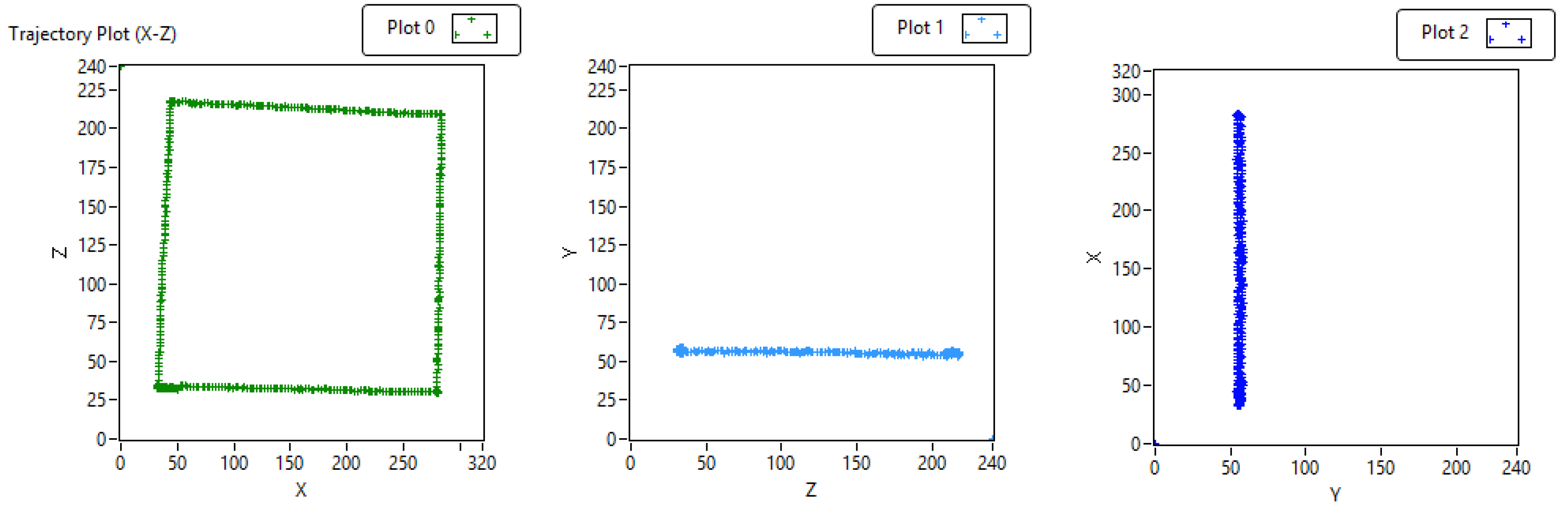
Figure 5.
Orientation dynamic accuracy test setup.

Figure 6.
Static position and orientation accuracy test results.

Figure 7.
Position and orientation dynamic accuracy tests.


Table 1.
Position and orientation Root Mean Square Error (RMSE): Static accuracy test.
| Position RMSE (mm) | Orientation RMSE (Degrees) | ||||
|---|---|---|---|---|---|
| Axis | Original | Filtered | Angle | Original | Filtered |
| X | 0.288 | 0.148 | Pitch | 0.199 | 0.113 |
| Y | 0.268 | 0.104 | Roll | 0.137 | 0.079 |
| Z | 0.653 | 0.373 | Yaw | 0.831 | 0.486 |
© 2017 by the authors. Licensee MDPI, Basel, Switzerland. This article is an open access article distributed under the terms and conditions of the Creative Commons Attribution (CC BY) license (http://creativecommons.org/licenses/by/4.0/).
Share and Cite
MDPI and ACS Style
Maereg, A.T.; Secco, E.L.; Agidew, T.F.; Reid, D.; Nagar, A.K. A Low-Cost, Wearable Opto-Inertial 6-DOF Hand Pose Tracking System for VR. Technologies 2017, 5, 49. https://doi.org/10.3390/technologies5030049
AMA Style
Maereg AT, Secco EL, Agidew TF, Reid D, Nagar AK. A Low-Cost, Wearable Opto-Inertial 6-DOF Hand Pose Tracking System for VR. Technologies. 2017; 5(3):49. https://doi.org/10.3390/technologies5030049
Chicago/Turabian StyleMaereg, Andualem T., Emanuele L. Secco, Tayachew F. Agidew, David Reid, and Atulya K. Nagar. 2017. "A Low-Cost, Wearable Opto-Inertial 6-DOF Hand Pose Tracking System for VR" Technologies 5, no. 3: 49. https://doi.org/10.3390/technologies5030049
Note that from the first issue of 2016, this journal uses article numbers instead of page numbers. See further details here.