Very Low-Cost 80-Bit Chipless-RFID Tags Inkjet Printed on Ordinary Paper
by
 , ,
, ,
Cristian Herrojo
1,* ,
,
Miquel Moras
2,
Ferran Paredes
1 ,
,
Alba Núñez
2,
Eloi Ramon
2,
Javier Mata-Contreras
3 and
Ferran Martín
1 1
CIMITEC, Departament d’Enginyeria Electrònica, Universitat Autònoma de Barcelona, 08193 Bellaterra, Spain
2
Institut de Microelectrònica de Barcelona, IMB-CNM (CSIC), 08193 Bellaterra, Spain
3
Departamento de Ingeniería de Comunicaciones, Universidad de Málaga, 29016 Málaga, Spain
*
Author to whom correspondence should be addressed.
Technologies 2018, 6(2), 52; https://doi.org/10.3390/technologies6020052
Submission received: 12 March 2018
/
Revised: 17 May 2018
/
Accepted: 18 May 2018
/
Published: 22 May 2018
(This article belongs to the Special Issue Chipless RFID Technologies)
Abstract
:This paper presents a time-domain, chipless-RFID system with 80-bit tags inkjet-printed on ordinary DIN A4 paper. The tags, consisting of a linear chain of resonant elements (with as many resonators as the number of identification bits plus header bits), are read sequentially and by proximity (through near-field coupling). To this end, a transmission line, fed by a harmonic (interrogation) signal tuned to the resonance frequency of the tag resonators (or close to it), is used as a reader. Thus, during reader operation, the tag chain is mechanically shifted over the transmission line so that the coupling between the line and the functional resonant elements of the tag chain is favored. Logic states that ‘1’ and ‘0’ are determined by the functionality and non-functionality (resonator detuning), respectively, of the resonant elements of the chain. Through near-field coupling, the transmission coefficient of the line is modulated and, as a result, the output signal is modulated in amplitude (AM), which is the identification code contained in the envelope function. As long as the tags are inkjet-printed on ordinary DIN A4 paper, the cost is minimal. Moreover, such tags can be easily programmed and erased, so that identical tags can be fabricated on a large scale (and programmed at a later stage), further reducing the cost of manufacture. The reported prototype tags, with 80 bits of information plus four header bits, demonstrate the potential of this approach, which is of particular interest to secure paper applications.
1. Introduction
Chipless radiofrequency identification (chipless-RFID) has emerged in the last fifteen years as an alternative to RFID systems with tags equipped with silicon integrated circuits (IC) or chips [1,2,3,4,5,6]. State-of-the-art chipless-RFID systems cannot compete with chipped-RFID in terms of data storage capacity, size, and read distances [7,8]. However, one clear limitation of chipped tags is their cost, which is connected to the necessary presence of the silicon chip. Chipless-RFID tags solve this problem. Thus, chipless-RFID systems are of particular interest to applications devoted to low-cost tagged items.
Recently, numerous efforts have been dedicated to improving the data storage capability of chipless-RFID systems and to reduce the size of the ID encoders, typically consisting of a metallic pattern printed on a flexible dielectric substrate (which include plastic or paper, among others). There are two predominant strategies for the implementation of chipless-RFID systems: (i) time-domain systems [9,10,11,12,13,14], and (ii) frequency-domain systems [1,2,15,16,17,18,19,20,21,22,23,24,25,26,27,28,29,30]. In time-domain systems, the typical operation principle is time-domain reflectometry (TDR). The ID code is contained in the echoes, which are generated by a delay line with scatters (encoder) in response to a pulsed (interrogation) signal. Unless SAW (Suface Acoustic Wave) technology is considered [31,32,33,34,35], TDR-based tags which can be implemented by either etching or printing the encoders on a planar substrate exhibit a very limited data storage capability [10,13]. In frequency-domain systems, 35-bit tags have been reported by loading a transmission line with spiral resonators [1,15]. In such frequency-domain tags, also known as spectral signature barcodes, the ID code is provided by the singularities present in the radar-cross section (RCS) response (backscattered tags) [22] or in the magnitude or phase of the retransmitted response (retransmission-based tags) [15,16,23]. Typically, the number of bits determine the number of resonators needed, with each resonator tuned to a different frequency. Therefore, the spectral bandwidth of such frequency-domain tags increases with the number of bits, and a very wide multi-frequency (sweeping) interrogation signal is required for tag reading, provided such number of bits (or resonators) is significant. This makes the reader more expensive, preventing the implementation of chipless-RFID systems with the number of bits close to that of the standard EPC global (Electronic Product Code) of chipped UHF-RFID (96 bits).
To increase the data density per frequency and per area unit, hybrid tags, which exploit several domains simultaneously, have been reported [36,37,38,39,40,41,42,43,44,45,46,47,48,49]. Examples include tags where frequency position is combined with phase deviation [36], with polarization diversity [37], or with notch bandwidth [48] as well as tags in which the frequency is combined with the peak [41,42] or notch [43,44] magnitude, among others [38,39,40,45,46,47,49]. In all these cases, more than one bit per resonant element is achieved. Nevertheless, the data storage capability of these hybrid tags is also limited.
Recently, the authors have presented a novel time-domain approach for chipless-RFID systems, in which the number of bits can be dramatically increased [50,51,52,53,54,55]. In this paper, we demonstrate the functionality of this system by reading 80-bit tags (plus header bits) inkjet-printed on ordinary DIN A4 paper. This represents a milestone in terms of number of bits and cost. The low cost arises from the fact that a single layer of conductive ink suffices for the fabrication of readable tags, and ordinary paper is extremely cheap. Moreover, entirely identical tags can be manufactured on a massive scale and then programmed at a later stage, further reducing fabrication costs.
2. The Chipless-RFID System: Operating Principle, Reader, and Tag
2.1. Operating Principle
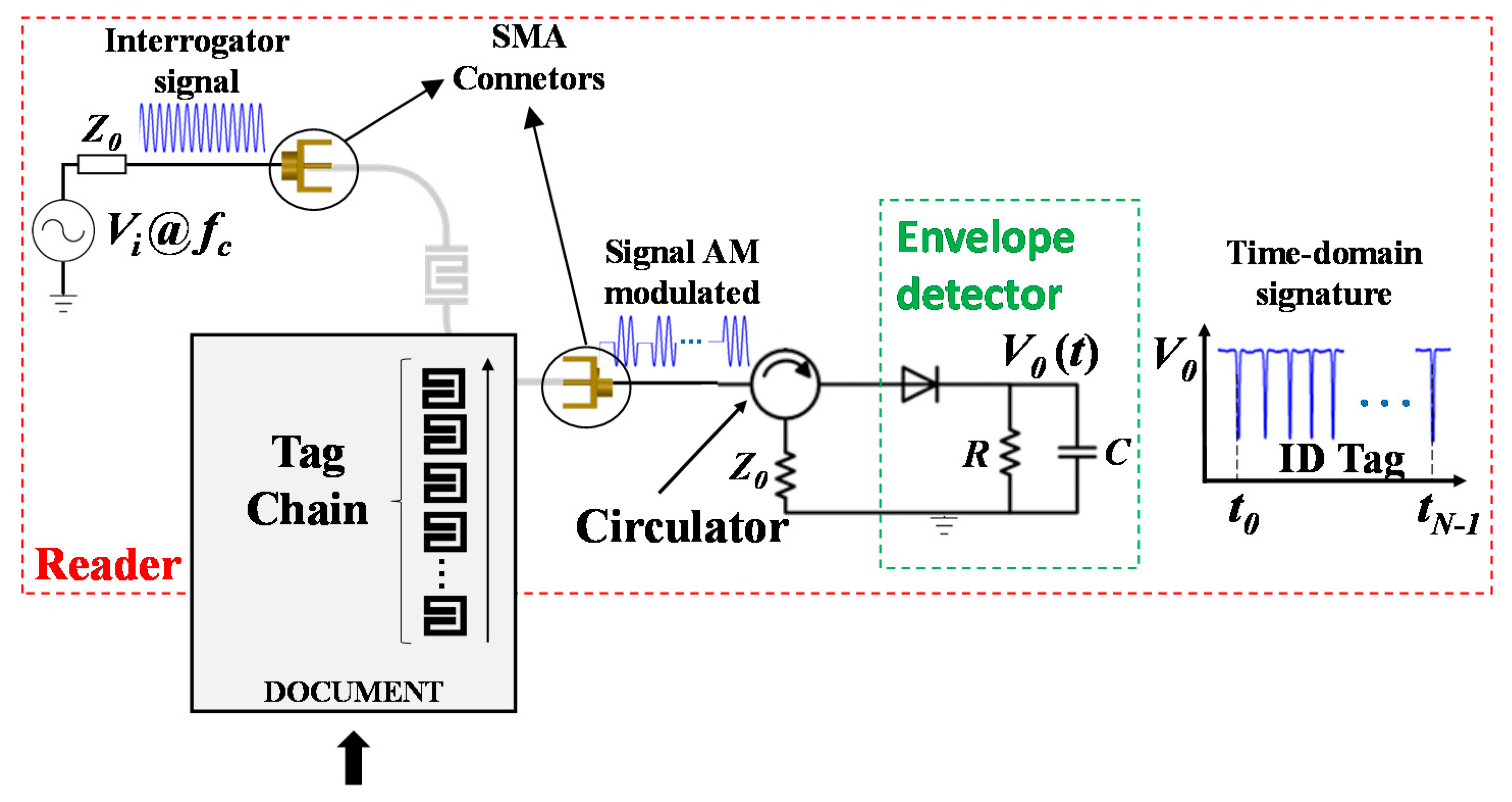
The operating principle of the time-domain chipless-RFID system, which is based on near-field and sequential bit reading was first reported in Herrojo et al. [50] and is succinctly reviewed in this paper for coherence and completeness. The tag consists of a linear chain of resonant elements (all identical) printed or etched at predefined and equidistant positions on a dielectric substrate (typically a flexible substrate, such as plastic, paper, etc.). The ID code is given by the functionality or non-functionality of the resonant elements, in which a resonator is not functional if it is detuned, namely, not resonating at its fundamental resonance frequency. Resonator detuning may be achieved, e.g., by cutting it. For tag reading, an element able to detect the functionality of the resonant elements is required. For such purposes, a transmission line, which is conveniently fed by a single tone signal tuned to the resonance frequency of the tag resonators or close to it, is adequate. Thus, by displacing the tag chain over the fed line, a coupling between the line and the resonant elements is expected (as long as the resonant elements are functional and the distance between the line and the resonant elements is small). Each time a functional resonator lies on top of the line, the coupling prevents the signal from transmitting through the line. The effect is a variation of the transmission coefficient at the feeding frequency due to near-field coupling; consequently, the output signal is amplitude modulated. Hence, the ID code is contained in the envelope function of the amplitude modulated (AM) signal, which can be inferred by means of an envelope detector, a simple circuit able to provide the envelope function where the ID code is contained. Indeed, the ID code is provided in time-domain, where the logic state ‘1’ is given by the dips in the time response of the envelope function. The working principle of this unconventional time-domain chipless-RFID system is illustrated in Figure 1. When compared to frequency-domain chipless-RFID systems, the time-domain approach illustrated in Figure 1 exhibits a significant advantage: the interrogation signal is a harmonic (single tone) signal. Thus, the cost of the reader can be significantly reduced because a multi-frequency sweeping signal is not required. Indeed, the spectral bandwidth of the proposed tags is virtually null because all the resonant elements of the tag are identical (i.e., tuned to the same frequency). The difference between these tags and spectral signature barcodes is that the reading is based on frequency division multiplexing in spectral signature barcodes. In contrast, in the novel chipless-RFID systems proposed by us, time division multiplexing is used for tag reading.
2.2. The Reader
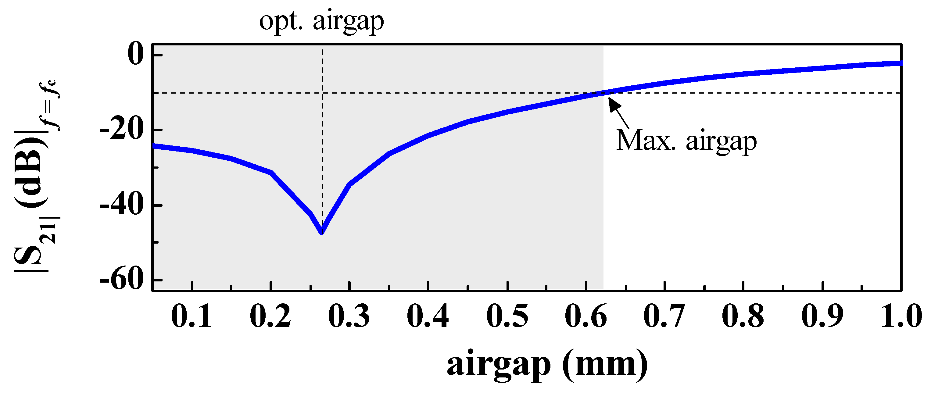
As mentioned in the previous subsection, the active part of the reader is a transmission line fed by a harmonic signal. Particularly, the structure under consideration is a microstrip line loaded with a split-ring resonator (SRR) in bandpass configuration, as depicted in Figure 2 [54]. This structure exhibits two singular frequencies: (i) a reflection zero frequency (where the signal between the input and the output port is transmitted), and (ii) a transmission zero frequency. Accordingly, a large excursion of the transmission coefficient is achieved when a resonant element identical to the SRR of the line is aligned and oppositely oriented to it. The net effect is an overall displacement of the transmission coefficient to the left, as depicted in Figure 2b. By properly tuning the resonator dimensions as well as the vertical distance between the line and the oppositely oriented resonator (air gap), it is possible to optimize the variation of the transmission coefficient at the frequency of maximum transmission of the unloaded SRR-loaded line, fc, as seen in Figure 2b. Thus, the tags will be implemented as chains of SRRs, printed on a different substrate, and tag reading will proceed by mechanically shifting the tag chain over the SRR of the line, with the SRRs of the tag oppositely oriented and aligned with regard to the SRR of the line. In practice, it is difficult to keep the air gap uniform, but some tolerance in the air gap distance is acceptable as long as the variation of the transmission coefficient at fc is significant, even when the air gap deviates from the optimum value (Figure 3).
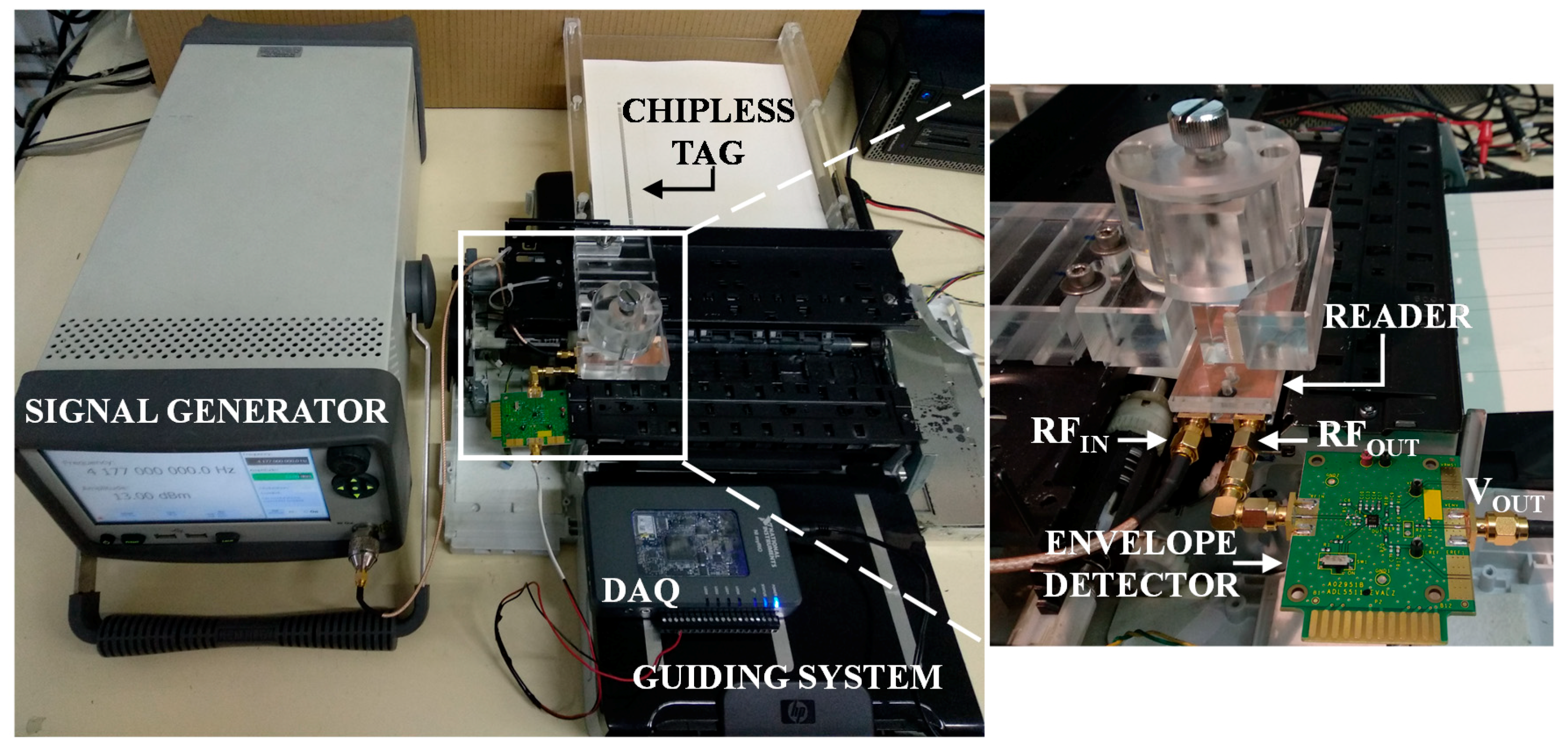
The reader consists not only of the SRR-loaded line but also the envelope detector, plus additional electronics that are necessary to generate the harmonic (interrogation) signal. In numerous studies by Herrojo et al. [50,51,52,53,54,55], the envelope detector was implemented by means of a Schottky diode (Avago HSMS-2860), an active probe which acts as a low-pass filter (with R = 1 MΩ and C = 1 pF) and an isolator to prevent reflections from the diode. In this work, an integrated circuit (Analog Devices ADL5511), able to provide the envelope function (hence reducing cost), was alternatively used. The envelope signal was then driven to a data acquisition card (National Instruments myRIO) connected to a computer, where the sampled data could be viewed. The harmonic feeding signal was generated by means of the Agilent E44338C function generator. An important part of the reader is the mechanical system, which is needed to displace the tag over the transmission line of the reader in close proximity to it. To this end, a printer was adapted and equipped with an adhoc guiding channel to absorb the tag (printed encoder). Good alignment and uniform air gap distance between the tag chain and the resonator of the reader was achieved with this system. Nevertheless, our system supported some tolerances in the vertical direction (air gap) as well as lateral misalignments, as discussed in Herrojo et al. [54]. With regard to the speed of reading, the system is limited by the sampling rate of the reader. However, for any practical mechanical guiding system used to displace the tag over the reader, the achievable speed did not represent an issue in this regard. The photograph of the complete reader is depicted in Figure 4, where the different reader parts are indicated.
2.3. The Tags
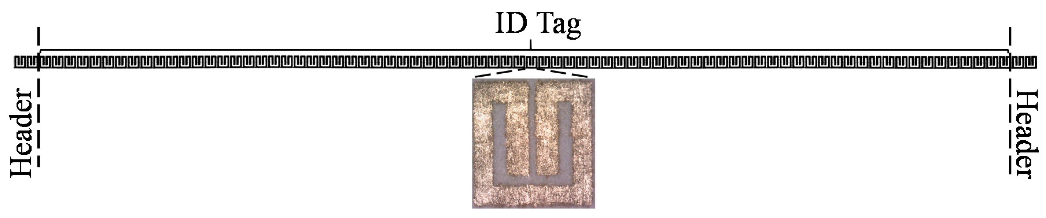
As previously mentioned, the tags consist of a linear chain of SRRs, which is identical to the one of the reader line. To demonstrate the viability of the system with very low-cost tags, we opted to use ordinary DIN A4 paper as tag substrate, with measured dielectric constant and loss tangent of εr = 3.11 and tanδ = 0.036, respectively. Such measurements were carried out by means of the resonant cavity 85072A. Clearly, the response of the SRR-loaded line of the reader, which, in turn, was loaded with the tag, depended on the tag substrate, but this dependence was relatively soft as long as tag substrates with similar thickness and dielectric constant were considered. Note also that the dielectric constant value of the substrate of the reader line was not related to the substrate of the tag. Such value (the dielectric constant of the reader substrate) was chosen relatively high to reduce the size of the resonant element of the reader and, consequently, the resonant elements of the tag (provided they are identical). Moreover, we implemented the tags by inkjet-printing using DupontTM PE410 conductive ink, with a measured conductivity of 7.28 × 10⁶ S/m. One layer (with measured thickness of 2.6 μm) suffices, thereby optimizing tag cost. The number of resonant elements was set to 80 for the ID code (corresponding to 80-bit tags), plus four SRRs for the header bits. Such header bits were needed because the tag could be displaced over the reader starting from the two extremes (corresponding to tag SRRs either face up or down). The photograph of the fabricated tag with all ID bits set to the logic state ‘1’ (i.e., with all resonators functional) is depicted in Figure 5. The total length and width of the tag (including the header bits) was 267.2 mm and 3.35 mm, respectively. With this size, the tag could be accommodated along the longitudinal side of DIN A4 paper. For security and authentication of this type of document, the limit was 88 bits (plus the header bits) because this is the number of bits achievable along the longer side of DIN A4, taking into account that the tag period was 3.36 mm.
Notably, tags can be programmed and erased after fabrication. This is an important aspect which can lead to a further reduction in fabrication costs, provided all-identical tags can be massively manufactured (requiring only a single mask) and then programmed at a later stage (custom level). Tag programming can be achieved by cutting those resonators with logic state ‘0’, hence detuning them. This can be done mechanically or by means of other systems such as laser ablation. Moreover, tag erasing can be achieved by simply short-circuiting those previously detuned SRRs (for instance, by means of inkjet-printing). Tag erasing (after programming) and reprogramming is unusual, but this possibility exists and suggests that a single tag can be recycled several times.
3. Results and Discussion
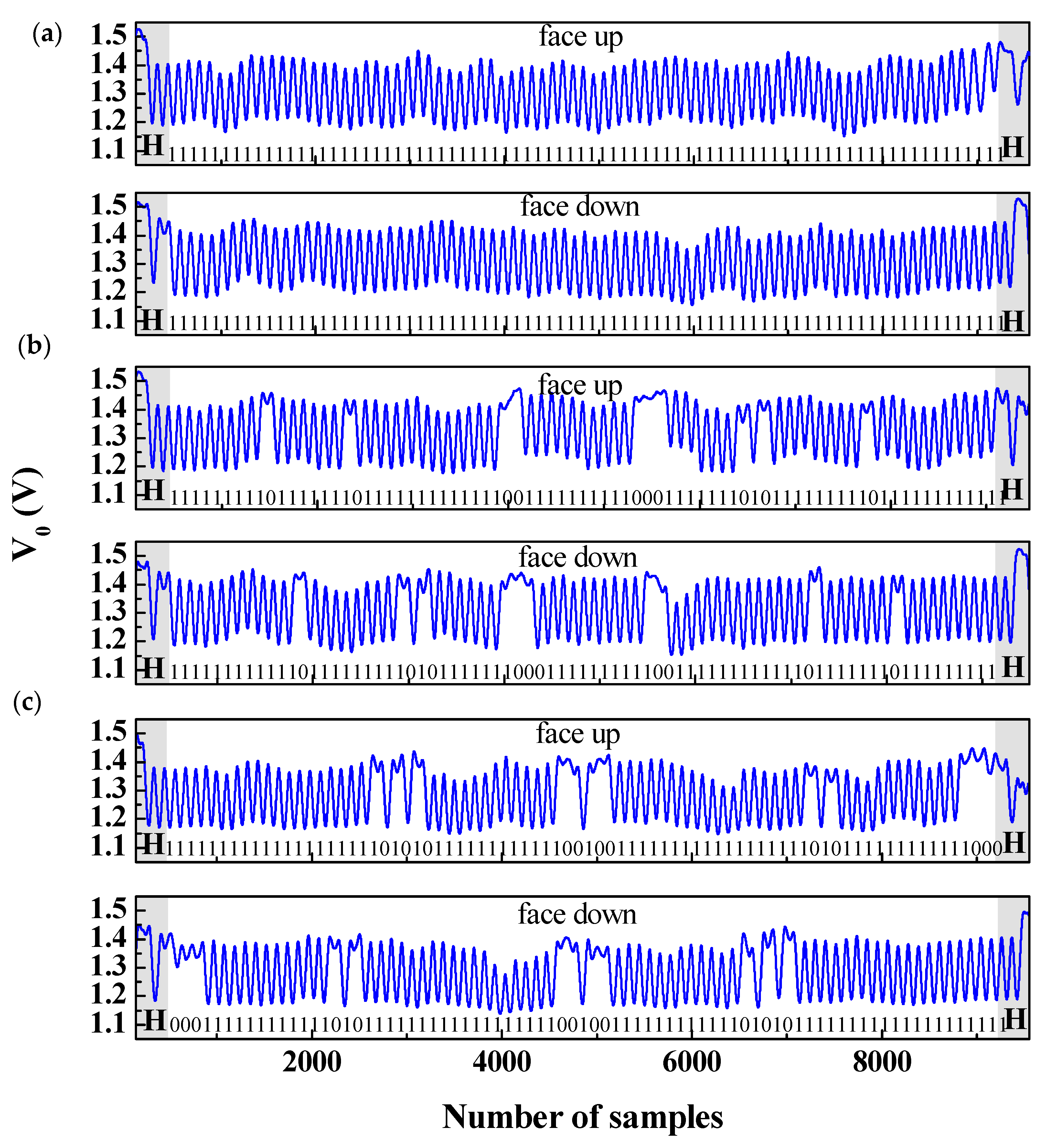
To illustrate the possibilities of the presented approach, we have obtained the ID code of the fabricated tag with all ID bits set to ‘1’. Figure 6 depicts the inferred code, with tag SRRs face up and down. Clearly, the code was correctly read regardless of the relative orientation between the tag and the reader. We then programmed the tag by cutting certain resonant elements. In particular, we considered the sequence (for the ID code) ‘111111111011111110111111111111100111111111100011111110101111111110111111111111’. In this case, tag reading provided the responses which are shown in Figure 6b, with tag SRRs face up and down, to demonstrate that the ID code is successfully obtained. Finally, we erased the tag and reprogrammed it with the ID code, ‘1111111111111111111101010111111111111001 00111111111111111111010111111111111000’. Results which were derived from the tag reading and are depicted in Figure 6c, revealed that, again, the ID code was correctly inferred, regardless of tag orientation. Indeed, we erased and reprogrammed several times, with a successful tag reading each time, indicating that the proposed system is robust. These results clearly suggest the following: (i) the number of achievable bits with this system is only limited by tag size; (ii) tag cost is very small as long as ordinary DIN A4 paper is used for tag substrate and a single layer of conductive ink suffices to correctly read the tags; (iii) tags can be programmed and erased as many times as needed. With these characteristics, the proposed chipless-RFID system is of interest for applications devoted to secure paper, in which, by printing the ID codes directly onto the document of interest, it is equipped with a secure code which is difficult to reproduce. Indeed, the codes can be photocopied, but tag reading requires a sophisticated system of the type shown in Figure 4. Moreover, it is possible to fabricate the tags through lamination, resulting in buried encoders difficult to reproduce. Banknotes, certificates, corporate documents, ballots, exams, medical recipes, etc. are different types of documents that may benefit of the proposed encoding system, providing them additional security against counterfeiting.
Future research will be to boost the number of resonant elements per unit length of the tag. Typically, in chipless-RFID systems, one benefit is the density of information per area unit. However, in the proposed chipless-RFID system, the tags exhibit an extremely long shape factor and, consequently, the interest is to accommodate the largest possible number of bits along the tag length (typically limited by the size of the document). Obviously, this can be achieved by increasing the resonance frequency of the SRRs (hence reducing its size), but this typically increases the cost of the associated electronics (harmonic signal generation, etc.). Therefore, the next challenge is to find novel resonator topologies, which are very short in the longitudinal direction of the tag chain, providing high sensitive tags that can be read through near-field coupling (sequentially) by means of a dedicated (adhoc) reader. Because linear half-wavelength resonators are very narrow, we are currently considering these resonant elements for tag implementation, where the idea is to transversely dispose the resonators along the tag. This strategy may increase the number of bits per unit length dramatically. However, it is necessary to find a suitable reader, which is able to reliably provide the ID codes in tags with extremely closed resonators. Work is in progress in this regard.
4. Conclusions
To conclude, 80-bit chipless-RFID tags inkjet printed on ordinary DIN A4 paper have been presented here for the first time. These tags are of special interest for secure paper applications, where the encoders can be directly printed on the document of interest. Reading by proximity (through near-field), as required in the reported chipless-RFID system, is not an issue in such applications, where the small distance between the tag and the reader may provide a certain level of confidence against spying, snooping, or eavesdropping. Additional advantages of the system are the high number of achievable bits (only limited by tags size), the low cost of the tags, and the possibility to program and erase the tags several times.
Author Contributions
C.H. and F.M. conceived the reported time-domain chipless-RFID approach; C.H., F.P. and J.M.-C. designed the active part of the reader and the tags; M.M. developed the electronics necessary for tag reading; A.N. fabricated the tags; C.H., F.P., M.M. and E.R. carried out the validation experiments; F.M. wrote the paper in collaboration with all the authors.
Acknowledgments
This work was supported in part by MINECO-Spain under Project TEC2016-75650-R and TEC2014-59679-C2-1-R in part by Generalitat de Catalunya under project 2017SGR-1159, in part by the Institució Catalana de Recerca i Estudis Avançats (who awarded Ferran Martín), and in part by FEDER funds. Cristian Herrojo acknowledges MINECO for supporting his research activity through the FPI grant BES-2014-068164.
Conflicts of Interest
The authors declare no conflict of interest. The founding sponsors had no role in the design of the study; in the collection, analyses, or interpretation of data; in the writing of the manuscript, and in the decision to publish the results.
References
- Preradovic, S.; Karmakar, N.C. Chipless RFID: Bar code of the future. IEEE Microw. Mag. 2010, 11, 87–97. [Google Scholar] [CrossRef]
- Preradovic, S.; Karmakar, N.C. Multiresonator-Based Chipless RFID: Barcode of the Future; Springer: New York, NY, USA, 2011. [Google Scholar]
- Karmakar, N.C.; Koswatta, R.; Kalansuriya, P.; E-Azim, R. Chipless RFID Reader Architecture; Artech House: Norwood, MA, USA, 2013. [Google Scholar]
- Perret, E. Radio Frequency Identification and Sensors: From RFID to Chipless RFID; John Wiley: New York, NY, USA, 2014. [Google Scholar]
- Rezaiesarlak, R.; Manteghi, M. Chipless RFID: Design Procedure and Detection Techniques; Springer: New York, NY, USA, 2015. [Google Scholar]
- Karmakar, N.C.; Zomorrodi, M.; Divarathne, C. Advanced Chipless RFID; John Wiley: Hoboken, NJ, USA, 2016. [Google Scholar]
- Finkenzeller, K. RFID Handbook: Radio-Frequency Identification Fundamentals and Applications, 2nd ed.; John Wiley: New York, NY, USA, 2004. [Google Scholar]
- Hunt, V.D.; Puglia, A.; Puglia, M. RFID: A Guide to Radio Frequency Identification; John Wiley: New York, NY, USA, 2007. [Google Scholar]
- Chamarti, A.; Varahramyan, K. Transmission delay line based ID generation circuit for RFID applications. IEEE Microw. Wirel. Compon. Lett. 2006, 16, 588–590. [Google Scholar] [CrossRef]
- Schüßler, M.; Damm, C.; Jakoby, R. Periodically LC loaded lines for RFID backscatter applications. In Proceedings of the Metamaterials, Rome, Italy, 22–24 October 2007; pp. 103–106. [Google Scholar]
- Schüßler, M.; Damm, C.; Maasch, M.; Jakoby, R. Performance evaluation of left-handed delay lines for RFID backscatter applications. In Proceedings of the IEEE MTT-S International Microwave Symposium, Atlanta, GA, USA, 15–20 June 2008; pp. 177–180. [Google Scholar]
- Shao, B.; Chen, Q.; Amin, Y.; Mendoza, D.S.; Liu, R.; Zheng, L.R. An ultra-low-cost RFID tag with 1.67 Gbps data rate by ink-jet printing on paper substrate. In Proceedings of the IEEE Asian Solid State-Circuits Conference, Beijing, China, 8–10 November 2010; pp. 1–4. [Google Scholar]
- Herraiz-Martínez, F.J.; Paredes, F.; Zamora, G.; Martín, F.; Bonache, J. Printed magnetoinductive-wave (MIW) delay lines for chipless RFID applications. IEEE Trans. Antennas Propag. 2012, 60, 5075–5082. [Google Scholar] [CrossRef]
- Tedjini, S.; Perret, E.; Vena, A.; Kaddout, D. Mastering the electromagnetic signature of chipless RFID tags. In Chipless and Conventional Radiofrequency Identification: Systems for Ubiquitous Tagging; IGI Global: Hershey, PA, USA, 2012. [Google Scholar]
- Preradovic, S.; Balbin, I.; Karmakar, N.C.; Swiegers, G.F. Multiresonator-based chipless RFID system for low-cost item tracking. IEEE Trans. Microw. Theory Technol. 2009, 57, 1411–1419. [Google Scholar] [CrossRef]
- Preradovic, S.; Karmakar, N.C. Design of chipless RFID tag for operation on flexible laminates. IEEE Antennas Wirel. Propag. Lett. 2010, 9, 207–210. [Google Scholar] [CrossRef]
- McVay, J.; Hoorfar, A.; Engheta, N. Space-filling curve RFID tags. In Proceedings of the 2006 IEEE Radio and Wireless Symposium, San Diego, CA, USA, 17–19 October 2006; pp. 199–202. [Google Scholar]
- Jalaly, I.; Robertson, D. Capacitively-tuned split microstrip resonators for RFID barcodes. In Proceedings of the European Microwave Conference, Paris, France, 4–6 October 2005; pp. 4–7. [Google Scholar]
- Jang, H.-S.; Lim, W.-G.; Oh, K.-S.; Moon, S.-M.; Yu, J.-W. Design of low-cost chipless system using printable chipless tag with electromagnetic code. IEEE Microw. Wirel. Compon. Lett. 2010, 20, 640–642. [Google Scholar] [CrossRef]
- Vena, A.; Perret, E.; Tedjini, S. A fully printable chipless RFID tag with detuning correction technique. IEEE Microw. Wirel. Compon. Lett. 2012, 22, 209–211. [Google Scholar] [CrossRef]
- Vena, A.; Perret, E.; Tedjini, S. Design of compact and auto-compensated single-layer chipless RFID tag. IEEE Trans. Microw. Theory Technol. 2012, 60, 2913–2924. [Google Scholar] [CrossRef]
- Vena, A.; Perret, E.; Tedjini, S. High-capacity chipless RFID tag insensitive to the polarization. IEEE Trans. Antennas Propag. 2012, 60, 4509–4515. [Google Scholar] [CrossRef]
- Girbau, D.; Lorenzo, J.; Lazaro, A.; Ferrater, C.; Villarino, R. Frequency-coded chipless RFID tag based on dual-band resonators. IEEE Antennas Wirel. Propag. Lett. 2012, 11, 126–128. [Google Scholar] [CrossRef]
- Khan, M.M.; Tahir, F.A.; Farooqui, M.F.; Shamim, A.; Cheema, H.M. 3.56-bits/cm2 compact inkjet printed and application specific chipless RFID tag. IEEE Antennas Wirel. Propag. Lett. 2016, 15, 1109–1112. [Google Scholar] [CrossRef]
- Rezaiesarlak, R.; Manteghi, M. Complex-natural-resonance-based design of chipless RFID tag for high-density data. IEEE Trans. Antennas Propag. 2014, 62, 898–904. [Google Scholar] [CrossRef]
- Bhuiyan, M.S.; Karmakar, N.C. A spectrally efficient chipless RFID tag based on split-wheel resonator. In Proceedings of the International Workshop on Antenna Technology: Small Antennas, Novel EM Structures, and Applications, Sydney, Australia, 4–6 March 2014. [Google Scholar]
- Nijas, C.M.; Deepak, U.; Vinesh, P.V.; Sujith, R.; Mridula, S.; Vasudevan, K.; Mohanan, P. Low-cost multiple-bit encoded chipless RFID tag using stepped impedance resonator. IEEE Trans. Antennas Propag. 2014, 62, 4762–4770. [Google Scholar] [CrossRef]
- Machac, J.; Polivka, M. Influence of mutual coupling on performance of small scatterers for chipless RFID tags. In Proceedings of the 24th International Radioelektronika Conference, Bratislava, Slovakia, 15–16 April 2014. [Google Scholar]
- Svanda, M.; Machac, J.; Polivka, M.; Havlicek, J. A comparison of two ways to reducing the mutual coupling of chipless RFID tag scatterers. In Proceedings of the 21st International Conference on Microwave, Radar and Wireless Communications (MIKON), Krakow, Poland, 9–11 May 2016. [Google Scholar]
- Herrojo, C.; Naqui, J.; Paredes, F.; Martín, F. Spectral Signature Barcodes based on S-shaped Split Ring Resonators (S-SRR). EPJ Appl. Metamater. 2016, 3, 1. [Google Scholar] [CrossRef]
- Hartmann, C.S. A global SAW ID tag with large data capacity. In Proceedings of the IEEE Ultrasonics Symposium, Munich, Germany, 8–11 October 2002; pp. 65–69. [Google Scholar]
- Saldanha, N.; Malocha, D.C. Design Parameters for SAW multi-tone frequency coded reflectors. In Proceedings of the IEEE Ultrasonics Symposium, New York, NY, USA, 28–31 October 2007; pp. 2087–2090. [Google Scholar]
- Harma, S.; Plessky, V.P.; Hartmann, C.S.; Steichen, W. Z-path SAW RFID tag. IEEE Trans. Ultrason. Ferroelectr. Freq. Control 2008, 55, 208–213. [Google Scholar] [CrossRef] [PubMed]
- Han, T.; Wang, W.; Wu, H.; Shui, Y. Reflection and scattering characteristics of reflectors in SAW tags. IEEE Trans. Ultrason. Ferroelectr. Freq. Control 2008, 55, 1387–1390. [Google Scholar] [CrossRef] [PubMed]
- Harma, S.; Plessky, V.P.; Li, X.; Hartogh, P. Feasibility of ultra-wideband SAW RFID tags meeting FCC rules. IEEE Trans. Ultrason. Ferroelectr. Freq. Control 2012, 56, 812–820. [Google Scholar] [CrossRef] [PubMed]
- Vena, A.; Perret, E.; Tedjini, S. Chipless RFID tag using hybrid coding technique. IEEE Trans. Microw. Theory Technol. 2011, 59, 3356–3364. [Google Scholar] [CrossRef]
- Vena, A.; Perret, E.; Tedjini, S. A compact chipless RFID tag using polarization diversity for encoding and sensing. In Proceedings of the 2012 IEEE International Conference on RFID, Orlando, FL, USA, 3–5 April 2012; pp. 191–197. [Google Scholar]
- Islam, M.A.; Karmakar, N.C. A novel compact printable dual-polarized chipless RFID system. IEEE Trans. Microw. Theory Technol. 2012, 60, 2142–2151. [Google Scholar] [CrossRef]
- Balbin, I.; Karmakar, N.C. Phase-encoded chipless RFID transponder for large scale low cost applications. IEEE Microw. Wirel. Compon. Lett. 2009, 19, 509–511. [Google Scholar] [CrossRef]
- Genovesi, S.; Costa, F.; Monorchio, A.; Manara, G. Chipless RFID tag exploiting multifrequency delta-phase quantization encoding. IEEE Antennas Wirel. Propag. Lett. 2015, 15, 738–741. [Google Scholar] [CrossRef]
- Rance, O.; Siragusa, R.; Lemaitre-Auger, P.; Perret, E. RCS magnitude coding for chipless RFID based on depolarizing tag. In Proceedings of the IEEE MTT-S International Microwave Symposium, Phoenix, AZ, USA, 17–22 May 2015. [Google Scholar]
- Rance, O.; Siragusa, R.; Lemaître-Auger, P.; Perret, E. Toward RCS magnitude level coding for chipless RFID. IEEE Trans. Microw. Theory Technol. 2016, 64, 2315–2325. [Google Scholar] [CrossRef]
- Herrojo, C.; Naqui, J.; Paredes, F.; Martín, F. Spectral signature barcodes implemented by multi-state multi-resonator circuits for chipless RFID tags. In Proceedings of the IEEE MTT-S International Microwave Symposium (IMS’16), San Francisco, CA, USA, 22–27 May 2016. [Google Scholar]
- Herrojo, C.; Paredes, F.; Mata-Contreras, J.; Zuffanelli, S.; Martín, F. Multi-state multi-resonator spectral signature barcodes implemented by means of S-shaped Split Ring Resonators (S-SRR). IEEE Trans. Microw. Theory Technol. 2017, 65, 2341–2352. [Google Scholar] [CrossRef]
- Gupta, S.; Nikfal, B.; Caloz, C. Chipless RFID system based on group delay engineered dispersive delay structures. IEEE Antennas Wirel. Propag. Lett. 2011, 10, 1366–1368. [Google Scholar] [CrossRef]
- Nair, R.; Perret, E.; Tedjini, S. Chipless RFID based on group delay encoding. In Proceedings of the IEEE International Conference on RFID-Technologies and Applications, Sitges, Spain, 15–16 September 2011; pp. 214–218. [Google Scholar]
- Feng, C.; Zhang, W.; Li, L.; Han, L.; Chen, X.; Ma, R. Angle-based chipless RFID tag with high capacity and insensitivity to polarization. IEEE Trans. Antennas Propag. 2015, 63, 1789–1797. [Google Scholar] [CrossRef]
- El-Awamry, A.; Khaliel, M.; Fawky, A.; El-Hadidy, M.; Kaiser, T. Novel notch modulation algorithm for enhancing the chipless RFID tags coding capacity. In Proceedings of the 2015 IEEE International Conference on RFID, San Diego, CA, USA, 15–17 April 2015; pp. 25–31. [Google Scholar]
- Vena, A.; Babar, A.A.; Sydanheimo, L.; Tentzeris, M.M.; Ukkonen, L. A novel near-transparent ASK-reconfigurable inkjet-printed chipless RFID tag. IEEE Antennas Wirel. Propag. Lett. 2013, 12, 753–756. [Google Scholar] [CrossRef]
- Herrojo, C.; Mata-Contreras, J.; Paredes, F.; Martín, F. Near-Field Chipless RFID Encoders with Sequential Bit Reading and High Data Capacity. In Proceedings of the IEEE MTT-S International Microwave Symposium (IMS’17), Honolulu, HI, USA, 4–9 June 2017. [Google Scholar]
- Herrojo, C.; Mata-Contreras, J.; Paredes, F.; Martín, F. Microwave encoders for chipless RFID and angular velocity sensors based on S-shaped split ring resonators (S-SRRs). IEEE Sens. J. 2017, 17, 4805–4813. [Google Scholar] [CrossRef]
- Herrojo, C.; Mata-Contreras, J.; Paredes, F.; Núñez, A.; Ramon, E.; Martín, F. Near-field chipless-RFID tags with sequential bit reading implemented in plastic substrates. Int. J. Magn. Magn. Mater. 2018, 459, 322–327. [Google Scholar] [CrossRef]
- Herrojo, C.; Mata-Contreras, J.; Paredes, F.; Martín, F. High data density and capacity in chipless radiofrequency identification (chipless-RFID) tags based on double-chains of S-shaped split ring resonators (S-SRRs). EPJ Appl. Metamater. 2017, 4, 8. [Google Scholar] [CrossRef]
- Herrojo, C.; Mata-Contreras, J.; Paredes, F.; Núñez, A.; Ramon, E.; Martín, F. Near-field chipless RFID system with high data capacity for security and authentication applications. IEEE Trans. Microw. Theory Technol. 2017, 65, 5298–5308. [Google Scholar] [CrossRef]
- Herrojo, C.; Mata-Contreras, J.; Paredes, F.; Núñez, A.; Ramon, E.; Martín, F. Near-field chipless-RFID system with erasable/programmable 40-bit tags inkjet printed on paper substrates. IEEE Microw. Wirel. Compon. Lett. 2018, 28, 272–274. [Google Scholar] [CrossRef]
Figure 1.
Sketch of the operating principle of the time-domain chipless-RFID system implemented on the basis of near-field and sequential bit reading.
Figure 1.
Sketch of the operating principle of the time-domain chipless-RFID system implemented on the basis of near-field and sequential bit reading.

Figure 2.
Layout of the SRR-loaded microstrip line of the reader (a), and transmission coefficients with and without oppositely oriented SRR on top of it (b). Dimensions are (in mm): l1 = 3.16, l2 = 3.35, s1 = 0.2, s2 = 0.2, W1 = 0.56, and W2 = 0.5. The considered air gap is 0.25 mm. The substrate of the line is the Rogers RO3010 with thickness h = 0.635 mm and dielectric constant εr = 10.2. The substrate of the tag is the Rogers RO4003C with thickness h = 0.204 mm and dielectric constant εr = 3.55. Figure extracted from Herrojo et al. [55]; printed with permission.

Figure 3.
Transmission coefficient at fc for different values of the air gap, corresponding to the reader loaded with perfectly aligned SRR. Figure extracted from Herrojo et al. [54]; printed with permission.
Figure 3.
Transmission coefficient at fc for different values of the air gap, corresponding to the reader loaded with perfectly aligned SRR. Figure extracted from Herrojo et al. [54]; printed with permission.

Figure 4.
Photograph of the reader.

Figure 5.
Photograph of the 80-bit tag fabricated on ordinary paper, with all bits set to ‘1’ and with header bits.
Figure 5.
Photograph of the 80-bit tag fabricated on ordinary paper, with all bits set to ‘1’ and with header bits.

Figure 6.
Measured envelope functions of the inkjet-printed 80-bit tag with the indicated codes. Because the envelope function has been inferred from a data acquisition system, the abscise axis is the number of samples. Note that there is no difference in the reading results between face-up and face-down tags. The codes are read in opposite directions for face-up or face-down tags, but this is indicated by the header bits and, therefore, there is no confusion regarding this aspect. (a) code with all bits set to ‘1’ logic state, (b) programmed tag and (c) reprogrammed tag.

© 2018 by the authors. Licensee MDPI, Basel, Switzerland. This article is an open access article distributed under the terms and conditions of the Creative Commons Attribution (CC BY) license (http://creativecommons.org/licenses/by/4.0/).
Share and Cite
MDPI and ACS Style
Herrojo, C.; Moras, M.; Paredes, F.; Núñez, A.; Ramon, E.; Mata-Contreras, J.; Martín, F. Very Low-Cost 80-Bit Chipless-RFID Tags Inkjet Printed on Ordinary Paper. Technologies 2018, 6, 52. https://doi.org/10.3390/technologies6020052
AMA Style
Herrojo C, Moras M, Paredes F, Núñez A, Ramon E, Mata-Contreras J, Martín F. Very Low-Cost 80-Bit Chipless-RFID Tags Inkjet Printed on Ordinary Paper. Technologies. 2018; 6(2):52. https://doi.org/10.3390/technologies6020052
Chicago/Turabian StyleHerrojo, Cristian, Miquel Moras, Ferran Paredes, Alba Núñez, Eloi Ramon, Javier Mata-Contreras, and Ferran Martín. 2018. "Very Low-Cost 80-Bit Chipless-RFID Tags Inkjet Printed on Ordinary Paper" Technologies 6, no. 2: 52. https://doi.org/10.3390/technologies6020052
Note that from the first issue of 2016, this journal uses article numbers instead of page numbers. See further details here.