Channel Estimation and Data Detection Using Machine Learning for MIMO 5G Communication Systems in Fading Channel


1
Department of Electronics and Telecommunication, JSPM’s Rajarshi Shahu College of Engineering, Pune 411033, Maharashtra, India
2
Department of Electronics and Telecommunication, Dr. D. Y. Patil Institute of Technology, Pimpri, Pune 411018, Maharashtra, India
*
Author to whom correspondence should be addressed.
Technologies 2018, 6(3), 72; https://doi.org/10.3390/technologies6030072
Submission received: 23 May 2018
/
Revised: 13 July 2018
/
Accepted: 26 July 2018
/
Published: 6 August 2018
(This article belongs to the Special Issue Machine Learning for 5G Communications and Beyond)
Abstract
:In multiple-input multiple-output orthogonal frequency-division multiplexing (MIMO-OFDM) systems, multi-user detection (MUD) algorithms play an important role in reducing the effect of multi-access interference (MAI). A combination of the estimation of channel and multi-user detection is proposed for eliminating various interferences and reduce the bit error rate (BER). First, a novel sparse based k-nearest neighbor classifier is proposed to estimate the unknown activity factor at a high data rate. The active users are continuously detected and their data are decoded at the base station (BS) receiver. The activity detection considers both the pilot and data symbols. Second, an optimal pilot allocation method is suggested to select the minimum mutual coherence in the measurement matrix for optimal pilot placement. The suggested algorithm for designing pilot patterns significantly improves the results in terms of mean square error (MSE), symbol error rate (SER) and bit error rate for channel detection. An optimal pilot placement reduces the computational complexity and maximizes the accuracy of the system. The performance of the channel estimation (CE) and MUD for the proposed scheme was good as it provided significant results, which were validated through simulations.
1. Introduction
In the past two decades, the use of wireless communication has exceeded the use of personal communication or human-to-human (H2H) communication. Thus, we need to achieve high spectral efficiency, update user experience and reduce latency in this widely-used wireless communication. Nowadays, the information connectivity for the machine-to-machine (M2M) devices is placed under high demand, which plays a major factor in the next generation [1]. A new type of traffic that has arrived in the cellular communication system by interconnecting the large devices is known as the Internet-of-Things (IoT) [2].
The implementation of gigabit ethernet (GigE), Internet of Things (IoT), vision internet and heterogeneous networks (Hetnets) has been aided by the 5th generation (5G) networks [3]. Of these, the IoT technology supported by M2M has modernized applications, including agriculture, transportation, tracking, metering, e-health and so on. Some of the design aspects related to massive M2M infrastructures include the multiple access system [4], sharing of the resources and the different parts of networking [5].
Multi-user detection (MUD) is a receiver technology dedicated to the detection of all the interfering signals via compressive sensing (CS) [6]. If more devices are not in an active state (user activity is low), the transmitting signal vector has a sparse property due to a large number of non-zero elements. Therefore, the decoding of the transmitted signal becomes a CS problem [7]. The long-term evolution is appropriate for a system that provides a small number of high activity of users. However, this shifts for machine-type communication (MTC) where a higher number of users with fewer activity sporadically sends a small number of packets [8].
Recently, researchers have focused more on OFDM systems compared to the existing air-interface techniques due to its low complexity. In OFDM systems, the subcarriers are sent through multiple channels, which permits ease of equalization in the case of low complexity during the implementation.
Spyridon et al. [9] considered various types of noises, such as Additive white Gaussian noise (AWGN), phase noise (PN), Rayleigh fading, Rician fading and Doppler shift with the turbo coding technique. The simulation platform consisted of three modules (transmitter, channel and receiver). In the transmitter module, turbo coding is performed, which makes the system more immune to the effects of noise with excellent BER results. The channel model is constituted by multipath fading, Doppler shift, AWGN and PN.
In reference [10] the simulation is carried under various noise types, such as complex Rayleigh fading, complex Rician noise, AWGN and phase noise.
Spyridon et al. [11] split an information stream into multiple frequency carriers, which joins OFDM in the simulation platform with turbo codes to find a better turbo scheme compared to a typical parallel concatenated convolutional codes and serial concatenated convolutional codes (PCCCs and SCCCs) are a class of Forward error correction codes suitable for turbo decoding and a convolutional encoder.
Some of the evolutionary algorithms (EAs) that have been useful for both CE and MUD investigation includes repeated weighted boosting search (RWBS), differential evolution algorithms (DEAs) and fuzzy adaptive differential evolution (FADE) algorithm [9,10]. Normally, the continuous search space is considered for the CE problem and a discrete search space for the MUD optimization problem.
Multiuser-MIMO (MU-MIMO) broadcast approaches are frequently used to improve the spectral efficiency. The quality of transmitting pre-coding to dominate the multiuser interference becomes degraded because of the coarse knowledge of channel state information (CSI) at the transmitter. Therefore, the interference from co-scheduled user equipment can affect the system throughput.
Park et al. [12] proposed that the channel estimation can be used to subsequently discover the quality of MU-MIMO systems as a refreshing channel assessment approach which employs reliable soft symbols. They collect reliable data tones from both desired and interfering users related to the conclusion and apply them as pilots for re-evaluation of the channel. The channel assessment and data decoding are obtained iteratively when the channel and data symbols become joined. These two processes utilize the familiar expectation maximization algorithm.
Zhou et al. [13] considered the problem of CE for a mm-wave system with one RF chain used at the BS and mobile station (MS). Being different from most existing studies that examined narrowband channels, they considered the estimation of wideband mm-wave channels with frequency selectivity, including the angles of arrival/departure, time delays and fading coefficients. In their proposed method, the two stages compressed the sensing algorithm with the low-rank matrix, which allows the sampling process to be performed. After this, the sparse recovering stage occurs, which allows us to estimate the mm-wave channel. Hence, their proposed method has the potential to achieve lower sample complexity and overhead reduction.
Bao et al. [14] considered multiple access and broadcast channels to examine the error performance of multidimensional constellations. Specifically, the closed-form expression for the pairwise error probability (PEP) in the joint maximum likelihood detection was provided for multiuser signaling. The arbitrary numbers of users and multidimensional signal sets were assumed, while the simulation results show the importance of the multidimensional constellation. Furthermore, a useful average symbol error probability was also obtained through the upper bound with the results from the analysis being more accurate.
Olfat and Bengtsson [15] considered IoT-based on 5G or machine type communication (MTC), in which the low-power transmitter communicates with the high-quality receiver. However, they combine the joint maximum-likelihood estimation of the channel and the multi-path fading OFDM systems to investigate the probability of the receiver-side compensating for the transmitter RF impairments. In particular, they proposed an alternative optimization algorithm, which uses frequency-domain block-type training symbols to prove that their algorithm is able to solve the two alternate algorithms. After this, they calculated the Cramer-Rao lower boundary, which showed that the proposed estimator provides a high signal-to-noise ratio.
Fixing the packet collision impairment in both the Advocates of Linux Open-source Hawaii Association (ALOHA)-based networks and the random access networks is the main aim for reducing performance degradation. Bartoli et al. [16] proposed a novel MUD scheme, which is used to separate the collided signals to enable multiple packet reception capabilities in random access schemes. The performance of Markov chain approach is analytically derived and optimized in terms of network throughput, before being compared with that of different alternatives.
At BS, each user’s uplink pilots are also transmitted due to the absence of CSI during the estimation of the channel [17,18,19]. One of the optimal detectors in the MUD is the maximum likelihood (ML) method, although it is difficult to use this to achieve the exponential complexity. The zero-forcing or null steering detector [20], the minimum mean square error (MMSE) detector in M2M [21] and the maximum a posteriori (MAP) or marginal likelihood detector [22] are some of the sub-optimal MUD detectors that can be used for situations with less complexity. The main objective of the multiuser detection involves the study of strategies to demodulate the digital information sent simultaneously by several transmitters, which share a multiple-access channel. Common channels that are encompassed by this general model include up-link satellite channels, local area networks and radio networks. The well-appreciated MUD algorithms simultaneously detect the transmitted symbols of all active user terminals. However, they know which terminals are active and which user must be inactive. The existing algorithms only detect the active users in MIMO-OFDM when the user activity factor is known and small. However, this user activity factor is usually unknown and could be large in practice, which makes it difficult to employ the multiuser detection (MUD). In the frequency-selective channel, the resource splitting between pilot and data symbols within the channel’s coherence bandwidth causes a trade-off between the channel estimation quality and bandwidth available for data transmission. Sparsity has been used for estimating the parameters of communication systems. Basically, noise and interference are the major issues in the MIMO OFDM systems. To overcome these issues, the multiuser detection method along with channel estimation is used in MIMO-OFDM.
The main aim of the paper is to develop the fast MUD and CE algorithm in MIMO-OFDM for high-speed connectivity and interference cancellation. The proposed method aims to provide high reliability with a focus on high-speed connectivity fora small number of user equipment per BS. The analysis for the multipath Rayleigh fading channel in the multi-input multi-output orthogonal frequency-division multiplexing (MIMO-OFDM) systems has an issue of frequency selective channel estimation. MIMO-OFDM is the dominant air interface for 4G and 5G broadband wireless communications. In order to avoid interference and concentrate on the active users of the network, MIMO-OFDM has more advantages in multiuser detection. The detection of the active users in the multi-access system is performed by the machine learning approach when the activity factor is unknown. To evaluate the unknown activity factor at a high data rate, the sparse based k-nearest neighbor (SKNN) classifier is used. The BS receiver explores the active users and decodes their data. In activity detection, both pilot and data symbols are applied. For optimal pilot placement, a novel pilot allocation method is projected, which decreases the common relation of the measurement matrix. The optimal selection of pilot patterns with the help of cat swarm optimization are used to ultimately verify the sparse channel evaluation and to reduce the computational complexity. The effect of both noises and MAI is controlled by both the CE and turbo/decoder technique. It decodes the received signal properly without any errors from the channel. The reduced BER and SER are calculated to compare the performance in the proposed framework. The description of the nomenclature for the entire paper is described in Table 1.
2. Materials and Methods
2.1. Multiuser MIMO-OFDM System
MIMO-OFDM system contains T number of antennae having subcarrier frequencies in the BS of the transmitter side. The system considers I number of MSs and all users simultaneously transmit their data streams to the BS, which can be denoted as . Furthermore, every user sends a unique ID along with the signal. Therefore, the user sends the data and pilot sequence as the inputs to the MIMO-OFDM system.
The MUD and CE process is carried out on the receiver side for interference cancellation and noise reduction. An important aim of the suggested approach is to find the error bits among the received signals and correct them. The BER of the overall system is reduced in the joint MUD and CE. The received symbols and pilot over all subcarriers are collected at the receiver end for interference cancellation and noise reduction. The transmitted symbols are simultaneously received by the BS antenna. The MUD methods are used to separate the signals of various MSs depending on their unique user-specific channel impulse responses at BS. The frequency separation is measured in terms of the coherence bandwidth. The non-line-of-sight (NLOS) error is the major issue during transmissions that interferes with a path that is partially obstructed. The NLOS error exists if there is no visual line of sight (LOS) between the transmitting and receiving antennae. In the NLOS propagation case, it has a Rayleigh distribution. The uncorrelated fading experienced between the signal and the gain may be following a Rayleigh distribution.
2.1.1. System Model
We assumed a frequency-selective Rayleigh fading multipath channel between the sender side and receiver side. The BS has NR receiver antennae with NI users. Every antenna has a single omni-directional antenna. The number of antennae LA used is greater than the number of users I. The signal along with the additive white Gaussian noise (AWGN) and MAI are considered as the inputs.
Let us consider the stream of bits for I users. The number of transmitting antennae for I users is denoted as , where . Therefore, the input stream can be represented as , where is the transmitting antenna. First, the stream of bits can be encoded using the turbo encoder T. After encoding, the bitstream can be represented by , which can be passed through a pseudo-random interleaver. This interleaver is usually based on the block interleaving scheme, which is used with turbo codes to scramble the input sequence. The output of the interleaver I can be represented as . The output stream from the interleaver is collected as blocks of log2M bits. After this, the blocks are modulated as M-ary quadrature amplitude modulation (M-QAM) symbols.
The modulated output can be denoted as . That signal can be converted into parallel bits using the serial-parallel (S/P) converter. We assumed that the OFDM system has N subcarriers. After this, the OFDM symbols are obtained after embedding the pilot symbols. The transmitted bit stream of data is comprised of user information and pilot symbols. The transmitted user data is represented as , , and the pilot symbols are denoted as, , where and . In this case, the subcarrier K will be in the range , P subcarriers are assigned for pilot symbols and n represents the OFDM symbol index. The receiver knows about the pilot symbols of the frequency domain (FD) and its channel allocation for the initial CE. After this, the FD modulated signal can be converted into the time domain (TD) modulated signal in the K-point IFFT. The resultant sequence of bits is transmitted to the receiver side through the MIMO channel after inserting the cyclic prefix (CP) of samples. The length of CP must be chosen as , where represents the length of CIR. When transmitting the signal through the channel, the signal is contaminated with the AWGN and interference channel.
The received signal can be represented as . The number of receiving antennae for the j-th output is represented as , where . The signal is received in serial form and the CPs are discarded from each OFDM symbol. Following this, it is fed into the K-point FFT for FD representation at the receiver side. is the received signal for the k-th subcarrier in the receiver. The antenna element of n-th OFDM symbol is given by:
where during the s-th OFDM symbol period, is AWGN, while represents the K-sparse channel impulse vector and FD channel transfer function of i-th user and the receiver antenna element, which holds the CIR coefficients. The impulse vector for the K-sparse channel is represented as:
The received data can be arranged in a column vector for each receiver antenna, which hosts the subcarrier signals :
The transmitted data of each user in a diagonal matrix are represented as:
where represents the diagonal elements for I users. The next section deals with the optimally designed pilots to ensure that all the correlation matrices are diagonal.
2.1.2. Model for the Optimization Problem
The pilot symbols of the i-th transmitter are:
where is the partial FFT matrix and is an impulse vector of the K-sparse channel.
The partial FFT matrix can be represented as:
where a = 1, 2, …P; b = 1, 2, …L; and .
The mutual coherence for the sparse signal of the measurement matrix is as follows:
The optimization problem can be defined for CE by minimizing the mutual coherence.
2.2. Proposed Joint CE and Turbo MUD
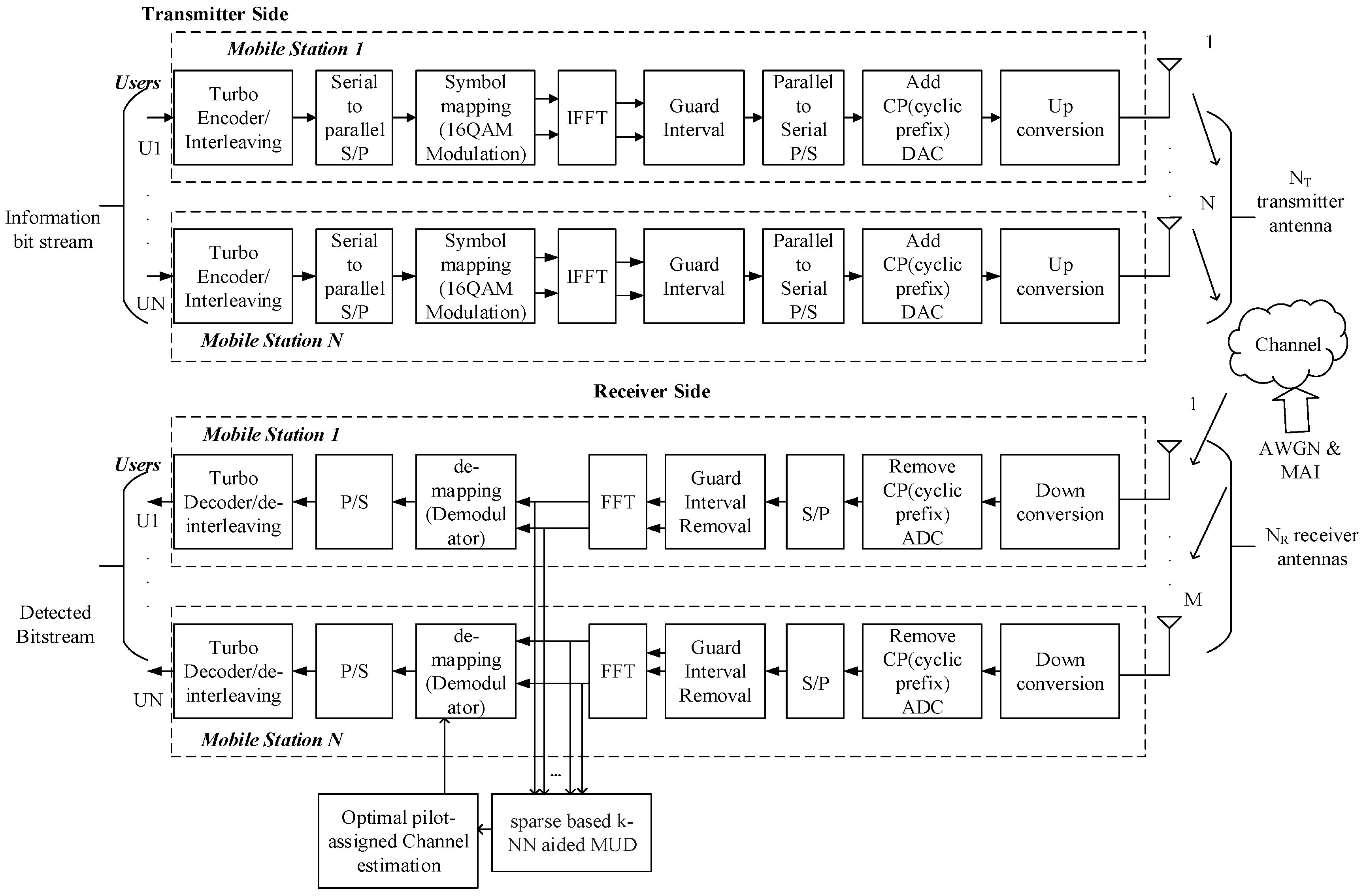
The signals are transmitted into blocks and it is transmitted using the NT transmitter antenna. The signal is converted into blocks before transmitting the data, which are transmitted along with the CP. At the transmitter and receiver sides, the inverse FFT and FFT are used for data transmission. First, the input data streams are transmitted to the turbo encoder at the transmitter side to obtain the encoded signal and this encoded signal is conveyed in blocks. After this, the encoded signal is fed to the interleaver. Following this, the output from the interleaver is given to the 16-QAM modulator block to produce symbol blocks. We obtain the frequency domain symbol vector after N-point DFT operation. Furthermore, the subcarrier mapping, IFFT and cyclic prefix (CP) operations are conducted for the data symbol vector for all subcarriers. The same process is repeated at the recipient side. MAI can reduce the performance of MIMO-OFDM systems. The detailed architecture is illustrated in Figure 1.
2.2.1. Sparse Based k-NN for Active User Detection
During the uplink transmission, users transmit the information to the central BS. Basically, all users are not dynamic during a given time interval so communication may be sporadic in nature. If we only predict the active users for transmission, the user can achieve high-speed internet connectivity. The transmitted signal vector is sparse and thus, the reconstruction of this transmitted sparse signal becomes a CS problem. In order to be suitable for a dimensional feature space, we constructed a bit mapping for the candidate bits. After mapping the received bits into a feature space, we distinguished the error bits and the right ones based on some properties. At the BS, the candidate bits are used in the training database. There is a large number of unknown bits that arrive at the same time. Therefore, the sparse based k-nearest neighbor (SKNN) algorithm is used to predict both the right and wrong bits. The prediction scheme is introduced for the detection of uplink data reception. The rights bits are taken as the active users from the BS, which is given to the receiver antennae. The prediction is conducted using the k-NN machine learning algorithm. The important aim of this paper is to detect the received signal from the channel matrix H.
specifies the complex channel matrix between the central BS and K devices. We can determine the active users for the i-th symbol in b according to:
where M is the QAM modulation alphabet.
We considered the received signal bits at the BS as I = (I1, I2, I3, …, Ip) where p is the user dimensionality of the input space. Each input variable can be considered as a dimension of a p-dimensional input space. The complete set of received signal bits is simply stored in the “training phase”.
First of all, we must determine the parameter l, where 0 ≤ l ≤ 1. The parameter l determines the number of nearest neighbors to determine the count of active users at a given time. After this, we computed the distance between the query instance and all the training samples. The BER and channel capacity is used as the query instance (QR) to predict the right and wrong bits for every user I within the limit of l < 0.5.
The amount of error bits in the information stream per unit time is defined as the BER over the communication channel. BER is given as:
where is the total number of error bits and is the total number of bits sent.
A non-linear function, which is called the ergodic capacity, is used for maximizing the capacity under fixed subcarrier rate. It can be defined as:
where represents the signal-to-noise ratio (SNR), N is the total number of bits sent and B is the bandwidth of the received signal. This is the average instantaneous capacity for an AWGN channel with SNR.
The distance D (I, QR) between the two vectors I and QR is defined as their usual vector distance in Euclidean units:
Finally, based on the kth minimum distance, the nearest neighbors are determined in order to sort the distance. A neighbor has the minimum distance, which can be used to predict the active users. Hence, we collected the number of nearest neighbors as the active users. The predicted users (a right bit belongs to a specific user) are finally taken as the active users and the receiver antennae receive the k number of active users. After this, the received bits are given to the Turbo MUD/decoder, which mitigates the effect of both noise and MAI.
2.2.2. Cat Swarm Optimization (CSO) Based Channel Estimation (CE)
In MIMO-OFDM system, the pilot pattern can be optimized by minimizing to enhance the execution of the system. Due to the existence of strong interference, conventional methods (minimum mean-square error (MMSE) and least-square (LS)) has poor system performance. The pilot sequence becomes contaminated because of MAI. The performance of the channel is also generally limited due to pilot tone selection. To improve the performance, an optimal pilot pattern selection using the cat swarm optimization (CSO) algorithm is applied and thus, it improves the accuracy of sparse CE. During CE, the pilots are optimally selected using the CSO algorithm with the fitness of delay and phase, which reduces the mutual coherence. The two modes collected in it are the tracking and seeking modes. This algorithm identifies the global solutions compared to another existing optimization algorithm. We assumed that all the model parameters of the channel are associated with both the transmitter and receiver. Therefore, no feedback channel is necessary to define its error variance and no feedback is required for the encoder. Algorithm 1 describes the CSO based optimal pilot pattern for reducing the largest element in mutual coherence.
The basic idea behind the search algorithm is to select the suboptimal pilot pattern of minimum mutual coherence from the set of pilot indices Ω = {1, 2, …, N}. To reduce the effect of multi-access interference (MAI), the active users should be continuously detected. For this activity detection, the pilot and data symbols are considered. In the measurement matrix calculation of optimal pilot placement, the optimal pilot allocation method is suggested to select the minimum mutual coherence. Therefore, for MUD, the mutual coherence should be minimized. The major objective is to minimize the mutual coherence during pilot allocation in MIMO-OFDM systems.
In order to tackle the optimization problem, the CSO optimization algorithm is utilized, which optimally selects the minimal value and hence, the system attains CE.
We designated the set of pilot locations and the set of pilot distances as with . The first step produces the pilot patterns and the mutual coherence , but all the elements in the cannot achieve all their minimum levels at the same time. We estimated the fitness value for each N cat and the best fitness value of cat acts as the global best (gbest).
The fitness for the individual function can be defined as:
If the condition of is satisfied, this points to a higher mutual coherence, while specifies the pilot symbols collected from all subcarriers.
| Algorithm 1: Pseudo code for the CSO based optimal pilot pattern for reducing the largest element in mutual coherence. | |
| Initialization. Let different parameters for the population size be Ps = 100, the length of all the individuals is Len = P − 1 and the maximum generation is Mg. Create the initial population randomly Φi, where i = 1, 2, … Ps. After this, compute the fitness for the initial population individually. | |
| 1: Produce N-cats, which represents pilot symbols. | |
| 2: Cats have M-dimensional space and arbitrarily gives a range of values for the maximum velocity of each cat. | |
| 3: By applying the position of cats in the fitness function, evaluate the fitness value for each cat. It represents the finest position of the cat (xbest) by calculating the mutual coherence of each pilot sequence. | |
| 4: Move the cat according to their modes, apply the process of the seeking mode if the cat is in seeking mode. Otherwise, use the tracing mode process. | |
| 5: Activate the tracing mode process again by selecting the number of cats and according to the MR, the seeking mode can be applied to other cats. | |
| 6: To terminate the program, check if the termination condition is satisfied. Otherwise, repeat step 3 to step 6. | |
| Output: The optimal pilot pattern Ψ. | |
3. Results
The performance estimation of the suggested method is in the fading channel. The bandwidth of the system is 5 MHz with 32, 128 and 512 subcarriers. A MIMO-OFDM with dimensions of 4 × 4 is considered for performance evaluation. The input simulation parameters are given in Table 2. The simulation results for the suggested method are demonstrated in terms of the BER, SER and MSE compared to the signal-to-noise ratio (SNR).
When compared to existing algorithms, the loss due to the joint MUD and CE is decreased. The suggested MIMO-assisted multi-user detection algorithm compromises and attains a greater throughput than the traditional MMSE scheme. The optimum pilot pattern is selected through a mutual coherence of 0.1872.
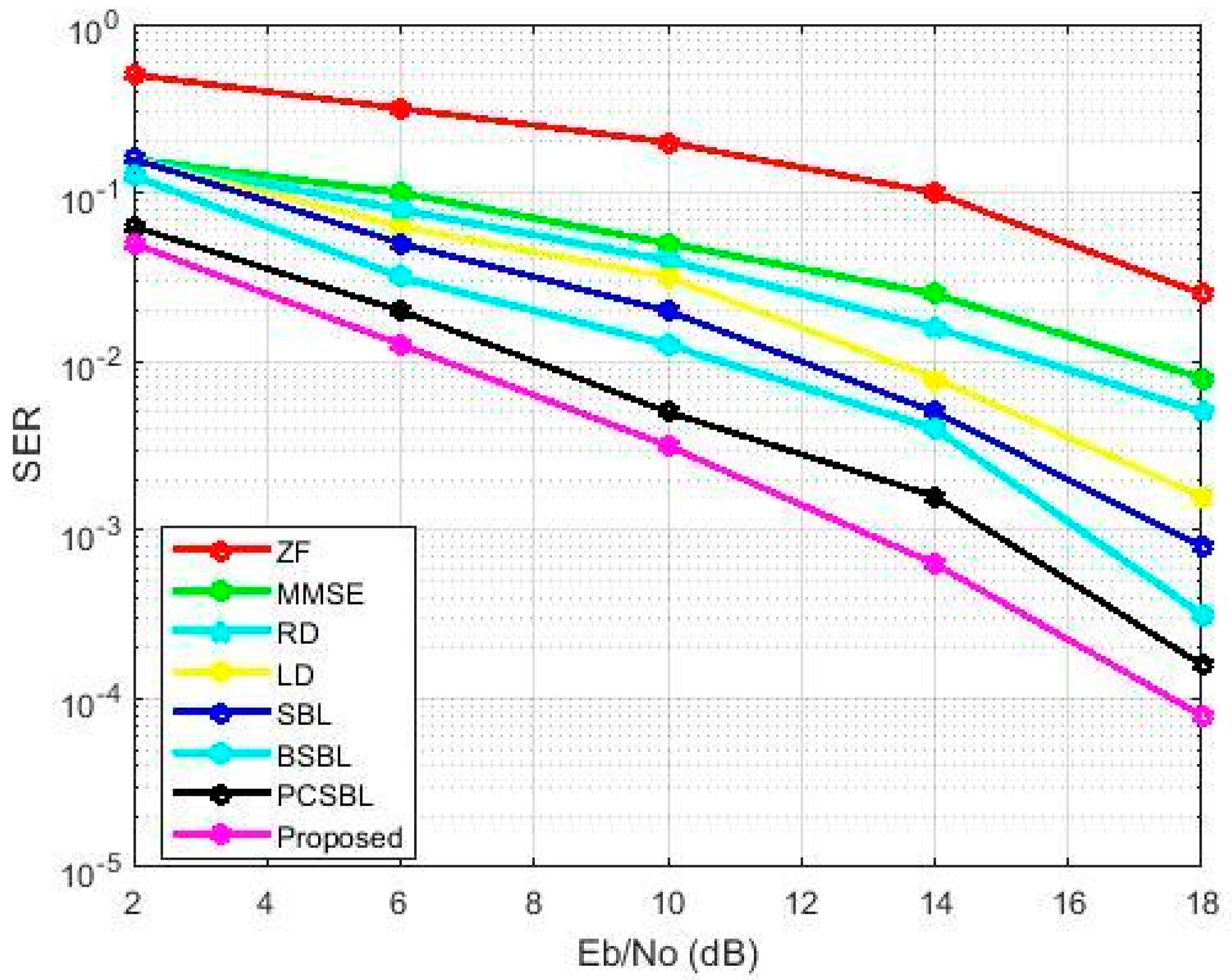
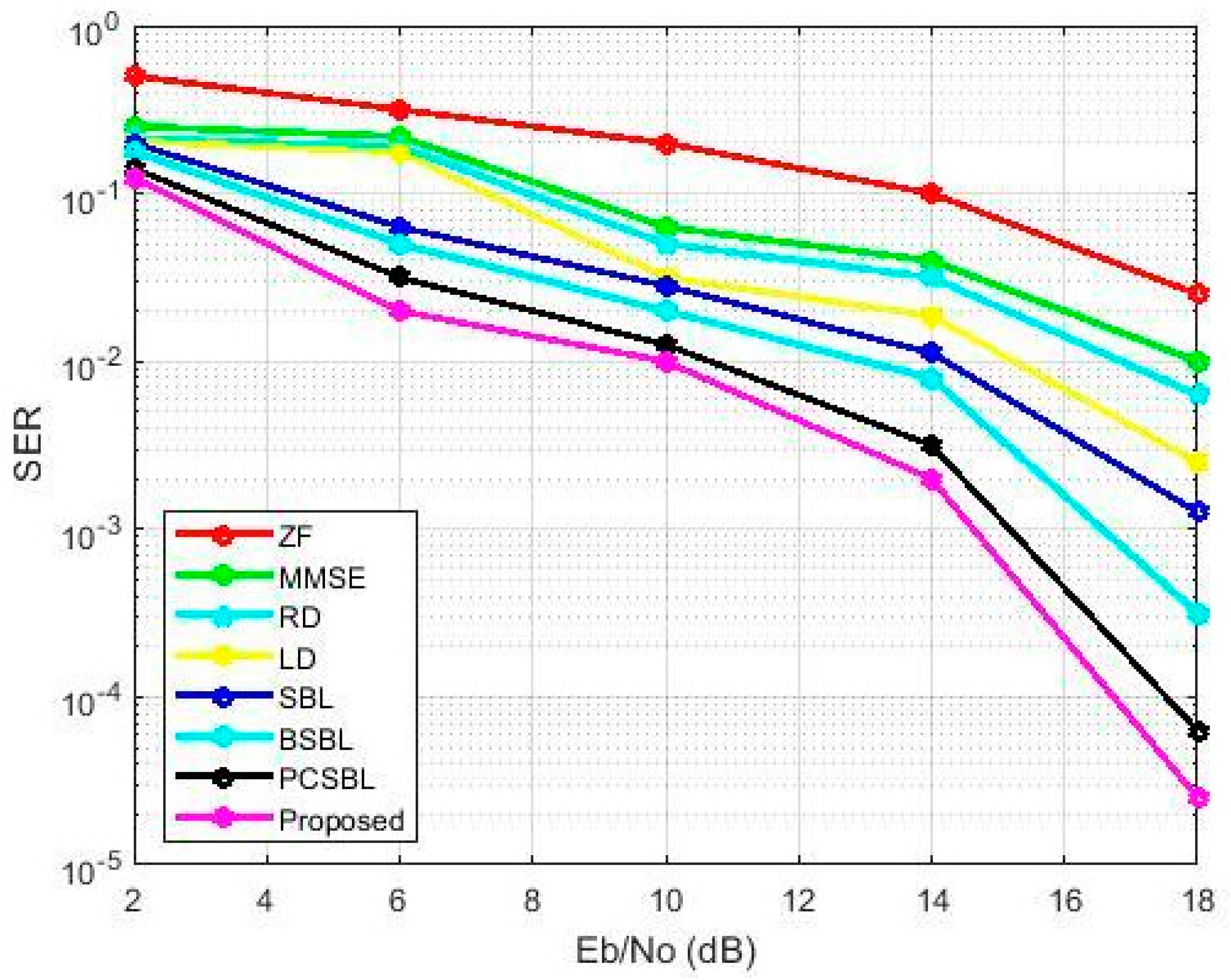
The performance evaluation of SER can be illustrated in Figure 2 and Figure 3 for 20 users and 100 users. The comparative analysis of various MUD techniques presented in [23] is compared with the existing approach. SER is minimized for our proposed approach. The proposed technique is compared with the existing zero-forcing (ZF) detector, minimum mean square error (MMSE) detector, ridge detector (RD), lasso detector (LD), sparse Bayesian learning (SBL), block sparse Bayesian learning (BSBL) and pattern-coupled sparse Bayesian learning (PCSBL). The SER is calculated based on the detected errors. The low and high users’ activity is detected by finding the error bits. The graph significantly shows that the proposed method has a minimum SER in terms of the SNR (dB) for 20 and 100 users. The rate of SER is declined with an increase in SNR. BER can estimate the altered bits transmitted over the channel. The same problem discussed in [23] for activity detection is used but the performance of the proposed approach outperforms their methods (SBL, BSBL and PCSBL). Furthermore, it is not well suited for MAI compared to our proposed methods.
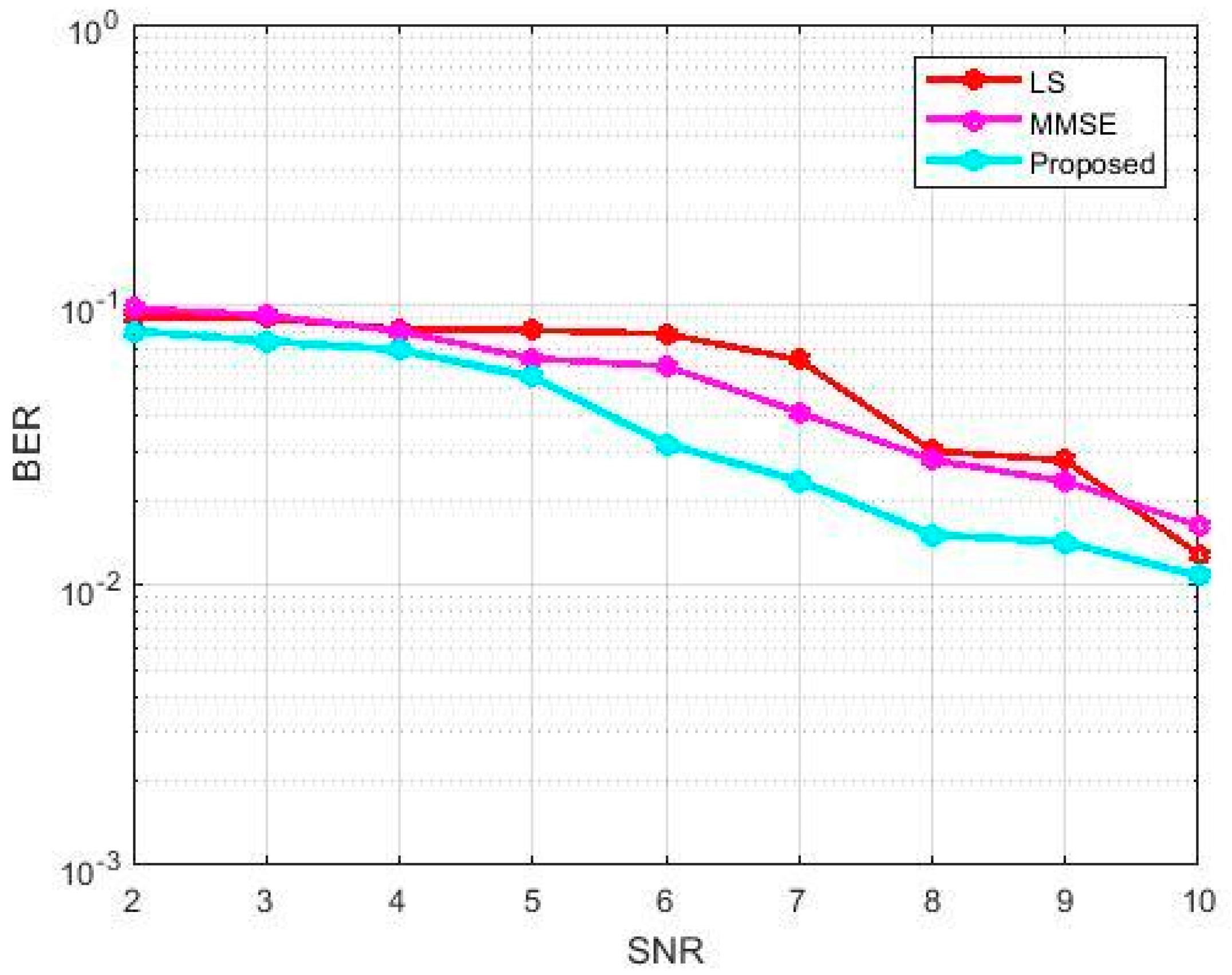
The BER and SNR performance of LS and MMSE in Figure 4 shows the efficiency of CE. The CSO based optimization for attaining the minimized mutual coherence attains a minimized BER in terms of SNR compared with LS and MMSE. The existing comparison chart for BER is presented in reference [13].
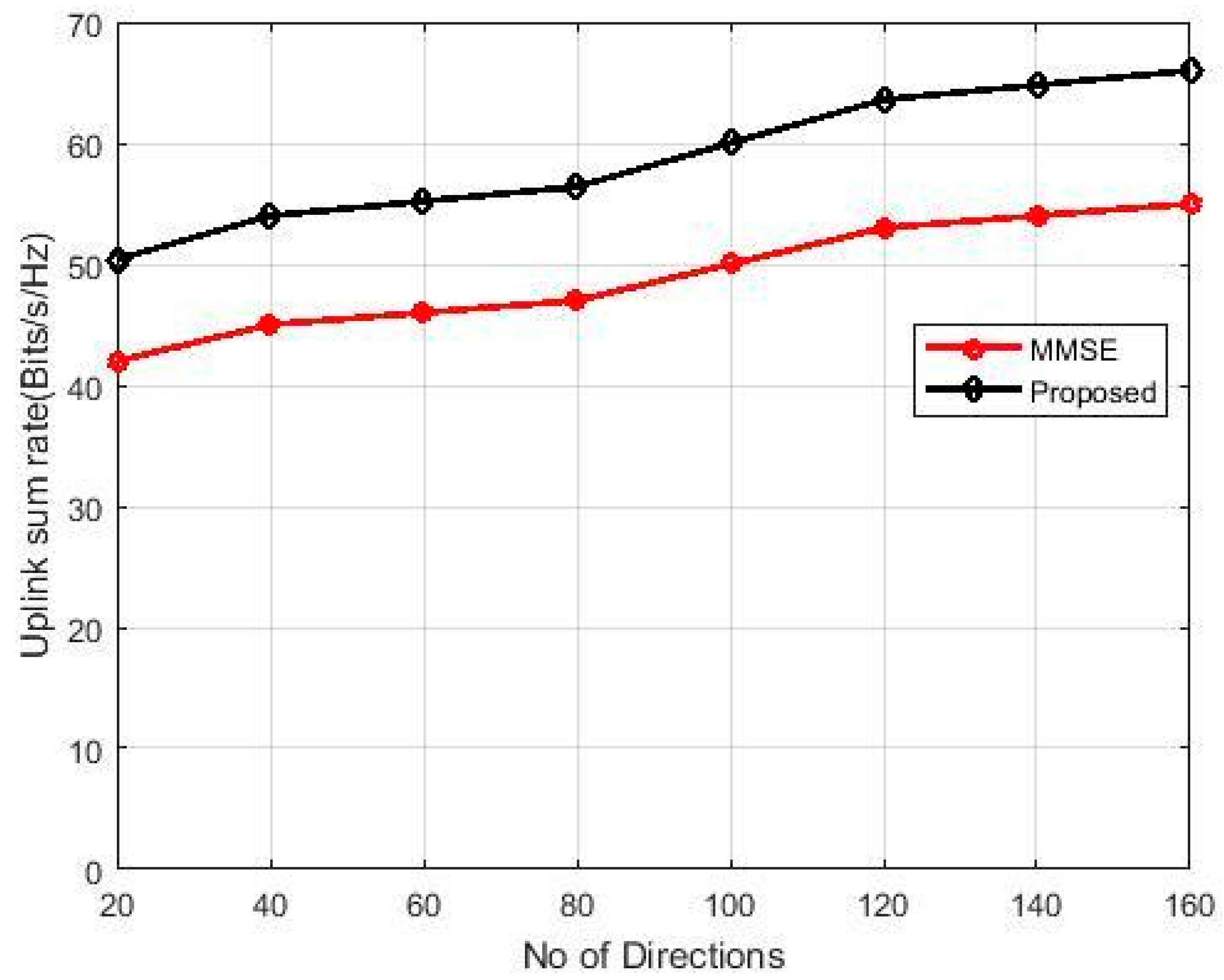
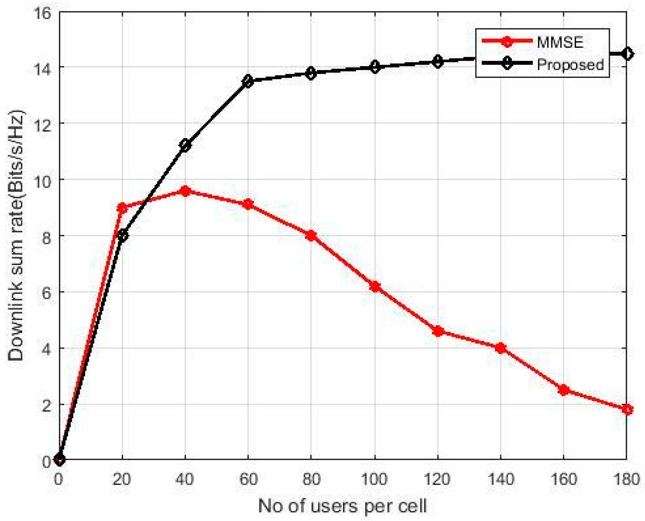
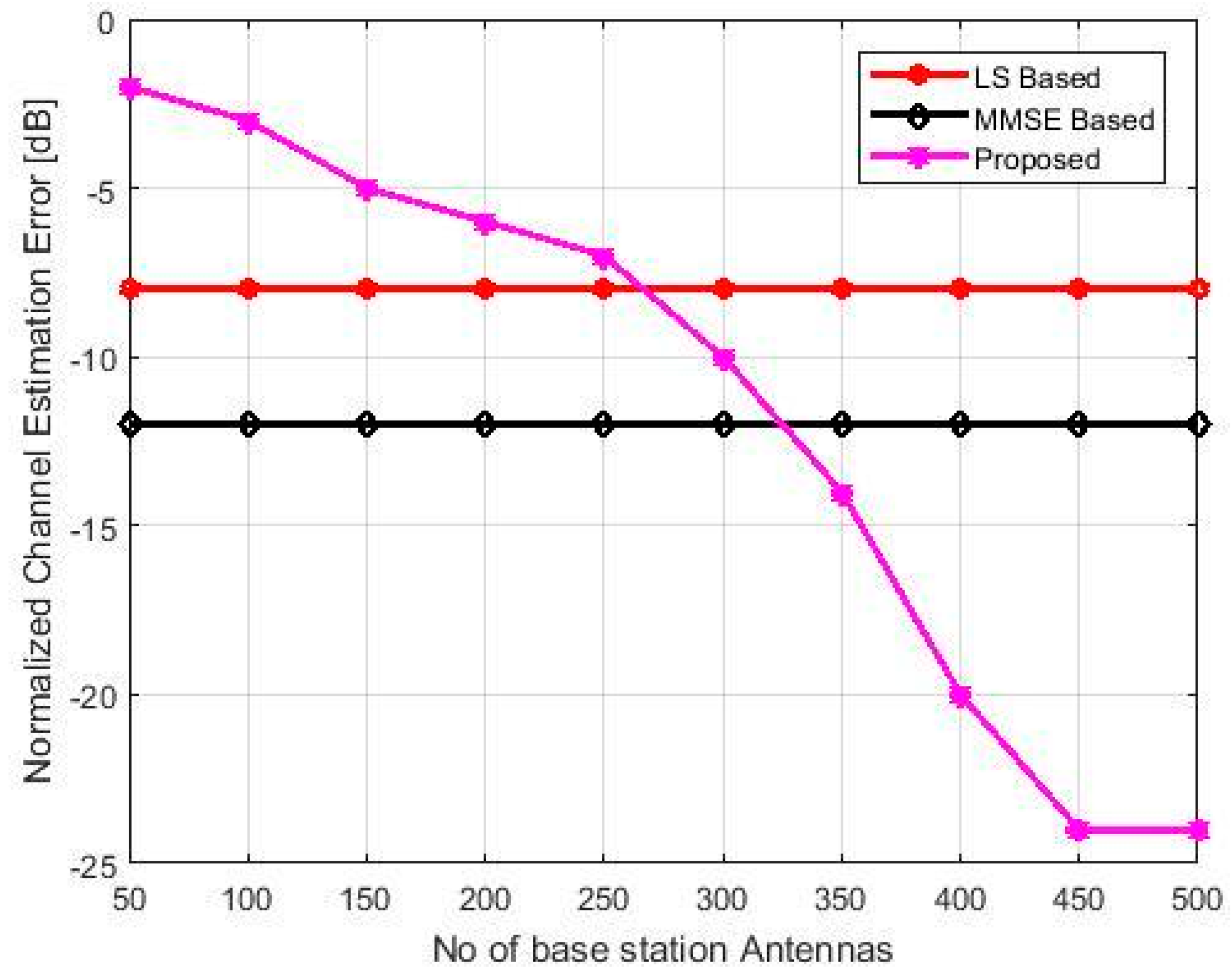
The comparative analysis of the proposed work represented in Figure 4, Figure 5, Figure 6 and Figure 7 and the existing works are taken from reference [15]. The entire bandwidth of the channel is divided by 128 subcarriers with a symbol duration of 160 μs in the LS based pilot allocation. To avoid inter-symbol interference, we chose 40 μs for the delay spread in the channel, 40 Hz for the Doppler shift and 100 Hz of the Doppler spread. The simulations were completed for two dissimilar channels (delay and power profiles). The results were estimated for 500 OFDM simulated blocks based on each antenna. The average SNR was less than or equal to 25 dB and the average delay was 260 ns for 10 to 20 iterations. Due to ignored channel taps, the proposed estimator has a larger MSE than the other estimators for SNR = 25 dB. For SNR = 15 dB, the smallest MSE was achieved with nine-tap.
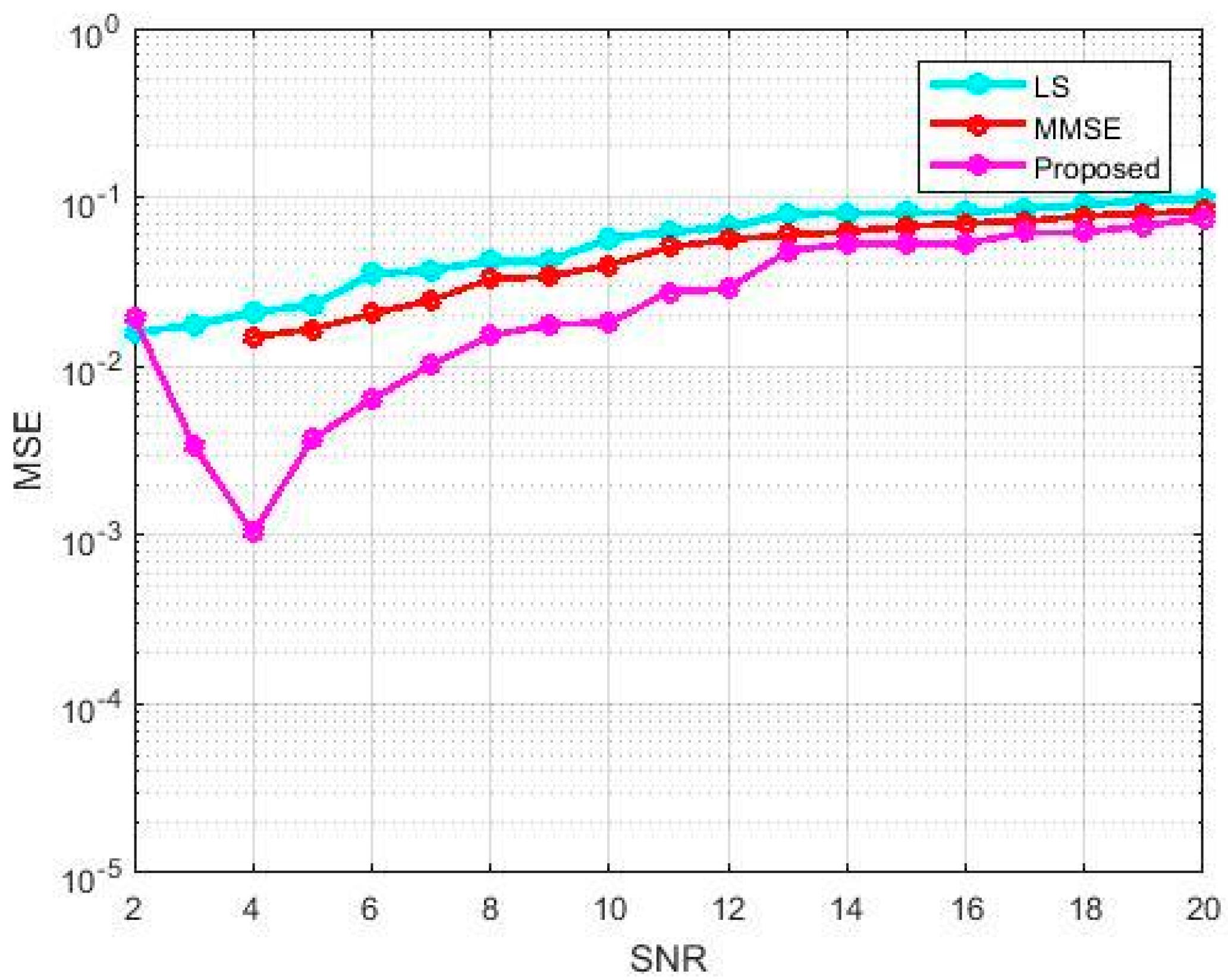
Figure 8 shows the MSE performance evaluation for the proposed system compared with the Least Square (LS) and MMSE [12]. A total of 32 subcarriers are selected through a normalized delay spread of 1/16. Sixteen QAM modulations were used with a Doppler frequency of 0.1. With QAM, the proposed system offers a SNR of above 6 dB compared to the existing LS and MMSE. Due to error transmission, the SNR goes above 20 dB. In the suggested system, 24 pilots are allocated to every source through 512 sub-carriers. The length of the CP is 8 and the symbol duration is 1.13 ms with an information ratio of 4 bits per symbol. The suggested approach was diminished with minimal computational complexity in terms of BER and MSE because the various pilots connected in our system is smaller than existing plans.
4. Discussion
In reference [12], the computational complexity of the expectation maximization (EM)-based CE depends on the data tones. The complexity is calculated for interference cancellation, coefficient calculation and their proposed method. The complexity is higher for their proposed approach due to the greater number of virtual pilots.
The computational complexity in reference [24] is very low due to the use of tensors for processing and data representation. Actually, the complexity of the CP decomposition-based method is given as . The number of paths L is too low so the complexity is modified as . The major computational task involves solving the three least squares problems at each iteration. The number of flops required to compute factor matrices for several iterations in the order of . When L is small, the dominant term has a computational complexity of order , which has a linear relationship with the size of the observed tensor Y. If the joint compressed sensing is applied along with the CP decomposition, the complexity becomes large.
Joint maximum likelihood channel and clipping amplitude estimation in reference [25] explores the potential of the receiver side compensation of the transmitter. Joint Channel and Clipping Amplitude Estimation (JCCAE) uses three algorithms for joint CE and Clipping Amplitude (CA) estimation. Since the three algorithms are iterative algorithms, the repetition of estimating the channel and CA results in high complexity.
The four Bayesian interference methods [23], such as Sparse Bayesian Learning (SBL), Gaussian Mixture Model (GMM), Pattern Coupled Spare Bayesian Learning (PCSBL) and Block Spare Bayesian Learning (BSBL), are used for multi-user detection to control the estimated signals. The calculation of posterior distribution reduces the computational complexity of the transmitted signals. However, it is not devoted to developing interference users and the e-algorithms.
The joint multi-user detection and CE methods are used in this paper with low computational complexity. Actually, many of the devices are in an active state so the user activity is low. Furthermore, there are a considerable number of zero elements in the transmitted signals due to the sparse property. This paper proposes a sparse k-NN algorithm to determine the active users and the optimal pilot patterns are selected for CE, which considers a small activity of users. The machine learning algorithm reduces the complexity to . The optimal pilot-based CE uses the CSO optimization algorithm with the smaller computational complexity of . Therefore, the overall system achieves the complexity of . The proposed algorithm not only reduces the complexity but also reduces the MAI.
5. Conclusions
This paper proposed a joint CE and MUD scheme to provide reliable and high-speed connectivity to a small number of user equipment per BS. The sparse based k-nearest neighbor (SKNN) is used to determine the unknown user activity factor. The optimum selection of pilot patterns with the help of CSO algorithm is used for the ultimate verification of sparse CE, which leads to less computational complexity. The proposed algorithm provides better performance in terms of pilot patterns with respect to BER and MSE. Thus, it avoids the interference and provides lower complexity. A spectral efficiency of the suggested CSO algorithm for CE is greater compared to the LS and MMSE methods.
Author Contributions
Conceptualization, Methodology, S.N.M., A.V.K.; Software, S.N.M.; Validation, S.N.M.; Formal Analysis, S.N.M., A.V.K.; Investigation Resources, Data Curation, Writing-Original Draft Preparation, S.N.M.; Writing-Review & Editing, Supervision, S.N.M., A.V.K.
Funding
This research received no external funding
Conflicts of Interest
The authors declare no conflict of interest.
References
- Abebe, A.T.; Kang, C.G. Overlaying machine-to-machine (M2M) traffic over human-to-human (H2H) traffic in OFDMA system: Compressive-sensing approach. In Proceedings of the 2016 International Conference on Selected Topics in Mobile & Wireless Networking (MoWNeT), Cairo, Egypt, 11–13 April 2016; pp. 1–6. [Google Scholar] [CrossRef]
- Shariatmadari, H.; Ratasuk, R.; Iraj, S.; Laya, A.; Taleb, T.; Jantti, R.; Ghosh, A. Machine-type communications: Current status and future perspectives toward 5G systems. IEEE Commun. Mag. 2015, 53, 10–17. [Google Scholar] [CrossRef]
- Bhave, P.; Fines, P. System Behavior and Improvements for M2M Devices Using an Experimental Satellite Network. In Proceedings of the IEEE Region 10 Symposium, Ahmedabad, India, 13–15 May 2015; pp. 13–16. [Google Scholar] [CrossRef]
- Ksairi, N.; Tomasin, S.; Debbah, M. A multi-service oriented multiple-access scheme for next-generation mobile networks. In Proceedings of the 2016 European Conference on Networks and Communications (EuCNC), Athens, Greece, 27–30 June 2016; pp. 355–359. [Google Scholar] [CrossRef]
- Monsees, F.; Woltering, M.; Bockelmann, C.; Dekorsy, A. Compressive Sensing Multi-user Detection for Multicarrier Systems in Sporadic Machine Type Communication. In Proceedings of the IEEE 81st Vehicular Technology Conference (VTC Spring), Glasgow, UK, 11–14 May 2015; pp. 1–5. [Google Scholar] [CrossRef]
- Beyene, Y.; Boyd, C.; Ruttik, K.; Bockelmann, C.; Tirkkonen, O.; Jäntti, R. Compressive Sensing for MTC in new LTE uplink multi-user random access channel. In Proceedings of the IEEE AFRICON 2015, Addis Ababa, Ethiopia, 14–17 September 2015; pp. 1–5. [Google Scholar] [CrossRef]
- Wang, S.; Li, Y.; Wang, J. Multiuser detection in Massive Spatial Modulation MIMO with Low-Resolution ADCs. IEEE Trans. Wirel. Commun. 2015, 14, 2156–2168. [Google Scholar] [CrossRef]
- Lu, L.; Li, G.Y.; Swindlehurst, A.L.; Ashikhmin, A.; Zhang, R. An Overview of Massive MIMO: Benefits and Challenges. IEEE J. Sel. Top. Signal Process. 2014, 8, 742–758. [Google Scholar] [CrossRef]
- Chronopoulos, S.K.; Christofilakis, V.; Tatsis, G.; Kostarakis, P. Performance of turbo coded OFDM under the presence of various noise types. Wirel. Pers. Commun. 2016, 87, 1319–1336. [Google Scholar] [CrossRef]
- Chronopoulos, S.K.; Votis, C.; Raptis, V.; Tatsis, G.; Kostarakis, P. In depth analysis of noise effects in orthogonal frequency division multiplexing systems, utilising a large number of subcarriers. AIP Conf. Proc. 2010, 1203, 967–972. [Google Scholar] [CrossRef]
- Chronopoulos, S.K.; Tatsis, G.; Kostarakis, P. Turbo Coded OFDM with Large Number of Subcarriers. J. Signal Inf. Proc. 2012, 3, 161–168. [Google Scholar] [CrossRef]
- Park, S.; Choi, J.W.; Seol, J.Y.; Shim, B. Expectation-Maximization-Based Channel Estimation for Multiuser MIMO Systems. IEEE Trans. Commun. 2017, 65, 2397–2410. [Google Scholar] [CrossRef]
- Zhou, Z.; Fang, J.; Yang, L.; Li, H.; Chen, Z.; Blum, R.S. Low-Rank Tensor Decomposition-Aided Channel Estimation for Millimeter Wave MIMO-OFDM Systems. IEEE J. Sel. Areas Commun. 2017, 35, 1524–1538. [Google Scholar] [CrossRef]
- Bao, J.; Ma, Z.; Karagiannidis, G.K.; Xiao, M.; Zhu, Z. Joint multiuser detection of Multidimensional Constellations over Fading Channels. IEEE Trans Commun. 2017, 65, 161–172. [Google Scholar] [CrossRef]
- Olfat, E.; Bengtsson, M. Joint Channel and Clipping Level Estimation for OFDM in IoT-based Networks. IEEE Trans. Signal Process. 2017, 65, 4902–4911. [Google Scholar] [CrossRef]
- Bartoli, G.; Beaulieu, N.C.; Fantacci, R.; Marabissi, D. An Effective multiuser detection Scheme for MPR Random Access networks. IEEE Trans. Commun. 2017, 65, 1119–1130. [Google Scholar] [CrossRef]
- Zhang, J.; Chen, S.; Mu, X.; Hanzo, L. Evolutionary-Algorithm-Assisted Joint Channel estimation and Turbo Multiuser Detection/Decoding for OFDM/SDMA. IEEE Trans. Veh. Technol. 2014, 63, 1204–1222. [Google Scholar] [CrossRef]
- Suikkanen, E.; Juntti, M. Study of Adaptive Detection and Channel estimation for MIMO-OFDM Systems. Wirel. Pers. Commun. Intern. J. 2017, 93, 811–831. [Google Scholar] [CrossRef]
- Choi, Y.S.; Voltz, P.J.; Cassara, F.A. On Channel estimation and detection for multicarrier signals in fast and selective Rayleigh fading channels. IEEE Trans. Commun. 2001, 49, 1375–1387. [Google Scholar] [CrossRef]
- Xie, Z.; Shor, R.T.; Rushforth, C.K. A family of suboptimum detectors for coherent multiuser communications. IEEE J. Sel. Areas Commun. 1990, 8, 683–690. [Google Scholar] [CrossRef]
- Klein, A.; Kaleh, G.K.; Baier, P.W. Zero forcing and minimum mean-square-error equalization for multiuser detection in code-division multiple-access channels. IEEE Trans. Veh. Technol. 1996, 45, 276–287. [Google Scholar] [CrossRef]
- Zhu, H.; Giannakis, G.B. Exploiting Sparse User Activity in Multiuser Detection. IEEE Trans. Commun. 2011, 59, 454–465. [Google Scholar] [CrossRef]
- Zhang, X.; Liang, Y.C.; Fang, J. Novel Bayesian Inference Algorithms for Multiuser Detection in M2M Communications. IEEE Trans. Veh. Technol. 2017, 66, 7833–7848. [Google Scholar] [CrossRef]
- Jiang, F.; Zhang, Y.; Li, C.A. New SQRD-Based Soft Interference Cancelation Scheme in Multi-User MIMO SC-FDMA System. IEEE Commun. Lett. 2017, 21, 821–824. [Google Scholar] [CrossRef]
- Nguyen, V.D.; Nguyen, H.V.; Shin, Y.; Lee, W.C.; Shin, O.S. Channel Estimation and Data Detection for Multicell Massive MIMO Systems in Correlated Channels. Wirel. Pers. Commun. 2016, 86, 1857–1877. [Google Scholar] [CrossRef]
Figure 1.
Proposed multi-user detection (MUD) and channel estimation (CE).

Figure 2.
Performance of symbol error rate (SER) vs. signal-to-noise ratio (SNR) (dB) with 20 users.
Figure 2.
Performance of symbol error rate (SER) vs. signal-to-noise ratio (SNR) (dB) with 20 users.

Figure 3.
Performance of SER vs. SNR (dB) with 100 users.

Figure 4.
Performance of bit error rate (BER) vs. signal-to-noise ratio (SNR).

Figure 5.
Performance of Uplink sum rate.

Figure 6.
Performance of Downlink sum rate.

Figure 7.
Normalized CE Error vs. number of base station (BS) antennae.

Figure 8.
Performance measure for mean square error (MSE) vs. signal-to-noise ratio (SNR).


Table 1.
Nomenclature of the system architecture of the entire paper.
| Notation | Description |
|---|---|
| NR | Number of receiver antennae |
| LA | Number of antennae |
| Input data stream | |
| Transmitting antenna | |
| a | The bit stream after the forward error correction encoder |
| Output bit stream from the interleaver I | |
| Modulated data | |
| Time domain (TD)-modulated signal | |
| n | Orthogonal frequency-division multiplexing (OFDM) symbol index |
| K | Number of subcarriers |
| Transmitted user data | |
| Cyclic prefix (CP) samples | |
| Length of the channel impulse responses | |
| Received signal for k-th subcarrier of the n-th orthogonal frequency-division multiplexing (OFDM) symbol | |
| Received signals | |
| Received pilot subcarriers | |
| Frequency-Domain Channel Transfer Functions | |
| Frequency-domain channel transfer function (FD-CHTF) coefficient of the link between the x-th user and the q-th receiver antenna in the k-th subcarrier of the n-th orthogonal frequency-division multiplexing symbol | |
| Frequency-domain additive white Gaussian noise (AWGN) | |
| K-sparse channel impulse vector | |
| q-th receiver antenna element in the k-th subcarrier of the n-th orthogonal frequency-division multiplexing symbol | |
| Mutual Coherence | |
| Overall system’s Channel Impulse Response vector | |
| Impulse vector for the K-sparse channel | |
| Subcarrier-related signals | |
| Diagonal elements | |
| Partial FFT matrix | |
| Impulse vector of K-sparse channel | |
| Subcarriers position |
Table 2.
Simulation Parameters.
| Parameters | Values |
|---|---|
| Users | 20, 100, 500 |
| No. of cell | 7 |
| No. of users per cell | 10 |
| Number of transmitters | 4 |
| Total pilots to each transmitter | 24 |
| Cell radius | 1000 m |
| Guard interval | ¼ |
| Total receivers | 4 |
| Number of Subcarriers N | 32, 128, 512 |
| Cyclic prefix | 16 |
| Signal Constellation | 16 QAM modulation |
| Path loss exponent | 4 |
| Bandwidth | 5 MHz |
| Channel | Frequency selective Rayleigh fading |
| FFT size | 2048 |
Table 3.
Complexity analysis of the proposed system.
| Operations (Per Iteration) | First Stage | Second Stage | Final Stage |
|---|---|---|---|
| Sparse k-NN algorithm | 0 | N–Np | N–Np |
| CSO optimization algorithm | Np | 0 | 0 |
| Channel estimation | 0 | 0 | O(n2) |
| Total complexity for each stage | O(n) | O(n) | O(n2) |
Table 4.
Computational complexity analysis.
| Methods | Complexity | Description of Notations |
|---|---|---|
| EM | K-frequency subcarriers, L-OFDM symbols, -pilot symbols | |
| CP | M-RF chain sub frames, T-time frames, K-subcarriers | |
| JCCAE (Joint Channel and Clipping Amplitude Estimation) | N-symbols | |
| Four Bayesian inference methods | N-received symbols, K-transmitted symbols | |
| Proposed | n-symbols |
© 2018 by the authors. Licensee MDPI, Basel, Switzerland. This article is an open access article distributed under the terms and conditions of the Creative Commons Attribution (CC BY) license (http://creativecommons.org/licenses/by/4.0/).
Share and Cite
MDPI and ACS Style
Motade, S.N.; Kulkarni, A.V. Channel Estimation and Data Detection Using Machine Learning for MIMO 5G Communication Systems in Fading Channel. Technologies 2018, 6, 72. https://doi.org/10.3390/technologies6030072
AMA Style
Motade SN, Kulkarni AV. Channel Estimation and Data Detection Using Machine Learning for MIMO 5G Communication Systems in Fading Channel. Technologies. 2018; 6(3):72. https://doi.org/10.3390/technologies6030072
Chicago/Turabian StyleMotade, Sumitra N., and Anju V. Kulkarni. 2018. "Channel Estimation and Data Detection Using Machine Learning for MIMO 5G Communication Systems in Fading Channel" Technologies 6, no. 3: 72. https://doi.org/10.3390/technologies6030072
Note that from the first issue of 2016, this journal uses article numbers instead of page numbers. See further details here.