1. Introduction
Diabetes mellitus is one of the most common diseases across the globe, and one of the major causes of death and disabilities for hundreds of millions of people [
1,
2,
3]. Electrochemical sensors based on amperometric measurements are the most common devices for glucose detection. However, the specificity and the purity of the detected signals are still a challenge, due to several distributions, such as the effects of the substrates of the working electrode and the applied voltages during the oxidation and reduction process [
4,
5]. The ability to monitor glucose accurately and regularly requires highly sensitive, highly selective, and reusable glucose sensors. [
6,
7,
8,
9,
10]. A ZnO NR-based glucose sensor was tested by Wei et al. Although ZnO NRs were grown on a thin gold film, the influence of gold was not investigated and the device was tested under 0.8 V. The obtained sensitivity was in the order of 23.1 µA·cm
−2·mM
−1, and it was not filtered by subtracting the influences of the substrate [
11]. A glucose sensor, based on ZnO NRs, was investigated by Liu et al. ZnO NRs were grown on a conductive indium tin oxide (ITO) and immobilized with glucose oxidase (GO
x). The obtained sensitivity was considered to be the net sensitivity, without subtracting the effects of ITO [
12]. The growth of ZnO NRs on different substrates was investigated by Nozaki et al. Galuim nitride (GaN) was chosen as the best substrate to fabricate a glucose sensor and the fabricated device was tested under different glucose concentrations. The influence that GaN has on the device performance was not taken into consideration [
13]. Recently, Rafiq Ahmad et al. fabricated an integrated field effect transistor-based biosensor and they obtained a high output drain current after the applied-biased gate voltage reached a high value. [
14]. The effects of surface morphologies were investigated by Jing et al. and a glucose sensor was fabricated out of the synthesized ZnO nanorods. The influence of the substrate and the oxidation-reduction potential were not covered, and the sensor exhibited sensitivity in the order of 2.08 µA·mM
−1·cm
−2 [
15]. A non-enzymatic ZnO NR-based sensor was fabricated and characterized by Saranqi et al. The focus was on the effects of the enzyme and the use of the ultraviolet UV-light on the performance of the sensor [
16]. An enzymatic glucose sensor, based on AlGaN/GaN and ZnO nanorods, was studied by Lee and Chiu. A photoelectrochemical passivation method was used to cover the synthesized ZnO nanorods from both sides, and the device showed a sensitivity of ~38.9 µA/mM, with a range in the glucose concentration of 800 nM–25 mM [
17].
In this work, we report on the fabrication and characterization of an electrochemical glucose sensor, based on Si/SiO2/Au/ZnO NRs/GOx/Nafion, that can be used for the in vitro monitoring of glucose. Cost effective, environmentally friendly, and accurate hydrothermal and sol-gel techniques, were utilized in low temperatures, in order to grow ZnO NRs. An electrochemical glucose sensor from the as-grown ZnO NRs was fabricated, characterized, optimized, and tested, under room temperature. Safe, biocompatible, and non-toxic equipment and tools were used for characterization. In this study, more attention was spent on investigating the influence of the substrate and the applied potentials, which have not been scrutinized in detail, in previously reported articles.
2. Experimental Methods
2.1. Materials
Zinc acetate dehydrate 99%, zinc nitride hexahydrate Zn(No3)2·6H2O, and methoxyethanol 99% were purchased from Sigma Aldrich Company (St. Louis, MO, USA), with no more purifications. Ethanolamine HOCH2CH2NH2 99% and hexamethylenetetramine were bought from Alfa Aesar Company (Ward Hill, MA, USA), and stored in the glove box under nitrogen. D-Glucose (DEXTROSE) ANHYDROUS C6H12N6 was purchased from amResco Company (Solon, ON, USA). Si wafers with a 100 nm oxide layer were purchased from Wafer Company (Boston, MA, USA).
2.2. Preparation of the Substrate
Si/SiO2 wafers were diced into 0.5 × 0.5 cm2 specimens, and cleaned chemically and carefully in an ultrasonic path. The samples were dipped in trichloroethane and sonicated for 10 min, after which they were cleaned by DI water and dipped in an ethanol, before being sonicated for another 10 min. The same cleaning process was carried out to clean the samples using acetone and DI water. Following this, a spin coating cleaning technique was utilized. The samples were placed in a substrate and located in the spin coater, and an acetone-methanol-acetone cleaning process was performed for 15 s with acetone, 15 s with methanol, and for a further 15 s with acetone. The sample was dried with nitrogen while spinning for 15 s. A thin gold film with a 100 nm thickness was deposited using an e-beam evaporator with a deposition rate of 10 Å/s. The deposition was performed under vacuum, with a pressure of ~10−7 Torr.
2.3. Zinc Oxide Nrs Growth Procedure
A low-temperature hydrothermal growth method and sol-gel solution were adopted to directly synthesize ZnO NRs on Si/SiO2/Au. The synthesis procedure consists of two major steps: preparation of the seed layer (sol-gel) and preparation of the growth solution. Zinc acetate dehydrate with a concentration of 0.5 M, which is equal to 1.1 gm, was dissolved in 10 mL of methoxyethanol 99%, and the solution was stirred for 1 h. Following this, 0.25 M of ethanolamine +99% was added to the solution to assure a complete dissolving of the zinc acetate in the methoxyethanol 99%. After an hour, the solution was placed in an ultrasonic path for 15 min, and filtered and stored at room temperature. The growth solution was performed by dissolving 0.05 M of zinc nitride hexahydrate Zn(No3)2·6H2O in 10 mL of deionized water, and 0.05 M of hexamethylenetetramine (CH2)6N4 in 10 mL of deionized water. Both solutions were placed on a magnetic stirrer for 1 h, and then hexamethylenetetramine was added drop-by-drop to zinc nitride hexahydrate, while stirring. The two mixed solutions were left for further purification. An ultrasonic path was used to further prepare the growth solution and finally, a small filter was used to prevent any undissolved particles from remaining in the solution.
Three layers of the prepared sol-gel were spun coated on top of the cleaned and prepared Si/SiO2/Au samples, at 3000 rotations per minute (rpm). A one hour annealing procedure was performed for the seed layers at 110 °C, and the annealed samples were pasted onto a glass slide and immersed upside down in the growth solution in a 20 mL screw glass vial, before being placed in a furnace. The growth time and temperature were chosen to be 4 h and 85 °C, respectively, and then the samples were cooled naturally and rinsed with deionized water three times to stop any further growth of ZnO NRs. Finally, they were dried at 300 °C for 15 min.
2.4. Working Electrode Surface Modification
After a successful growth of ZnO NRs using the method described above, the surface of the as-grown ZnO Nrs was modified as follows:
- (A)
The prepared structure was placed in phosphate buffer solution (PBS) with a pH level of 7.4, and left in the air to increase the absorbance of the surface of the electrode by generating a hydrophilic surface [
18].
- (B)
Different concentrations of the enzyme glucose oxidase (GO
x) were performed and used to immobilize the working electrode. Details regarding the optimization of the enzyme can be found in the results and discussion section. A 40 mg/unit of the enzyme glucose oxidase was utilized to immobilize the surface of the working electrode with GO
x. Glucose oxidase with a concentration of 40 mg/mL was dissolved in 0.01 M of PBS, and 1 µL of the prepared GO
x was dropped on top of the Si/SiO
2/Au/ZnO NRs using a micropipette, before being left at 4 °C for 6 h [
19].
- (C)
The non-adsorbed GOx by ZnO NRs was removed from the surface of the working electrode, using a covalent method with a higher ionic solution. A phosphate buffer solution with pH level of 7.0 and 4.4 M that provides 80 mM of ionic strength, is used to remove the excess of the non-adsorbed GOx. The working electrode was rinsed in the prepared solution five times, for 20 s each time. Removing the non-adsorbed GOx helps to increase the stability of the enzyme and increases the lifetime of the electrode from days, to months.
- (D)
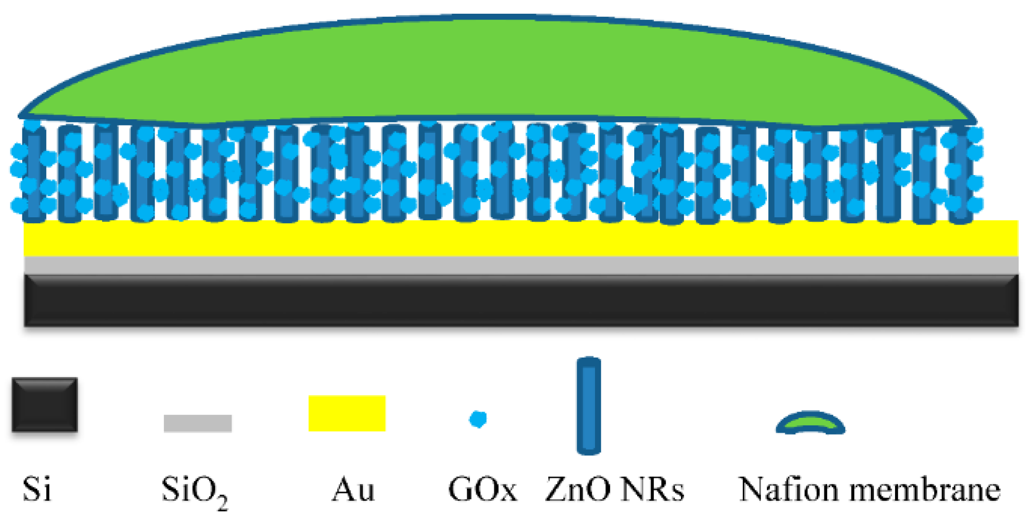
The last modification step of the working electrode was completed by covering the surface of the electrode with a nafion membrane. A 1 µL drop of the nafion solution was deposited on the working electrode’s surface, and the electrode was left to dry for 2 h at 4 °C. A schematic structure of the working electrode can be seen in
Figure 1.
2.5. Material and Device Characterizations
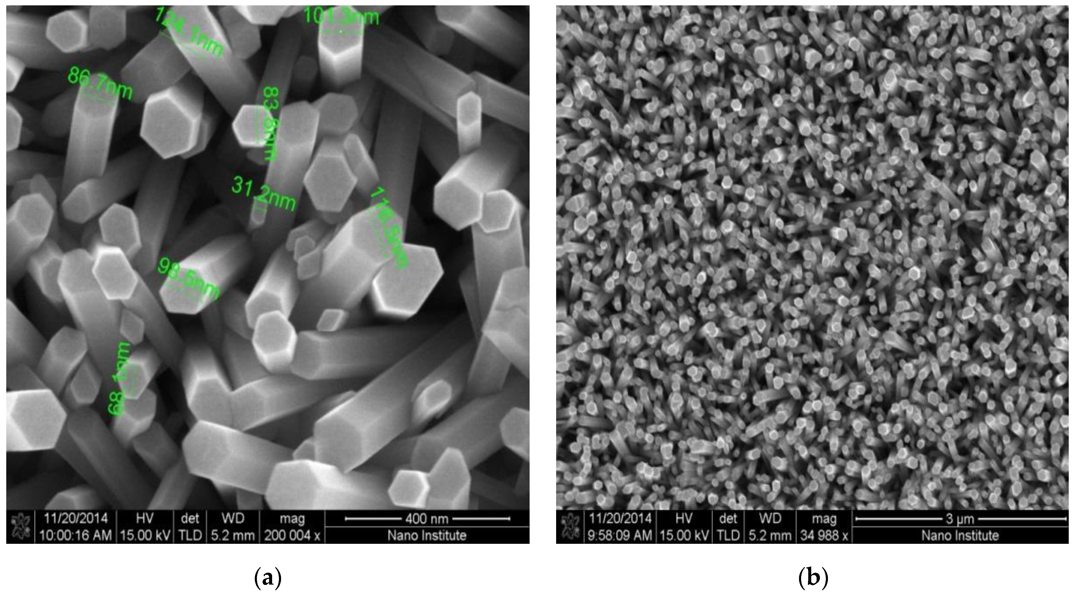
The high density and good alignment of the as-grown ZnO NRs can be seen in
Figure 2a,b.
Figure 2a shows an SEM image of the as-grown ZnO NRs with a 400 nm focusing area and 200,004 × magnification. From the image, one can see both the uniform distribution of the diameters of the nanorodes, and the three dimensional active area that hosts the electrochemical reaction. The focus area of the SEM image in
Figure 2b has a dimension of 3 µm, with a magnification of 34988 ×. A uniform distribution of the seed layer at 3000 rpm resulted in a well aligned and high density set of nanorods in the surface of the working electrode, with a small variation in their diameter. This was a direct consequence of the high active electrochemical reaction area and consequently, the high output current. In addition, ZnO NRs provide a free path of electrons between the glucose and the surface of the electrode, and a high surface-to-bulk ratio. Glucose oxidase can be adsorbed in a large surface area that is provided by the high surface-to-volume ratio of the as-grown ZnO NRs [
20].
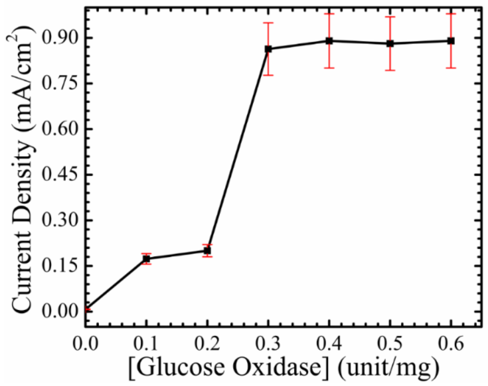
For device characterization, all measurements were performed using a Source Meter Keithley 2410 and an electrochemical impedance analyzer (Gamry potentiostat, Gamry Instruments, Warminster, PA, USA), and the measurements were performed in a PBS with a pH of 7.4. The surface of the fabricated electrode was immobilized with glucose oxidase (GO
x) as an enzyme mediator, and a nafion membrane for enhancing device stability and increasing ion exchange. An optimization procedure was performed to optimize the amount of GO
x needed for working electrode surface immobilization. The working electrode was modified with four different concentrations of GO
x, 10, 20, 30, and 40 mg/unit, and the highest current density was observed at 40 mg/unit. This is evidence that the coupling between ZnO NRs and GOx helps in different ways. For instance, ZnO NRs help in creating a nano-incubative environment for GOx, so more enzyme can be adsorbed in the nano-sensable reactive area [
21]. Furthermore, ZnO NRs create multi-tunnels, so electrons can be easily transferred from the surface of the ZnO NRs, to the surface of the electrode [
22]. On the other side, GOx provides a suitable nano-environment for the glucose to react with the oxygen, and to produce hydrogen peroxide (H
2O
2) on the surface of the working electrode [
23,
24]. The optimization procedure can be seen in
Figure 3, and 40 mg/unit of GO
x is used, in order to immobilize the working electrode for further investigations.
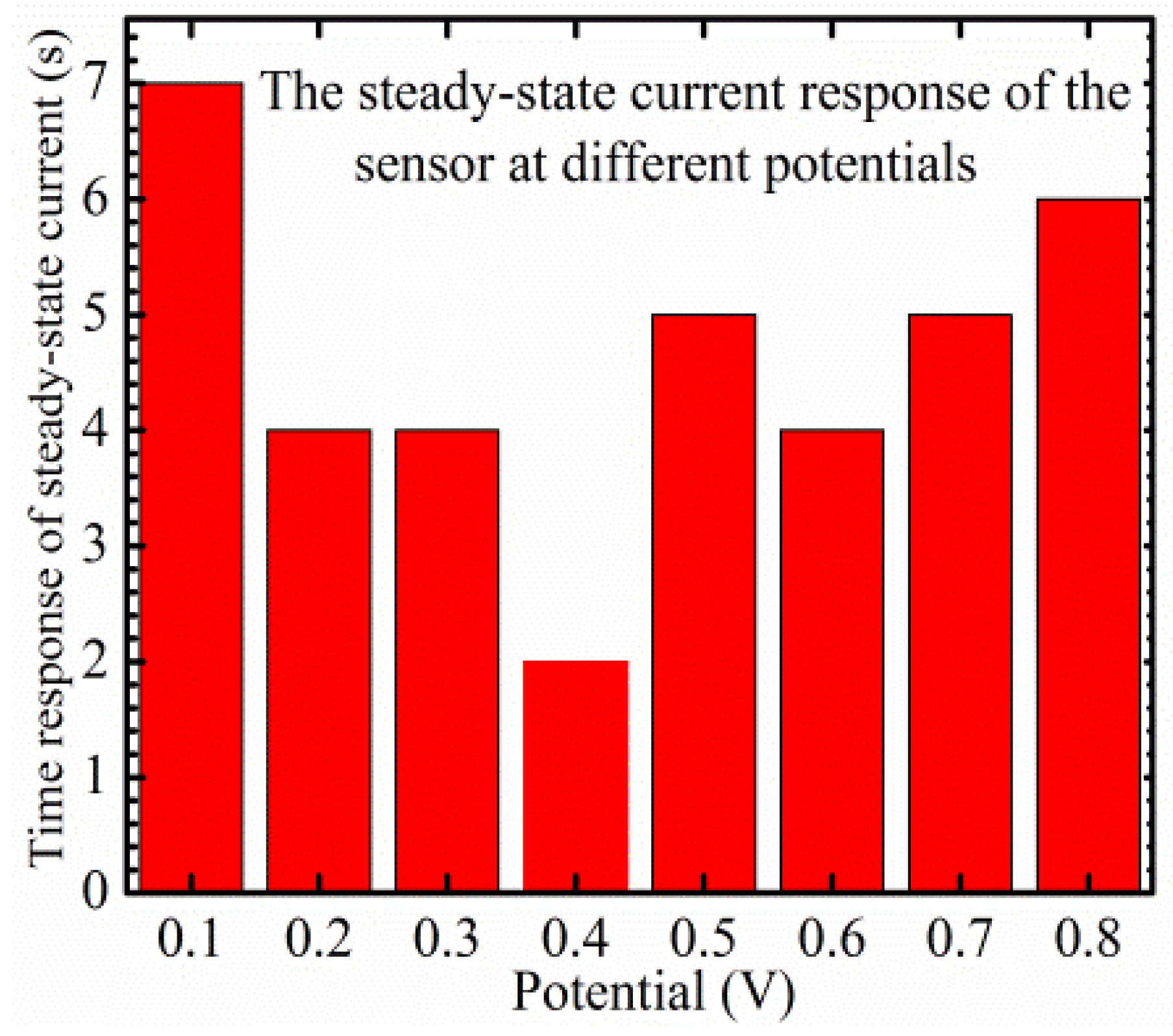
A platinum plate was used as a counter electrode and the device was tested in a range of voltages, 0.1–0.8 V. To optimize the applied potential, a steady-state current study is performed, in order to test the sensor’s response time changes in glucose concentrations. A range of applied potentials, 0.1–0.8 V, was utilized in the optimization study. The fastest and sharpest response was observed at 0.4 V, and the steady-state current and the saturation level were reached within 2 s with different glucose concentrations. The optimization condition is presented in
Figure 4.
Additionally, the effects of the substrate were studied by testing the structure Si/SiO2/Au/GOx/nafion (baseline in this paper), without the growth of ZnO NRs. Following the growth of ZnO NRs on Si/SiO2/Au/GOx, and after immobilizing the working electrode with GOx and the nafion membrane, the measured current densities, as a function of glucose concentrations of the fabricated device, were subtracted from the obtained current densities of the baseline. Both the current densities for the device and the baseline were sensed under 0.4 V. The same procedure was completed with the obtained lower limit of detection.
The electrochemical sensor works because of the oxidation of hydrogen peroxide (H
2O
2) and the reduction of oxygen in the presence of the enzyme GO
x, and the chemical reaction can be described as follows [
25,
26,
27]:
Glucose oxidase helps in enhancing the specificity of the sensor by allowing only glucose to react with the oxygen. A nafion membrane is necessary for enhancing the exchange of ions between H2O2 and the surface of the working electrode (ZnO NRs), and for increasing the stability of the working electrode. The glucose reacts with oxygen and produces H2O2, and this H2O2 gives H2, O2, and free electrons to the surface of the working electrode. Under the applied potentials, the generated electrons move in order to compensate for the lack of electrons in the oxygen molecules, since oxygen is reduced in the surface of the counter electrode. Those electrons can be collected as an output current that is proportional to the glucose concentrations in the analyzed medium. The importance of ZnO NRs in this electrochemical reaction is very clear since the reaction takes place on the surface of the immobilized electrode. The electrochemical reaction area can be calculated as follows: [Nanorods’ area ×density of nanorods x substrate’s area] and this can be written as [2πrh () × substrate’s area], where h and r are the length and radios of ZnO NRs, respectively. Increasing the density of the nanorodes leads to an increase in the active area, and as it can be seen, the nanostructure of the working electrode helps in increasing the reaction area several times more than the bulk structure. In other words, the as-grown ZnO NRs have three dimensional areas, while bulk materials only have two dimensional areas. In addition, there is a high affinity between ZnO NRs and GOx, since the as-grown ZnO NRs have a high isoelectric point of around 9.5, with a positively charged surface, whereas the enzyme GOx only has a 4.2 isoelectric point, with a negatively charged surface. A higher amount of the immobilizing enzyme can be effectively adsorbed into the three dimensional nanostructured areas, allowing more glucose to react with oxygen on the surface of the working electrode. This is one of the reasons which can be used to explain the ability of the fabricated electrochemical sensor to detect a wide range of glucose concentrations.
The effects of the (baseline) Si/SiO
2/Au/GO
x/Nafion on sensitivity, LOD, and time response, were studied under a range of applied potentials, 0.1–0.8 V, and with glucose concentrations ranging from 1–10 mM. In addition, the sensitivity, LOD, and time response of the Si/SiO
2/Au/ZnO NRs/GO
x/Nafion (device), were calculated in the same rage of voltages and same range of glucose concentrations. The energy that is required to force the charges to transfer from the working electrode to the counter electrode, is known as the applied potential. At the interface surface between the electrode and the electrolyte, there is an equilibrium potential, and thus no electrochemical reaction accrues. Once an external potential is applied, the hydrothermal equilibrium breaks, and an electrical current starts to flow, due to the oxidation reaction at the surface of the immobilized working electrode, and a reduction process at the surface of the counter electrode [
28]. In glucose electrochemical sensors, the specificity must be taken into consideration to increase the purity of the detected signal, and to prevent other electroactive species in the tested medium from being oxidized.
3. Results and Discussion
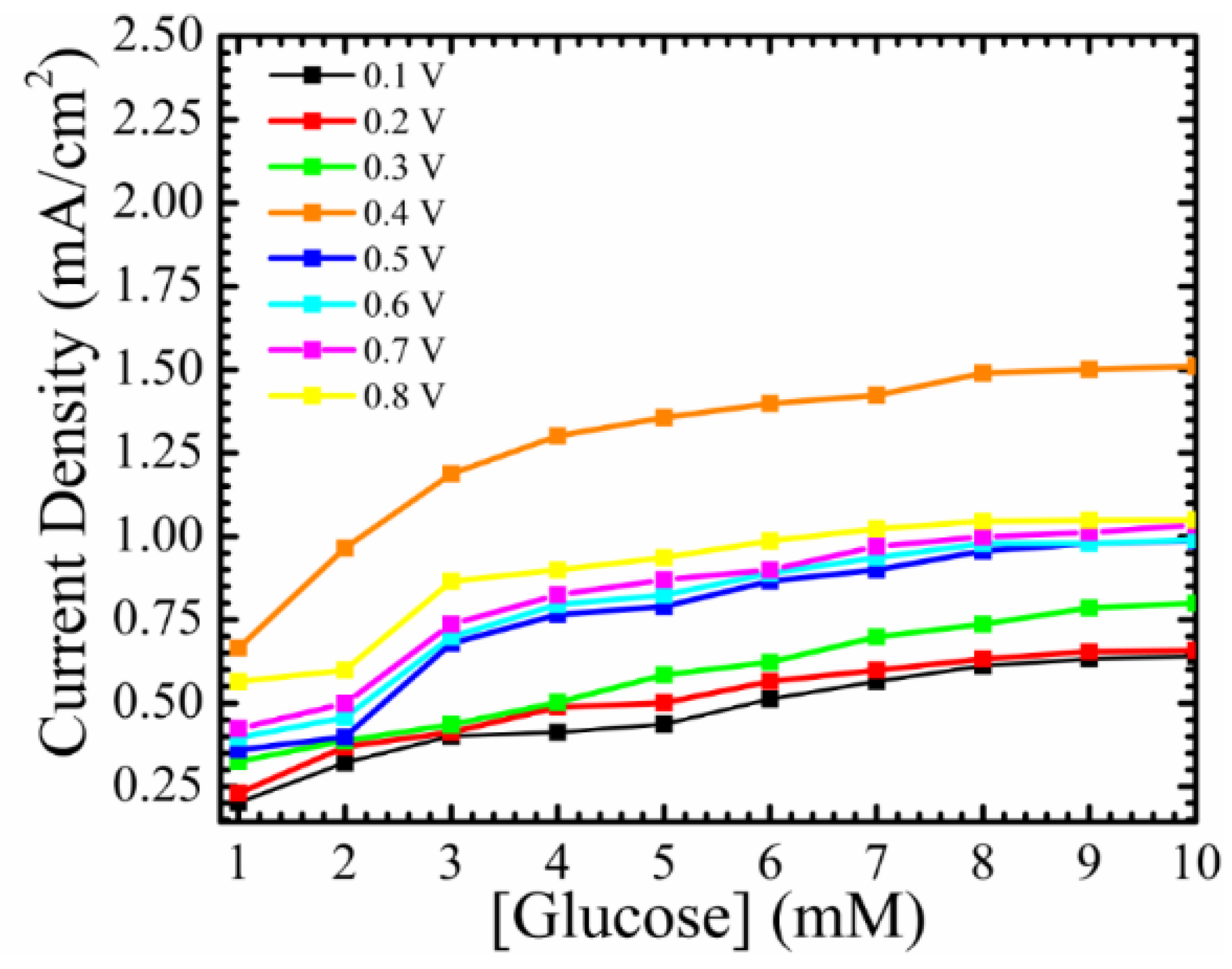
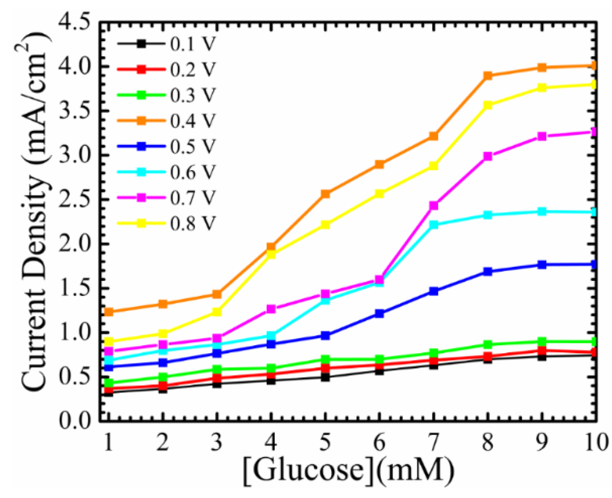
Figure 5 shows the current density as a function of glucose concentrations of different oxidation voltages of the (device) Si/SiO
2/Au/ZnO NRs/GO
x/Nafion. It shows the influence of ZnO NRs on the sensing area of the working electrode. The sensitivities were calculated to be the slope of the linear line, and the LOD can be calculated from 3 × δ/slop, where δ is the standard deviation of the intercept. As it can be noted from the figure, the fabricated working electrode showed a steady-state current with different glucose concentrations under different applied potentials, and it was saturated when the glucose concentrations reached 8 mM. This is because of the higher affinity between the surface of the as-grown ZnO NRs and the enzyme. The nanostructured surface provided a three dimensional-nonstructural hosting area, in which more GO
x could be adsorbed. In addition, the as-grown ZnO NRs provided a free path to transfer electrons. The device showed a higher sensitivity at 0.4 V ~0.468 mA/cm
2 mM with a detection limit of ~166.6 µM, with a maximum current density detected at ~4 mA/cm
2. The fabricated device exhibited a linear line of changes in current densities, with the addition of more glucose to the PBS, from 3–8 mM. This increases the capability of the fabricated electrochemical sensor to be with the devices that are used in real-time glucose detection.
Figure 6 represents the current density of the baseline under the same conditions. The working electrode is characterized without ZnO NRs grown on top of it, so the sensible area has two dimensions, instead of three dimensions. It is the reason behind the lower observed sensitivity. The maximum value of the steady-state current density was ~1.5 mA/cm
2, and comparing that with the maximum steady-state current density of ~4 mA/cm
2 after the growth of ZnO NRs on the surface of the working electrode, gives a clear picture regarding the enhancement accrued to the detected signal. Not only the steady-state current density was enhanced, but also the fabricated electrochemical sensor showed a linearity behavior with higher glucose concentrations. The fabricated working electrode showed a saturation in the current density after the glucose concentrations passed the physiological-clinical levels for diabetes detections. Without the growth of ZnO NRs, the baseline showed a linear line from ~(1–4) mM, which means that the working electrode is out of the range for any clinical usage of glucose monitoring. The sensitivity of the baseline at 0.4 V was calculated to be 0.085 mA/cm
2 mM, with a detection limit of ~384 µM. The net sensitivity of the fabricated electrochemical sensor at a 0.4 applied potential is 0.468 − 0.085 = 0.303 mA/cm
2 mM, and it emphasizes the influence that the as-grown ZnO NRs have on such devices. Since the surface of the working electrode without ZnO NRs has a lower surface-to-bulk ratio, less GO
x can be adsorbed, and this is why the sensor was saturated in lower concentrations of glucose. The baseline has an impact on the ultimate performance of the fabricated electrochemical sensor tested at different potentials. The influence of the baseline should be taken into consideration during the process of designing electrochemical sensors, and the net performance of the fabricated sensor in terms of sensitivity, LOD, and time response, is a crucial point to consider in terms of applying such sensors in real-time glucose monitoring.
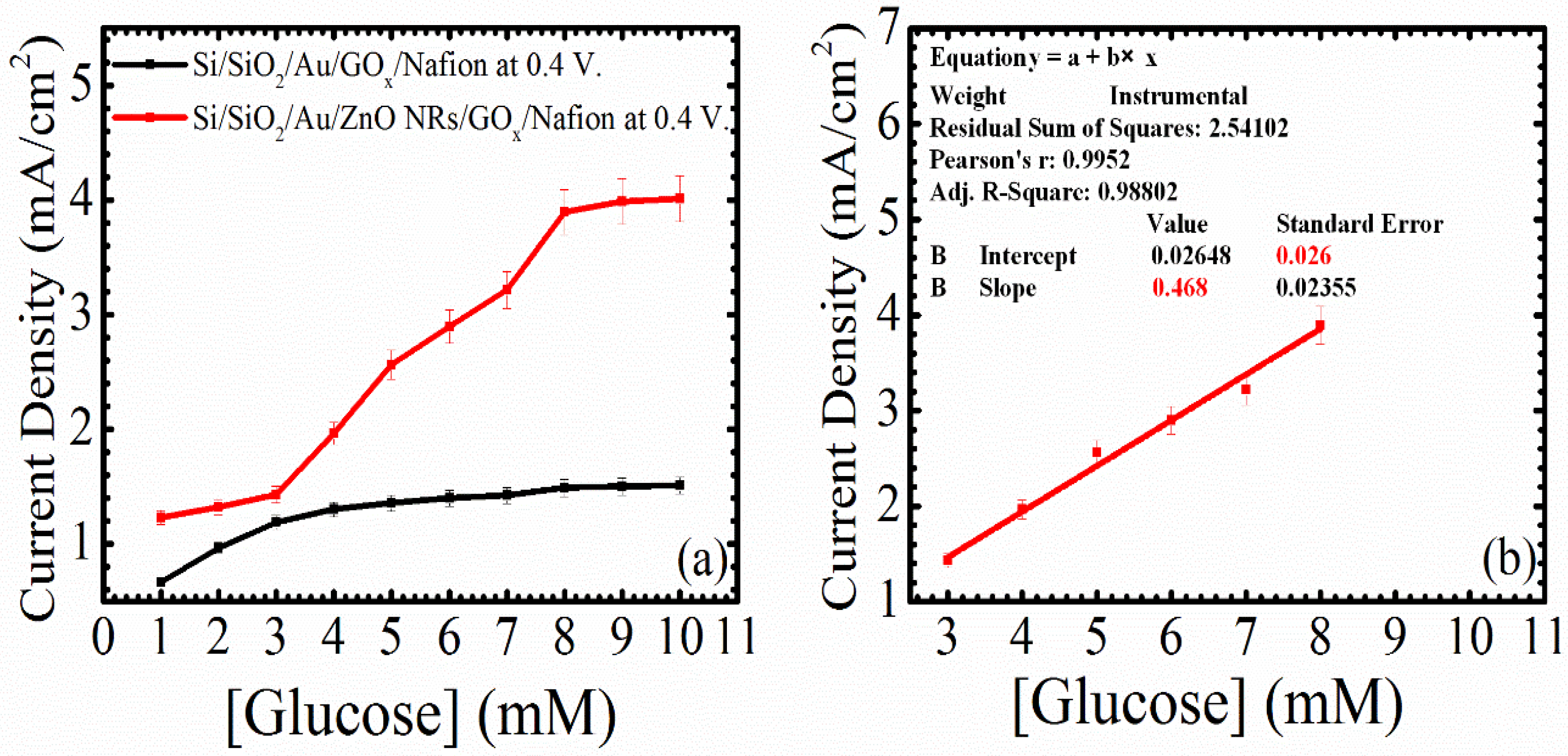
Figure 7a is the current density of the device and the baseline as a function of the glucose concentrations at 0.4 V. The fabricated working electrode showed constant changes in the current density when adding or changing glucose concentrations. After the applied potential passes the equilibrium potential between the working and the counter electrodes, H
2O
2 is produced as an electrochemical reaction product, and it is oxidized on the surface of the as-grown ZnO NRs, as shown in Equation (2). In
Figure 7a, one can see slight changes in the current density, with increasing glucose concentrations on the surface of the working electrode without the growth of ZnO NRs. After the growth of ZnO NRs on the surface of the working electrode, the fabricated sensor exhibited clear changes in current density with the addition of glucose to the PBS. In addition, the glucose active range was extended from 3–8 mM, and this can be found in
Figure 7b.
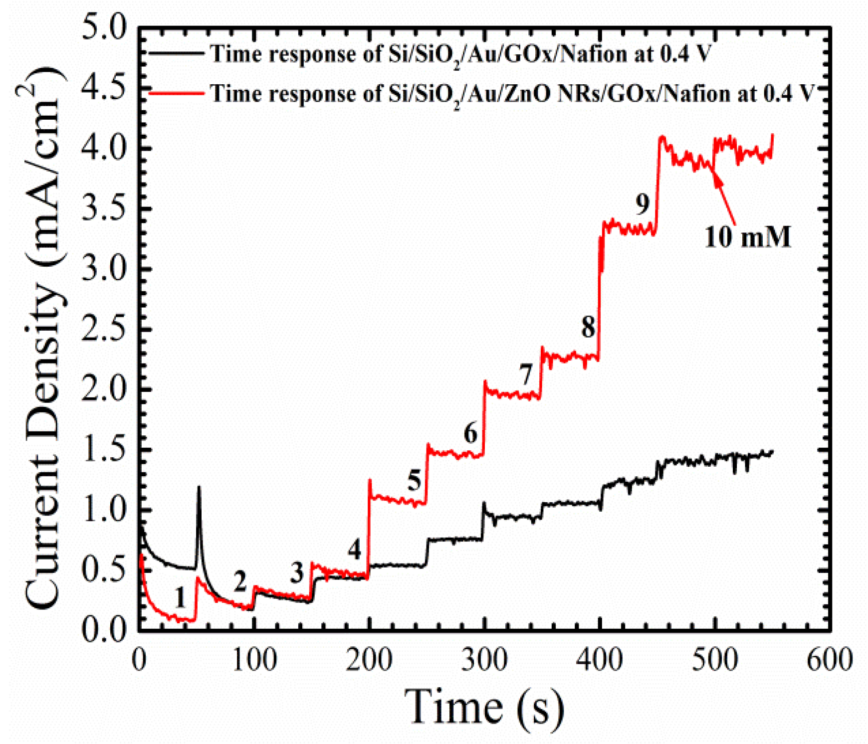
The time response of the electrochemical sensor with and without the growth of ZnO NRs tested at 0.4 V for different glucose concentrations from 1–10 mM, is shown in
Figure 8. Glucose concentrations were continuously increased by adding 1 mM of glucose to the PBS every 50 s, with a continuous stirring to give the glucose enough time to dissolve in the solution. The fabricated Si/SiO
2/Au/ZnO NRs/GO
x/Nafion (device) showed a fast and sharp step changes response of ~2 s, with a much lower level of noise than the baseline, especially in high glucose concentrations. Furthermore, the average increase in the current density with each new concentration of glucose was around 0.45 mA/cm
2 for the working electrode with ZnO NRs, whereas the baseline showed an average increase in the current density of ~0.1 mA/cm
2 with the same glucose concentrations. The fast response and the low noise behaviors of the device are direct results of the free path of electrons from the surface of the as-grown ZnO NRs, to the gold surface. Also, those results are associated with a high surface-to-volume ratio, created by the as-grown ZnO NRs on the surface of the electrode, which could accelerate the oxidation-reduction reaction.
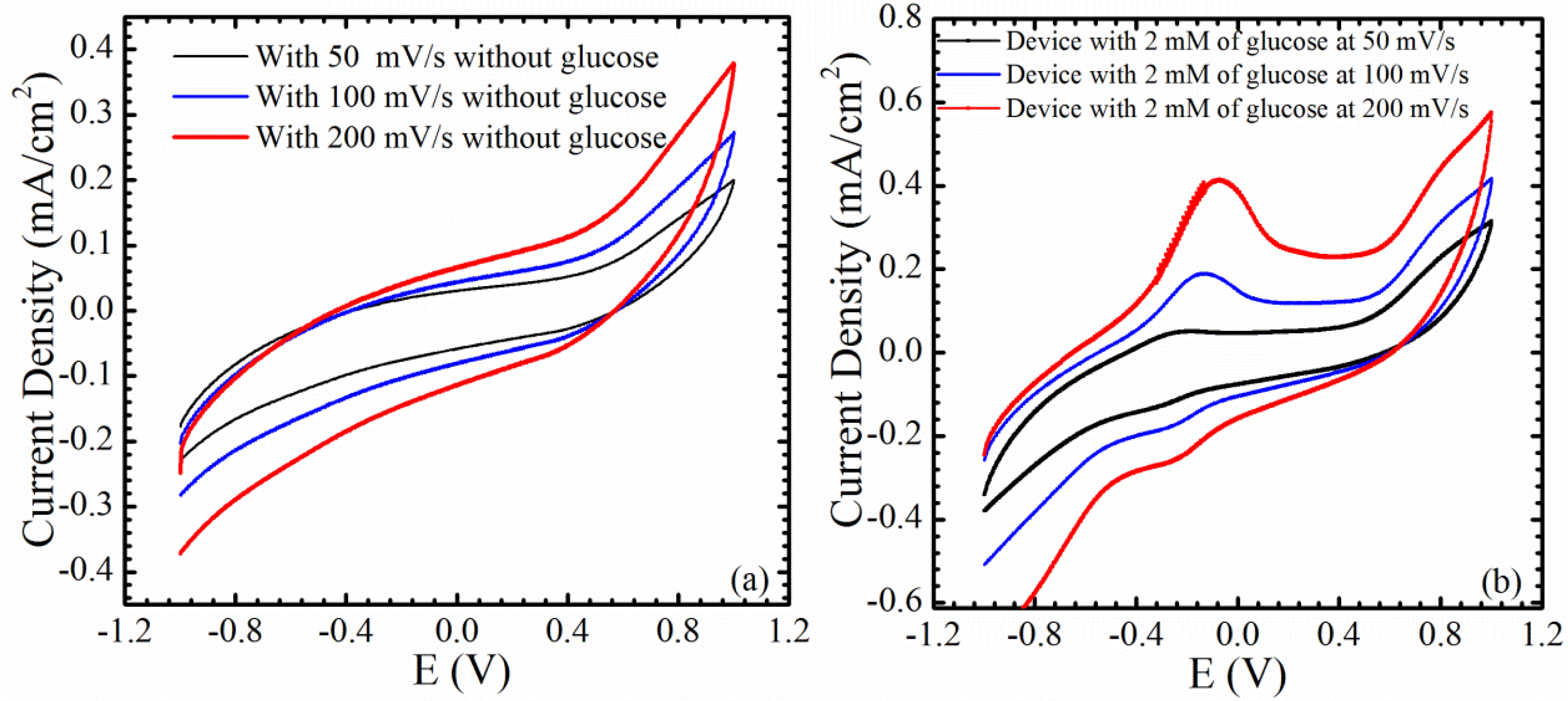
Cyclic voltammetry measurements were performed using a Gamry potentiostat to analyze the oxidation and reduction reaction between the working and counter electrodes, with and without glucose, and this can be found in
Figure 9a,b. The tests were conducted at different scanning rates, 50, 100, and 200 mV/s, and from −1 to 1 V. The oxidation anodic peak and the reduction cathodic peak were not clear in the absence of glucose in the PB solution, indicating that the device has a good chemical stability, as can be seen in
Figure 9a. Coating the working electrode with a nafion membrane helps to create a stable electrochemical sensor that is sensitive only to changes in glucose in the electrochemical microenvironment.
Figure 9b shows the cyclic voltammogram graph after an addition of 2 mM of glucose, with a sweep voltage from −1 to 1 V. The anodic oxidation peak and the cathodic reduction peak are proportional to the scan rate, as can be seen from the figure. The reason behind the appearance of both peaks in the negative part of the scan, is that the electrochemical oxidation of hydrogen peroxide could be revisable. In other words, H
2O
2 can be oxidized to H
2, O
2, and a free electron, and H
2 and O
2 can be reduced again to H
2O
2, in the reverse direction. In this case, the oxidation of H
2O
2 can be stronger than the reduction of O
2, and the reaction can be called a foreword reaction, or vice versa.
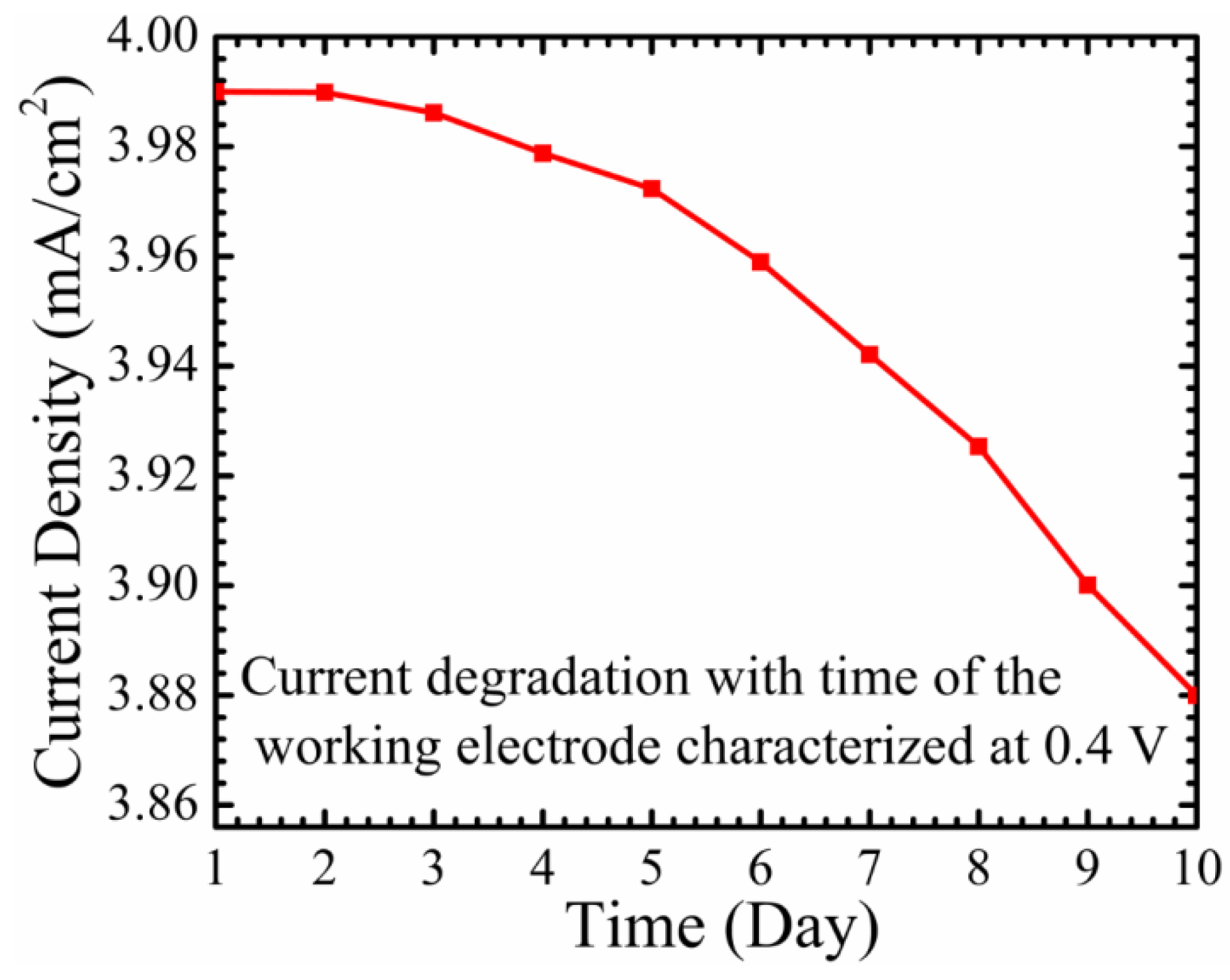
Figure 10 represents the stability and the reproducibility of the working electrode, characterized at 0.4 V. It can be ascertained that the degradation of the sensed current is around 11% after ten days. The maximum current density achieved at day one was 3.99 mA/cm
2, and the working electrode exhibited a current density of around 3.86 mA/cm
2 at day 10. This can be considered as demonstrating the high stability of the working electrode, and is a positive indicator of the effectiveness of using a covalent immobilizing method with a higher ionic solution. Nevertheless, the immobilized working electrode with the enzyme GO
x should still be stored in a fridge at 4 °C, after each use. In fact, this triggers the need for a non-enzymatic glucose sensor to eliminate the reproducibility problem, and to increase the stability and the lifetime of the sensor.
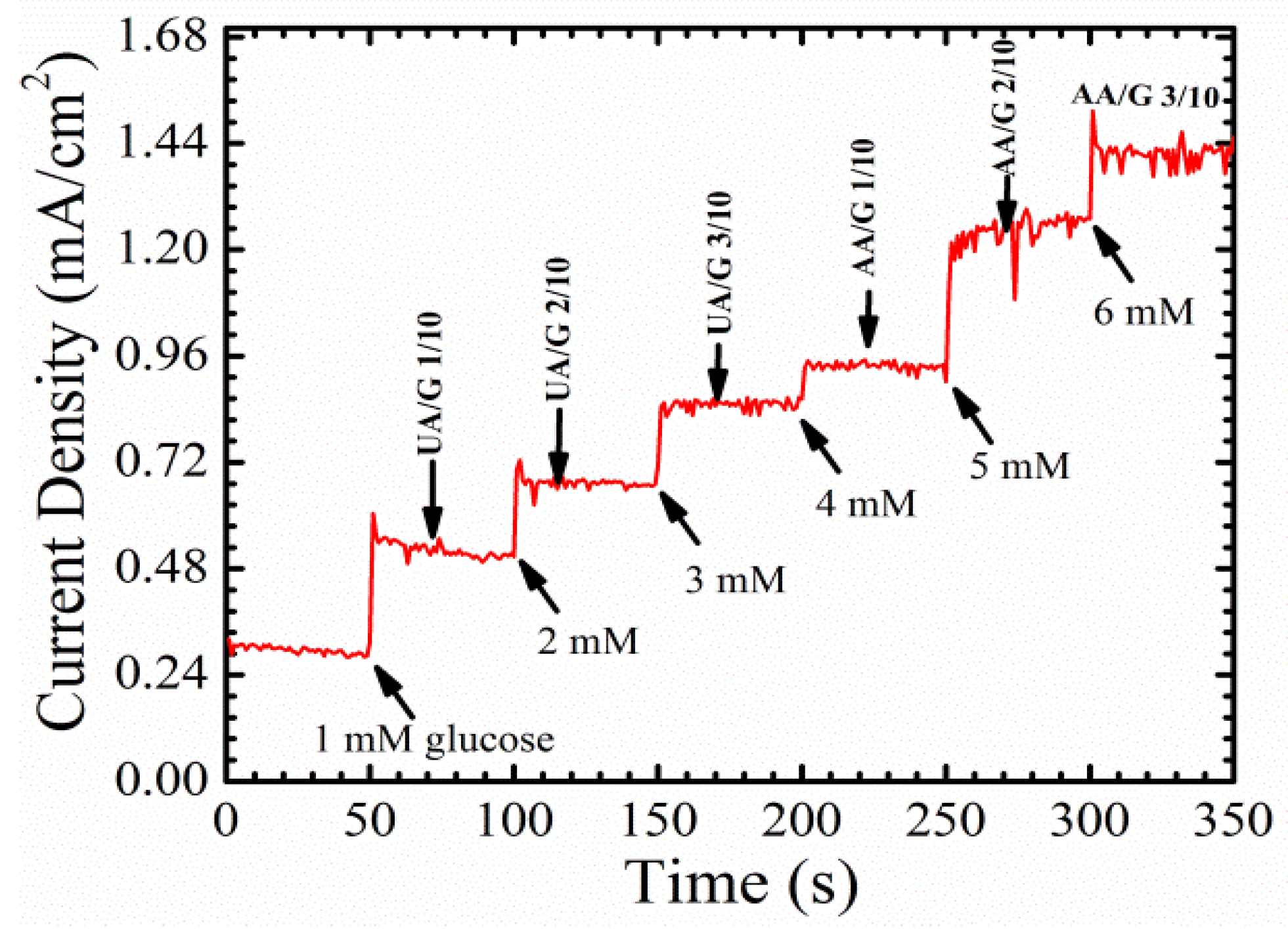
To examine the specificity and selectivity of the fabricated enzymatic glucose sensor, uric acid and ascorbic acid, which are the main electroactive species in the blood, were used alongside glucose.
Figure 11 shows the amperometric response of the sensor with different electroactive species. The amount of glucose in the blood is around 30–50 times higher than the concentrations of both uric and ascorbic acid [
6,
29]. Nevertheless, three different ratios of uric acid/glucose, 1/10, 2/10, 3/10, and three different ratios of ascorbic acid/glucose, 1/10, 2/10, and 3/10, were prepared, in order to investigate and prove the selectivity of the sensor. It seems that ascorbic acid at higher concentrations, (AA/G) 2/10 and (AA/G) 3/10, has a slight influence on the performance of the device. This could be because of the leakage in the nafion membrane, which caused a distortion in the detected signal.
The advantages of the fabricated electrochemical sensor, when compared to other published sensors, are summarized in
Table 1.


