1. Introduction
The presence of mechanical stimuli has been shown to instigate cell differentiation [
1,
2,
3,
4,
5,
6]. It can also be used to prevent de-differentiation of cells [
7]. However, inappropriately applied stimulus may cause cells to differentiate towards an undesirable lineage and even cell apoptosis resulting in tissue degeneration [
8]. De and Safran [
9] have previously shown that, in a cell-scaffold construct, the resulting stiffness of the matrix is a function of cellular response to the external mechanical stimulus at a particular frequency.
In the body, the intervertebral disc is an organ that is regularly exposed to mechanical stresses. While back pain due to intervertebral disc degeneration is a common problem, little is understood about the cells that make up the nucleus pulposus, the gel-like component of the disc. As the disc degenerates, the nucleus pulposus becomes less gelatinous, leading to cracks and fissures [
10]. Previous research has shown that fluid flow [
11,
12,
13], hydrostatic pressure [
14], and compressive stresses [
8,
15,
16,
17] contribute to the mechanical changes in the disc.
However, there have been limited studies published on the use of bioreactors being employed in the field of disc tissue engineering [
18]. In attempting to tissue engineer the intervertebral disc, the current bioreactor designs were found to be lacking, being capable of only one or two types of stimulus. These bioreactors do not accurately reflect physiological conditions. This study aimed at the development of a bioreactor that could mimic the
in vivo conditions experienced by the human vertebral disc: compression, hydrostatic pressure and pulsatile fluid flow forces.
2. Design of the Multiaxial Bioreactor
A triaxial bioreactor was developed that closely mimics the in vivo conditions experienced by the intervertebral disc. To enable investigation of biological variation within the cell-scaffold constructs, the system was designed to accommodate up to four samples simultaneously in separate sample mounts which allow perfusion of media through the scaffolds. Different combinations of compressive stresses and pulsatile flow can be dynamically and concurrently administered to the samples. The system is controlled via WinTest® 3.1 software, a specially modified version of the control software for test instruments developed by Bose Corporation Electroforce Systems Group (Eden Prairie, MN, USA).
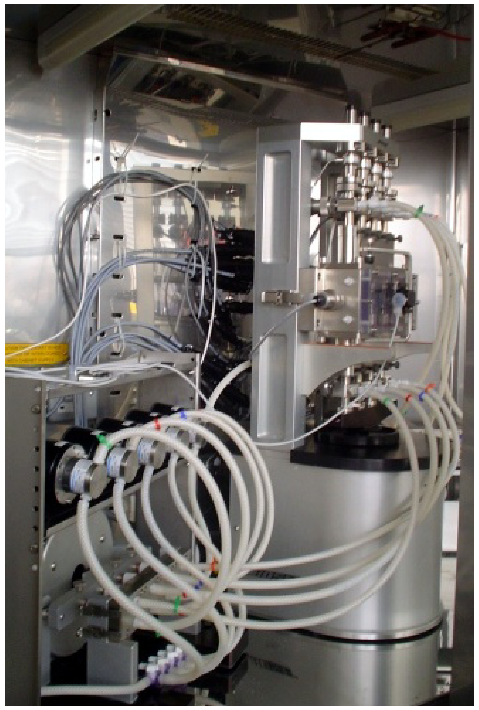
The system is made up of several components: the hydrostatic chamber, a set of mean flow pumps, the pulsatile unit, restriction valves, as well as an axial compression unit. The entire system is housed in an incubator, Gallenkamp SGC110 (Weiss Gallenkamp, Loughborough, UK).
Figure 1 shows the bioreactor assembly in the incubator.
Figure 1.
The tri-axial bioreactor.
Figure 1.
The tri-axial bioreactor.
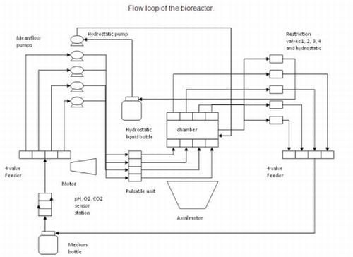
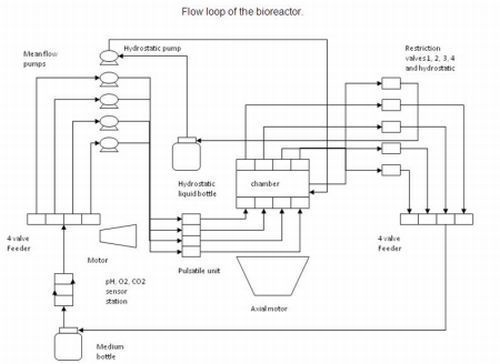
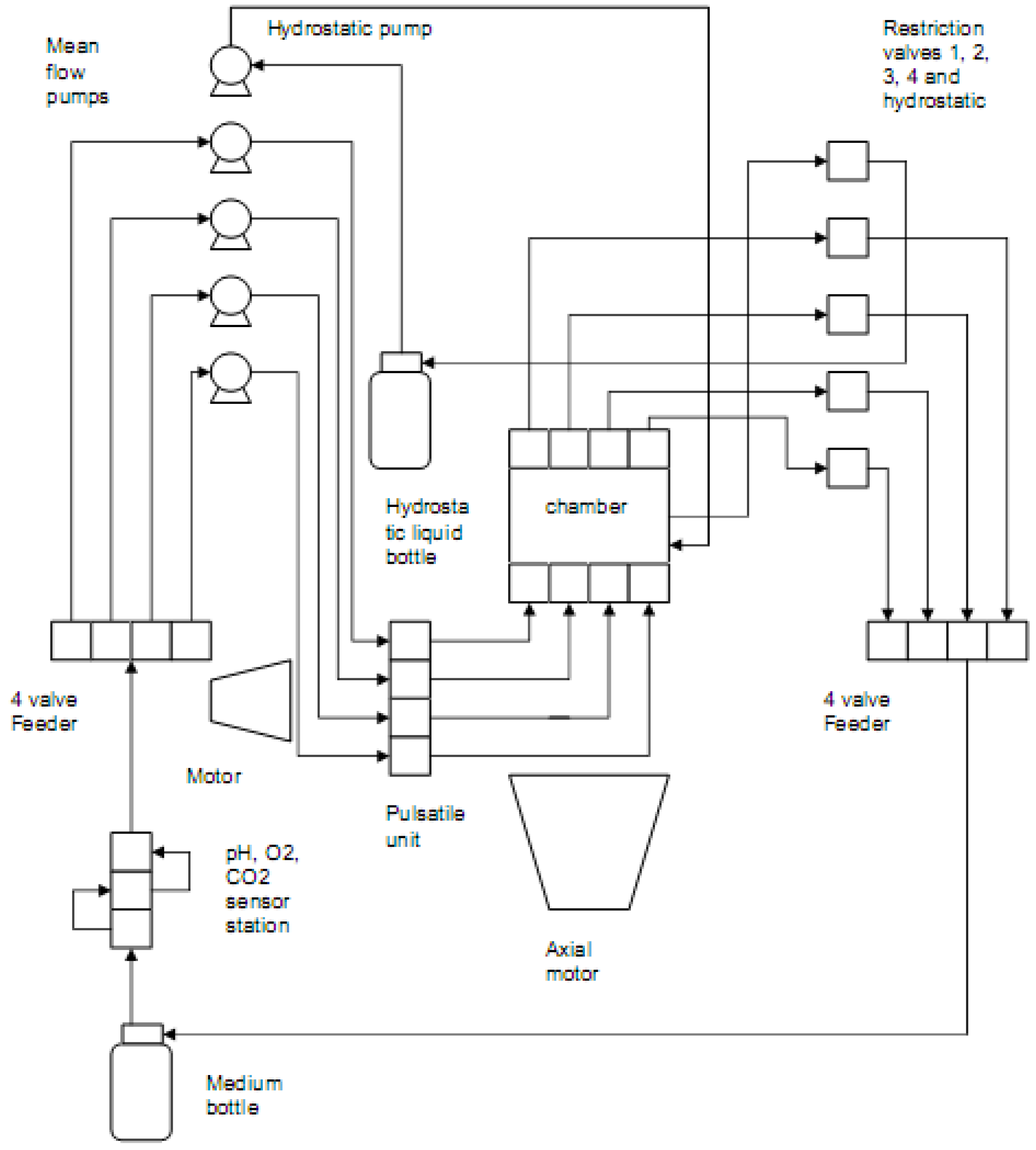
2.1. Flow Loop of the System
The diagram below (
Figure 2) shows the flow loop of the system.
Figure 2.
Flow loop of the system.
Figure 2.
Flow loop of the system.
In the first flow loop, media from the feed reservoir is drawn by the pumps and passes through the in-line sensors which monitor the pH as well as oxygen and carbon dioxide levels in the liquid. The media is split into four channels, each of which is fed into the pulsatile motor through the mean flow pumps. Media is then pumped through each of the cell-scaffold constructs which are mounted onto four sets of porous platens, emulating the end plates of the intervertebral discs. Sample pressure is controlled by the restriction valves through a closed feedback loop via the software. The media is drained back into the reservoir bottle.
In a separate flow loop, the remaining pump drives water from a second reservoir into the hydrostatic chamber. The hydrostatic pressure also is controlled by manipulating the computer-controlled restriction valve. The water is pumped back into the reservoir.
2.2. System Specifications
The main body of the bioreactor, the axial compression unit, comprises of a linear motor and the hydrostatic chamber. The motor can deliver displacements of up to ±3 mm and has an embedded displacement transducer. In the current configuration, the platen attachments to the system only allow for compressive strain. Each sample is connected to a load cell for force measurements and has independent adjustments that allow sample preloading. The hydrostatic chamber, which encompasses the four sets of sample platens, can withstand up to 0.3 MPa of pressure.
Two types of pumps are available to provide different flow options for the system. The gear pumps allow flow of 1 mL/min to 100 mL/min while the peristaltic pumps allow flow rates as low as 5 μL/min. Flow options are activated by choosing different operating files in the WinTest® software. For mean flow of up to 10 mL/min, the pulsatile Bose linear motor can deliver a maximum of 0.6 mL/pulse in the frequency range of 0.01 to 1 Hz. Pressure within each sample and hydrostatic pressure is controlled by means of the restriction valves. A pressure transducer monitors pressure upstream and downstream of each sample as well as in the hydrostatic chamber. All transducers have a ±0.5% of full scale calibrated accuracy.
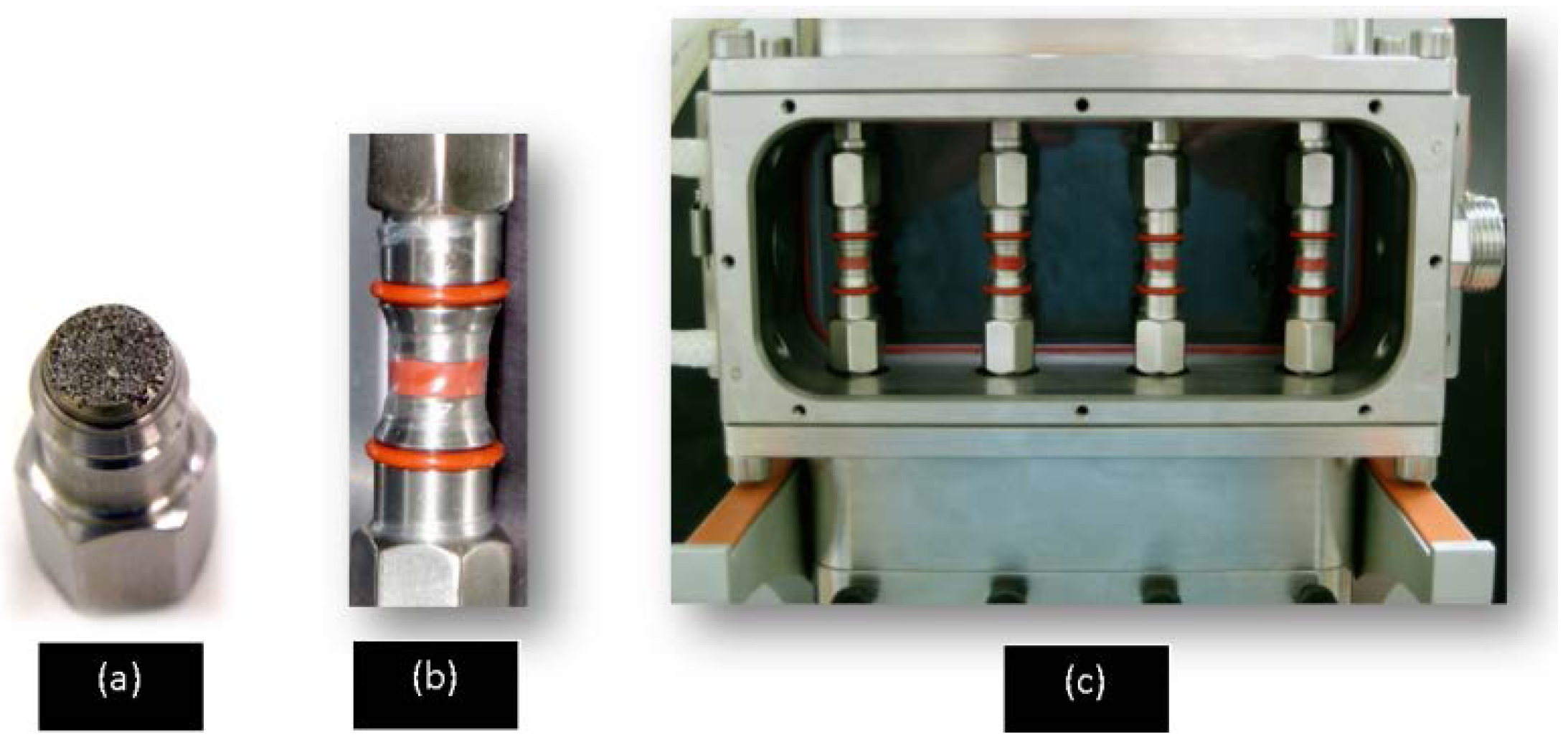
Within the chamber, each porous platen is 10 mm in diameter and has pores averaging 40 μm in size (
Figure 3a). A thin silicone membrane separates each scaffold from the water in the hydrostatic chamber. The membrane is kept in place by a set of o-rings which sit in the grooves in the platens (
Figure 3b). The window of the main chamber is removable to accommodate assembly of the platens and the scaffolds.
Figure 3.
(a) A sample platen (b) An assembled set of sample platens with membrane encased mock scaffold (c) The hydrostatic chamber with four mounted mock scaffolds.
Figure 3.
(a) A sample platen (b) An assembled set of sample platens with membrane encased mock scaffold (c) The hydrostatic chamber with four mounted mock scaffolds.
2.3. Control and Measurements
Each sample platen is connected to two pressure sensors which are in turn linked to the control processor. This allows the value of pressures at each inlet and outlet to be recorded individually in the system. It is possible to use the WinTest® software to perform Boolean operations using the readings obtained. The hydrostatic pressure is monitored in the same way with the help of a pressure sensor connected directly to the chamber.
Force sensors fitted to the top platens measure the forces experienced by the scaffolds as mechanical stimulus is applied. Each load cell can measure up to 225 N per sample. Using the WinTest® software, each driving component can be controlled to simulate mechanical stimulus of different waveforms and frequencies or a series of combinations including pulses and sinusoidal curves. The interface of the software allows all values (direct or Boolean) to be displayed in either numerical format, graphical format or both. Raw data can also be recorded and saved in a data file for further studies and manipulation. The interface of the software displays forces experienced by the scaffolds, hydrostatic pressure, as well as the uniaxial displacement and the pattern of the pulse delivered by the pulsatile motor.
3. Validation of the Bioreactor
The purpose of the validation was to ensure that the bioreactor can provide a suitable environment for mechanical stimulation of the cell-scaffold constructs. It was also critical to establish a viable standard operating procedure in setting up and maintaining the system and a protocol for cell-scaffold handling in order to prevent contamination and bacterial infection.
3.1. Cells
While the bioreactor is intended for tissue engineering of the nucleus pulposus, continuous growth of nucleus puposus cells in vitro is challenging due to their limited proliferation capability and hence such cells were not used in the initial validation of this bioreactor. A human dermal fibroblast (HDF) cell line was used as an alternative to understand and evaluate the efficacy of the bioreactor in culturing three dimensional scaffolds. HDF was chosen for its robustness, i.e., ease of culture, short doubling time and the ability to maintain the phenotype for days even at full confluence. A working bank was established by continuous culture of human dermal fibroblasts (TCSCellworks, Buckingham, UK) to passage 3. The cells were subsequently cryopreserved in liquid nitrogen and recovered from cryopreservation prior to experimental runs. Cell culture was performed in T175 cm2 flasks and cells were maintained in DMEM (Dulbecco’s Modified Eagel’s Medium, Lonza, Basel, Switzerland), containing 4.5 g/L glucose and l-glutamine, supplemented with 10% fetal bovine serum (FBS), 100 U/mL penicillin, 100 μg/mL streptomycin and 10 mM HEPES buffer solution. Media changes were performed every three days and cells were passaged by treatment with trypsin/ethylene diamine tetracetic acid (EDTA). Cells were maintained at 37 °C in a humidified atmosphere of 5% CO2/95% air.
3.2. Scaffolds
Commercially available collagen scaffolds were used to validate the bioreactor. OptiMaix-3D™ (Matricel GmBH, Herzogenrath, Germany) is derived from porcine collagen that is freeze-dried using a patented method. It is one of the first products in Europe and Australia that was used clinically for the tissue engineering of articular cartilage [
19]. OptiMaix-3D™ scaffolds were delivered sterile and ready for use and the collagen structure was consistent between samples and batches due to the highly complied quality control, offering reproducible results.
The scaffolds were 10mm in diameter and 3 mm in thickness. The scaffold Young’s modulus is approximately 5 × 10⁻³ N/mm2 when measured during 30% compression of the scaffolds, and the porosity is 98% with characteristic pore size 80 μm when measured as the shortest pore diameter in three dimension of the ellipsoidal pores.
3.3. Bioreactor Assembly and Tuning
Prior to experimental runs, a routine assembly protocol is carried out in which all components of the system are cleaned and re-assembled. At Day 0, the hydrostatic chamber, the detachable chamber window, as well as the sample platens, were sterilised in the autoclave for 15 min at 121 °C. Sacrificial samples were then mounted onto the platens. A square waveform is generated to simulate mechanical stimulation, using the WinTest
® software, proportional-integral-differential (PID) control was utilised to tune the system.
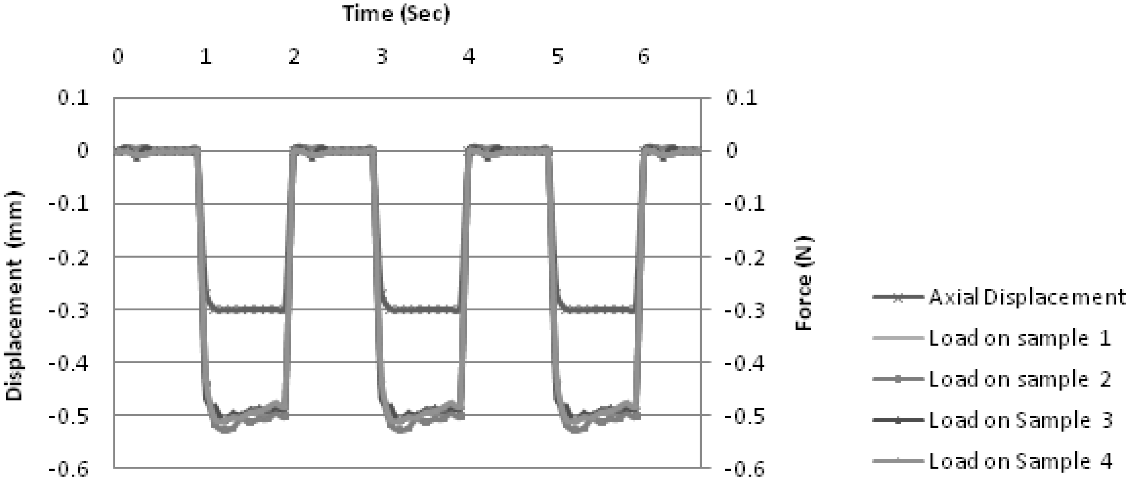
Figure 4 shows an instance of the system being tuned with sacrificial samples placed in each of the four chambers.
Figure 4.
Proportional-integral-differential tuning. In this instance, a square wave of +0/−0.3 mm in axial displacement was applied to the samples. Within WinTest® interface, the P, I and D components were incrementally adjusted until a square wave is consistently generated by the system as shown in the figure. The graph also shows the applied force (in Newtons) experienced by the samples during the tuning. All four samples show similar load values indicating that each sample platen is assembled to the same standards. Small variations in load values are expected as the quality of the collagen scaffolds may vary.
Tubing was sterilised by running 70% ethanol at 5 mL/min through the whole system for 1 h in a closed loop, and left to dry overnight. Phosphate buffered saline was then run through the system for 20 min at 2 mL/min. Subsequently, the four sample flow loops were primed with DMEM at 1 mL/min for 20 min.
3.4. Experimental Setup
HDF at passage 5~6 were seeded onto the OptiMaix™ scaffolds. Cells were detached from the flask using trypsin/EDTA and counted using a hemocytometer. Cell suspensions were centrifuged and resuspended in culture media. Scaffolds were then inoculated with cell suspension at a density of 1.5 × 10⁶ cells per scaffold. Constructs were incubated for 10 min at 37 °C before being replenished with cell culture media.
After cell seeding, cell-loaded scaffolds were cultured under standard conditions in a static incubator for 7 days to allow initial cell attachment. Sterile sample platens (with membranes attached) were brought into a Class II biosafety cabinet. Sample platens were placed in petri dishes, and media was pipetted dropwise onto the top of the sample platens to bleed air from the porous core. These scaffolds were dynamically stimulated for a further 7 days under the following conditions: 0.20 mL/min perfusion and 5% compression at a frequency of 0.01 Hz at atmospheric sample pressure. Four other scaffolds were cultured under standard static conditions as a control.
3.5. Cell Proliferation Assay
Cell proliferation was assessed by performance of a Non-Radioactive Cell Proliferation Assay (MTS Assay) (Promega, Fitchburg, WI, USA) according to manufacturer’s instructions. The MTS assay consists of a tetrazolium salt ((3-(4,5-dimethylthiazol-2-yl)-5-(3-carboxymethoxyphenyl)-2-(4-sulfophenyl)-2H-tetrazolium)) that is bio-reduced by proliferative cells to a formazan product. The MTS compound is converted into soluble formazan by dehydrogenase enzymes found in metabolically active cells causing a colour change within the media. The quantity of formazan can then be measured by absorbance at 490 nm and is directly proportional to the number of living cells in culture.
Briefly, the MTS solution was added to the media covering the scaffolds at a fixed concentration. Scaffolds were then incubated for 1 h at 37 °C until colour change occurred. Absorbance was measured at 490 nm using a microplate reader ELX800 (Biotek, Bedfordshire, UK).
3.6. Scanning Electron Microscopy
In order to visualise the colonisation of cells into the scaffolds, scanning electron microscopy (SEM) was carried out after the experiment. To prepare for SEM, samples were fixed in 3% glutaraldehyde in 0.1 M sodium cacodylate buffer (5 mL) for 2 h. The samples were washed twice in 0.1 M sodium cacodylate buffer (5 mL) for 20 min and then placed in 2.3 M sucrose (5 mL) for 24 h at 4 °C.
Samples were subsequently frozen and fractured in liquid nitrogen. The fractured pieces were thawed in distilled water, and immersed twice in distilled water for 15 min each. Subsequently, the fragments were placed in increasing concentrations of acetone (30%, 50%, 70%, 90% and 100%) three times at each concentration for 15 min. The samples were critical point dried in CO2 using a Polaron E3000 critical point drier (Quorum Technologies, Ltd., Guelph, ON, Canada) and mounted on 12.5 mm pin stubs using adhesive carbon tabs (Agar Scientific, Stansted, UK) and gold sputter coated using a Polaron E5100 sputter coater (Quorum Technologies, Ltd., Guelph, ON, Canada). The coated fragments were viewed in an FEI Quanta 200F field emission scanning electron microscope (FEI Company, Hillsboro, OR, USA) using high vacuum mode and an accelerating voltage of 5 kV.
4. Results and Discussion
OptiMaix-3D™ scaffolds indicated cell attachment and spreading within the scaffolds. Striations were observed on the dynamic samples, which were likely due to handling during loading and unloading of the scaffolds into the bioreactor. Numbers of viable, proliferative cells were assessed via an MTS assay, directly after seeding the scaffolds and after 4 days, for scaffolds that had been cultured statically and dynamically. Due to the low number of samples available for measurement, results of the MTS assay were used only as an indicator. There was indication that cell viability immediately after scaffold seeding remained high but after prolonged culture, both static and dynamic, viability was dramatically reduced. This may have occurred for a variety of reasons such as cells or components of the extracellular matrix being washed out during media changes and nutrient deficiencies in the scaffold core. Under SEM, OptiMaix-3D™ scaffolds showed matrix deposition under both conditions (
Figure 5). Matrix deposition was the highest on the outer surfaces of scaffolds cultured under static conditions (
Figure 5a).
Figure 5.
SEM images of OptiMaix-3D™ scaffolds—At the surface after static culture (a), after dynamic culture (b), and sample fragments after static culture (c), after dynamic culture (d). The scale bar represents 100 μm.
Figure 5.
SEM images of OptiMaix-3D™ scaffolds—At the surface after static culture (a), after dynamic culture (b), and sample fragments after static culture (c), after dynamic culture (d). The scale bar represents 100 μm.
The lack of homogeneity in cell distribution and cell detachment in dynamic culture could be a consequence of shear stress caused by flow path tortuosity within the porous structure, as well as the collapse of the porous structure due to the continuous stress during mechanical stimulation. Engineering control of the interaction of structure and mechanical properties of scaffolds with the loading regime to achieve optimised mass transfer to the cells is one of the key challenges identified in design of mechanical stimulation bioreactor [
18,
20]. Further investigations show that media pH of the near the scaffolds became more alkaline over the period of dynamic culture, as indicated by the media colour change. This could be attributed to a low level of carbon dioxide within the tubing of the system. While sensors are in place to track the carbon dioxide and pH levels of the air as well as the media at the inlet, it is still difficult to gauge the values of these parameters where the scaffolds are. Further it is likely that the long and complex flow loops compromised the diffusion of carbon dioxide into the culture medium it was therefore necessary to adjust the pH value of the medium with a bicarbonate and carbon dioxide buffering system to levels required for cell processing.
Creating the optimal environment for cell survival and growth remains a key issue in the field of tissue engineering. Combining cells, scaffolds and bioreactor environment can present many complicated issues. Achieving a uniform cell distribution throughout the scaffold has proved to be a challenge in other investigations [
21,
22]. This study used a simple technique to seed the cells on the scaffold which resulted in the majority of cells remaining at the edges and surface of the scaffold. The use of moderate centrifugal force, as demonstrated by Yang
et al., or a more complicated two-step seeding procedure may improve cell distribution in future investigations [
23].
5. Conclusions
We have demonstrated the instruction and operation of a three-dimensional cell culture system. The intent of the bioreactor was to emulate more closely the physiological conditions experienced by the intervertebral disc; this however leads to significant mechanical complexity that is exacerbated by the need to maintain sterility. There is therefore a requirement to both optimise culture conditions and the mechanical environment.
The current research also highlights the potentially compromising effects of dynamic culture on cell viability. Cell viability immediately after scaffold seeding remained high but after prolonged culture, both static and dynamic, the viability had fallen dramatically. This may have been for a variety of reasons, including: cells being washed out during media changes; low cell survival after seeding and nutrient deficiencies in the centre of the scaffold. Achieving a uniform cell distribution throughout the scaffold has proved to be a challenge in other investigations [
21,
22], and within this study using a simple cell seeding technique did not produce the most optimal results, with the majority of cells remaining at the edges and surface of the scaffold. It was initially expected that mechanical stimulation would promote the production of proteoglycans, the necessity to maintain perfusion flow through the system however has meant that it has proven difficult to retain them within the system.
As bioreactors attempt to more closely replicate physiological conditions, trade-offs are required between bio-mimetic aspirations and the practical limitations of engineering, both design and machine building. While the “first generation” bioreactor system delivered by the supplier is state-of-the-art technology, continuous improvements in design and operational protocols will be necessary to achieve robust experimental procedures and realize the original intent of developing tissue-engineered nucleus pulposus.
In order to understand the system better and improve its efficacy, studies are currently being carried out using human mesenchymal stem cells (hMSC) in combination with collagen and polymer scaffolds. Initially developed for tissue engineering of the disc, this complex bioreactor system affords the opportunity to investigate the effect of different combinations of mechanical stimulus (steady and pulsatile flow, circumferential hydrostatic pressure and axial compression) on various scaffold and cell types while characterizing tissue mechanical properties and monitoring cellular metabolic activity.


