1. Introduction
In recent public funding projects (e.g., F
3 Factory [
1], CoPIRIDE [
2]), the first examples of modular and continuously operated small-scale plants (MCSPs) have been evaluated and confirmed to be beneficial in a technical and economical manner [
3,
4]. The presented prototypes represent first-of-its-kind plants and demonstrate the general feasibility of the technology. To fully exploit the potential of MCSPs, the entire development chain, starting with the chemical process development and conceptual process design to engineering and construction, has to be supplemented with innovative methodologies. These should take into account the main drivers for the utilization of future production concepts. For some products, “time-to-process” is of great importance for enabling market entry. This can be true for products with a short product lifespan in volatile markets, as described by I.V. Gürsel
et al. [
5]. Other products, like high value pharmaceutical drugs, benefit from continuous processing and fast process development by using the same MCSP for the early supply of kilogram-samples for clinical trials and for later market entry. MCSPs also provide a flexible platform concept [
6] for the production of different lot sizes of highly customized products. Due to continuous processing, lot size can be adapted by the campaign runtime. A range of similar products (e.g., polymers of different molecular weight distribution), which are adapted to exactly meet customer needs, can be realized by utilizing the ability to reconfigure single modules within MCSPs. Singh
et al. [
7] describe a process reconfiguration strategy for substrate adoption that could be applied here. Furthermore, the compact framework of an MCSP provides an ideal infrastructure for the implementation of milli- and micro-structured equipment, enabling the integration of process-intensified equipment into a production environment. The technology offers access to new synthesis routes and process windows that are not suitable for classical batch operation or that provide better product quality than conventional processing [
8,
9].
In order to meet the named requirements for a shortened development time and increased plant flexibility, and additionally, enabling the use of modern process equipment, the concept of modular process development [
10] utilizing predefined and intensified equipment will be addressed in this article. A methodology for the selection of technical reactors in the early stages of conceptual process design is presented exemplarily, which aims at supporting the data acquisition for reaction systems and process scale-up. By identifying the most critical technical parameters and promising reactor technologies in the early stages of development, the steering of lab development and scale-up can be facilitated. The methodology aims at choosing the optimal solution out of commercially available equipment rather than engineering new, highly optimized equipment. These already existing and tested devices often have inherent numbering-up/scale-up concepts available, which can be combined with a modularized plant framework to simplify and speed up implementation into MCSP.
2. Modular Plant Design and Predefined Equipment
The term plant modularization is widely used within literature, describing different possible layers for the implementation of modularity in plant engineering and construction [
4,
11,
12,
13]. Hence, for the MCSP, the applied definition of modularity shall be specified in this chapter. According to
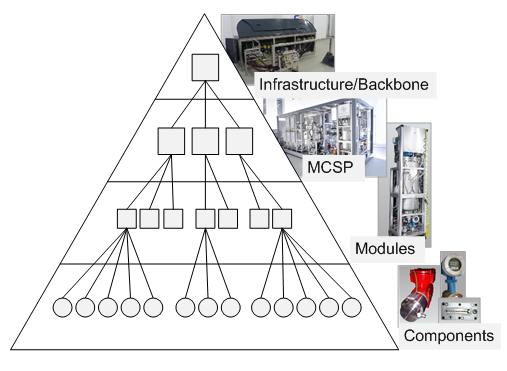
Figure 1, multiple MCSPs can be integrated into one backbone facility to provide the needed technical and logistic infrastructure for the processes and to reduce the overhead operation expenditures (e.g., staff, logistics, storage and civil engineering). The backbone facility can be a greenfield solution or likewise integrated into an existing (batch) facility.
Figure 1.
Hierarchical structure of the physical elements within modular and continuously operated small-scale plant (MCSP) planning.
Figure 1.
Hierarchical structure of the physical elements within modular and continuously operated small-scale plant (MCSP) planning.
Individual MCSPs can be fitted into ISO transport containers if the preassembly of the plant, location flexibility and an easy process redesign are of some importance. The container framework also provides all the needed process utilities, the overall process control and a grid for the positioning of process modules within its compact footprint.
2.1. Modular Equipment
These two top layers are not regarded as modular. The modular design is applied to the next layer of the plant. Functional units of the process are clustered into modules, where one module consists of the main equipment, which provides the desired unit operation together with all needed peripheral components (e.g., pumps, heat-exchangers, piping, process control components). To be compatible with one another, the construction of each module follows certain design rules. Each module is constructed into a transportable skid in which the footprint of the skid is a multiple of a discrete grid size, which gives flexibility for the arrangement and rotation of adjacent modules. To enable fluidic and electrical connections, predefined compartments, as well as standards for the final interconnection of the modules are specified, and near-field process control systems are provided, which can be connected to the overall process control system.
The main and peripheral equipment within the modules are described in detail at the component layer. The single components are combined to achieve a desired module operation window defined by technical parameters (e.g., ranges for temperature, pressure, flow rates, material grades). Thereby, within one module, some components are exchangeable to adapt different operation conditions. Especially for the main equipment, a certain free space inside each module is reserved during the initial planning, which offers the possibility of integrating various equipment into the same base module, in order to facilitate the reuse of already planned modules.
In addition to these physical properties of a module, a documentation package containing all necessary documents for planning, construction and operation is generated for each module. Besides typical engineering documents (e.g., P&ID, instrument datasheets), it also includes templates for the process control system, a safety and reliability assessment, a list of possible configuration alternatives and simulation models, which describe the resulting operation window. A corresponding definition of module planning documentation is also described by Bramsiepe
et al. [
10].
As a result of the described modularity, different possibilities for the reuse of information and equipment can be utilized to speed up the “time-to-process”. If process specifications for a given task fit into an already existing module (referred to as the “base module”), it can be reused without modification. Furthermore, the reproduction of an existing base module from a documentation package without major modifications is possible, which enables savings in the development and construction time and expenditures. If no existing or planned module meets the specification of an actual process task, a new module has to be designed. Therefore, the documentation package of the best fitting base module is reused by specifying different components where necessary. The method presented in the following aims at supporting the selection of the main equipment within a base module by using predefined process equipment.
2.2. Predefined Equipment
The above-mentioned concept of a configurable base modules can be applied for several unit operations within the MCSP. Especially for the reaction steps of a process, it is augmented by a broad variety of commercially available technical reactors for continuous processing, including intensive mixing, heat exchange and residence time applications. If the peripheral equipment of a reaction module is chosen carefully, it can be used for a wide range of applications within a defined process task (e.g., reaction systems defined by a phase system). For basic operation conditions (e.g., temperature, pressure, volumetric flow rate, viscosity), a range of one or two magnitudes for each parameter is achievable using the same peripheral equipment. All other operation parameters (e.g., residence time, mixing intensity, heat removal) are only dependent on the main apparatus of the module, which can be chosen arbitrarily within the geometrical boundaries of the base module.
In a classic continuously operated, large-scale plant, the reactor is often intensively optimized and individually designed for a particular application and operating point. Numerous reactor design methods, like heuristic approaches, dynamic optimization approaches, attainable region methods, rigorous optimization approaches (e.g., superstructures) and the systematic staging approach, are presented in the literature, as reviewed by Peschel
et al., and present a rigorous multi-step optimization approach [
14]. A recent method presented by Patel
et al. [
15] adopts a modular approach for tubular reactor design. These methods show an increasing mathematical complexity during the last five decades and usually aim at designing strongly optimized, but individually constructed reactors. To achieve this, a broad variety of process information (especially a mathematical description of the reaction kinetics) is required.
In contrast to this, the approach presented here aims at supporting the early process development and scale-up from lab to productive environment. Hence, it has to deal with increasing system knowledge starting with rudimentary information to support early lab development. To further decrease the development time, the usage of predefined equipment is intended. Predefined equipment can be represented either by an apparatus being already in stock from a former process (reutilization) or by a commercially available standard apparatus. This also affects the design procedure, due to the fact that the geometries of the available reactors are already fixed. Instead of designing an optimized new piece of equipment, an existing apparatus has to be identified from a database, sufficiently approximating an optimal reactor for the process. Some manufacturers already provide a systematic scale-up or sizing approach for their own equipment, which can also be regarded in the selection process. This can address the parallel or serial connection of basic reactor elements or system-inherent scale-up strategies, as reported by Roberge and Kockmann
et al. [
6,
16,
17,
18], to select the right equipment to meet the process requirements. The selection of equipment from a fixed set of devices and their interconnection allows for a quicker engineering and construction compared to designing specialized equipment. Otherwise, an increased willingness to compromise with respect to the optimal technical process is needed. If a predefined reactor is chosen, for example, the device throughput and mean residence time cannot be chosen independently. For many reactions, the method presented in the following chapter can nonetheless lead to a sophisticated technical solution.
3. Selection of Predefined Plug Flow Reactor Equipment
The methodology will focus on the selection of plug flow reactor equipment, which is suited to operate homogeneous liquid-phase reactions in an MCSP. As a result, favorable technical reactor designs are suggested. Experimental validation and further specifications of the equipment (e.g., material grade, chemical resistance, safety installations) have to be considered subsequently. The reactor selection methodology presented in this paper requires data from different origins to decide about the technical ability of the reactor system and to identify the most promising ones. From the chemical process development, basic information about the chemistry of the process (stoichiometry, stoichiometric ratio, solvent system, reaction temperature), the mean physical properties of the reacting fluid (density, viscosity, heat capacity, molar masses), the chemical properties of the system (heat of reaction/adiabatic temperature rise, operation temperature interval, reaction kinetics) and the desired reactor concept [
19] (plug flow or total back-mixing in the reactor) can be gained. The conceptual process design and the process flowsheet provide information about the state of the feed stream (mass flow rate, composition, temperature, pressure) and give general targets for the outlet stream (targeted conversion/yield). An equipment database provides information about the available predefined reactor systems. For each reactor system, a dataset consisting of geometry information (length, diameter, volume), the allowed operation conditions (feasible operation pressure or temperature), and specific correlations (pressure drop, heat transfer) is stored in the database (
cf.
Table 1).
The database information for process and equipment can be accessed and processed by a user-guided software tool. Suited mathematical models are used to calculate the characteristics of the investigated process simultaneously in various reactor systems. The characteristics can be compared with boundary values connected to the apparatuses or the reacting fluid, which must not be violated. As characteristics, the mechanical and thermal stability of the reactor in operation, a sufficient initial mixing of the reactants in the reactor and the thermal stress to the reacting fluid has to be analyzed. Such a technical boundary will be called the “technical criterion” in the following. Further “performance indicators”, like the high conversion of the reactants, the high selectivity to the desired product(s), the moderate operation conditions (low required inlet pressure, ambient required temperature of the heat transfer medium), favorable flow conditions and, especially in case of the MCSP, a sufficiently low space demand of the main reactor equipment in the reactor module, can be used to revise and rate the technical ability of the reactor systems. Beside all these aspects ensuring the technical ability of a certain reactor system, investment costs and the time required for delivery and construction have to be considered, too. The reuse of an already existing reactor module might be of economic advantage over purchasing new (optimized) systems, due to the time-saving aspect. Operating costs are assumed to be less depending on the choice of the main equipment. Thus, operating costs will not be analyzed in detail here, although it might be generally favored to choose a reactor, operating at moderate conditions as mentioned above, resulting in lower energy demand.
3.1. Availability of Process Data
The full range of process information mentioned above is often not available from the start of the process development for a new fine chemical/pharmaceutical product. Especially measuring the kinetics of the reaction are often more complex and time-consuming, compared to physical properties and other chemical properties. Thus, the reactor selection methodology presented here is divided into two parts. The first part works without exact kinetic information. In the second part, reaction kinetics data are used to deeply analyze the pieces of equipment being preselected in the first part.
3.2. Reliability of Equipment Data
From the equipment point of view, basic information about all mentioned areas (geometries, operation limits, important transport correlations) has to be available to include a reactor system into the database and to consider its application in the MCSP. The reliability of these data depends on the way it was gained. Geometry information taken from detailed mechanical drawings of the reactor or empirical correlations fitted to experimental data will be more accurate than rough assumptions based on catalogues of the equipment manufacturers or literature correlations being suitable for similar channel geometries.
Thus, the reactor systems being implemented in the equipment database use datasets of diverse reliability. The comparison of the results of different reactor systems has to be executed with appropriate caution. A demand for simple, but reliable and experimentally validated, operating correlations (pressure drop, heat transfer and mixing behavior) for predefined reactor equipment can be stated. One the one hand, that information can be gained from operational experience, using the equipment in an MCSP. On the other hand, an intensified cooperation of equipment manufactures and equipment operators is needed.
Table 1.
Stepwise methodology to preselect standardized technical plug flow reactor systems from a database.
Table 1.
Stepwise methodology to preselect standardized technical plug flow reactor systems from a database.
| Level of detail | Technical criterion | Process data needed | Equipment data needed | Operation data available |
|---|
| no reaction kinetics required | presettings and prerequisites | reaction stoichiometry
molar masses
mass flow rate
inlet composition
inlet temperature
required outlet pressure | database of existing and/or commercially available and/or promising new plug flow reactor systems | |
| 1. residence time performance indicator | allowable residence time interval reaction timescale A/B/C [20]
mean density of reacting fluid | internal volume of the reactor | (adapted) volumetric flow rate mean residence time |
| 2. operating pressure technical criterion | mean viscosity of reacting fluid | hydraulic diameter
channel length
channel cross-section area
pressure drop correlation | flow velocity
Reynolds number
pressure drop |
| 3. operating temperatures technical criterion | allowable temperature interval of reacting fluid
mean heat capacity of reacting fluid
mean heat conductivity of reacting fluid
adiabatic temperature rise | Nusselt number correlation (internal heat transfer)
external heat transfer estimation heat conductivity (wall material)
wall thickness
max./min. operating temperature | heat transmission coefficient
characteristic temperature difference to heat transfer fluid (HTF) |
| reaction kinetics required | 4. kinetics of mixing and reaction technical criterion | kinetic constant at reaction temperature reaction order | | time constant of mixing
time constant of reaction |
| 5. safety and hotspot formation technical criterion | pre-exponential factor (Arrhenius) energy of activation | | safety margin to runaway regime
concentration and temperature profile in reactor (hotspot temperature)
conversion, yield |
3.3. Stepwise Reactor Selection Methodology
The methodology of selecting technically suited, predefined plug flow reactor equipment from a database will be described in more detail in the following. An overview about the stepwise procedure is presented in
Table 1. Each step requires more data of the particular process and of the predefined equipment. Due to the fact that process data has to be gained during process development (see Chapter 3.1), the order of selection steps is adjusted to an increasing demand of process data and to its expected availability during the approaching process development project. If, e.g., viscosity and heat capacity data of the reacting fluid is unavailable for a new process in an early stage of the process development, suitable reactor setups can already be preselected from the equipment database, based on throughput and mean residence time only.
Before utilizing the reactor selection methodology, a reactor database and basic information about the feed stream to the reactor have to be provided (see
Table 1, presettings and prerequisites). The computer-aided execution of the reactor selection methodology allows for the simultaneous analysis of multiple reactor systems. Exclusion of reactor systems due to technical reasons is the main focus of each step of the reactor selection methodology. In addition, further operation data (e.g., flow velocity, Reynolds number, heat transmission coefficient) is gained for every reactor being analyzed (see
Table 1).
3.3.2. Step 2: Operating Pressure (Technical Criterion)
The highest pressure in a liquid-phase plug flow reactor is expected at the inlet (Equation (4)), whereas the outlet pressure (reaction pressure pR) is defined by the laboratory development. It can be elevated from atmospheric pressure, e.g., to suppress the vaporization/desorption of one or more components from the reacting fluid.
The pressure drop depends on the particular reactor system (channel geometry, volumetric flow rate) and the properties of the reacting fluid (density, viscosity). It has to be estimated by suitable pressure drop correlations, which have to be present in the reactor database. The inlet pressure has to be compared to the allowable maximal pressure inside the complete reactor module, which is defined by the particular reactor itself, fittings, piping, gaskets, instruments or the pumping systems available in the reactor module (Equation (5)). It must not be violated.
3.3.3. Step 3: Operating Temperatures (Technical Criterion)
Temperature management is a key issue for processing chemical reactions at a technical scale. This paper is focused on reactors being cooled or heated fluidically. Allowable minimal and maximal temperatures of the reacting fluid (e.g., freezing point, boiling point, decomposition temperature) and of the equipment (e.g., of reactor, fittings, piping, gaskets, instruments) can be defined. These limits must not be violated either by the temperature of the reacting fluid or by the temperature of the heat transfer fluid (HTF). The heat transfer coefficient describing the internal heat transfer from the reacting fluid to the wall can be calculated by suitable Nusselt number correlations for each reactor, which have to be present in the reactor database. Often, the contributions of conduction through the wall material and of the heat transfer from the wall to the HTF cannot be calculated exactly. The contributions can be either neglected (assuming good conduction and heat transfer to the HTF), or an assumption is made that the contributions to heat conduction and external heat transfer are a multiple,
CRth,i, of the internal heat transfer resistance (Equation (6)) [
17].
A simplified black-box energy balancing model has been developed in order to compare the heat transfer abilities of different reactors. The flow conditions being defined before and the specific surface area of each reactor are included in the model. The model copes without a mathematical description of the reaction kinetics, but uses information about the heat of the reaction, respectively the adiabatic temperature rise that is accessible by reaction calorimetry. The aim of the black-box model is to calculate a characteristic temperature difference to the HTF at which the total heat of the reaction (complete conversion assumed) can be transferred to the HTF (Equation (7)).
Therefore, the outlet temperature of the reactor will be equal to its inlet temperature. The temperature of the heat transfer medium is assumed to be constant along the reactor.
The process temperatures, TR and THTF,i, can be compared to the temperature limits being defined before, to decide whether the reactor is technically suitable or not (Equation (8), technical criterion).
In addition, the reactor enabling the lowest characteristic temperature difference according to amount |ΔTHTF,i| is most suitable with respect to heat transfer. Thereby, technically suitable reactors can be compared to each other (performance indicator).
3.3.4. Step 4: Kinetics of Mixing and Reaction (Technical Criterion)
In technical systems, sufficient mixing of the reactants has to be ensured by the reactor system itself or by a mixing unit connected upstream of or within the residence time channel. In order to roughly check the mixing properties of the different reactor systems at chosen operation conditions, a short-cut method based on characteristic time scales is applied to the reactor selection method. From this step on, information about the reaction kinetics is necessary.
Therefore, the characteristic time constant of the reaction (Equation (9)) has to be compared to the characteristic time constant of micromixing by engulfment (Equation (10)), which is dominating in a small-scale channel flow [
22]. The time constant of the reaction is equal to the reaction half-life in the case of a second order reaction. The time constant of micromixing depends on the mean kinematic viscosity of the reacting fluid and on the energy dissipation rate of the reactor, which can be calculated by means of the pressure drop (Equation (11)).
Comparing these two characteristic time constants to the mean residence time of the reactor (see Step 1), two different regimes can be distinguished:
a reaction-dominated regime (tE,i ˂ tR ˂ τi)
a mixing-dominated regime (tR ˂ tE,i ˂ τi)
In both cases, the dominating phenomenon proceeds faster than the mean residence time of the reactor. Thus, sufficient progress of the reaction at the reactor outlet can be assumed. In the case the residence time is shorter than the characteristic time constant of the reaction (τi ≤ tR), the lower boundary, τmin, of the residence time interval (see Step 1) should be revised. If the process is dominated by mixing (tR ˂ tE,i), but the mixing will not be completed in the reactor (τi ˂ tE,i), it can be advantageous to implement a mixing unit upstream of the reactor. This decision on the case is regarded as a ‘technical criterion’.
Moreover, controlling the residence time distribution (RTD) behavior of a continuous technical plug flow reactor is of high importance. A majority of reactions generally benefits from a well-defined and narrow RTD. A high local reactant concentration level is favored to accelerate the reaction kinetics and to suppress side/subsequent reactions. Exceptions (e.g., autocatalytic reactions) are described in Levenspiel’s textbook [
19]. Modern flow reactors are designed to provide intensified radial mixing, resulting in a concentration profile close to ideal plug flow behavior, even in the laminar flow regime. This is often achieved by the milli- or even micro-structured channel geometries (short diffusion lengths) and can be further optimized by the curved channel flow (Dean vortices) or split-and-recombine techniques, like static mixers.
Above all, it appears difficult to quantitatively predict the plug flow behavior of most technical reactor systems, taking the geometries, fluid properties and process flow rate into account. Elaborate experimental characterization or CFD flow simulation for each reactor system would be necessary to create short-cut models, being comparable to the model of Taylor and Aris [
23,
24] for straight pipe flow, to estimate the Bodenstein number of modern flow reactors. Therefore, the approach presented in this paper roughly assumes that the RTD of the analyzed reactors is sufficiently close to the ideal plug flow. Defining a standardized methodology to estimate the RTD of various technical reactor systems and their combinations in an MCSP will be a challenging goal for future research.
3.3.5. Step 5: Safety and Hotspot Formation (Technical Criterion)
In the last step of the reactor selection methodology, the mathematical description of the reaction kinetics is used to evaluate the dynamic heat release/heat demand of the reaction. This step is important, especially for highly exothermal reactions, which might cause a safety issue, due to a reaction runaway. Additionally, decomposition of one or more components of the reacting fluid or undesired reactions might occur if elevated temperatures appear at the hotspot in the reactor.
Two methods are implemented in this step of the methodology. Firstly, a safety screening by the use of the short-cut criterion developed by Barkelew for the zeroth-order reaction and extended by Renken for positive order reactions [
25]. Thus, unsafe reactor setups can be eliminated before a simulation of the axial concentration and temperature profiles is carried out to calculate the output conversion and the hotspot temperature of the reactor. The inlet temperature and the temperature of the heat transfer medium is set to the value of
TR for both calculation steps.
For applying the Barkelew-Renken (BR) criterion (Equation (12)), the energy of activation of the reaction is used to calculate the heat production potential of the reaction (Equation (13)). By the characteristic time constant of the reaction (Equation (9)) and the characteristic time constant of cooling (Equation (14)), the cooling intensity can be defined (Equation (15)). The constant,
b, depends to the reaction order and was defined by means of numeric analysis [
25].
In the case of violating the BR criterion, the reactor operates in a window of parametric sensitivity. Small deviations in reaction temperature lead to a strong increase of the hotspot temperature in the reactor or even to a complete runaway of the reaction. Thus, reactor systems violating the BR criterion will be excluded from the list of technically able reactor systems (technical criterion).
The resulting technically applicable reactor systems will be simulated by a simplified axial reactor model. Therefore, the balances for all components, j (Equation (16)), and the coupled energy balance (Equation (17)) of each reactor system, i, have to be solved numerically. Ideal plug flow behavior in the reactors is assumed for the differential modelling.
From the resulting axial temperature profile, the hotspot temperature, THS,i, can be derived. This temperature can be significantly higher than the temperatures regarded in Step 3 using the black-box model. Thus, the criterion of Step 3 has to be adapted and checked again (Equation (18), technical criterion).
As a result, the simulation conversion and yield at the reactor outlet can be gained. Based on this information, promising reactors can be compared and further optimized.
3.4. Scale-Up and Numbering-Up Concepts
As mentioned above, some commercially available reactor systems have system-inherent numbering-up concepts available. Even if the geometries (volume) of a pre-defined reactor element are fixed, parallel and/or in series, the interconnection of multiple reactor elements is an opportunity to increase the volume/residence time and the free cross-section area of the reactor system, being passed through by the reacting fluid flow. Thus, the interconnection of multiple equal reactor elements represents a degree of freedom for designing the reactor concept for the particular process, considering predefined equipment.
To consider interconnection concepts in the reactor selection methodology presented above, an interconnection matrix is automatically gained for each reactor system in the reactor database (
Figure 2). Database information about the available, single reactor elements correspond, e.g., to the number of reactor elements in stock and ready for use, or to the number of reactors fitting into a basic reactor module, due to the outer dimensions of the main apparatus. These database entries can be individually adapted to the particular project. Parallel interconnection can be prohibited from the beginning, e.g., if maldistribution [
26] is an issue.
Figure 2.
Interconnection matrix for different reactor systems exemplarily having five single reactor elements available.
Figure 2.
Interconnection matrix for different reactor systems exemplarily having five single reactor elements available.
Each valid entry in the interconnection matrix represents one possible interconnection of reactor elements, which has to be analyzed by the criteria described above. Thereby, the most promising setup of each reactor system can be identified.
System-inherent scale-up concepts, like reactor systems of different scales (lab, pilot, production scale; see Chapter 2.1), can be regarded by the selection methodology, too. To do so, a database entry has to be implemented for every scale of the reactor system.
4. Application Example: Reactor Selection Methodology
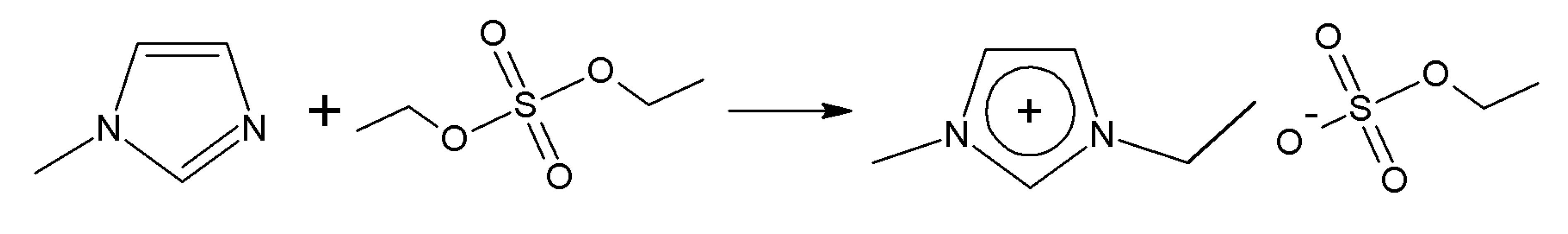
In order to demonstrate the stepwise approach of the presented reactor selection methodology, a simplified example based on a well-known reaction from the literature—synthesis of the ionic liquid (IL), ethylmethylimidazole ethyl sulfate [EMIM][EtSO
4] (
Figure 3) [
27,
28]—will be presented in the following chapter. The reactor technology for this reaction has already been intensively investigated and optimized [
29,
30]. In this chapter, the presented methodology will be used to select a promising setup of predefined reactors, being comparable to the optimized and experimentally validated reactor concepts from literature.
Figure 3.
Alkylation of 1-methylimidazol (MIM) with diethyl sulfate (DES) to ethylmethylimidazole ethyl sulfate ([EMIM][EtSO
4]) [
28].
Figure 3.
Alkylation of 1-methylimidazol (MIM) with diethyl sulfate (DES) to ethylmethylimidazole ethyl sulfate ([EMIM][EtSO
4]) [
28].
ILs are organic salts with a low melting point and, thus, are often liquid at room temperature. They are known as innovative solvents with beneficial attributes (negligible vapor pressure, designable molecule structure) over conventional solvents and are thus promising for use in chemical processes [
31]. For this example, an MCSP process will be assumed, using [EMIM][EtSO
4] as a solvent for a reaction step. In continuous operation (24/7), a leaching of the IL takes place, and thus, an amount of 300 g/h of IL has to be provided to restore the losses. A continuous synthesis of the [EMIM][EtSO
4] inside the MCSP shall be investigated, designing the reactor with existing, predefined equipment.
The synthesis reaction of [EMIM][EtSO
4] is a highly exothermal
(ΔTad ≈ 165.4°C) and fast reaction. The reaction half-life of the pseudo-second order reaction (
i.e., first order for both reactants) represents
tR = 20 min at a reaction temperature of
TR = 20 °C and
tR = 3 min at a reaction temperature of
TR = 35 °C [
28]. Thus, the reaction can be categorized as a Type B/C reaction, according to the nomenclature established by Roberge
et al. [
20], and thus, the heat of the reaction will be released fast. In order to achieve the desired product quality, the temperature of the reacting fluid has to be kept below 100 °C [
28]. The reactants are sensitive to water and cannot be diluted with other solvents, so the reaction is carried out in the bulk phase [
32].
For this example, four different reactor systems will be considered: helically coiled, tubular reactors (CT) made of standard tubing with 3, 6 and 8 mm outer diameters and an SMX-type static mixer reactor (SMX) with an 8-mm outer diameter (
Table 2). For design parameters, which could not be estimated from the literature, adequate assumptions (*,
Table 2) were made. For demonstration purposes, the described devices only represent a small fraction of reactors available in the database. Intensive mixers, continuous stirred-tank reactor or plate reactors, are not presented here.
Each element of the CT provides a tube length of 4.75 m and consists of 15 coils (0.1 m coil diameter) and a straight inlet/outlet tube of a 2 cm length (
Figure 4,
Table 2). Due to the centrifugal forces developing in the coils at Dean numbers ≥5 [
33], a secondary flow pattern is fully established, leading to increased radial mixing and, thus, to an improved plug flow [
34]. Each SMX reactor element provides a length of 1.5 m in a straight tube (
Table 2). The structured packing of the SMX static mixer intensively increases radial mixing (plug flow) and heat transfer compared to an empty tube [
35,
36].
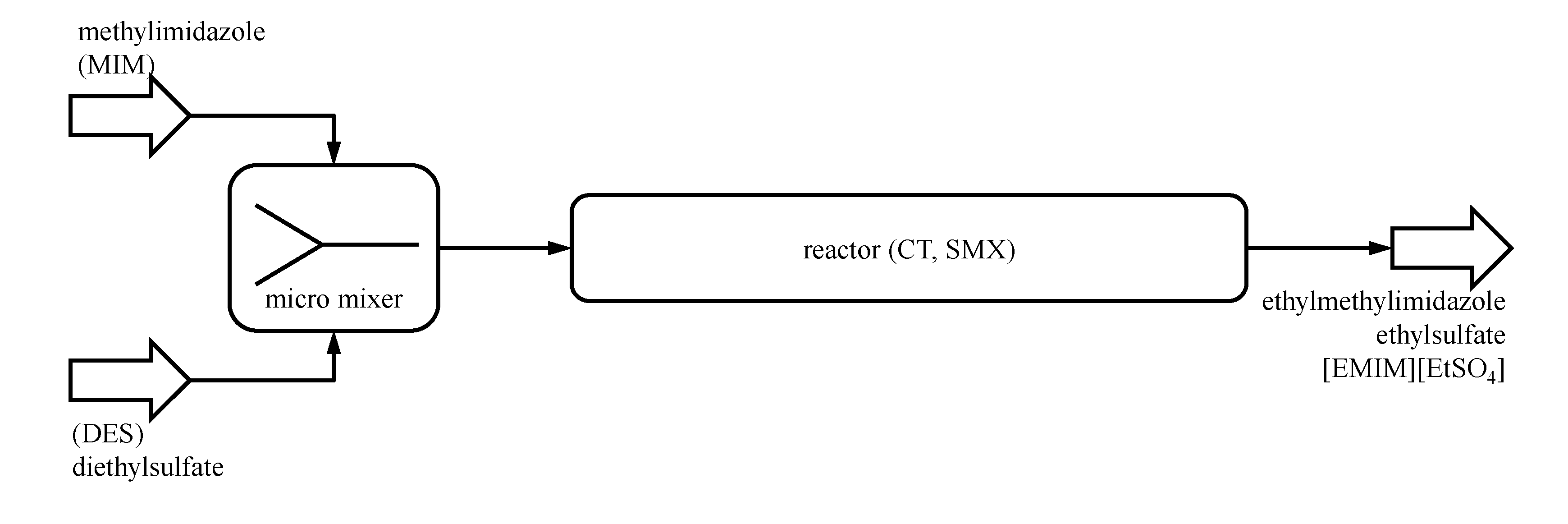
Five elements of each reactor system are assumed to be in stock and can be used for a fast construction of the reactor module. A flow micromixer will be implemented in any case, initially mixing the reactants before entering the CT or SMX reactor, as proposed by Renken
et al. [
29] for this reaction (
Figure 5). The residence time of the micromixer is assumed to be less than one second, so the reaction inside the micromixer will be neglected.
Table 2.
Simplified reactor database for coiled tube (CT) and static mixer reactors (SMX) (* assumption for demonstration purpose).
Table 2.
Simplified reactor database for coiled tube (CT) and static mixer reactors (SMX) (* assumption for demonstration purpose).
| data type | symbol | unit | CT3 | CT6 | CT8 | SMX8 | comments/source |
|---|
| geometries | da | mm | 3.0 | 6.0 | 8.0 | 8.0 | standard tubing |
| di | mm | 1.4 | 4.4 | 6.0 | 6.0 |
| s | mm | 0.8 | 0.8 | 1.0 | 1.0 |
| L0 | m | 4.75 | 4.75 | 4.75 | 1.50 | * |
| ε | - | 1.00 | 1.00 | 1.00 | 0.67 | only SMX [37] |
| Dcoil | mm | 100.0 | 100.0 | 100.0 | - | * |
| hcoil | mm | 6.0 | 12.0 | 16.0 | - | *,
hcoil = 2da |
| dh | mm | 1.4 | 4.4 | 6.0 | 1.5 | CT:
dh = di,
SMX: dh = 0,25 di [38] |
| Afree,0 | mm² | 1.54 | 15.2 | 28.3 | 18.9 | ![Processes 02 00265 i020]() |
| V0 | ml | 7.3 | 72.2 | 134.3 | 28.4 | V0 = Afree,0L0 |
| a | m2·m−3 | 2861 | 909 | 667 | 996 | a = πdiL0/V0 |
| allowed operation conditions | pmin | barg | −1 | −1 | −1 | −1 | * |
| pmax | barg | 670 | 310 | 310 | 310 | standard tubing |
| Tmin | °C | −20 | −20 | −20 | −20 | * |
| Tmax | °C | 200 | 200 | 200 | 200 | * |
| correlations | ζ(Re) | - | [39] | [38] | |
| Nu(Re,Pr) | - | [40] | [41] |
Figure 4.
Helically coiled tubular reactor (CT6).
Figure 4.
Helically coiled tubular reactor (CT6).
The process presettings and constraints (
Table 3) being provided by the conceptual process design and the laboratory development and the physical/chemical properties of the reacting system are taken from the literature [
28,
42,
43]. All physical properties of the reacting fluid were assumed to be constant at temperature
TR. Adequate assumptions (*,
Table 3) according to the actual operating conditions (throughput, temperature pressure) were made.
Figure 5.
Flowsheet of the example process plant: micromixer to initially mix the reactants; CT or SMX reactor for the main conversion.
Figure 5.
Flowsheet of the example process plant: micromixer to initially mix the reactants; CT or SMX reactor for the main conversion.
Table 3.
Presettings and constraints (* assumption for demonstration purpose).
Table 3.
Presettings and constraints (* assumption for demonstration purpose).
| symbol | unit | value | comments/source |
|---|
| ṁ | kg·h−1 | 0.30 | *, ~4.6 mL·min−1 |
| ±f | % | 5 | * |
| cMIN | mol·L−1 | 4.80 | [28] |
| cDES | mol·L−1 | 4.73 | [28] |
| TR | °C | 24 | *, adapted to experimental data [28] |
| Tmin | °C | −6 | crystallization of MIM [44] |
| Tmax | °C | 100 | undesired thermal decomposition of the IL [28] |
| pR | barg | 0 | * |
| τdesign | min | 38 | [28] |
| τmin | min | 30 | *, conversion too low below |
| τmax | min | → ∞ | *, high residence times needed to reach ambient conversion (second-order reaction), no long-term side/subsequent reactions known |
| Xdesign | % | →100 | * |
In order to calculate the heat transmission coefficients, contributions to external heat transfer were neglected for all reactor systems. The heat conductivity of the wall material was set to 15 W m−1·K−1, being adequate for high quality steel tubing.
Based on these data and assumptions, a complete pass through the reactor selection methodology and a simple by-hand optimization, utilizing the computer-aided execution of the reactor selection methodology, will be presented in the following.
4.2. Example: Step 2, Operating Pressure (Technical Criterion)
The low volumetric flow rate of 4.6 mL·min
−1 leads to low flow velocities and corresponding Reynolds numbers in the channels of the remaining reactor setup. Combined with a moderate dynamic viscosity of about 0.1 Pa·s of the reacting fluid [
42], the pressure drop in all remaining reactor setups is below 1 bar. Thus, safety issues due to high pressure or difficulties operating the reactor systems with standardized pumps of the MCSP reactor module are not expected here. All setups remain feasible according to this step.
The pressure drop in the
CT6 setups ranges from 12–218 mbar, corresponding to flow velocities of 1.0–5.0 mm·s
−1 and Reynolds numbers of 0.05–0.24. In the
CT8 setups, the pressure drop ranges from 4–64 mbar, corresponding to flow velocities of 0.5–2.7 mm·s
−1 and Reynolds numbers of 0.03–0.17. The pressure drop in the
SMX8 setups ranges from 27–683 mbar, corresponding to flow velocities of 0.8–4.0 mm·s
−1 and static mixer Reynolds numbers [
38] of 0.01–0.06.
4.3. Example: Step 3, Operating Temperatures (Technical Criterion)
The adiabatic temperature rise of the reaction is high, but the heat transfer abilities of all remaining reactor setups appear to be sufficient to remove the heat of the reaction according to the simplified black-box model (Equation (7)). All reactor systems provide high specific surface areas and can, therefore, achieve ambient heat transfer rates, although the flow regime in the channels is laminar, and the resulting heat transfer coefficients appear quiet low. Comparing all setups using five elements, the setups (1,5) show superior heat transfer abilities over the respective setup (5,1), due to the higher flow velocity/Reynolds number and resulting heat transfer coefficient in the single channel setup. This results in a lower necessary characteristic temperature difference to the HTF for the setup (1,5) compared to setup (5,1) (
Table 7).
Table 7.
Heat transfer area, heat transmission coefficients and characteristic temperature differences to the heat transfer fluid (HTF) for the selected setups.
Table 7.
Heat transfer area, heat transmission coefficients and characteristic temperature differences to the heat transfer fluid (HTF) for the selected setups.
| Symbol | value | CT6 (1,5) | CT6 (5,1) | CT8 (1,5) | CT8 (5,1) | SMX8 (1,5) | SMX8 (5,1) |
|---|
| aiV | m2 | 0.33 | 0.45 | 0.14 |
| kh | W·m−2·K−1 | 168 | 158 | 121 | 115 | 363 | 364 |
| ΔTHTM | K | 0.8 | 3.5 | 0.7 | 3.5 | 0.7 | 4.8 |
In the case of a process development project, where a mathematical description of the reaction kinetics is not available in the early state of the project, the setups CT6 (1,5), CT8 (1,5) and SMX8 (1,5) are most promising for the temperature sensitive IL synthesis reaction, due to their superior heat transfer abilities and high residence time compared to other setups and because of their technical feasibility compared to the CT3 reactor system (Chapter 4.1). Thus, experimental validation should focus on these preselected reactor systems.
4.4. Example: Step 4, Kinetics of Mixing and Reaction (Technical Criterion)
The IL synthesis reaction was characterized as a Type B/C reaction (see chapter 4.) due to the characteristic timescale of the reaction. Thus, the reaction progress will be dominated by the intrinsic reaction kinetics. Assuming sufficient initial mixing of the reactants by use of the micromixer connected upstream of the residence time channels (
Figure 5), mixing in the reactors needs not to be investigated in more detail and is therefore neglected here.
4.6. Optimization Study
Although the most promising setups were identified by the first run of the reactor selection methodology, the attained results are not satisfying. Both setups reach [EMIM][EtSO4] yields of less than 90%. Therefore, more than 10% of the unreacted educts leave the reactors.
Behind the hotspot, the reaction rate (slope of the yield profile) significantly decreases, due to the strong concentration dependence of the second order reaction, and a high additional residence time is needed to further increase the conversion and yield. Three elements of the
SMX8 (
τSMX8 = 19 min) are sufficient to reach a yield of 63% and to bring the temperature of the reacting fluid closely back to
TR. The outlet conditions of
SMX8 (1,3) can be used now for a second run of the reactor selection methodology at elevated temperature
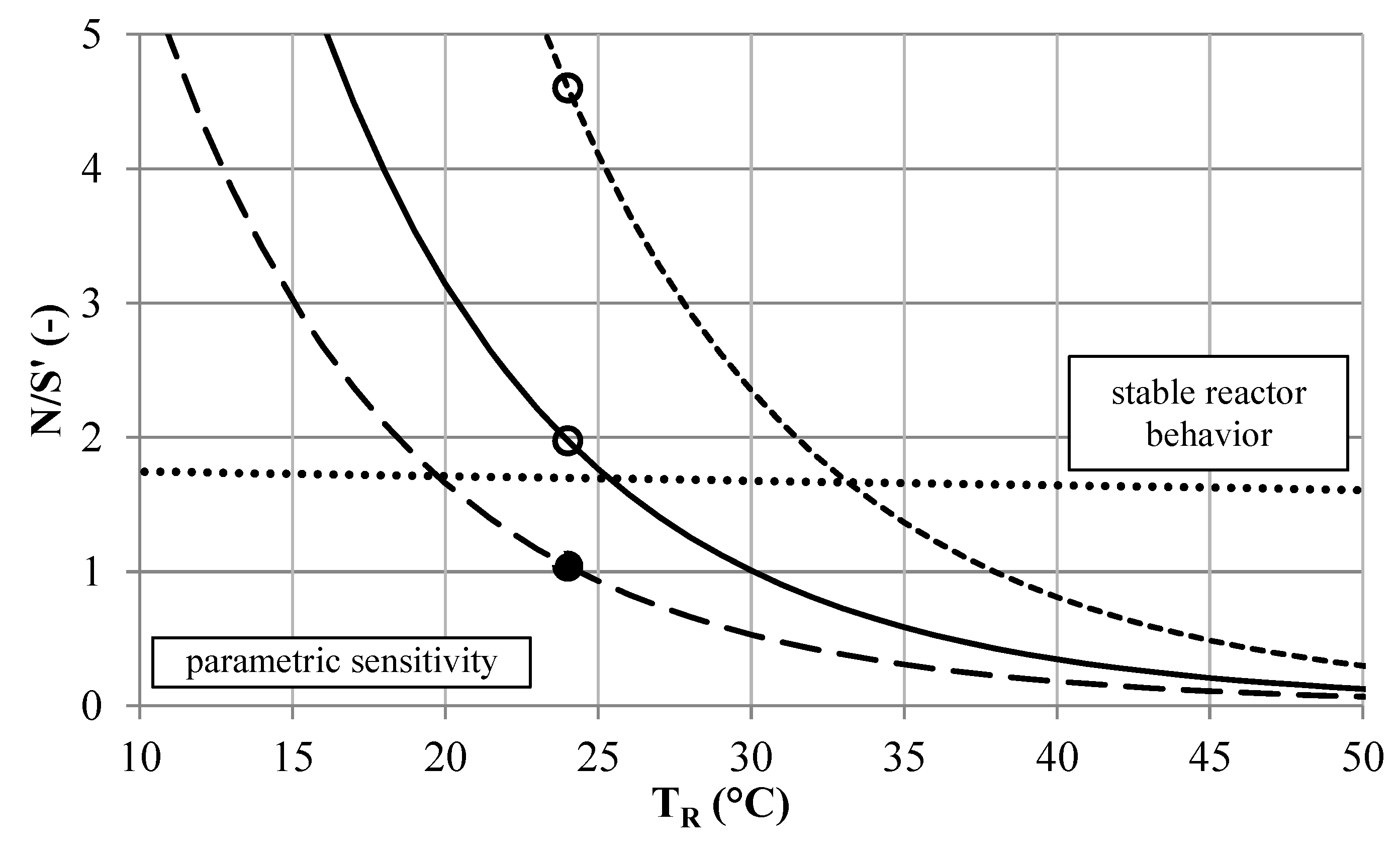
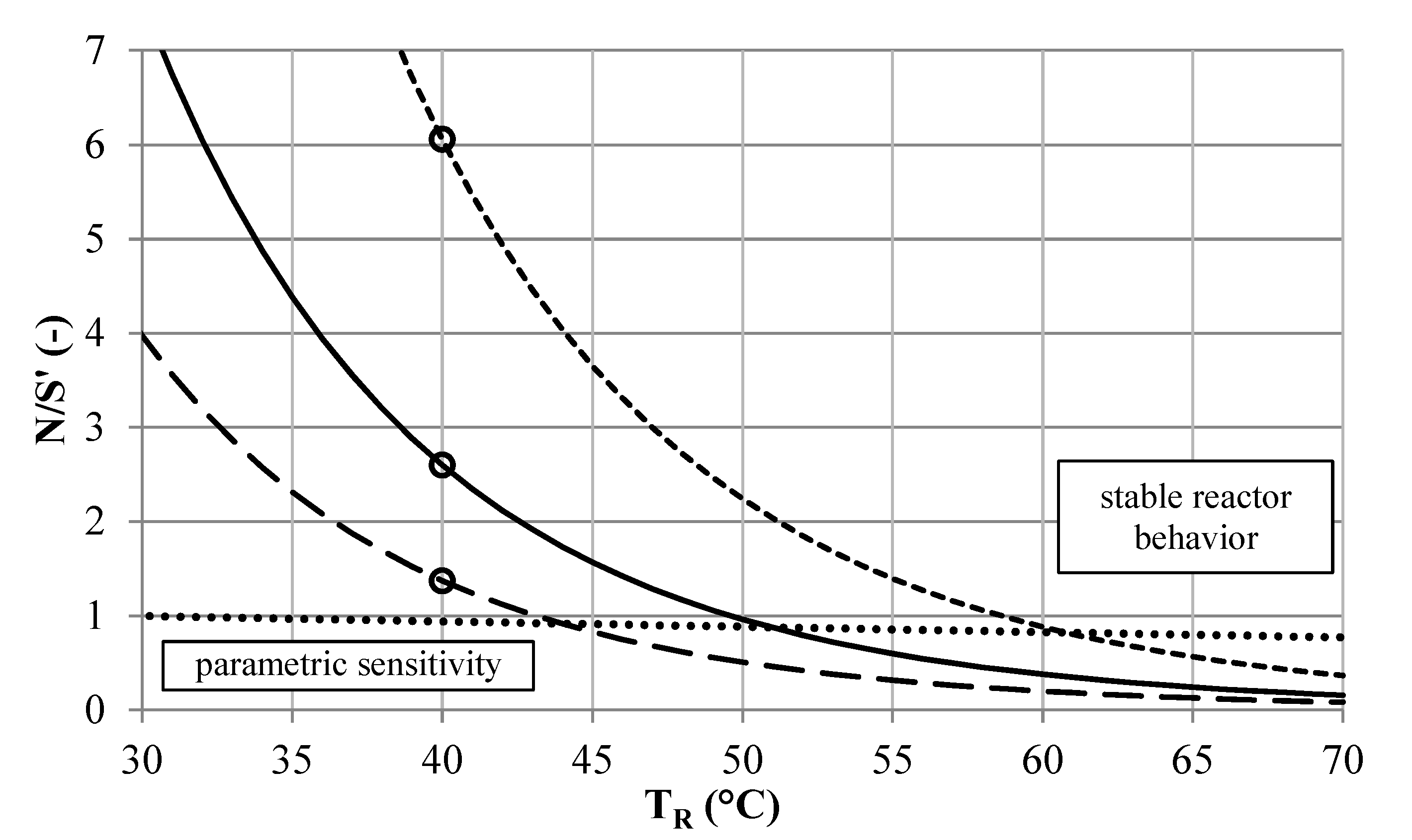
TR to again an increase in the reaction rate. A stability analysis for the changed inlet conditions (
Figure 8) assists the choosing of the reaction temperature of
TR = 40 °C.
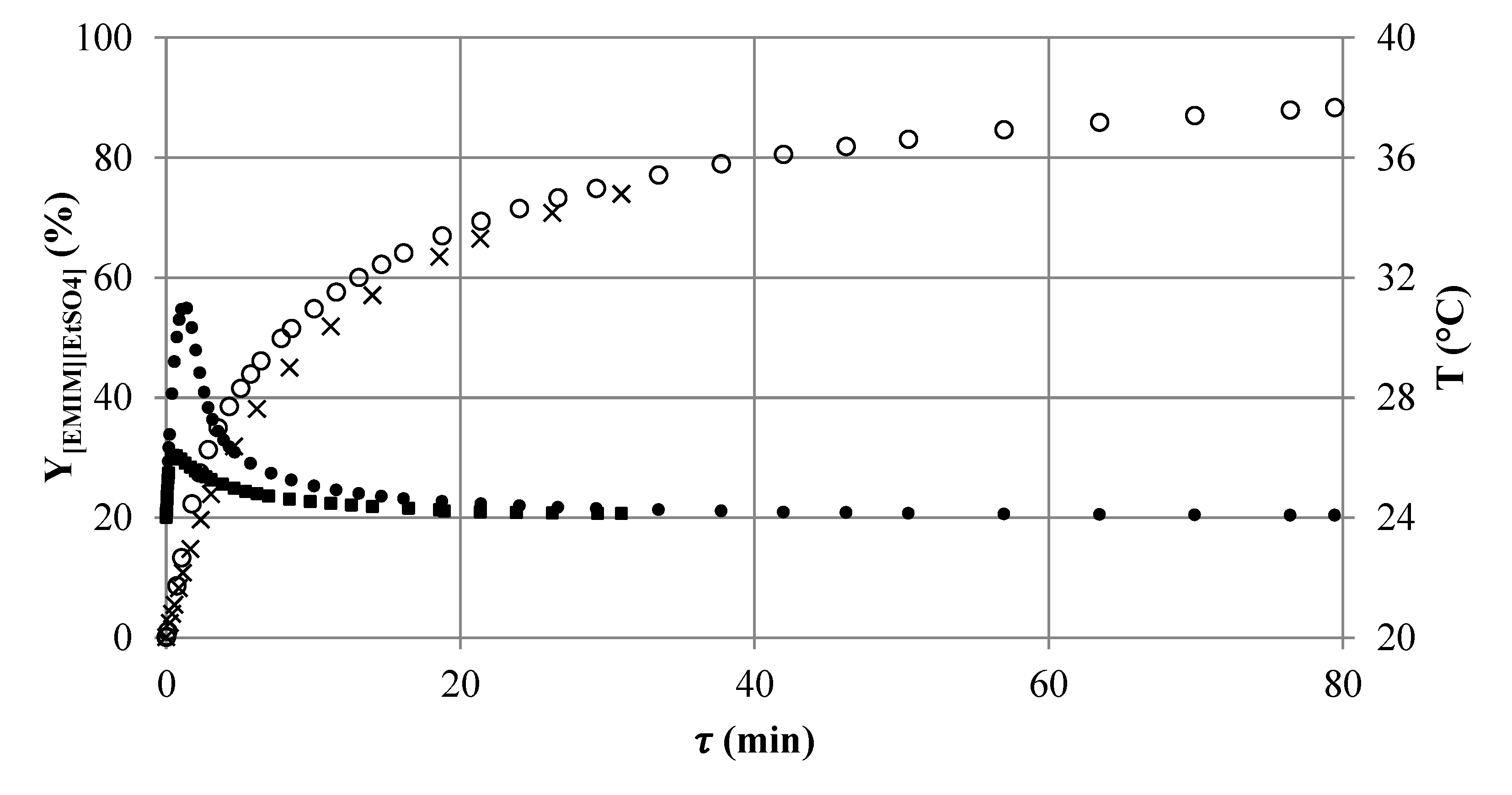
Figure 8.
Stability analysis of the [EMIM][EtSO
4] synthesis according to the BR approach. Unstable operation (•) and stable operation (∘) at
TR = 40 °C and initial conversion of 63.4%, for reactor setups
CT6 (
![Processes 02 00265 i021]()
),
CT8 (
![Processes 02 00265 i022]()
) and
SMX8 (
![Processes 02 00265 i002]()
) and BR stability (····).
According to the second run of the reactor selection methodology, a
CT8 (1,2) setup is sufficient to reach a conversion of about 98% when being placed downstream of the
SMX8 (1,3) setup (
Figure 9). The use of compact
CT reactors might be favored over using straight tube
SMX reactors in the MCSP environment, considering the space demand of the systems.
Figure 9.
Simulated axial yield profile of [EMIM][EtSO4] in reactor setup SMX8 (1,3) (×) followed by CT8 (1,2) (∘) connected in series and the corresponding temperature profile in the reactor setup SMX (1,3) (■) (TR = 24 °C) followed by CT8 (1,2) (•) (TR = 40 °C).
Figure 9.
Simulated axial yield profile of [EMIM][EtSO4] in reactor setup SMX8 (1,3) (×) followed by CT8 (1,2) (∘) connected in series and the corresponding temperature profile in the reactor setup SMX (1,3) (■) (TR = 24 °C) followed by CT8 (1,2) (•) (TR = 40 °C).
4.7. Conclusion to the Example
The presented reactor selection methodology provides a fast (short-cut) approach to quantitatively identify promising reactor concepts based on predefined available reactor systems in the early stages of process development. Remarkably, two of three reactor configurations that are most promising after Step 3 (low demand of data) remain favored after the whole procedure. Depending on the currently available data, the most promising setups after any step of the methodology can be preferentially used for experimental analysis, validation and/or optimization. Therefore, the reactor selection methodology contributes to the effective guiding and planning of the laboratory development and to the fastening of the whole process development of the MCSP processes. Furthermore, the model equations of the reactor selection methodology clearly define the demand of the data needed for an early start-up of the process development. Thus, missing information can be gained systematically.
By computer-aided execution of the methodology, even a large number of different reactor systems/configurations can be screened in few minutes of computing. Therefore, a simple optimization study of the promising reactor systems can be carried out, resulting in a technically suitable setup. This setup will not be optimal by means of mathematical optimization, but might be technically sufficient, if a fast “time-to-process” and the use of predefined equipment is the key issue.
Alternatively, the results gained by the reactor selection methodology can be used as initial values/benchmark for more detailed mathematical optimization considering, e.g., multi-injection concepts [
30] or, as mentioned before, for a systematical experimental validation.
5. Conclusions and Outlook
The modular approach of MCSP offers an opportunity for the quick realization and flexible design of future production plants. One key aspect is to establish a concept for the reuse of process and engineering knowledge throughout the process development chain and adjacent projects. The definition of reusable basic modules and associated documentation packages simplifies engineering and saves time during the construction phase. By using already tested and validated designs for the peripheral devices, as well as the predefined main apparatus, quick implementation in a production environment can be reached.
The scale-up of continuous processes into an MCSP requires a detailed calculation of all relevant physical and technical phenomena. This calculation process is significantly simplified using the presented computer-aided methodology for homogeneous liquid phase reactions and reactor systems. It allows fast and quantitative generation and rating of process alternatives based on predefined apparatuses. Once the needed process data are obtained, the generation of results can be realized within a few minutes. This is enabled by a database of quantitative calculation methods for each available apparatus, preserving the knowledge between different projects. Through a five-step selection methodology, all infeasible apparatuses are rejected from the selection process, if technical process requirements cannot be fulfilled. The remaining reactor setups are characterized by several performance indicators to assist the further selection process. The stepwise calculation method can be used in the early process development phase, even if the necessary process dataset is incomplete.
Furthermore, the utilization of the tool already in laboratory development phase can help to identify critical scale-up parameters and essential lab data. The importance of each calculation step strongly depends on the dominating physical phenomena within the specific process. Based on datasets for equipment of different production capacities (lab, pilot, production) and different dominating phenomena (mixing intensity, heat transfer, residence time), suitable devices for lab investigations can be easily identified. This can lead to an effective planning and guiding of scale-up experiments and closes the usual gaps between lab and process development. After the successful selection of a preferred main apparatus and its configuration, the modular design of the MCSP enables the easy integration of the predefined equipment.
So far, the reactor selection tool only enables the selection of a reactor for one desired operation point. To further strengthen the methodology, an automated flexibility assessment for the equipment is developed to evaluate multiple possible operation points. By now, this can be archived via manual parameter variation (sensitivity analysis). Furthermore, detailed data (heat transfer, back mixing and pressure drop) are needed to quantify and reliably predict the performance, especially of process-intensified milli- or micro-structured equipment.
The presented computer-aided methodology is currently utilized to optimize existing and new MCSP processes for continuous operation at the INVITE research center in Leverkusen, Germany. Operational experience and measurement data from the investigated devices will be used to validate the database content. Further steps are to implement multiphase systems into the methodology and to elaborate a similar approach for downstream unit operations.


 CT6(np, ns)
 ), CT8 (
  ) and SMX8 (
  ) and BR stability (····).


