Article

A Novel Cell Seeding Chamber for Tissue Engineering and Regenerative Medicine

1
Fluid Technology and Microfluidics, University of Rostock, Rostock 18055, Germany
2
Laboratory for Experimental Surgery and Regenerative Medicine, Department of Surgery, University of Munich, Munich 80539, Germany
*
Author to whom correspondence should be addressed.
Processes 2014, 2(2), 361-370; https://doi.org/10.3390/pr2020361
Submission received: 14 February 2014 / Revised: 11 April 2014 / Accepted: 18 April 2014 / Published: 30 April 2014
(This article belongs to the Special Issue Design of Bioreactor Systems for Tissue Engineering)

Abstract

:
There is an increasing demand for bone graft substitutes that are used as osteoconductive scaffolds in the treatment of bone defects and fractures. Achieving optimal bone regeneration requires initial cell seeding of the scaffolds prior to implantation. In order to achieve an efficient seeding of the scaffolds, a novel cell seeding chamber was developed. The cell seeding chamber is a closed assembly that works like an hourglass. The position of the scaffold is between two reservoirs containing the cell suspension (e.g., blood or autologous bone marrow). The cell suspension at the upper reservoir flows through the scaffold by gravitational force. The cell suspension is collected at the lower reservoir. When the upper reservoir is empty the whole assembly is turned and the process starts again. In this study, a new compact cell seeding chamber for initial cell seeding has been developed that can be used in situ. The basic functionality of the cell seeding chamber was demonstrated with a blood substitute.

1. Introduction

In spite of the high healing potential of the human body, a permanent loss of bone tissue is still an unsolved complex clinical problem [1,2]. Especially in elder people, critical size bone defects are common pathologies. The implantation of autologous bone tissue is currently the “golden standard” [3]. However, in more than 40% of these cases, autologous bone graft is not available [1]. Another disadvantage in using autologous bone grafts is the additional surgery which is necessary to extract the implant. However, there are other therapeutic approaches such as the use of allogenic, xenogenic or synthetic bone graft substitutes. Unfortunately, the healing behavior of these structures is insufficient. To improve the healing behavior of bone graft substitutes the scaffolds are vitalized with autologous cells which can be obtained, for example, from blood or from bone marrow [4].
There are microchip-based bioreactor systems that can organize cells into adherent multicellular aggregates [5,6]. There are also several systems that can vitalize non-living scaffolds [7,8,9,10,11]. Most of the systems however, are for research and for laboratory applications but there are also systems that can be used in situ, i.e., the operating theatre. Systems for lab use are usually very complex and risk of contamination of the scaffolds is always possible. This is the reason why these systems cannot be used in the operating theatre. Therefore, these kinds of bioreactors are only used for research in the field of tissue engineering applications. The advantages of these systems however, are the continuous medium flow through the scaffolds, an optimized nutrient supply of the cells as well as the removal of metabolism products. There have been developments to increase the mass transfer of cellular scaffolds not only at the periphery but also within the interior of scaffolds, increasing cellular proliferation, and osteogenic differentiation by perfusion bioreactors [12]. The scaffold is usually fixated in a little chamber and the cell suspension flows continuously through the scaffold. The cell suspension flow is usually generated by a pump [7], hydrostatic pressure or centrifugal forces [10,11].
The cell seeding chamber “chronOS Perfusion Concept” (Synthes Inc., West Chester, PA, USA) is a system which is applicable in the operating theatre. It is used by manually wetting the scaffold with a cell suspension (e.g., blood or bone marrow). The cell suspension is squeezed through the scaffold by consecutively moving the piston of a fixated syringe. However, the disadvantage is that it does not guarantee a continuous flow of the cell suspension and is susceptible to human error.
This newly developed cell seeding chamber combines the advantages of both, laboratory and surgical systems. The system fulfills the main requirements for a feasible in situ cell seeding chamber by realizing a continuous and steady volume flow as well as a relatively easy setup and portability. The cell seeding chamber is a closed assembly with complete integrated functionality.

2. Materials and Methods

2.1. Cell Seeding Function

In order to build a feasible cell seeding chamber, a number of requirements need to be met. The cell seeding chamber should continuously infiltrate the scaffold with a steady flow. The goal is to abstract around 15 mL of blood from a patient and insert it into the cell seeding chamber.
The specifically designed chamber insures a continuous flow through the scaffold, so it can be initially seeded with cells. The cell suspension flow is driven by gravity. A volume of 15 mL will flow through the scaffold in a range of 5 min. By turning the chamber 180° the process restarts, resulting to a closed loop system.
The cell seeding chamber is depicted in Figure 1. It consists of a closed chamber (1). Inside the chamber there are two reservoirs (2). The cell suspension flow is adjusted by the dimensions of the reservoir (diameter/height) and the outflow channel (3). The cell suspension flows through the openings (4) and is collected in the lower reservoir. The scaffold is fixed between these two reservoirs (5). The cell suspension is provided in one of these reservoirs. The whole assembly will be positioned in a way that the reservoir containing the cell suspension is on top of the fixed scaffold (6). The cell suspension flows out of the reservoir, driven by gravity. The cell suspension drips on the fixed scaffold and flows through the scaffold. The cells in the cell suspension adhere to the surface of the scaffold during this process. At the time when the upper reservoir is empty and the whole cell suspension is collected in the lower reservoir the cell seeding chamber (1) is turned manually by 180° and the process restarts. The cell suspension is injected via syringe through a septum (7).
Figure 1. Schematic presentation of the newly developed cell seeding chamber.
Processes 02 00361 g001

2.2. Blood Substitute

A typical cell suspension (e.g., blood or bone marrow) is a non-Newtonian fluid. For the experiments, a blood substitute was used. Non-Newtonian blood substitutes are often based on polymer solutions, for example mixtures of water and glycerin or mixtures of water, glycerin and xathan. Sometimes solutions of polyacrylamide are used [13,14,15]. The viscosity of the blood substitute was measured and adjusted in relation to the flow rate in the cell seeding chamber. The basic functionality of the cell seeding chamber was tested with a solution of water and xanthan (0.05 wt%) [15]. Viscosity of the blood substitute was checked with the rheometer Mars 2 (Haake, Thermo Fisher Scientific Inc., Waltham, MA, USA), resulting in properties close to blood.

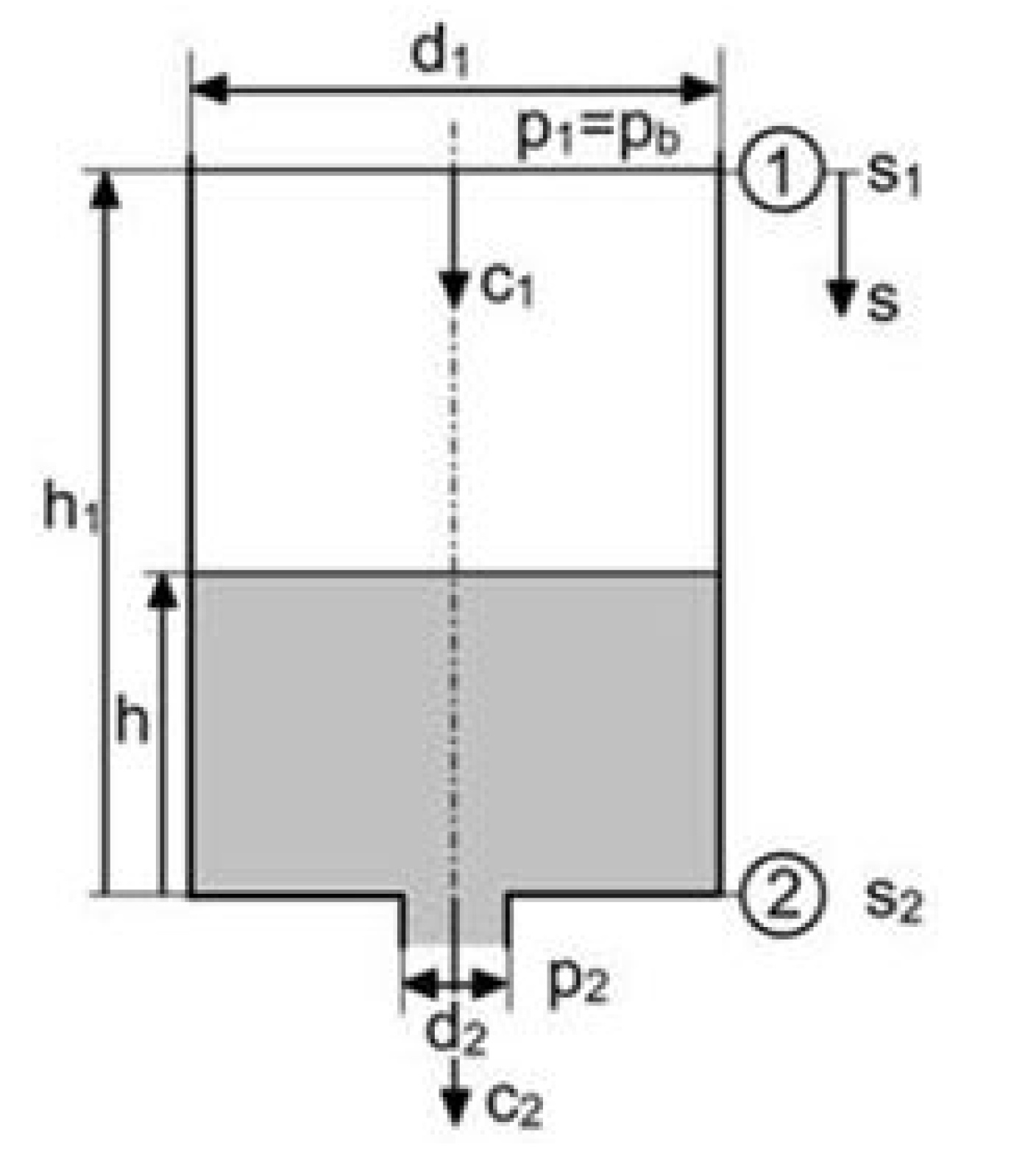
2.3. Analytical Approach of the Cell Suspension Flow

The cell suspension flow out of the upper reservoir can be divided into three sections.
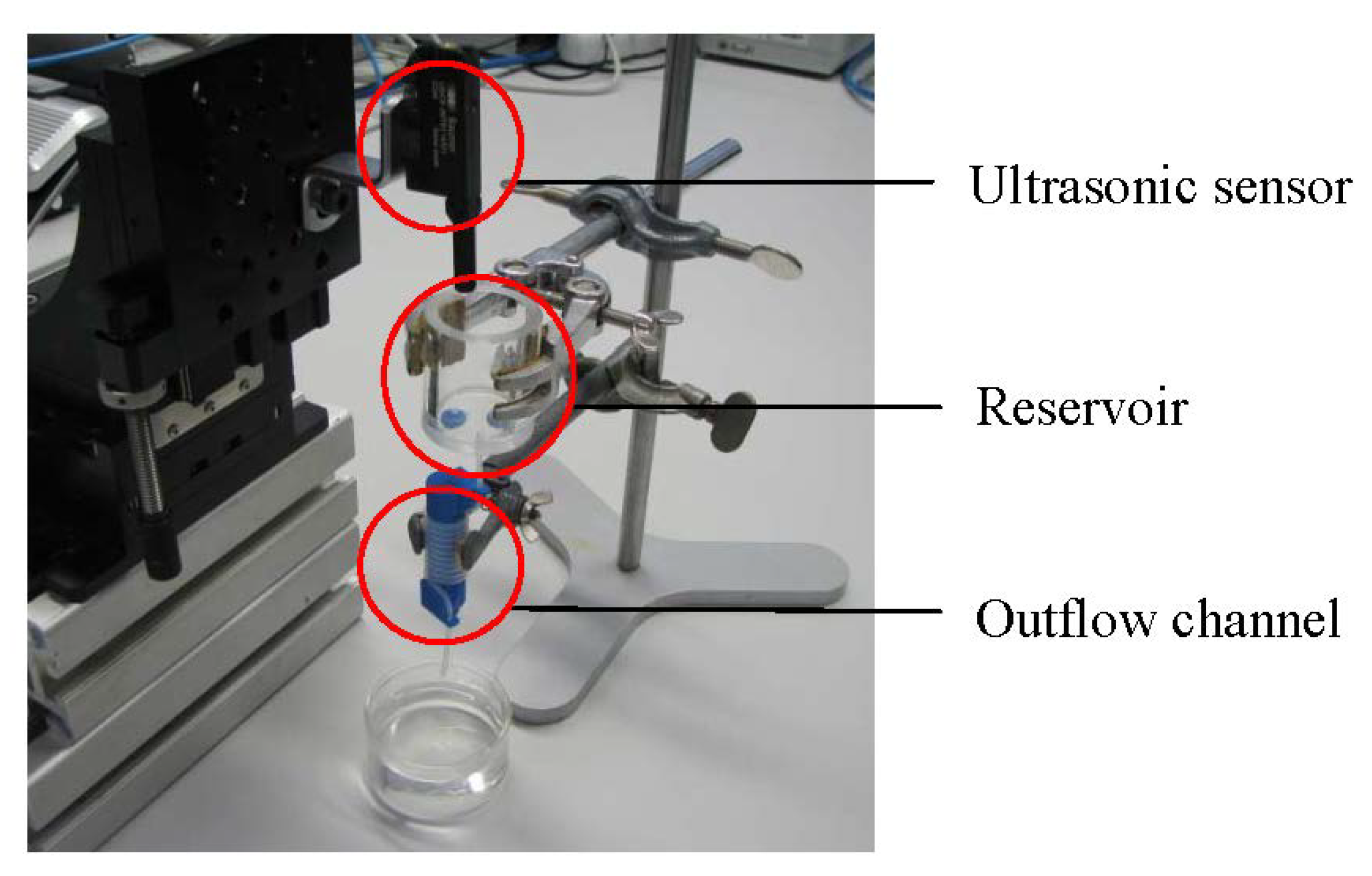
  • At first a cell suspension flows out of a reservoir with a variable cell suspension level (h(t));
  • The second section is a cell suspension flow through the outflow channel;
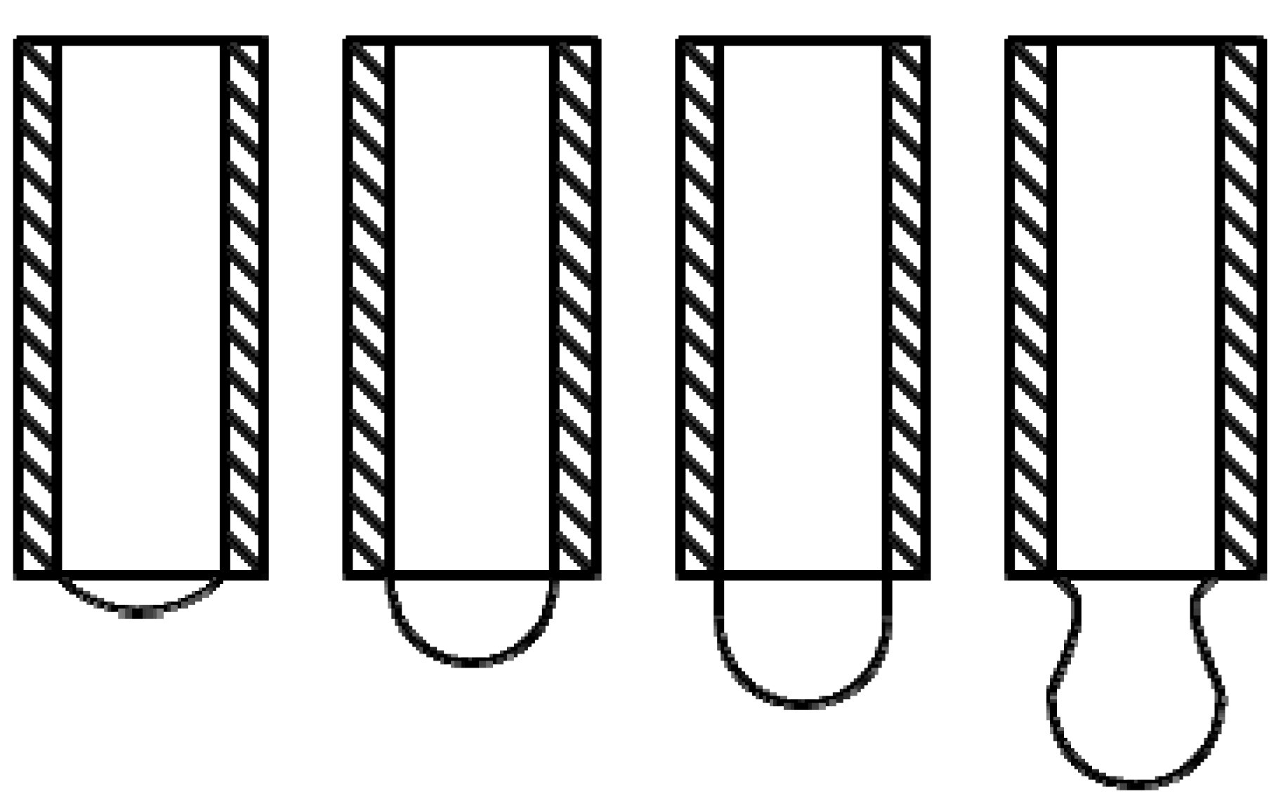
  • At last there is a drop formation at the end of the outflow channel;
In terms of the Bernoulli equation [16],
Processes 02 00361 i001
The pressure difference which is necessary for the cell suspension to flow is mainly generated by the hydrostatic pressure. Therefore, the length (l) and inner diameter (di) of the second section are the significant parameters. The cross section of the outflow channel (AA) is much smaller than cross section of the reservoir (AB), so there is an increased flow velocity in the outflow channel, as depicted in Figure 2. The flow velocities c1 and c2 of the continuity equation can be converted into one another.
Figure 2. Reservoir for cell suspension [16].
Processes 02 00361 g002
Excluding the outflow channel and the droplet at the end of the outflow channel, the simplified Bernoulli equation like [16]:
Processes 02 00361 i002
The hydrostatic pressure in the reservoir depends only on the overall height (h), the density (ρ) and gravitational forces (g). The volume flow is the result of the cell suspension level at the container (h(t)) and the length of the outflow channel (HW), as seen in Equation (3).
h = h(t) + HW
The volume flow is dependent on hydrostatic pressure and frictional forces. The outflow channel has a drag that works against the volume flow and increases by increasing flow velocities. In order to achieve very little changes in the hydrostatic pressure, the height of the reservoir should change as little as possible. Therefore, the cross section of the reservoir (AB) should be as big as possible so the cell suspension level variation during time (h(t)) is low leading to a minor deviation in the flow rate. The first prototype was designed to have a large reservoir with a very small tube diameter of the outflow channel in order to decrease the influence of the hydrostatic pressure.
However, empirical studies have shown that a very small inner diameter of the outflow channel was not beneficial to the sequence of the cell suspension flow. Due to the fact that blood or other cell suspensions behave like a non-Newtonian fluid and that there is only a small pressure difference, the capillary forces are not strong enough to support a steady flow of the cell suspension. Therefore, a spiral tube with a bigger inner diameter was implemented leading to a relatively even flow rate. The approach was to design the spiral hose in accordance to the parameters calculated from Equation (4) [17].
Processes 02 00361 i003
where λ is the pipe friction coefficient, dhyd the hydraulic diameter of the outflow channel and cm the median flow velocity. The length and the diameter of the outflow channel were chosen, so that the pressure difference and the volume flow are similar to the theoretical values of a straight outflow channel. Figure 3 shows the result of the design. The length l of the hose is approximately 500 mm and the diameter Dw of the winding is 8.5 mm with a vertical inlet and outlet.
Figure 3. Outflow channel.
Processes 02 00361 g003
The new design insures a steady flow of the cell suspension without the problem of blockage. However, the outflow of the cell suspension cannot be determined analytically, due to the complexity of drop formation at the end of the outflow channel. Figure 4 shows the stages of the drop formation. Therefore, an empirical approach has been chosen.
Figure 4. Stages of drop formation.
Processes 02 00361 g004

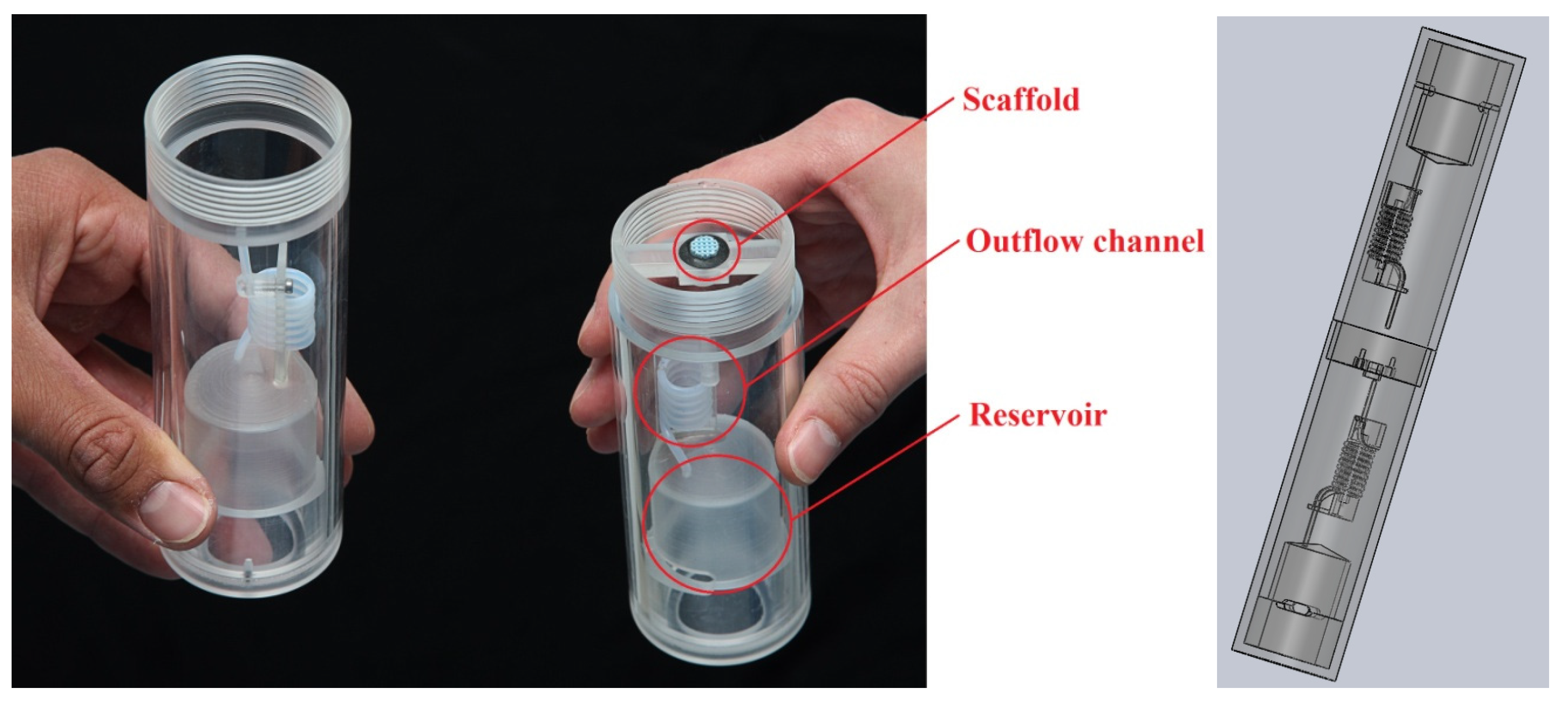
2.4. Cell Seeding Chamber Design

The cell seeding chamber is made of polymethyl methacrylate (PMMA) and polytetrafluoroethylene (PTFE) for the outflow channel and has been tested successfully for sterilization by autoclave. The outflow channel is formed like a spiral to insure a compact design with the required length, as seen in Figure 5. The cell suspension reservoirs have a diameter of 30 mm and are located on both ends of the chamber and can hold the desired 15 mL. A disc shaped scaffold is fixated in the middle of the cell seeding chamber by a small pot with a diameter of 10 mm. The cell seeding chamber was tested with two different inner diameters of the outflow channel, resulting in different outflow times. Different scaffold sizes and shapes have yet to be used to investigate possible variations in fluid behavior and cell distribution.
Figure 5. New design of the cell seeding chamber.
Processes 02 00361 g005

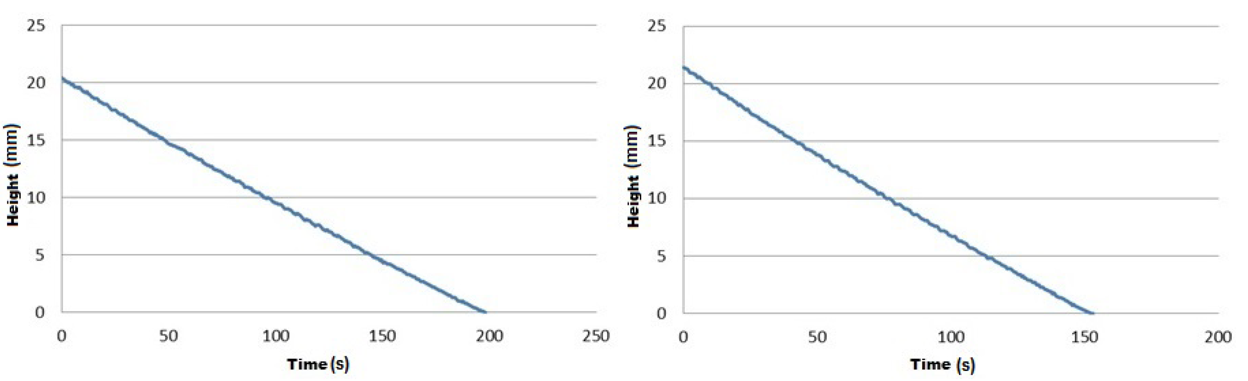
2.5. Media Flow Rate of the Reservoir

The outflow channel is completely filled with the blood substitute and closed at the lower end. Subsequently, 15 mL of blood analogue is filled in the reservoir and the flow has been measured at least five times. The reservoir and outflow channel were cleaned and dried after each test, to ensure the repeatability of the test. The measurement starts at the moment in which the lower end of the outflow channel is opened, and stops when the reservoir is completely empty.
The liquid level in the reservoir was measured over time with an ultrasonic sensor UNCK09 (Baumer GmbH, Friedberg, Germany), as shown in Figure 6. The ultrasonic sensor has a measuring range of 3 to 150 mm and is suitable for transparent media. The recorded height is transmitted via a COM port on a computer and evaluated using Labview (National Instruments Germany GmbH, Munich, Germany). Values were detected with a time interval of 0.46 s.
Figure 6. Sensor based analysis of flow rate—outflow channel.
Processes 02 00361 g006

3. Results

Cell Suspension Flow Rate

The time for the cell suspension to flow through the outflow channel has been measured. Two outflow channels with different inner diameters were investigated. The outflow channel with an inner diameter of 1.5 mm and 1.6 mm resulted in an outflow time of 200.2 s and 153.8 s, respectively. The representation of the change in the level height in the reservoir over time shows an approximately linear behavior, as seen in Figure 7. This leads to a relatively steady flow of the cell suspension in the cell seeding chamber. For comparison the outflow from a reservoir without an outflow channel is exponential as shown by Torricelli’s law. This is not desirable, because a steady volume flow is vital to a functional cell seeding chamber. There is still a certain gradient between the beginning and the end of the flow process in the new system. However, due to the little height change in the reservoir height, the hydrostatic pressure has little effect on the flow rate. Additionally, higher flow rates lead to an increase of friction, which has a compensating effect on fluctuations of the flow rate.
The reservoir, with an inner diameter of 30 mm, is filled with 15 mL of the blood substitute. This results in a fluid level of 21 mm. The outflow channel has, including the vertical inlet and outlet section, an overall height of 90 mm. Adding up the initial filling level with the height of the outflow channel, a hydrostatic pressure of 1191 Pa was calculated in regard to a Newtonian cell suspension with a density of 1095 kg/m3. The calculated hydrostatic pressure for the case of an empty reservoir is 967 Pa, leading to a pressure difference of 224 Pa or rather a percentage difference of 19%. The measurements of the outflow channel with an inner diameter of 1.5 mm and 1.6 mm lead to a volume flow of 4.3 mL/min and 6.5 mL/min, respectively. Additionally, there is a formation of drop at the end of the outflow channel, which breaks off after exceeding the balance of weight and surface force. The drop formation is a complex process due to its various phases, as seen in Figure 4. At the lower end of the outflow channel the droplet is initially in form of a meniscus, it will eventually grow to a hemisphere, and then pass over represented in the typical form of drops.
Figure 7. Outflow experiments with an attached outflow channel, tube inner diameter 1.5 mm (left) and tube inner diameter 1.6 mm (right).
Processes 02 00361 g007
The experimental setup has shown that the newly developed cell seeding chamber resulted in a relatively steady flow rate. However there are still complex processes within the outflow process that need to be investigated further. Additionally, there are biological criteria that need to be addressed in future studies. A recent study has shown that oxygen tension and feeding regime (glucose, amino acids, etc.) are the two most important parameters in operating bioreactors [18]. Furthermore, the effects of fluid velocity, seeding time and scaffold properties in regard to cell attachment and proliferation need to be investigated further.

4. Conclusions

The experimental analysis has demonstrated that a relatively big inner diameter of the outflow channel is necessary for proper functionality in comparison to a small and short outflow channel. To generate the necessary flow resistance, the length of the channel had to be enlarged. As an in situ application there is a requirement for compact assembly. This is the reason why the outflow channel was formed like a spiral. By using the acquired knowledge, a feasible design of the cell seeding chamber was determined and manufactured, as seen in Figure 5.
The basic functionality of the cell seeding chamber could be demonstrated with a blood substitute. The flow rate of the blood substitute could be adjusted in the range of 4.3 mL/min and 6.5 mL/min, leading to a continuous infiltration of the scaffold for approximately 3.5 and 2.5 min, respectively. The goal to achieve a steady flow for 5 min has almost been reached and further experiments should lead to the desired outflow time. However, further investigations need to be carried out in order to proof the full functionality of the system with real blood. The advantage generated by the cell seeding chamber in relation to established methods have to be verified by biological experiments. If a higher cell seeding efficiency can be verified, in particular in the middle of the scaffold, there is a basis for an animal trial that can demonstrate the healing behavior of a scaffold vitalized by the cell seeding chamber.

Conflicts of Interest

The authors declare no conflict of interest.

References

  1. Schneider, R.K.; Neuss, S.; Knüchel, R.; Perez-Bouza, A. Mesenchymale Stammzellen für das “tissue engineering” des Knochens. Der Phathol. 2010, 31, 138–146. [Google Scholar]
  2. Poander, S. In-vitro- und In-vivo-Untersuchungen zur Biofunktionalisierung von Knochenersatzmaterialien. Dissertation, Friedrich-Alexander-Universität Erlangen-Nürnberg, Erlangen, Germany, 2009. [Google Scholar]
  3. Linhart, W.; Briem, D. Knochenersatz 2000 bis 2010. Der Orthop. 2001, 30, 189–192. [Google Scholar] [CrossRef]
  4. Drosse, I.; Volkmer, E.; Capanna, R.; de Biase, P.; Mutschler, W.; Schieker, M. Tissue engineering for bone defect healing: An update on a multi-component approach. Injury 2008, 39, 9–20. [Google Scholar] [CrossRef]
  5. Altmann, B.; Löchner, A.; Swain, M.; Kohal, R.J.; Giselbrecht, S.; Gottwald, E.; Steinberg, T.; Tomakidi, P. Differences in morphogenesis of 3D cultured primary human osteoblasts under static and microfluidic growth conditions. Biomaterials 2014, 35, 3208–3219. [Google Scholar] [CrossRef]
  6. Ordovás, L.; Park, Y.; Verfaillie, C.M. Stem cells and liver engineering. Biotechnol. Adv. 2013, 31, 1094–1107. [Google Scholar] [CrossRef]
  7. Minuth, W.W.; Sittinger, M.; Kloth, S. Tissue engineering: Generation of differentiated artificial tissues for biomedical applications. Cell Tissue Res. 1998, 291, 1–11. [Google Scholar] [CrossRef]
  8. Sodian, R.; Lemke, T.; Fritsche, C.; Hoerstrup, S.P.; Fu, P.; Potapov, E.V.; Hausmann, H.; Hetzer, R. Tissue-Engineering Bioreactors: A New Combined Cell-Seeding and Perfusion System for Vascular Tissue Engineering. Tissue Eng. 2002, 8, 863–870. [Google Scholar] [CrossRef]
  9. Martin, I.; Wendt, D.; Heberer, M. The role of bioreactors in tissue engineering. Trends Biotechnol. 2004, 22, 80–86. [Google Scholar] [CrossRef]
  10. Martin, Y.; Vermette, P. Bioreactors for tissue mass culture: Design, characterization, and recent advances. Biomaterials 2005, 26, 7481–7503. [Google Scholar]
  11. Partap, S.; Plunkett, N.A.; O’Brien, F.J. Bioreactors in tissue engineering. In Tissue Engineering; Eberli, D., Ed.; InTech: Dublin, Ireland, 2010; pp. 323–336. [Google Scholar]
  12. Gardel, L.S.; Serra, L.A.; Reis, R.L.; Gomes, M.E. Use of Perfusion Bioreactors and Large Animal Models for Long Bone Tissue Engineering. Tissue Eng. Part B Rev. 2014. [Google Scholar] [CrossRef]
  13. Gray, J.D.; Owen, I.; Escudier, M.P. Dynamic scaling of unsteady shear-thinning non-Newtonian cell suspension. Exp. Fluids 2007, 43, 535–546. [Google Scholar] [CrossRef]
  14. Shibeshi, S.S.; Collins, W.E. The rheology of blood flow in a branched arterial system. Appl. Rheol. 2005, 15, 398–405. [Google Scholar]
  15. Sousa, P.C.; Pinho, F.T.; Oliveira, M.S.; Alves, M.A. Extensional flow of blood analog solutions in microcell suspensionic devices. Biomicrofluidics 2011. [Google Scholar] [CrossRef] [Green Version]
  16. Surek, D.; Stempin, S. Angewandte Strömungsmechanik; Teubner Verlag: Wiesbaden, Germany, 2007. [Google Scholar]
  17. Wagner, W. Strömung und Druckverlust; Vogel: Würzburg, Germany, 2001. [Google Scholar]
  18. Sart, S.; Agathos, S.N.; Li, Y. Process engineering of stem cell metabolism for large scale expansion and differentiation in bioreactors. Biochem. Eng. J. 2014, 84, 74–82. [Google Scholar] [CrossRef]

