1. Introduction
1.1. Flare and Flue Gas
In this century, air pollution and global warming due to the high emission of greenhouse gases (GHGs) are big challenging issues. The primary GHGs in the Earth’s atmosphere are CO
2, CH
4, water vapor and ozone. Amongst them, CO
2 and CH
4 contribute to 9%–26% and 4%–9% of the total greenhouse effect, respectively, and hence, mitigation of both of these gases is of a major concern [
1].
The flare gas and flue gas, which are produced from furnaces in oil and gas refineries, are the big sources of GHGs, especially CH4 and CO2 (the World Bank estimated that the annual volume of associated gas being flared and vented is about 110 billion cubic meters). Introducing a method to recover and reuse these gases can constitute an effective approach to control the GHGs’ level.
Furthermore, besides the environmental problems, the huge amounts of energy being wasted by exhaust flue gas should be considered [
2]. Some refineries plan to build cogeneration facilities and based on gas turbines burning refinery gases [
3,
4] or refinery gases and natural gas [
4,
5].
At the scientific level, it is worth noting that Rahimpour et al. proposed methods for recovering flare gas instead of conventional gas burning in different refineries of Iran [
6,
7,
8]. Abdulrahman et al. investigated the improvements in Egypt's oil and gas industry by the implementation of flare gas recovery [
9]. In the meantime, some researchers studied CO
2 capturing [
10,
11,
12,
13] and hydrogen production [
14,
15,
16] by using flue gas as a source in order to save fuel consumption and reducing pollutants’ emissions from furnaces.
1.2. Hydrogen Production with Mixed Reforming
Nowadays, the production of hydrogen in reforming processes has attracted particular interest, because this is considered as one of the most important energy carriers [
17]. Hydrogen can be used in combustion engines or, under significative purity, in the proton exchange membrane fuel cells (PEMFCs) supplying the generation of electricity [
18].
Although steam reforming consumes high amounts of energy, it is considered as the most attractive fuel processing for hydrogen and synthesis gas production [
19,
20,
21].
Many studies in the literature deal with a number of fuels used for the steam reforming reaction in traditional reactors (TRs). These fuels can include non-renewable fossil fuels, like natural gas, petroleum and renewable raw materials, such as biogas.
Besides steam reforming of methane, which is the most used reforming process for hydrogen generation in industry, there are many studies on CO
2 (dry) reforming of methane over different catalysts. Most of them are realized in TRs by using Ni-based catalysts [
22,
23,
24,
25,
26,
27]. As a main drawback of, especially, the dry reforming of methane, several authors demonstrated that carbon deposition on the catalyst is very fast [
22]. More recently, some researches focused on the simultaneous steam and carbon dioxide reforming of methane, known as ‘mixed reforming’ [
28,
29,
30,
31]. It has been shown that, besides the effect of temperature and the type of catalyst on the reaction system, the presence of carbon dioxide could be effective in methane steam reforming. It would enhance the conversion of methane, and it can have a positive influence on the hydrogen production and the H
2/CO syngas ratio [
32,
33,
34,
35]. Furthermore, other studies demonstrated that the carbon deposition (which is very high in dry reforming) is drastically reduced when the steam and CO
2 reforming reactions are carried out simultaneously [
25,
35,
36,
37].
The mixed reforming reactions are represented by the equations reported in the following:
The recent research studies on the mixed reforming process have been mainly focused on catalyst performance studies [
38,
39,
40,
41]. Active metals, including noble metals [
42,
43,
44,
45,
46] and transition metals [
47,
48,
49,
50,
51,
52,
53], could be used to prepare catalyst for mixed reforming. However, the noble metals have a higher coke resistivity in comparison to transition metals, but their main drawbacks are represented by their high prices and the low availability of noble metals [
54]. For these reasons, nickel is a good substitution for noble metals in reforming processes, [
55,
56] and in the specialized literature, several studies dealt with the utilization of Ni-based catalyst for mixed steam reforming [
57,
58,
59,
60,
61,
62,
63,
64,
65,
66].
1.3. Pd-Based Membrane
It is well recognized that membrane reactor (MR) technology is a well-established reality in the production of hydrogen through reforming processes, as an option to the TRs [
46,
67]. Dense metal membranes can operate at medium pressures and temperatures (for example, for steam reforming and water-gas shift reactions) [
68]. In the field of hydrogen production, separation and purification from CO
x for fuel cell supplying, both dense self-supported and composite Pd-based membranes have the peculiarity of being hydrogen perm-selective with respect to all of the other gases. Thus, both kinds of membranes, when housed in MRs, make it possible to overcome the thermodynamic restrictions of equilibrium-limited reactions due to the removal of hydrogen from the reaction side for the selective permeation through the membrane (“shift effect”). Moreover, due to Le Chatelier’s principle, the reaction can be shifted towards the reaction products, with a consequent enhancement of the conversion and with the further benefit of collecting high grade hydrogen in the permeate side of the MR. Therefore, dense self-supported Pd-based MRs seem to be more adequate over other technologies to generate PEMFC-grade hydrogen due to the full hydrogen perm-selectivity of the membrane, while, depending on the finite value of the hydrogen perm-selectivity of the composite membrane, the purified hydrogen can be supplied to other kinds of fuel cells or to high temperature PEMFCs, whose CO content can be up to 20,000 ppm [
67,
69,
70,
71,
72,
73,
74,
75].
Regarding the purpose of this study, other groups proposed a process design associated with MR integration, [
56,
76] and based on the advantages associated with MR technology utilization reported above, in this work, we proposed a dense unsupported Pd-Ag MR instead of a TR for producing PEMFC-grade H
2 from waste gases (flare gas and flue gas) of a domestic gas refinery.
2. Gas Refinery
2.1. Domestic Gas Refinery
A domestic gas refinery has been placed in Iran to dehydrate the produced gas and stabilize the accompanied condensate from two different gas reservoirs. One of these reservoirs contains sour gas, and the other one contains sweet gas. Every day, about 1400 million standard cubic feet (MMscf) of gas are fed to this plant. In a recent work, a simulation study was performed by using the steady state process simulation software (licensed by the Oil Company, Iran) with a hardware lock of S/N 08225, demonstrating that, in this refinery, more than 4.0 MMscf/d of gas are flared in three units (“100”, “300”, “600”) [
6]. The composition and conditions of gathered flare gas are resumed in
Table 1 and
Table 2.
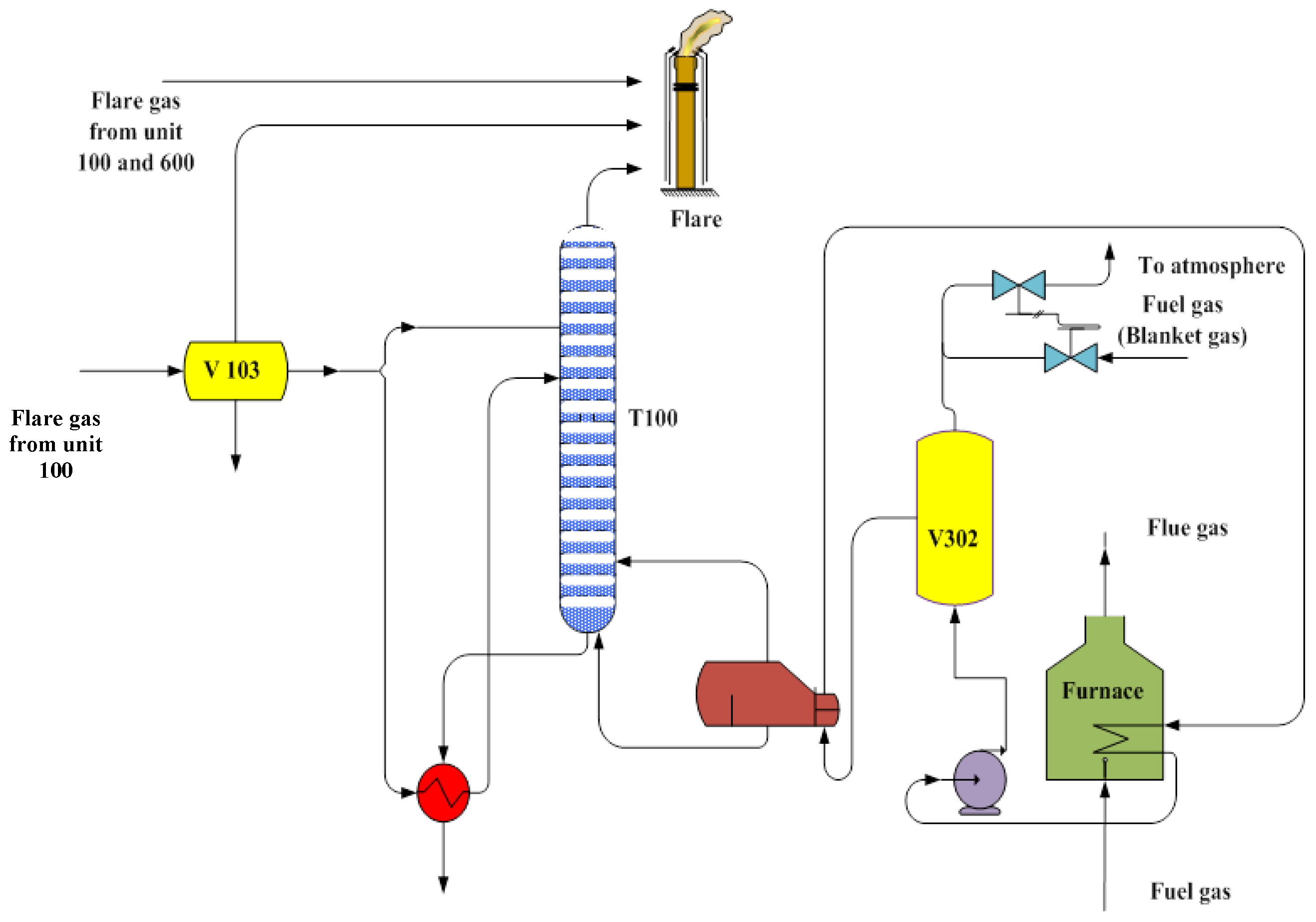
Figure 1 shows the process flow diagram of “Unit 300” of the aforementioned domestic gas refinery.
Supplementary Figure S1 shows the 3D scheme of the “Unit 300” furnace and its surroundings.
In this refinery, 20% excess air is used for the furnace. Therefore, a small amount of CO and oxygen is present in the flue gas.
The composition and conditions of fuel gas and flue gas are shown in
Table 3 and
Table 4. Fuel gas is supplied from a pipeline in “Unit 100”, which comes from a sweet gas reservoir. This made fuel gas and flue gas free of hydrogen sulfide.
2.2. Process Design for Hydrogen Generation
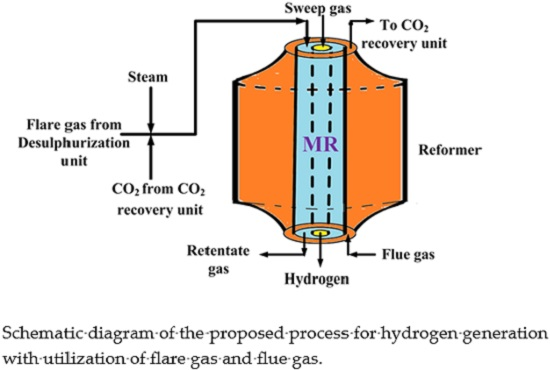
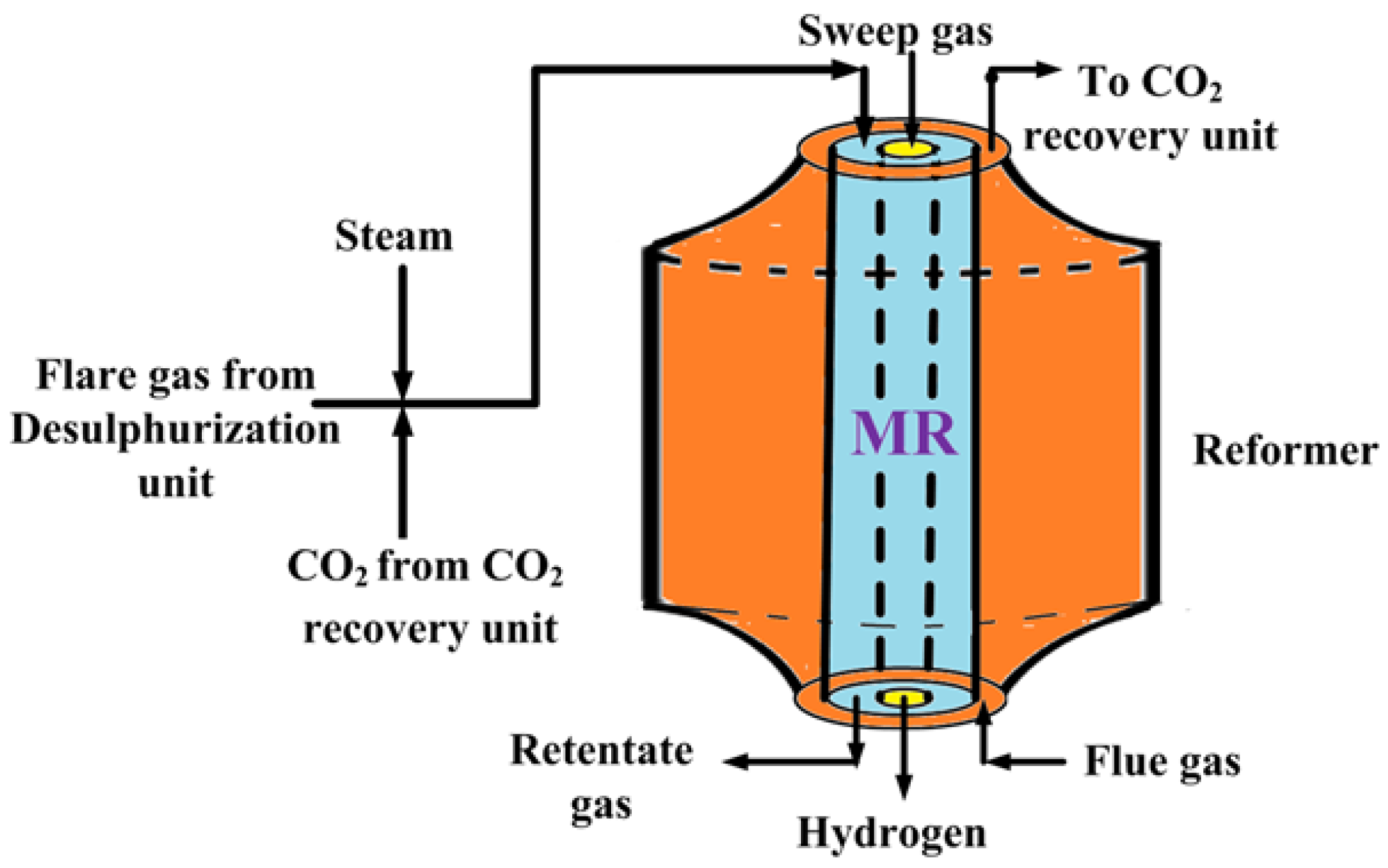
Figure 2 shows a schematic diagram of the proposed process for pure hydrogen generation. The mixture of sweet flare gas (mostly containing methane), steam (from steam generation unit) and CO
2 (from CO
2 recovery unit) is preheated by heat exchanging and, then, fed to the MR, heated by flue gas (mostly containing CO
2), for carrying out the mixed reforming reaction at the set operating temperature.
Supplementary Figure S2 shows a schematic diagram of the CO
2 recovery unit, in which the mixture of flue gas and the retentate stream (after a polymeric membrane separation useful for separating CH
4 and H
2) pass to the absorber after cooling by a flue gas cooler.
The flare gas stream contains a small amount of hydrogen sulfide that was previously removed by a desulphurization unit to avoid the Pd-Ag membrane poisoning and of the catalyst, as well. The hydrogen produced during the reaction and permeated through the dense Pd-Ag as a pure stream constitutes the outgoing permeate stream for PEMFC supplying. The other outgoing stream (retentate) is directed to the CO2 recovery unit because it is rich in CO2 after a polymeric membrane separation step to separate CH4 and H2 from this stream, indirectly contributing to mitigating the GHGs in the atmosphere.
In this work, a novel process is proposed to produce pure hydrogen from waste gases (flare gas and flue gas) of a domestic gas refinery through the utilization of a Pd-Ag MR. The used data related to the characteristics of the feed stream to be flowed into the MR were obtained by a simulation of the aforementioned refinery (the same software as reported in [
6] was used). Then, the composition and conditions of feed the stream before entering in the MR are shown in
Table 5 and
Table 6. The MR was operated at 450 °C (as the maximum temperature limit of the used Pd-Ag membrane) and between 150 and 350 kPa (the latter representing the maximum pressure limit of the used Pd-Ag membrane).
3. Experimental Procedure
3.1. Experimental Setup
An experimental setup was built to investigate the production of PEMFC-grade hydrogen from mixed reforming of a model feed gas mixture (flue gas + flare gas + steam) by means of a dense Pd
77-Ag
23 MR packed with a non-commercial Ni(7.5 wt%)/CeO
2 catalyst provided by CNR-ITAE (Messina, Italy), chosen for its low cost and high coke resistance [
77,
78].
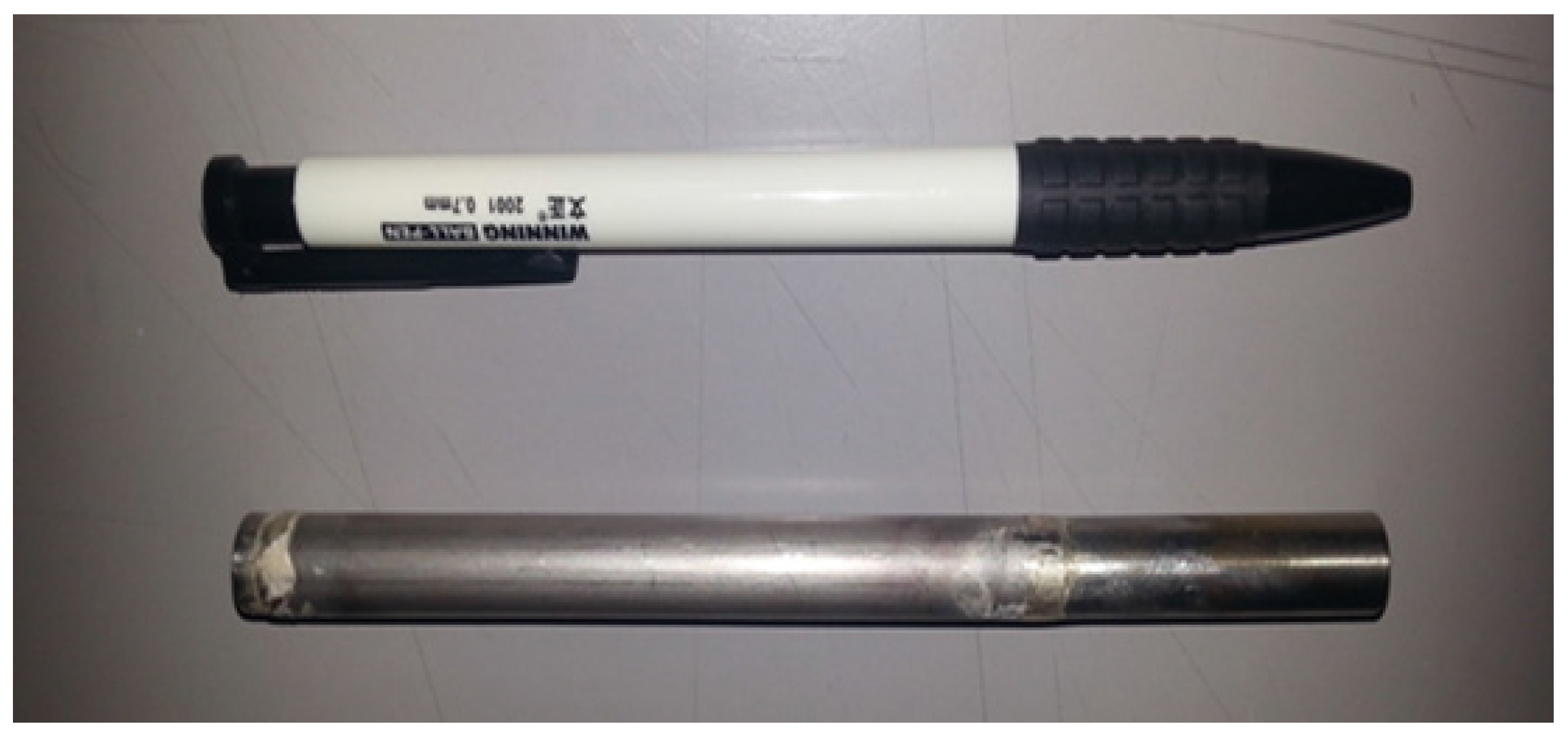
The MR consists of a tubular stainless steel module (length 280 mm, i.d. 20 mm) containing a tubular commercial dense self-supported Pd-Ag membrane provided by Johnson & Matthey Co. (Royston, UK), with a wall thickness of 150 mμm, o.d. 10 mm and 10 cm as the length (
Figure 3).
The MR is heated by means of a heating tape connected to a temperature controller. The operating temperature is measured by a thermocouple inserted into the MR lumen. The reaction pressure is regulated by means of a back-pressure controller placed at the outlet side of the retentate stream. The permeate pressure is kept constant during the whole experimental campaign at 100 kPa. CH4, CO2, N2 and pure H2 (N2 also used as the standard gas and H2 used for the catalyst reduction) are supplied by means of Brooks Instruments 5850S mass-flow controllers, driven by a Lira (Turin, Italy) software. H2O is supplied by means of a volumetric pump (type FMQG6) provided by General Control (Milan, Italy).
CH
4, CO
2, N
2 and steam feed molar flow rates are 1.03 × 10
−3, 5.27 × 10
−4, 7.43 × 10
−4 and 4.11 × 10
−3 mol/min, respectively, while the CH
4/CO
2/H
2O reactant feed ratio is 1/0.5/4 with a GHSV of 1020 h
−1. This feed ratio is chosen taking into account the simulation results summarized in
Table 5 and kept constant during all of the experimental tests. N
2 was also used as a sweep-gas (counter-current configuration with respect to the feed) and flowed into the MR permeate side with a volume flow rate of 1.27 × 10
−3 mol/min.
The water was vaporized in a pre-heater prior to entering the MR reaction side.
The outlet stream from the retentate zone is passed through a cold trap in order to remove the unreacted H2O, and then, the retentate and the permeate streams are analyzed simultaneously by means of a temperature-programmed HP 6890 gas chromatograph (GC) provided by Hewlett-Packard (Palo Alto, CA, USA). To ensure the reproducibility of the results, each experimental point of this work represents an average value of, at least, 10 experimental results, taken in around 140 min per reaction test at steady state conditions.
3.2. Permeation Tests and Catalyst Activation
Prior to the reaction tests, the Pd-Ag membrane was characterized under pure gas permeation in the absence of an active sweep. Then, pure N2 and H2 were flowed in the MR at 350, 400 and 450 °C. The volume flow rate of permeating hydrogen through the membrane is measured by means of a bubble flow meter (the volume of the bubble flow meter used to measure the H2 permeating flow was 10 mL). N2 was used only to check whether the membrane is permeable to another gas besides H2 and to ensure its full hydrogen perm-selectivity (the volume of the bubble flow meter used to check the presence of N2 permeating flow was 100 mL).
Then, the reactor was cooled down at room temperature and packed with 2.8 g of Ni/CeO2 catalyst. Successively, the MR was heated up again to 450 °C for realizing the reaction tests in the reaction pressure range between 100 and 350 kPa. Before the reaction, the catalyst was preheated using N2 at 450 °C under atmospheric pressure for 3 h and, afterwards, reduced by using H2 (1.5 × 10⁻³ mol/min) at the same temperature for 2 h.
It should be considered that, in order to ensure the accuracy of the experimental results, after each reaction test, the hydrogen permeating flux through the dense commercial Pd-Ag membrane was measured and compared to the values obtained during the permeation tests.
3.3. Equations
The following equations are used for calculating the methane conversion and hydrogen recovery:
In Equations (4)–(6), the subscript “OUT” means the total outlet molar flow rate of CH4, while "IN" refers to its inlet molar flow rate (mol/min), while “perm” and “ret” mean the hydrogen molar flow rate (mol/min) in the permeate and retentate side, respectively.
Equation (7) represents the Sieverts–Fick law useful for describing the hydrogen permeating flux
through the dense Pd-Ag membrane. As reported below, the exponent of the hydrogen partial pressures in the retentate and permeate sides is equal to 0.5, a typical value for full hydrogen perm-selective membranes when the bulk diffusion of H
2 through the palladium layers is the rate-limiting step at low pressure.
Equation (8) describes the relationship between the hydrogen permeability (
with the temperature as an Arrhenius-like law.
In the equations reported above: , Ea, R, T and δ represent the pre-exponential factor, apparent activation energy, universal gas constant, absolute temperature and the Pd-Ag membrane thickness, respectively. Furthermore, and indicate the hydrogen partial pressure in the retentate and permeate zones.
4. Results and Discussion
4.1. Hydrogen Permeation Tests
During the permeation tests, the H2 volume flow rate permeating through the membrane was evaluated in the pressure and temperature ranges between 100 and 300 kPa and 350 and 450 °C, respectively. At the same conditions, N2 permeation was also checked, observing the absence of its permeation in the whole experimental campaign. The calculated Ea and for the dense Pd-Ag membrane are 13,412 J/mol and 2.16 × 10⁻⁷ mol/m·s·Pa0.5, respectively.
4.2. Reaction Tests
According to the simulation results reported in
Table 6, the operating temperature for the MR was kept constant at 450 °C in the whole experimental campaign of the reaction tests, and the effect of pressure on the reaction conversion, hydrogen recovery and hydrogen yield was investigated.
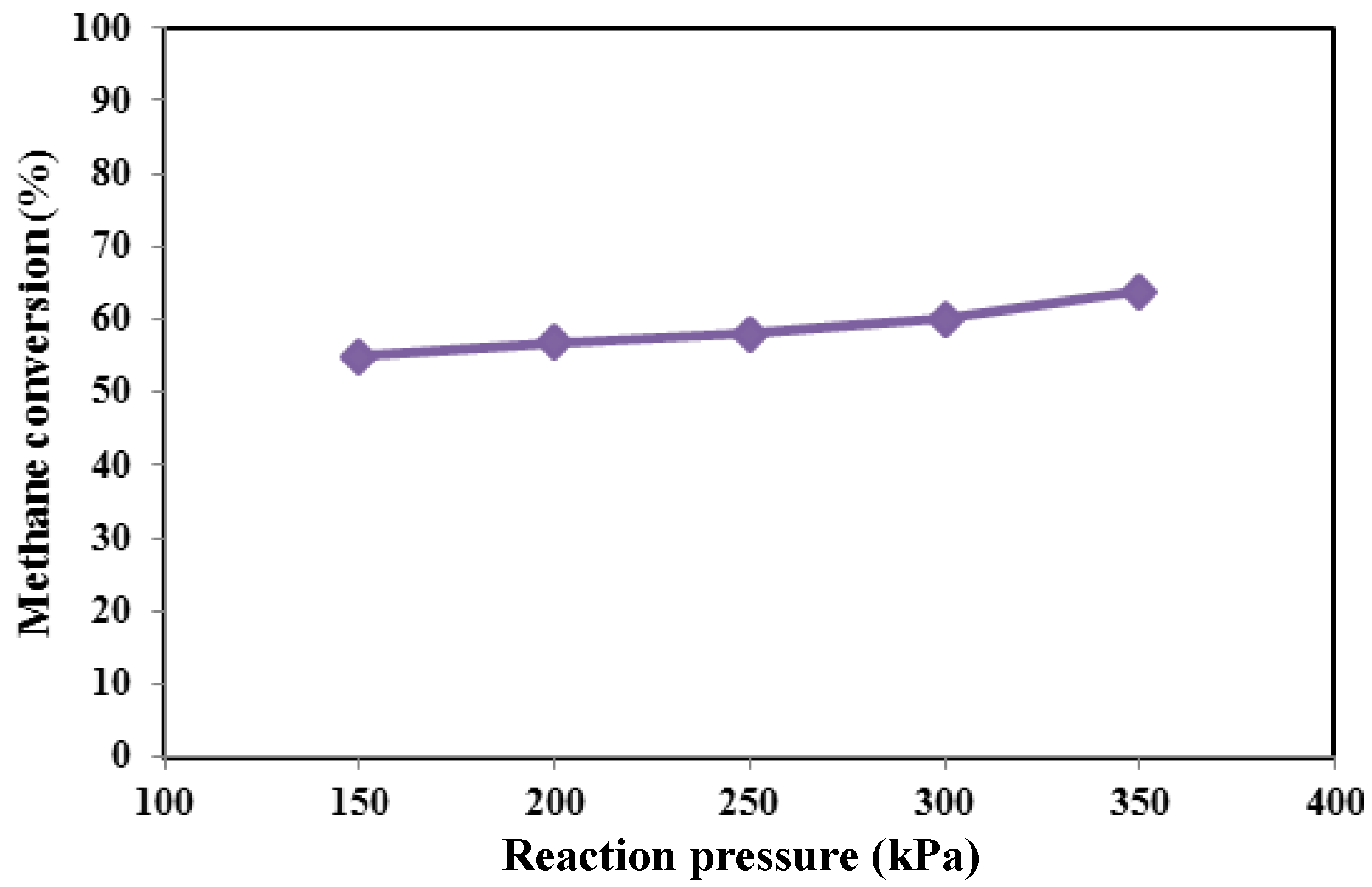
However, due to the low composition of propane and ethane, they were neglected in the real feeding mixture. In
Figure 4,
Figure 5 and
Figure 6, methane conversion, hydrogen yield and hydrogen recovery are sketched at different pressures and 450 °C.
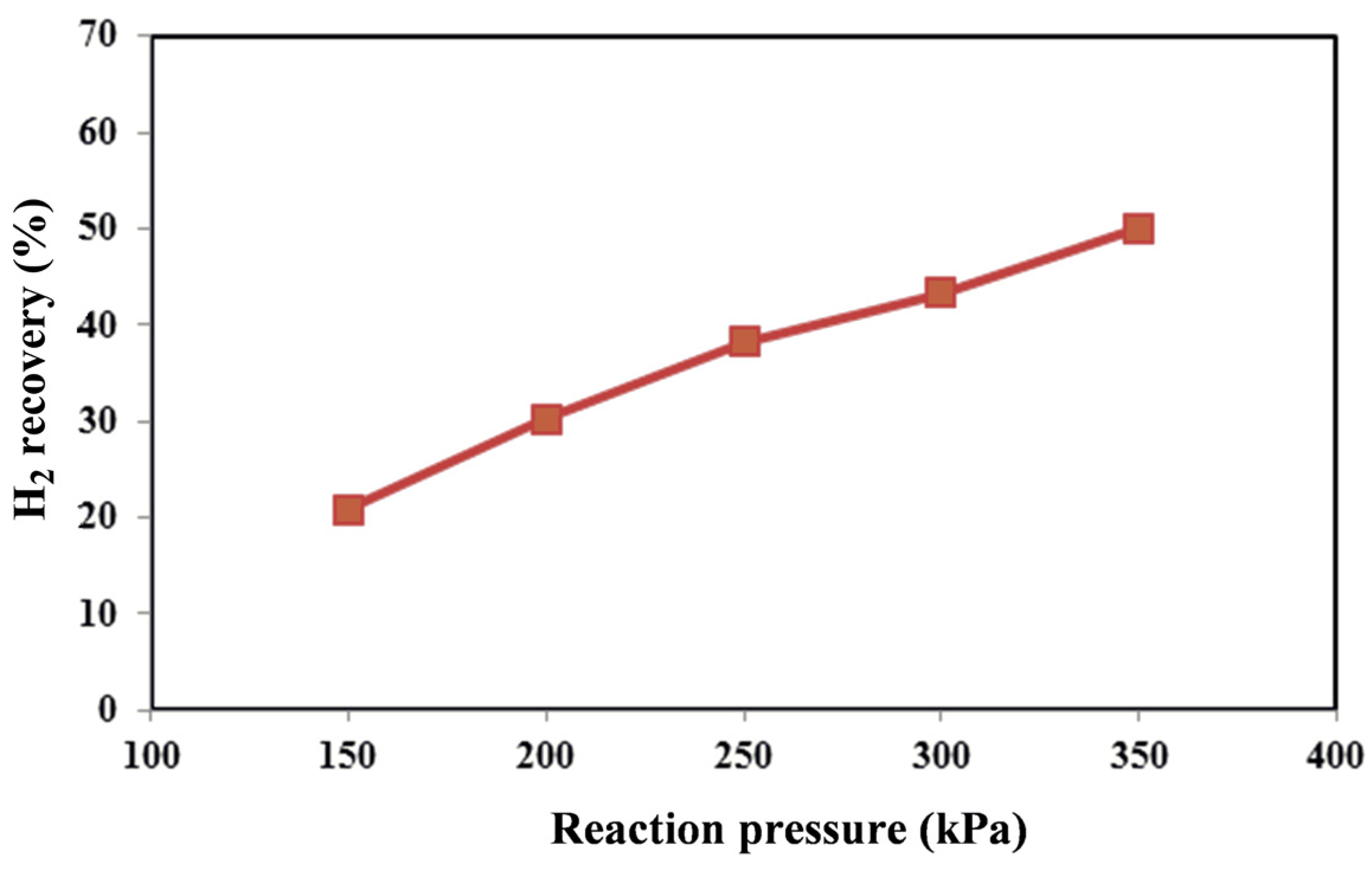
Since the considered reforming reactions proceed with the increase of the moles’ number, in a TR, it would be expected that, from a thermodynamic point of view, higher methane conversions could be obtained at lower pressures. On the contrary, in the Pd-Ag MR by increasing the reaction pressure, an increase of the hydrogen permeation driving force is induced, favoring a higher hydrogen removal from the reaction side towards the permeate side with a consequent higher hydrogen recovery (
Figure 6). Due to Le Chatelier’s principle, this makes possible a shift of the reforming reactions from the reactants to the products with a consequent enhancement of the conversion (shift effect) (
Figure 4).
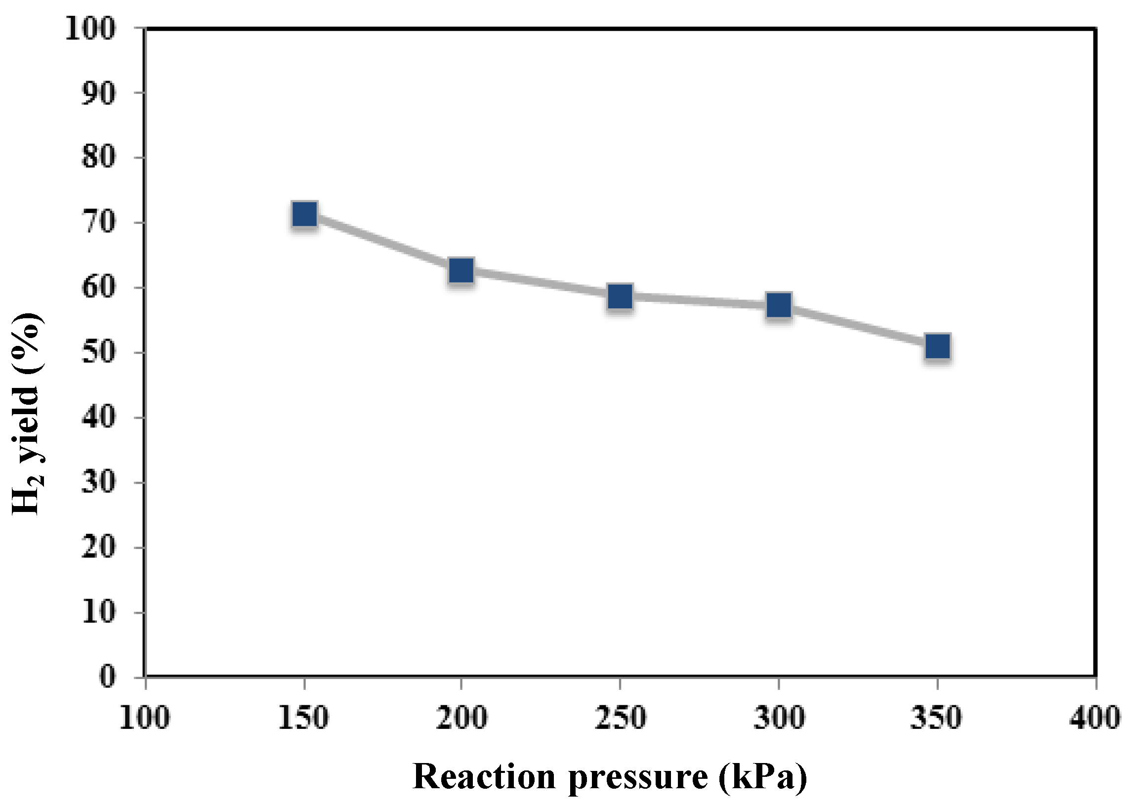
Furthermore, by using the non-commercial Ni-based catalyst in the MR, no coke formation was noticed at the operating conditions investigated in this work. As the best result, at 450 °C, the maximum methane conversion and hydrogen recovery were achieved at 350 kPa of about 64% and 50%, respectively. On the contrary, the hydrogen yield showed a decrease from 350 down to 150 kPa (
Figure 5).
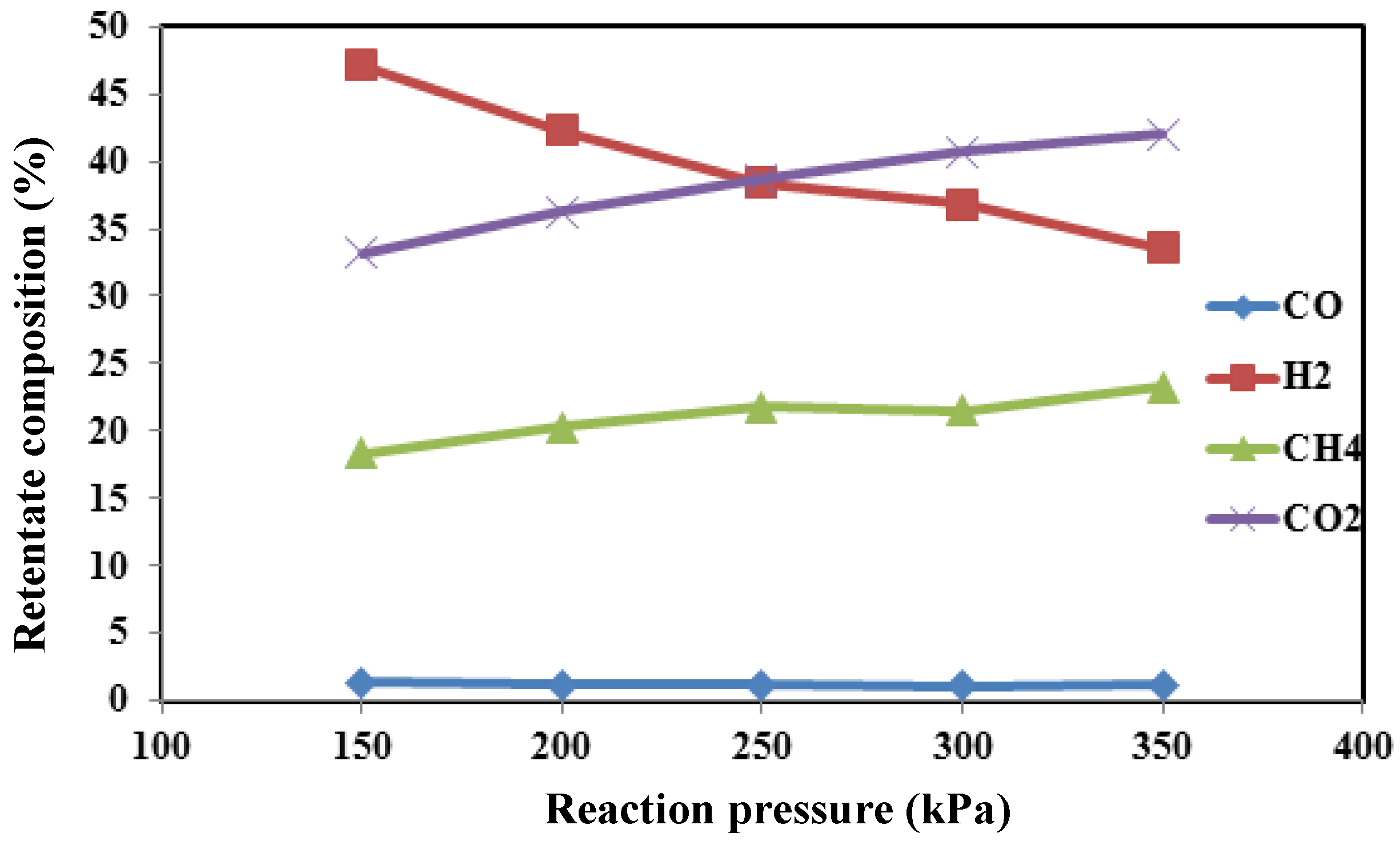
Figure 7 shows the composition of the gaseous products in the retentate zone versus pressure. It confirms that, at a higher pressure, although the CO
2 is consumed in the dry reforming reaction (Equation (2)), CO
2 content increases due to the higher conversion in the steam reforming reaction (Equation (1)). Furthermore, at higher pressure, the retentate stream is more concentrated in CO
2, useful for further treatment of CO
2, via polymeric membrane separation from CH
4 and H
2 and its storage through the CO
2 recovery unit.
In the meantime, the hydrogen composition decreases because of the higher hydrogen recovery at higher pressures.
5. MR for the Domestic Gas Refinery
This section attempts the calculation of the surface area and hydrogen production of the MR for the proposed process in the domestic gas refinery.
In practice, the scale-up of the membrane system should be useful to calculate the membrane area for the aforementioned process, with separation data coming from the previous experimental results.
In this regard, according to what was proposed by Gooding [
79] for steady state plug flow membrane systems, the following equation is applicable:
In this equation, W and Q0 are the membrane area per unit length in the z-direction and the initial volumetric flow rate of the feed in the retentate zone, respectively. It is obvious that the product Wz gives the total membrane area requirement.
By using the scale-up method [
79], the calculations showed that, if we consider a uniform hydrogen distribution in retentate zone, the membrane area should be 930 m
2, and 150 kg/h (3.6 t/d) hydrogen could be produced from the proposed process at 350 kPa and 450 °C.
It should be mentioned that, although the surface area of the simulated MR for the domestic gas refinery is relatively high because of using flare gas as an inlet feed, the costs regarding natural gas feed are eliminated. Furthermore, the economic advantages are gained from low-temperature operation and using the heat of flue gas as a source of energy for the mixed reforming reaction. These advantages besides the benefits of the mixed reforming reaction make the proposed process attractive compared to the conventional processes for hydrogen production in large-scale plants.
Nevertheless, unsupported Pd-based membranes offer full H2 perm-selectivity with respect to all of the other gases, but owing to the low availability of Pd in nature, they result in being very expensive. An alternative option could be the supported thin Pd-membranes, stable at high temperatures and exhibiting relatively high hydrogen permeability, resulting in being available at moderate cost due to the lower content of palladium.
6. Conclusions
In this research, a novel process was designed to produce hydrogen from waste gas (flare gas + flue gas) of a domestic gas refinery. The proposed process was simulated to find the condition of the feed stream for producing pure hydrogen in a MR. Then, an experimental setup at bench scale was built up for evaluating the hydrogen production via the mixed reforming reaction through an MR housing a commercial dense Pd-Ag membrane, packed with a Ni/CeO2 catalyst at 450 °C, pressure range of 100–350 kPa and GHSV ~1000 h−1. In this regard, a simulated feed mixture with a CH4/CO2/H2O reactant feed molar ratio of 1/0.5/4 was used to carry out the mixed reforming reaction tests for producing pure hydrogen.
The results showed that the higher the reaction pressure, the higher the conversion and hydrogen recovery due to the shift effect realized in the MR. As a result, at 350 kPa, the MR was able to achieve more than 60% methane conversion and around 50% hydrogen recovery. Consequently, the results of the experimental tests were used to estimate the surface area and hydrogen production at a larger scale for the domestic gas refinery.
All in all, the following advantages could be gained with the proposed process for the domestic gas refinery:
(1) Prevent CO2 and hazardous materials emissions to the atmosphere by utilization of flare gas and flue gas as a waste product of the refinery to produce pure hydrogen in an MR.
(2) Using the benefits of the mixed reforming reaction for producing hydrogen.
(3) Low-temperature operation.
(4) The cost of natural gas used as an inlet feed of the hydrogen generation plants leads to an increase in costs; however, the flare gas is used as an inlet feed, and consequently, costs regarding natural gas feed are eliminated.
(5) By using flue gas as a source of energy, the cost of providing energy (which is the most expensive part of the hydrogen generation plants) is omitted.
(6) The exhaust flue gas is used as a feed stream to produce CO2 for the mixed reforming reaction in the CO2 recovery unit.
Supplementary Materials
The following are available online at
www.mdpi.com/2227-9717/4/3/33/s1, Figure S1: The industrial furnace of the domestic gas refinery; Figure S2: Process flow diagram of the CO
2 recovery unit.
Acknowledgments
The Authors would like to thank the Italian Ministry of Economic Development (MISE) for the funds received by Microgen30 project, contract number EE01_00013, to develop part of the research of this work.
Author Contributions
S.M.J., A.I. and A.B. conceived and designed the experiments; S.M.J. and G.B. performed the experiments; A.I., F.D. and S.M.J. analyzed the data; A.V., A.S. and M.R.R. contributed reagents/materials/analysis tools; S.M.J. and A.I. wrote the paper.
Conflicts of Interest
The authors declare no conflict of interest.
List of Symbols and Acronyms
| GHG | green-house gases |
| GTL | gas to liquid |
| MR | membrane reactor |
| TR | traditional reactor |
| PEMFC | proton exchange membrane fuel cell |
| W | membrane area per unit length in the z-direction |
| Q0 | initial volumetric flow rate of the feed in the retentate zone |
| Ea | apparent activation energy |
| hydrogen flux permeating through the membrane |
| Pe0 | pre-exponential factor |
| hydrogen permeability |
| hydrogen partial pressure in the permeate side |
| hydrogen partial pressure in the retentate side |
| R | universal gas constant |
| T | absolute temperature |
| δ | membrane thickness |
References
- Fan, M.S.; Abdullah, A.Z.; Bhatia, S. Catalytic technology for carbon dioxide reforming of methane to synthesis gas. Chem. Cat. Chem. 2009, 1, 192–208. [Google Scholar] [CrossRef]
- DoE, U.S. Waste Heat Reduction and Recovery for Improving Furnace Efficiency Productivity and Emissions Performance; U.S. Department of Energy: Washington, DC, USA, 2004.
- Schurz, A.; Andersson, L.; Storm, H. A 12-MW gas turbine cogeneration plant fired with refinery gases. Chart. Mech. Eng. 1982, 29, 63–66. [Google Scholar]
- Broeker, R.J. Combined-cycle cogeneration to power oil refinery. Mech. Eng. 1986, 108, 42–45. [Google Scholar]
- Najar, S.H.; Habeebullah, M.B. Energy conservation in the refinery by utilizing reformed fuel gas and furnace flue gases. Heat Recovery Syst. CHP 1991, 11, 517–521. [Google Scholar] [CrossRef]
- Rahimpour, M.R.; Jokar, S.M. Feasibility of flare gas reformation to practical energy in Farashband gas refinery: No gas flaring. J. Hazard. Mater. 2012, 209–210, 204–217. [Google Scholar] [CrossRef] [PubMed]
- Rahimpour, M.R.; Jamshidnejad, Z.; Jokar, S.M.; Karimi, G.; Ghorbani, A.; Mohammadi, A.H. A comparative study of three different methods for flare gas recovery of Asalouye Gas Refinery. J. Nat. Gas Sci. Eng. 2012, 4, 17–28. [Google Scholar] [CrossRef]
- Saidi, M.; Siavashi, F.; Rahimpour, M.R. Application of solid oxide fuel cell for flare gas recovery as a new approach; a case study for Asalouyeh gas processing plant, Iran. J. Nat. Gas Sci. Eng. 2014, 17, 13–25. [Google Scholar] [CrossRef]
- Abdulrahman, A.O.; Huisingh, D.; Hafkamp, W. Sustainability improvements in Egypt's oil & gas industry by implementation of flare gas recovery. J. Clean. Prod. 2015, 98, 116–122. [Google Scholar]
- Reijerkerk, S.R.; Jordana, R.; Nijmeijer, K.; Wessling, M. Highly hydrophilic, rubbery membranes for CO2 capture and dehydration of flue gas. Int. J. Greenhouse Gas Control 2011, 5, 26–36. [Google Scholar] [CrossRef]
- Khalilpour, R.; Mumford, K.; Zhai, H.; Abbas, A.; Stevens, G.; Rubin, E.S. Membrane-based carbon capture from flue gas: A review. J Clean. Prod. 2015, 103, 286–300. [Google Scholar] [CrossRef]
- He, X.; Fu, C.; Hägg, M.B. Membrane system design and process feasibility analysis for CO2 capture from flue gas with a fixed-site-carrier membrane. Chem. Eng. J. 2015, 268, 1–9. [Google Scholar] [CrossRef]
- Hassanlouei, R.N.; Pelalak, R.; Daraei, A. Wettability study in CO2 capture from flue gas using nano porous membrane contactors. Int. J. Greenhouse Gas Control 2013, 16, 233–240. [Google Scholar] [CrossRef]
- Halmann, M.; Steinfeld, A. Hydrogen production and CO2 fixation by flue-gas treatment using methane tri-reforming or coke/coal gasification combined with lime carbonation. Int. J. Hydrogen Energy 2009, 34, 8061–8066. [Google Scholar] [CrossRef]
- Chen, W.H.; Lin, M.R.; Leu, T.S.; Du, S.W. An evaluation of hydrogen production from the perspective of using blast furnace gas and coke oven gas as feedstocks. Int. J. Hydrogen Energy 2011, 36, 11727–11737. [Google Scholar] [CrossRef]
- Liberatore, R.; Lanchi, M.; Caputo, G.; Felici, C.; Giaconia, A.; Sau, S.; Tarquini, P. Hydrogen production by flue gas through sulfur-iodine thermochemical process: Economic and energy evaluation. Int. J. Hydrogen Energy 2012, 37, 8939–8953. [Google Scholar] [CrossRef]
- Rostrup-Nielsen, J.R.; Rostrup-Nielsen, T. Large-Scale Hydrogen Production. Cattech 2002, 6, 150–159. [Google Scholar] [CrossRef]
- Wee, J.H. Applications of proton exchange membrane fuel cell systems. Renew. Sustain. Energy Rev. 2007, 11, 1720–1738. [Google Scholar] [CrossRef]
- Ahmed, S.; Krumpelt, M. Hydrogen from hydrocarbon fuels for fuel cells. Int. J. Hydrogen Energy 2001, 26, 291–301. [Google Scholar]
- Rabenstein, G.; Hacker, V. Hydrogen for fuel cells from ethanol by steam-reforming, partial-oxidation and combined autothermal reforming: A thermodynamic analysis. J. Power Sour. 2008, 185, 1293–1304. [Google Scholar] [CrossRef]
- Seo, Y.S.; Shirley, A.; Kolaczkowski, S.T. Evaluation of thermodynamically favourable operating conditions for production of hydrogen in three different reforming technologies. J Power Sour. 2002, 108, 213–225. [Google Scholar] [CrossRef]
- Rostrupnielsen, J.R.; Hansen, J.B. CO2-reforming of methane over transition metals. J. Catal. 1993, 144, 38–43. [Google Scholar] [CrossRef]
- Ruckenstein, E.; Hu, Y.H. The effect of precursor and preparation conditions of MgO on the CO2 reforming of CH4 over NiO/MgO catalysts. Appl. Catal. A: Gen. 1997, 154, 185–205. [Google Scholar] [CrossRef]
- Zhang, Z.; Verykios, X.E. A stable and active nickel-based catalyst for carbon dioxide reforming of methane to synthesis gas. J. Chem. Soc. Chem. Commun. 1995, 71–72. [Google Scholar] [CrossRef]
- Zhang, Z.; Verykios, X.E. Carbon dioxide reforming of methane to synthesis gas over Ni/La2O3 catalysts. Appl. Catal. A: Gen. 1996, 138, 109–133. [Google Scholar]
- Cui, Y.; Zhang, H.; Xu, H.; Li, W. The CO2 reforming of CH4 over Ni/La2O3/α-Al2O3 catalysts: The effect of La2O3 contents on the kinetic performance. Appl. Catal. A: Gen. 2007, 331, 60–69. [Google Scholar] [CrossRef]
- Kathiraser, Y.; Oemar, U.; Saw, E.T.; Li, Z.; Kawi, S. Kinetic and mechanistic aspects for CO2 reforming of methane over Ni based catalysts (review). Chem. Eng. J. 2015, 278, 62–78. [Google Scholar] [CrossRef]
- Li, C.; Fu, Y.; Bian, G.; Xie, Y.; Hu, T.; Zhang, J. Effect of steam in CO2 reforming of CH4 over a Ni/CeO2-ZrO2-Al2O3 catalyst. Kinet. Cat. 2004, 45, 679–683. [Google Scholar] [CrossRef]
- Snoeck, J.W.; Froment, G.; Fowles, M. Kinetic evaluation of carbon formation in steam/CO2-natural gas reformers. Influence of the catalyst activity and alkalinity. Int. J. Chem. Reac. Eng. 2003, 1, 1–16. [Google Scholar] [CrossRef]
- Abashar, M.E.E. Coupling of steam and dry reforming of methane in catalytic & fluidized bed membrane reactors. Int. J. Hydrogen Energy 2004, 29, 799–808. [Google Scholar]
- Froment, G.F. Production of synthesis gas by steam- and CO2-reforming of natural gas. J. Mol. Catal. A: Chem. 2000, 163, 147–156. [Google Scholar]
- Iulianelli, A.; Liguori, S.; Huang, Y.; Basile, A. Model biogas steam reforming in a thin Pd-supported membrane reactor to generate clean hydrogen for fuel cells. J. Power Sour. 2015, 273, 25–32. [Google Scholar] [CrossRef]
- Koo, K.Y.; Lee, S.; Jung, U.H.; Roh, H.; Yoon, W.L. Syngas production via combined steam and carbon dioxide reforming of methane over Ni–Ce/MgAl2O4 catalysts with enhanced coke resistance. Fuel Process Technol. 2014, 119, 151–157. [Google Scholar] [CrossRef]
- Lemonidou, A.A.; Vasalos, I.A. Carbon dioxide reforming of methane over 5 wt.% Ni/CaO-Al2O3 catalyst. Appl. Catal. A: Gen. 2002, 228, 227–235. [Google Scholar] [CrossRef]
- Özkara-Aydınoğlu, Ş. Thermodynamic equilibrium analysis of combined carbon dioxide reforming with steam reforming of methane to synthesis gas. Int. J. Hydrogen Energy 2010, 35, 2821–2828. [Google Scholar] [CrossRef]
- Choudhary, V.R.; Rajput, A.M. Simultaneous carbon dioxide and steam reforming of methane to syngas over NiO–CaO catalyst. Ind. Eng. Chem. Res. 1996, 35, 3934–3939. [Google Scholar] [CrossRef]
- Hegarty, M.E.S.; O’Connor, A.M.; Ross, J.R.H. Syngas production from natural gas using ZrO2-supported metals. Catal. Today 1998, 42, 225–232. [Google Scholar] [CrossRef]
- Choudhary, V.R.; Mondal, K.C. CO2 reforming of methane combined with steam reforming or partial oxidation of methane to syngas over NdCoO3 perovskite-type mixed metal-oxide catalyst. Appl. Energy 2006, 83, 1024–1032. [Google Scholar] [CrossRef]
- Noronha, F.B.; Shamsi, A.; Taylor, C.; Fendley, E.C.; Stagg-William, S.; Resasco, D.E. Catalytic performance of Pt/ZrO2 And Pt/Ce-ZrO2 catalysts on CO2 reforming of CH4 coupled with steam reforming or under high pressure. Catal. Lett. 2003, 90, 13–21. [Google Scholar] [CrossRef]
- Sheng, M.; Yang, H.; Cahela, D.; Tatarchuk, B.J. Novel catalyst structures with enhanced heat transfer characteristics. J. Catal. 2011, 281, 254–262. [Google Scholar] [CrossRef]
- Boger, T.; Herbel, A.K. Heat transfer in conductive monolith structures. Chem. Eng. Sci. 2005, 60, 1823–1835. [Google Scholar] [CrossRef]
- Slagtern, A.; Oblbye, U.; Blom, R.; Dahl, I.M.; Fjellvag, H. In situ XRD characterization of La-Ni-Al-O model catalysts for CO2 reforming of methane. Appl. Catal. A: Gen. 1996, 145, 375–388. [Google Scholar] [CrossRef]
- Valderrama, G.; Goldwasser, M.R.; Navarro, C.U.; Tatibouet, J.M.; Barrault, J.; Batiot-Dupeyrat, C.; Martinez, F. Dry reforming of methane over Ni perovskite type oxides. Catal. Today 2005, 108, 785–791. [Google Scholar] [CrossRef]
- Hu, Y.H.; Ruckenstein, E. An optimum NiO content in the CO2 reforming of CH4 with NiO/MgO solid solution catalysts. Catal. Lett. 1996, 36, 145–149. [Google Scholar] [CrossRef]
- Ruckenstein, E.; Wang, H.Y. Carbon deposition and catalytic deactivation during CO2 reforming of CH4 over Co/Al2O3. J. Catal. 2002, 205, 289–293. [Google Scholar] [CrossRef]
- Iulianelli, A.; Liguori, S.; Wilcox, J.; Basile, A. Advances on methane steam reforming to produce hydrogen through membrane reactors technology: A review. Catal. Rev. Sci. Eng. 2016, 58, 1–35. [Google Scholar] [CrossRef]
- Pompeo, F.; Nichio, N.N.; Souza, M.M.V.M.; Cesar, D.V.; Ferretti, O.A.; Schmal, M. Study of Ni and Pt catalysts supported on α-Al2O3 and ZrO2 applied in methane reforming with CO2. Appl. Catal. A: Gen. 2007, 316, 175–183. [Google Scholar] [CrossRef]
- Gigola, C.E.; Moreno, M.S.; Costilla, I.; Sánchez, M.D. Characterization of Pd-CeOx interaction on α-Al2O3 support. Appl. Surf. Sci. 2007, 254, 325–329. [Google Scholar] [CrossRef]
- Múnera, J.F.; Irusta, S.; Cornaglia, L.M.; Lombardo, E.A.; Cesar, D.V.; Schmal, M. Kinetics and reaction pathway of the CO2 reforming of methane on Rh supported on lanthanum based solid. J. Catal. 2006, 245, 25–34. [Google Scholar] [CrossRef]
- Hashimoto, K.; Watase, S.; Toukai, N. Reforming of methane with carbon dioxide over a catalyst consisting of ruthenium metal and cerium oxide supported on mordenite. Catal. Lett. 2002, 80, 147–152. [Google Scholar] [CrossRef]
- Nagaoka, K.; Seshan, K.; Aika, K.; Lercher, J.A. Carbon deposition during carbon dioxide reforming of methane-comparison between Pt/Al2O3 and Pt/ZrO2. J. Catal. 2001, 197, 34–42. [Google Scholar] [CrossRef]
- Bradford, M.C.J.; Vannice, M.A. CO2 reforming of CH4. Catal. Rev. 1999, 41, 1–42. [Google Scholar] [CrossRef]
- Barroso-Quiroga, M.M.; Castro-Luna, A.E. Catalytic activity and effect of modifiers on Ni-based catalysts for the dry reforming of methane. Int. J. Hydrogen Energy 2010, 35, 6052–6056. [Google Scholar] [CrossRef]
- Subramani, V.; Sharma, P.; Zhang, L.; Liu, K.; Song, C. Hydrogen and Syngas Production and Purification Technologies: Hydrocarbon Processing for H2 Production; Wiley: New York, NY, USA, 2010; pp. 14–126. [Google Scholar]
- Danilova, M.M.; Fedorova, Z.A.; Zaikovskii, V.I.; Porsin, A.V.; Kirillov, V.A.; Krieger, T.A. Porous nickel-based catalysts for combined steam and carbon dioxide reforming of methane. Appl. Catal. B: Environ. 2014, 147, 858–863. [Google Scholar]
- Li, L.; Borry, R.W.; Iglesia, E. Design andoptimization of catalysts and membrane reactors for the non-oxidative conversion of methane. Chem. Eng. Sci. 2002, 57, 4595–4604. [Google Scholar] [CrossRef]
- Rostrup-Nielsen, J.R.; Christiansen, L.J.; Bak Hansen, J.H. Activity of steam reforming catalysts: Role and assessment. Appl. Catal. 1988, 43, 287–303. [Google Scholar] [CrossRef]
- Rostrup-Nielsen, J.R.; Sehested, J.; Nørskov, J.K. Hydrogen and synthesis gas by steam- and CO2 reforming. Adv. Catal. 2002, 47, 65–139. [Google Scholar] [CrossRef]
- Chen, Y.; Wang, Y.; Xu, H.; Xiong, G. Efficient production of hydrogen from natural gas steam reforming in palladium membrane reactor. Appl. Catal. B Environ. 2008, 80, 283–294. [Google Scholar] [CrossRef]
- Liu, Z.W.; Roh, H.S.; Jun, K.W. Important factors on carbon dioxide reforming of methane over nickel-based catalysts. J. Ind. Eng. Chem. 2003, 9, 753–761. [Google Scholar]
- Bae, J.W.; Kim, A.R.; Baek, S.C.; Jun, K.W. The role of CeO2-ZrO2 distribution on the Ni/MgAl2O4 catalyst during the combined steam and CO2 reforming of methane. React. Kinet. Mech. Catal. 2011, 104, 377–388. [Google Scholar] [CrossRef]
- Jun, K.W.; Baek, S.C.; Bae, J.W.; Min, K.S.; Song, S.L.; Oh, T.Y. Hyundai Heavy Industries Corporation and Korea Research Institute of Chemical Technology. Patent EP 2308594 A2, 2009. [Google Scholar]
- Wei, J.M.; Iglesia, E. Isotopic and kinetic assessment of the mechanism of reactions of CH4 with CO2 or H2O to form synthesis gas and carbon on nickel catalysts. J. Catal. 2004, 224, 370–383. [Google Scholar] [CrossRef]
- Choudhary, V.R.; Uphade, B.S.; Mamman, A.S. Simultaneous steam and CO2 reforming of methane to syngas over NiO/MgO/SA-5205 in presence and absence of oxygen. Appl. Catal. A: Gen. 1998, 168, 33–46. [Google Scholar] [CrossRef]
- Sona, I.H.; Lee, S.J.; Soon, A.; Roh, H.; Leed, H. Steam treatment on Ni/Υ-Al2O3 for enhanced carbon resistance in combined steam and carbon dioxide reforming of methane. Appl. Catal. B: Environ. 2013, 134–135, 103–109. [Google Scholar] [CrossRef]
- Koo, K.Y.; Lee, S.; Jung, U.H.; Roh, H.; Yoon, W.L. Syngas production via combined steam and carbon dioxide reforming of methane over Ni-Ce/MgAl2O4 catalysts with enhanced coke resistance. Fuel Process. Technol. 2014, 119, 151–157. [Google Scholar] [CrossRef]
- Shu, J.; Grandjean, B.P.A.; Van Neste, A.; Kalaguine, S. Catalytic palladium-based membrane reactors: A review. Can. J. Chem. Eng. 1991, 69, 1036–1060. [Google Scholar] [CrossRef]
- Iulianelli, A.; Liguori, S.; Longo, T.; Basile, A. Inorganic membrane and membrane reactor technologies for hydrogen production. In Hydrogen Production: Prospects and Processes; Honery, D.R., Moriarty, P., Eds.; Nova Science: Victoria, Australia, 2012; pp. 377–398. [Google Scholar]
- Tereschenko, G.F.; Ermilova, M.M.; Mordovin, V.P.; Orekhova, N.V.; Gryaznov, V.M.; Iulianelli, A.; Gallucci, F.; Basile, A. New Ti-Ni dense membranes with low palladium content. Int. J. Hydrogen Energy 2007, 32, 4016–4022. [Google Scholar] [CrossRef]
- Iulianelli, A.; Basile, A. Hydrogen production from ethanol via inorganic membrane reactors technology: A review. Catal. Sci. Technol. 2011, 1, 366–379. [Google Scholar] [CrossRef]
- Buxbaum, R.E.; Kinney, A.B. Hydrogen transport through tubular membranes of palladium-coated tantalum and niobium. Ind. Eng. Chem. Res. 1996, 35, 530–537. [Google Scholar] [CrossRef]
- Briceño, K.; Iulianelli, A.; Montané, D.; Garcia-Valls, R.; Basile, A. Carbon molecular sieve membranes supported on non-modified ceramic tubes for hydrogen separation in membrane reactors. Int. J. Hydrogen Energy 2012, 37, 13536–13544. [Google Scholar] [CrossRef]
- Basile, A.; Palma, V.; Ruocco, C.; Bagnato, G.; Jokar, S.M.; Rahimpour, M.R.; Shariati, A.; Rossi, C.; Iulianelli, A. Pure hydrogen production via ethanol steam reforming reaction over a novel Pt-Co based catalyst in a dense Pd-Ag membrane reactor (An experimental study). Int. J. Mem. Sci. Technol. 2015, 2, 5–14. [Google Scholar] [CrossRef]
- Liguori, S.; Pinacci, P.; Seelam, P.K.; Keiski, R.; Drago, F.; Calabrò, V.; Basile, A.; Iulianelli, A. Performance of a Pd/PSS membrane reactor to produce high purity hydrogen via WGS reaction. Catal. Today 2012, 193, 87–94. [Google Scholar] [CrossRef]
- Iulianelli, A.; Manzolini, G.; Falco, M.D.; Campanari, S.; Longo, T.; Liguori, S.; Basile, A. H2 production by low pressure methane steam reforming in a Pd-Ag membrane reactor over a Ni-based catalyst: Experimental and modeling. Int. J. Hydrogen Energy 2010, 35, 11514–11524. [Google Scholar] [CrossRef]
- Lima, V.F.; Daoutidis, P.; Tsapatsis, M. Modeling, optimization, and cost analysis of an IGCC plant with a membrane reactor for carbon capture. AIChE J. 2016, 62, 1568–1580. [Google Scholar] [CrossRef]
- Italiano, C.; Vita, A.; Fabiano, C.; Laganà, M.; Pino, L. Bio-hydrogen production by oxidative steam reforming of biogas over nanocrystalline Ni/CeO2 catalysts. Int. J. Hydrogen Energy 2015, 40, 11823–11830. [Google Scholar] [CrossRef]
- Iulianelli, A.; Liguori, S.; Vita, A.; Italiano, C.; Fabiano, C.; Huang, Y.; Basile, A. The oncoming energy vector: Hydrogen produced in Pd-composite membrane reactor via bioethanol reforming over Ni/CeO2 catalyst. Catal. Today 2016, 259, 368–375. [Google Scholar] [CrossRef]
- Gooding, C.H. Scale-up of membrane systems from lab data. J. Membr. Sci. 1991, 62, 309–323. [Google Scholar] [CrossRef]
© 2016 by the authors; licensee MDPI, Basel, Switzerland. This article is an open access article distributed under the terms and conditions of the Creative Commons Attribution (CC-BY) license (http://creativecommons.org/licenses/by/4.0/).


 ,
, 


