
Techno-Economic Assessment of Benzene Production from Shale Gas
by
 ,
,
Salvador I. Pérez-Uresti
1 ,
,
Jorge M. Adrián-Mendiola
1,
Mahmoud M. El-Halwagi
2 and
Arturo Jiménez-Gutiérrez
1,* 1
Departamento de Ingeniería Química, Instituto Tecnológico de Celaya, Celaya Gto. 38010, Mexico
2
Chemical Engineering Department, Texas A&M University, College Station, TX 77843, USA
*
Author to whom correspondence should be addressed.
Processes 2017, 5(3), 33; https://doi.org/10.3390/pr5030033
Submission received: 8 May 2017
/
Revised: 16 June 2017
/
Accepted: 19 June 2017
/
Published: 23 June 2017
(This article belongs to the Collection Process System Engineering for More Efficient Power and Chemicals Production)
Abstract
:The availability and low cost of shale gas has boosted its use as fuel and as a raw material to produce value-added compounds. Benzene is one of the chemicals that can be obtained from methane, and represents one of the most important compounds in the petrochemical industry. It can be synthesized via direct methane aromatization (DMA) or via indirect aromatization (using oxidative coupling of methane). DMA is a direct-conversion process, while indirect aromatization involves several stages. In this work, an economic, energy-saving, and environmental assessment for the production of benzene from shale gas using DMA as a reaction path is presented. A sensitivity analysis was conducted to observe the effect of the operating conditions on the profitability of the process. The results show that production of benzene using shale gas as feedstock can be accomplished with a high return on investment.
1. Introduction
The recent discoveries of large unconventional shale gas reserves have sparked a significant interest in their use as an energy source. Although methane is the main shale gas component, heavier hydrocarbons such as C2, C3, and some inorganic gases (N2 and CO2) are also present in shale gas reserves [1]. Because of the low permeability of rocks, shale gas extraction is more complicated than that for natural gas. Nonetheless, an extraction technique that combines horizontal drilling with hydraulic fracturing has been developed to provide shale gas for industrial processing [2]. The Energy Information Administration [3] has reported that 32% of natural gas reserves are found as shale gas, and that in 2009 proven shale gas reserves in the US numbered 60 TCF, while in 2013 this number increased to 160 TCF [4]. Additionally, the production of shale gas in the US has increased substantially in recent years, from 1.3 TCF in 2007 to nearly 15.2 TCF in 2015 [5]. The availability of shale gas has not only led to a reduction in the price of natural gas, but has also motivated research to explore its use as a feedstock for the synthesis of value-added chemicals [6,7,8,9].
Other transformations of shale gas into chemicals are open for analysis. One such case is the synthesis of benzene, one of the most important compounds in the petrochemical industry. Among other uses, benzene serves as a starting molecule for ethylbenzene, which is then used for the production of polystyrene. The benzene global demand in 2015 for its use in the chemical industry was 46 million tons. In particular, that year the US industry imported more than 1.8 million tons [10]. Traditionally, benzene has mainly been produced from two processes based on catalytic reforming and steam cracking.
In this work, a design and analysis of a process to convert shale gas into benzene is presented. The process is based on the direct methane aromatization route. The base economic results are complemented with an analysis on potential heat integration and an environmental assessment in terms of CO2 emissions.
2. The Direct Methane Aromatization (DMA) Process
The direct aromatization of methane represents an attractive route for obtaining benzene from shale gas. Although this reaction has thermodynamic limitations, its high selectivity towards benzene makes it suitable for consideration [11]. Early reports on this option, however, were not totally promising. Wang et al. [12] reported that methane can be used over a Mo/HZSM-5-based catalyst to produce benzene as part of a complex reaction with a high selectivity (100%) but a low conversion level (7.2%). Efforts to improve the yield of benzene using other metals such as Ru, W, and V did not provide significant improvement [13,14,15,16]. One of the main problems to overcome has been the formation of carbonaceous products, favored at the high operating conditions required for the reaction, which causes catalyst deactivation issues [17,18]. Efforts to synthesize more resistant catalysts for coke formation have been reported [19,20,21], as well as operating strategies such as the addition of CO and CO2 to the reactor feed to improve the lifetime of the catalyst [22,23,24]. Because of the unavoidable coke formation, a continuous catalyst replacement is necessary in order to carry out a continuous operation [25]. Some reactor designs have been explored in order to reduce the catalyst deactivation effects [26,27,28,29]. Xu et al. [25,30] proposed the use of a reactor with three mobile beds; two of those are used as catalyst regenerators and the third is used as the methane producer. Within this operation, a complete regeneration of the catalyst can be achieved.
Different byproducts can be obtained from benzene processes, depending on catalyst used and the operating conditions. Ethylene can be formed as an intermediate compound in the methane aromatization process, and has also been detected as a source of coke formation [15,16,17,18]. In other cases, naphthalene and toluene can be obtained as byproducts [30,31,32]. In particular, for the DMA process Xu et al. [30] reported selectivities of 62% and 17% for benzene and naphthalene, respectively, with 23% of methane conversion at 800 °C and 101.3 KPa. Chen et al. [33] reported conditions under which ethylene and propylene can be produced from natural gas.
Recent reports show the interest in improving catalyst performance and testing different reactor arrangements to improve the performance of the DMA process. The Mo/HZSM-5 catalyst was tested in the form of zeolite capsules, and was shown to offer several advantages as compared to the solid catalyst, such as an improved methane conversion, catalyst stability, rate of benzene formation, and coke formation [34]. A test on the catalyst formulation showed that a reduction of Mo below 2% at temperatures between 550 and 700 °C can provide significant improvement in the oxidative stability of the Mo/HZSM-5 catalyst [35]. To prevent coke formation, an operation mode based on periodic oxygen pulsing added to the methane feed resulted in the production of synthesis gas as the main sideproduct of the coke combustion, along with an improved bezene yield [36]. The combination with membrane reactors has also been explored. An oxygen-transporting membrane was coupled to an MDA reactor to improve its performance due to a better oxygen distribution into the reactor [37], and the integration of an electrochemical BaZrO3-based membrane into an MDA reactor also resulted in improved aromatics yields, as well as better catalyst stability [38].
3. Process Description and Results
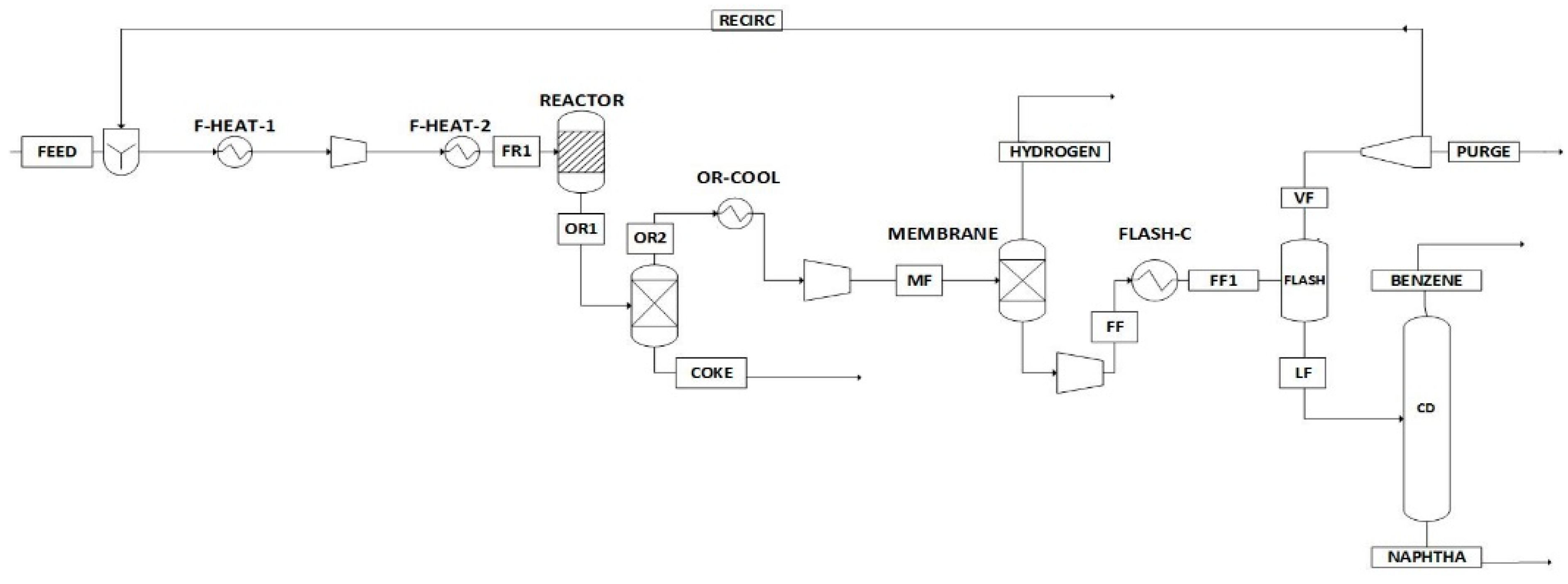
The process flowsheet developed in this work to produce benzene from shale gas is based on the methane dehydroaromatization reaction path. The best operating conditions reported in the literature are considered. In the flowsheet, a fresh stream of methane is fed into the process, mixed with a methane-rich recycle stream; the mixture is heated to 800 °C and sent to the DMA reactor, which operates at 800 °C and 1 atm [30]. The product of the reaction is sent to a membrane separation system to remove the hydrogen produced [39]. The remaining gases are cooled and compressed before being sent to a flash separator to recover the unreacted methane as a top product. Part of this stream is purged, and the rest is returned to the reactor. The liquid obtained in the flash unit is sent to a distillation column, which purifies the benzene product, with naphthalene obtained at the bottom of the column as a byproduct. The process flowsheet is shown in Figure 1.
The Aspen Plus process simulator was used for the technical analysis of the flowsheet. For the MDA reactor, the use of the Mo/HZSM-5 catalyst was assumed. Although no kinetic model was found for this reaction, the overall catalyst performance for benzene selectivity and methane conversion reported by Xu et al. [30] provided the basis for modeling the unit as an RStoich reactor. The catalyst performance includes the effect of a regeneration cycle using H2, which also limits the amount of CO and CO2 produced with respect to an oxidative option. The membrane unit was modeled as a separation module using the data reported by De vos [39]. As for coke, it was simulated as carbon [11,17]. Distillation columns were simulated using the Radfrac module, with 36 stages, condenser and reboiler temperatures of 160 °C and 305 °C, a pressure condenser of 10 atm, and a pressure drop of 0.1 atm/stage.
The initial results, based on a feed flowrate of 1000 kmol/h of purified shale gas, are reported in Table 1. The temperature and pressure conditions for each stream of the flowsheet are included. It can be observed that the benzene product is obtained with a purity of 97%, and that the formation of hydrogen and naphthalene byproducts amounts to 1564 and 16.5 kmol/h, respectively. The recirculation stream to the reactor contains 99% of methane.
Two major variables that affect the performance of the process are the operating conditions of the reactor and the flash separation unit. A sensitivity analysis was then carried out in order to assess the effect of such variables in the flowsheet and detect the best operating conditions. The initial expectation for the reactor is that that higher temperatures favor the reaction conversion, while lower pressures promote the reaction towards the benzene product. For the flash unit, the use of lower temperatures and higher pressures favors the recovery of benzene. We proceeded to analyze the effect of temperature and pressure of these units on the technical and economic performance of the process.
For the economic analysis, the return on investment (ROI) was used to assess the process profitability [40]:
A tax rate of 30% and working capital investment of 15% of the total capital investment were assumed, with a 10-year linear depreciation rate, an operating time of 7920 h/year, and a salvage value of 10% of the capital investment.
For the estimation of the process investment, the report by DuBose [41] for a gas-to aromatics process was taken as a basis. For a process with a capacity of 50,000 barrels of liquid product, which includes a stage of catalyst regeneration, the investment was reported as 1.82 billion dollars. Using the 6/10 rule, we adjusted this value for our base benzene production of 100 kmol/h as 231.7 $MM.
The price of benzene was set at $1025/T. Prices for naphthalene and hydrogen obtained as byproducts were taken as $552/T and $2/kg, respectively. The purchase price of purified shale gas was set at $3.5/KSCF. Prices for heating utilities, cooling utilities, and power consumption were taken as $4/MMBTU, $1.94/MMBTU, and $0.05/KWh [6,40].
The analysis was carried out using the following constraints:
- Minimum reaction temperature of 700 °C. Using a lower temperature leads to a significant drop in conversion [30].
- Maximum reaction temperature of 800 °C. This value is the highest operating temperature of the reactor [30].
- Minimum reaction pressure of 0.3 bar. Set as an operation limit.
- Maximum reaction pressure of 2.026 bar. Higher pressures decrease conversion values significantly.
- Minimum temperature of the flash unit of 20 °C. Lower temperatures would require the use of refrigerants.
- Minimum flash pressure of 10 bar. Lower pressures lead to poor benzene recoveries.
- Maximum reaction pressure of 20 bar. Benzene recovery does not improve significantly at higher pressures.
It should be noted that the limits on temperature considered here reflect the reported behavior of the Mo/HZSM-5 catalyst for the DMA process. While high temperatures are desired to provide higher rates of reaction, temperatures above 800 °C cause catalyst deactivation due to coke formation.
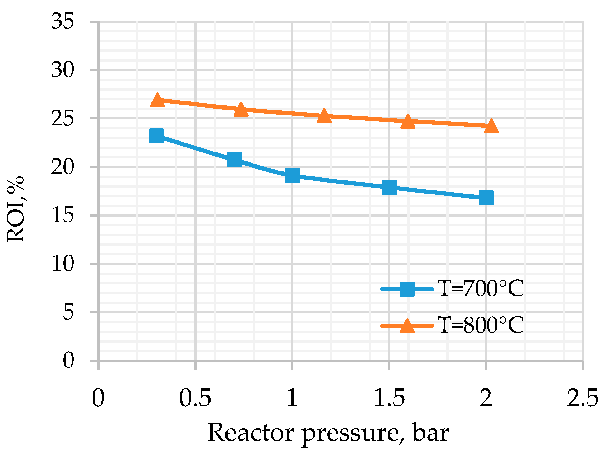
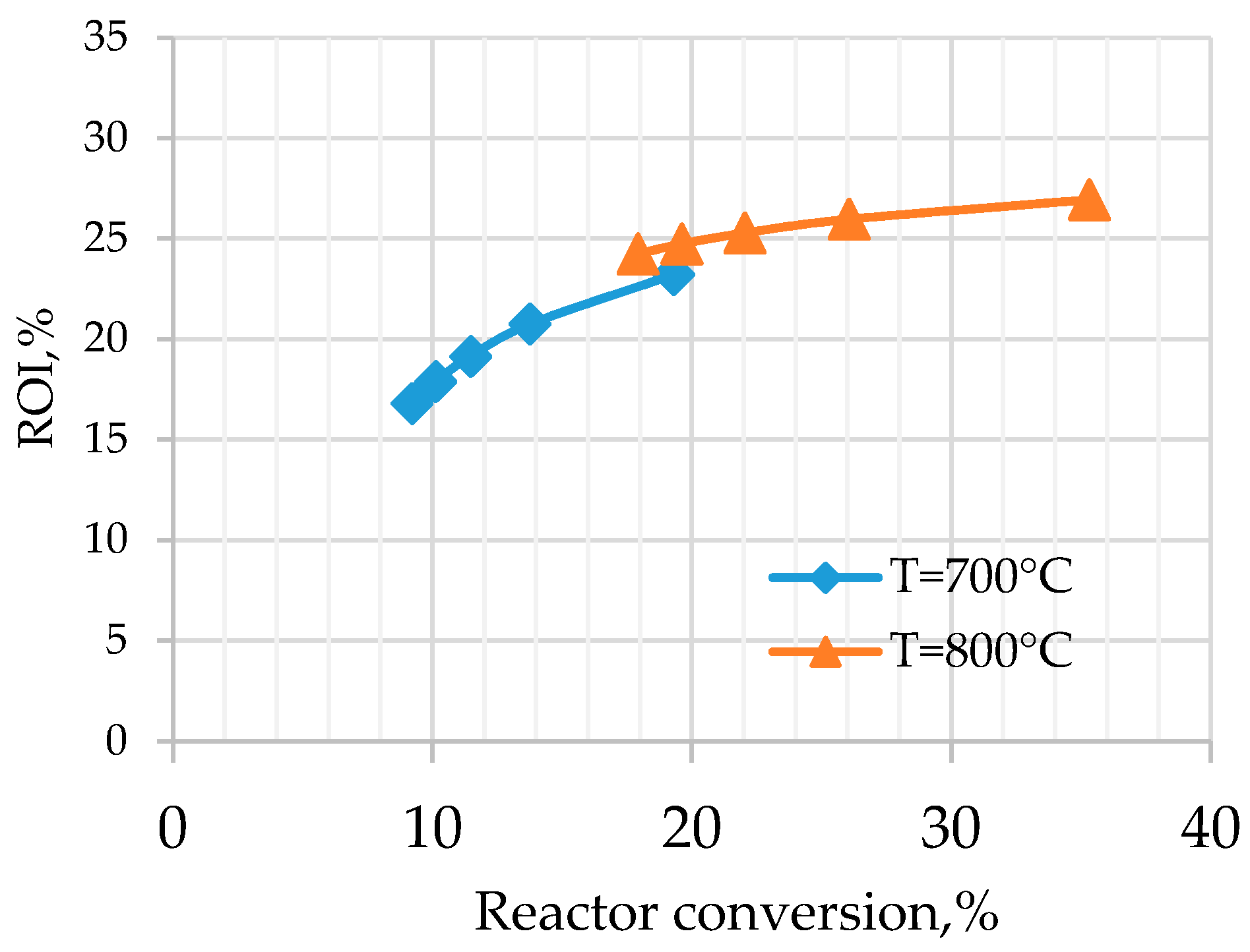
Figure 2 shows the results obtained from the sensitivity analysis on the reactor operating conditions. The effect of the two limits on the reactor temperature and of the operating pressure is reported. The highest ROI value of 27% was obtained when the operating conditions for the reactor were 800 °C and 0.3 bar, conditions under which the reaction conversion was 35% (see Figure 3).
As far as the flash unit, the best operating conditions were 20 °C and 10 bar. It was expected that, using a lower temperature and a higher pressure, conditions that promote the maximum recovery of benzene would benefit the process profitability, but the operating and fixed costs adversely affected the process economics.
With the best conditions detected for the reactor and flash operation unit, the total annual cost was estimated as 55.2 $MM/year. The ROI estimated for the benzene process was 27%, which indicates that the process could provide an attractive option from an economic point of view.
3.1. Effect of Energy Integration
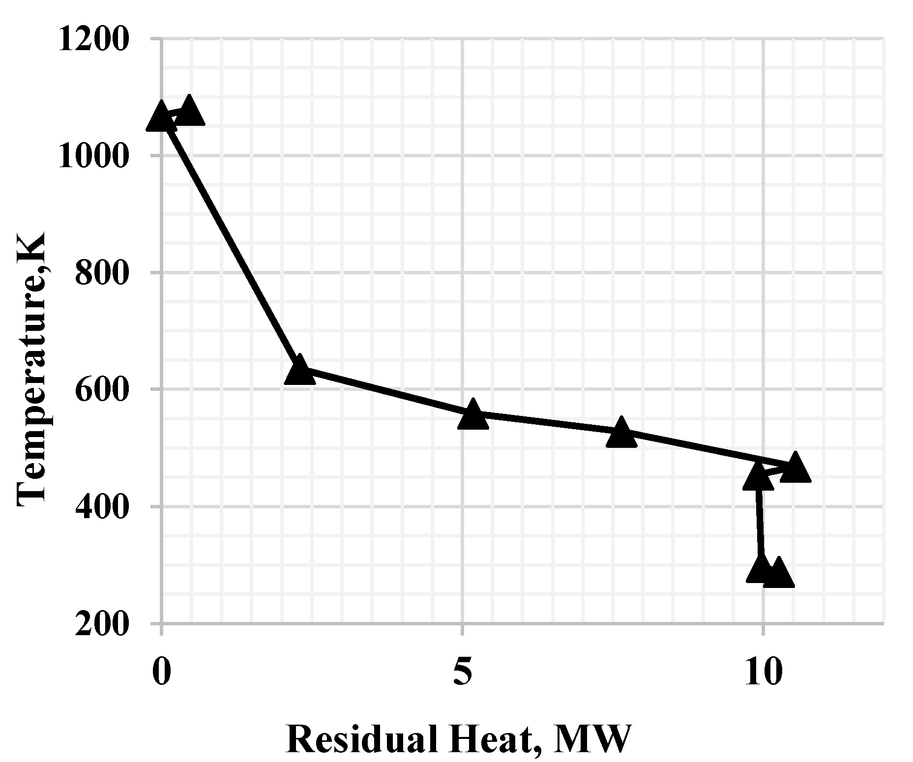
Given that heating and cooling utilities provide a significant share of the process operating cost, an analysis on the effect of energy integration was conducted. Two heaters and three coolers are part of the process, and their heat duties can be reduced by energy integration. The stream data given in Table 2 was used for the analysis; heat duties associated with the operation of distillation units were not included. A pinch analysis was first developed to obtain targets for heat integration. Based on a minimum driving force of 10 K, the grand composite curve shown in Figure 4 was obtained. The target values for energy integration show that the heating and cooling utilities could be reduced to 31.08 and 11.73 MW, which amount to reductions of 53.7 and 75.3%, respectively, as shown in Figure 5. Under these conditions, an increase of 1.7% in the ROI would be observed.
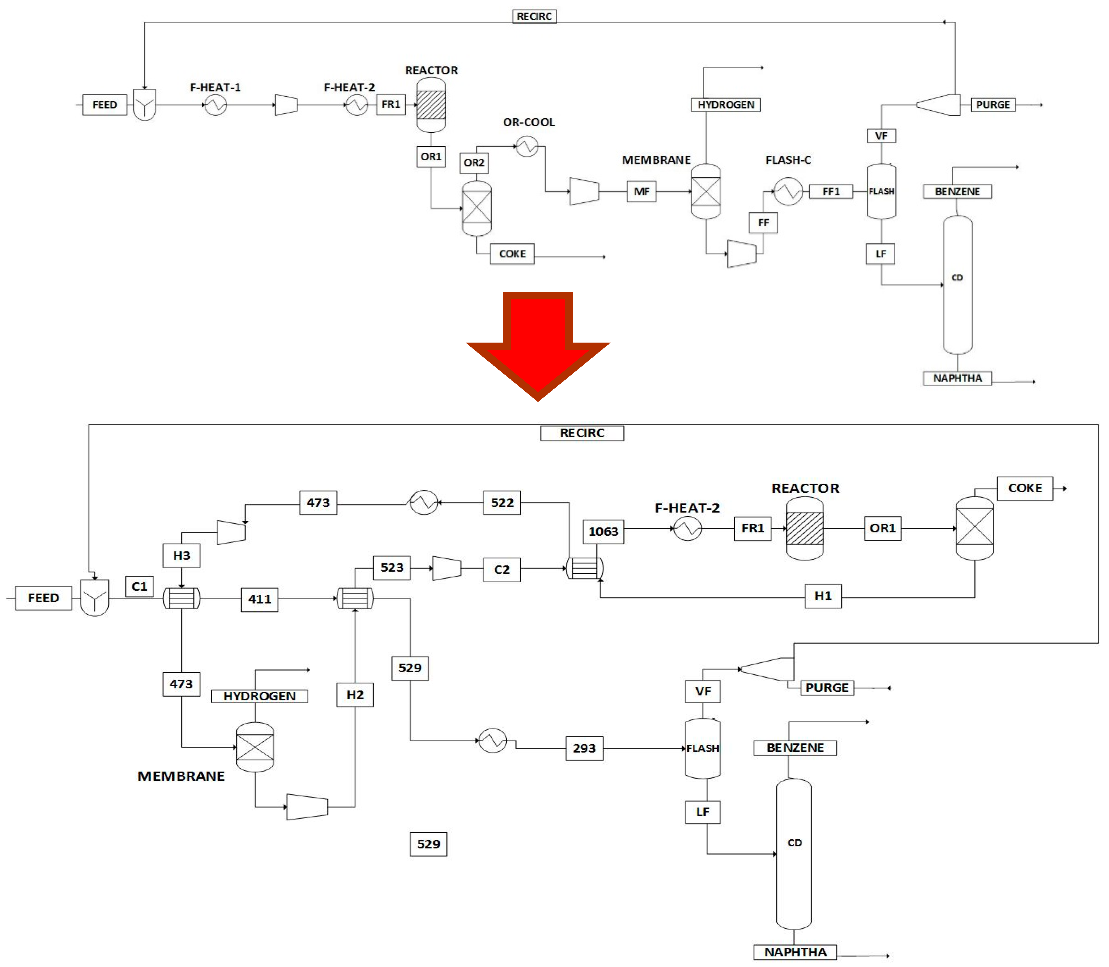
A heat exchanger network that meets the minimum utility requirements was then designed, and the resulting network shown in Figure 6 was obtained. Three heat exchangers are needed for the implementation of the integration network, and the temperatures for each stream after each exchanger are indicated. The duty of the feed to the reactor is met by integration with the feed stream to the membrane followed by the permeate stream from the membrane. The other exchanger is used to preheat the feed to the reactor with the output stream from the same unit.
Given the fairly simple structure of the heat exchanger network, its implementation provides an incentive to achieve a more profitable process.
3.2. Environmental Assessment
CO2 emissions were calculated to assess the environmental impact of the benzene process. CO2 equivalent values due to electricity were calculated using a factor of 0.73 Tons of CO2/MWh [42]. The emissions from heating utilities were estimated using the Environmental Protection Agency (EPA) method for stationary combustion sources [43]. For a given amount of fuel used for combustion, F, the calculation for CO2 emissions (kg/day) were conducted with the following relationship:
where F is in standard cubic feet/day, HCFuel is the heat content of the fuel, and CFuel is the coefficient for fuel carbon content. Natural gas was assumed as the fuel, with a heat content of 1029 BTU/SCF and a carbon content coefficient of 14.47 kg of carbon/MMBTU.
Table 3 shows the details of the CO2 emissions estimated for the process. The effect of energy integration is also included. It can be observed that the implementation of the heat integration network promotes a reduction of 16.3% on CO2 emissions, which provides another incentive for its consideration.
4. Conclusions
A process for the production of benzene from shale gas using direct methane aromatization technology as a basis has been designed. Aided by the use of the Aspen Plus process simulator, the developed flowsheet was shown to be technically effective to carry out the required transformation. The two major parts of the flowsheet that affect the process profitability are the reactor and the flash units, and the best operating conditions for such units were detected. The results show high potential of profitability for this technology. It was also shown that heat integration can be worth consideration, given the simple structure of the integration network and its impact on both process economics and environmental implications.
Acknowledgments
Support from the National Council for Science and Technology, CONACYT, Mexico, for six-month stays of S.I. Pérez-Uresti and J.M. Adrián-Mendiola at Texas A&M University is gratefully acknowledged.
Author Contributions
Salvador I. Pérez-Uresti and Jorge M. Adrián-Mendiola carried out the design and simulations of the process as part of their Master of Science theses, under the supervision of the other two authors. Mahmoud M. El-Halwagi and Arturo Jiménez-Gutiérrez prepared the manuscript.
Conflicts of Interest
The authors declare no conflict of interest.
Abbreviations
The following abbreviations are used in this manuscript
| DMA | Direct methane aromatization |
| ROI | Return on investment |
References
- Bullin, K.A.; Krouskop, P.E. Compositional variety complicates processing plans for US shale gas. Oil Gas J. 2009, 107, 50–55. [Google Scholar]
- Natesakhawat, S.; Means, N.C.; Howard, B.H.; Smith, M.; Abdelsayed, V.; Nicot, J.P.; Scanlon, B. Water Use for Shale-gas Production in Texas, U.S. Environ. Sci. Technol. 2012, 46, 3580–3586. [Google Scholar]
- U.S. Energy Information Administration. Technically Recoverable Shale Oil and Shale Gas: An Assessment of 137 Shale Formation in 41 Countries Outside the United States; U.S. Energy Information Administration: Washington, DC, USA, 2013.
- U.S. Energy Information Administration. Shale Gas Proved Reserves; U.S. Energy Information Administration: Washington, DC, USA, 2015. Available online: http://www.eia.gov/dnav/ng/ng_enr_shalegas_dcu_nus_a.htm (accessed on 10 July 2015).
- Al-Douri, A.; Sengupta, D.; El-Halwagi, M.M. Shale gas monetization: A review of downstream processing to chemicals and fuels. J. Nat. Gas Sci. Eng. 2017, 45, 436–455. [Google Scholar] [CrossRef]
- Ehlinger, V.; Gabriel, K.; Noureldin, M.; El-Halgawi, M.M. Process desing and integration of shale gas to methanol. ACS Sustain. Chem. Eng. 2014, 2, 30–37. [Google Scholar] [CrossRef]
- Martínez, Y.D.; Jiménez-Gutiérrez, A.; Linke, P.; Gabriel, K.J.; Noureldin, M.M.B.; El-Halwagi, M.M. Water ane energy issues in gas-to-liquid processes: Assessment and Integration of different reforming alternatives. ACS Sustain. Chem. Eng. 2014, 2, 216–225. [Google Scholar] [CrossRef]
- Julián-Durán, L.M.; Ortiz-Espinoza, A.P.; El-Halwagi, M.M.; Jiménez-Gutiérrez, A. Techno-economic assessment and environmental impact of shale gas alternatives to methanol. ACS Sustain. Chem. Eng. 2014, 2, 2338–2344. [Google Scholar] [CrossRef]
- Jasper, S.; El-Halwagi, M.M. A Techno-Economic Comparison between Two Methanol-to-Propylene Processes. Processes 2015, 3, 684–698. [Google Scholar] [CrossRef]
- Plotkin, J.S. Benzene’s Unusual Supply–Demand Dilemma. Ind. Chem. Eng. 2015. Available online: http://www.acs.org/content/acs/en (accessed on 10 January 2017).
- Spivey, J.J.; Hutchings, G. Catalytic aromatization of methane. Chem. Soc. Rev. 2014, 43, 792–803. [Google Scholar] [CrossRef] [PubMed]
- Wang, L.; Tao, L.; Xie, M.; Xu, G. Dehydrogenation and aromatization of methane under non-oxidizing conditions. Catal. Lett. 1993, 21, 53–67. [Google Scholar] [CrossRef]
- Xu, Y.; Lin, L. Recent advances in methane dehydro-aromatization over transition metal ion-modified zeolite catalysts under non-oxidative conditions. Appl. Catal. A 1999, 188, 53–67. [Google Scholar] [CrossRef]
- Zeng, J.L.; Xiong, Z.T.; Zhang, H.B.; Lin, G.D.; Tsai, K.R. Nonoxidative dehydrogenation and aromatization of methane over W/HZSM-5-based catalysts. Catal. Lett. 1998, 53, 119–124. [Google Scholar] [CrossRef]
- Iliuta, M.C.; Iliuta, I.; Grandjean, B.P.A.; Larachi, F. Kinetics of Methane Nonoxidative Aromatization over Ru-Mo/ HZSM-5 Catalyst. Ind. Eng. Chem. Res. 2003, 42, 3203–3209. [Google Scholar] [CrossRef]
- Wang, D.Y.; Kan, Q.B.; Xu, N.; Wu, P.; Wu, T.H. Study on methane aromatization over MoO3/HMCM-49 catalyst. Catal. Today 2004, 93–95, 75–80. [Google Scholar] [CrossRef]
- Song, Y.; Xu, Y.; Suzuki, Y.; Nakagome, H.; Zhang, Z.G. A clue to exploration of the pathway of coke formation on Mo/HZSM-5 catalyst in the non-oxidative methane dehydroaromatization at 1073 K. Appl. Catal. A 2014, 482, 387–396. [Google Scholar] [CrossRef]
- Karakaya, C.; Zhu, H.; Kee, R.J. Kinetic modeling of methane dehydroaromatization chemistry on Mo/Zeolite catalysts in packed-bed reactors. Chem. Eng. Sci. 2015, 123, 474–486. [Google Scholar] [CrossRef]
- Zhang, C.L.; Li, S.; Yuan, Y.; Zhang, W.X.; Wu, T.H.; Lin, L.W. Aromatization of methane in the absence of oxygen over Mo-based catalysts supported on different types of zeolites. Catal. Lett. 1998, 56, 207–213. [Google Scholar] [CrossRef]
- Ding, W.P.; Meitzner, G.D.; Iglesia, E. The Effects of Silanation of External Acid Sites on the Structure and Catalytic Behavior of Mo/H–ZSM5. J. Catal. 2002, 206, 14–22. [Google Scholar] [CrossRef]
- Burns, S.; Hargreaves, J.S.J.; Pal, P.; Parida, K.M.; Parija, S. The effect of dopants on the activity of MoO3/ZSM-5 catalysts for the dehydroaromatisation of methane. Catal. Today 2006, 114, 383–387. [Google Scholar] [CrossRef]
- Li, Y.; Su, L.; Wang, H.; Liu, H.; Shen, W.; Bao, X.; Xu, Y. Combined single-pass conversion of methane via oxidative coupling and dehydroaromatization. Catal. Lett. 2003, 89, 275–279. [Google Scholar] [CrossRef]
- Liu, B.; Yang, Y.; Sayari, A. Non-oxidative dehydroaromatization of methane over Ga-promoted Mo/HZSM-5-based catalysts. Appl. Catal. A 2001, 214, 95–102. [Google Scholar] [CrossRef]
- Skutil, K.; Taniewski, M. Some technological aspects of methane aromatization (direct and via oxidative coupling). Fuel Process. Technol. 2006, 87, 511–521. [Google Scholar] [CrossRef]
- Xu, Y.; Lua, J.; Wang, J.; Suzuki, Y.; Zhang, Z.G. The catalytic stability of Mo/HZSM-5 in methane dehydroaromatization at severe and periodic CH4–H2 switch operating conditions. Chem. Eng. J. 2011, 168, 390–402. [Google Scholar] [CrossRef]
- Gimeno, M.P.; Soler, J.; Herguido, J.; Menendez, M. Counteracting Catalyst Deactivation in Methane Aromatization with a Two Zone Fluidized Bed Reactor. Ind. Eng. Chem. Res. 2010, 49, 996–1000. [Google Scholar] [CrossRef]
- Skutil, K.; Taniewski, M. Indirect methane aromatization via oxidative coupling, products separation and aromatization steps. Fuel Process. Technol. 2007, 88, 877–882. [Google Scholar] [CrossRef]
- Cook, B.; Mousko, D.; Hoelderich, W.; Zennaro, R. Conversion of methane to aromatics over Mo2C/ZSM-5 catalyst in different reactor types. Appl. Catal. A 2009, 365, 34–41. [Google Scholar] [CrossRef]
- Natesakhawat, S.; Means, N.C.; Howard, B.H.; Smith, M.; Abdelsayed, V.; Baltrus, J.P.; Cheng, Y.; Lekse, J.W.; Link, D.; Morreale, B.D. Improved benzene production from methane dehydroaromatization over Mo/HZSM-5 catalysts via hydrogen-permselective palladium membrane reactors. Catal. Sci. Technol. 2015, 5, 5023–5036. [Google Scholar] [CrossRef]
- Xu, Y.; Lua, J.; Suzukia, Y.; Zhanga, Z.G.; Ma, H.; Yamamotoca, Y. Performance of a binder-free, spherical-shaped Mo/HZSM-5 catalyst in the non-oxidative CH4 dehydroaromatization in fixed- and fluidized-bed reactors under periodic CH4–H2 switch operation. Chem. Eng. Process. 2013, 72, 90–102. [Google Scholar] [CrossRef]
- Yamada, S.; Yamada, T.; Ogawa, Y.; Akiyama, H.; Hatagishi, T. Catalyst for Aromatization of Lower Hydrocarbons and Process for Production of Aromatic Compounds. U.S. Patent US 8,278,237 B2, 2 October 2012. [Google Scholar]
- Menéndez, M.S.; Huerta, J.H.; Téllez, C.; Soler, J.; Gimeno, M.P. Method for obtaining aromatic hydrocarbons from methane. U.S. Patent US 8,697,926 B2, 15 April 2014. [Google Scholar]
- Chen, J.Q.; Vora, B.V.; Pujadó, P.R.; Fuglerud, T. Most Recent developments in ethylene and propylene production from natural gas using the UOP/Hydro MTO process. In Studies in Surface Science and Catalysis; Bao, X., Xu, Y., Eds.; Elsevier: Amsterdam, The Netherlands, 2004; Volume 147, pp. 1–6. [Google Scholar]
- Zhu, P.; Yang, G.; Sun, J.; Fan, R.; Zhang, P.; Yoneyama, Y.; Tsubaki, N. A hollow Mo/HZSM-5 zeolite capsule catalyst: Preparation and enhanced catalytic properties in methane dehydroaromatization. J. Mater. Chem. A 2017, 5, 8599–8607. [Google Scholar] [CrossRef]
- Kosinov, N.; Coumans, F.J.A.G.; Li, G.; Uslamin, E.; Mezari, B.; Wijpkema, A.S.G.; Pidko, E.A.; Hensen, E.J.M. Stable Mo/HZSM-5 methane dehydroaromatization catalysts optimized for high-temperature calcination-regeneration. J. Catal. 2017, 346, 125–133. [Google Scholar] [CrossRef]
- Kosinov, N.; Coumans, F.J.A.G.; Uslamin, E.; Kapteijn, F.; Hensen, E.J.M. Selective coke combustion of oxygen pulsing during Mo/ZSM-5-catalized methane dehydroaromatization. Angew. Chem. Int. Ed. 2016, 55, 15086–15090. [Google Scholar] [CrossRef] [PubMed]
- Cao, Z.; Jiang, H.; Luo, H.; Baumann, S.; Meulenberg, W.A.; Assmann, J.; Mleczko, L.; Liu, Y.; Caro, J. Nautral gas to fuels and chemicals: Improved methane aromatization in an oxygen-permeable membrane reactor. Angew. Chem. 2013, 125, 14039–14042. [Google Scholar] [CrossRef]
- Morejudo, S.H.; Zanón, R.; Escolástico, S.; Yuste-Tirados, I.; Malerod-Fjeld, H.; Vestre, P.K.; Coors, W.G.; Martínez, A.; Norby, T.; Serra, J.M.; et al. Aromatic conversion of methane to aromatics in a catalytic co-aionic membrane reactor. Science 2016, 353, 563–566. [Google Scholar] [CrossRef] [PubMed]
- De Vos, R.M.; Verweij, H. Improved performance of silica membranes for gas separation. J. Memb. Sci. 1998, 143, 37–51. [Google Scholar] [CrossRef]
- El-Halwagi, M.M. Sustainable Design through Process Integration: Fundamentals Applications to Industrial Pollution Prevention, Resource Conservation, and Profitability Enhancement; Butterworth-Heinemann: Oxford, UK, 2012. [Google Scholar]
- DuBose, B. IRPC’15: New gas-to-aromatic technology offers hugh potential—GTC. 2015. Available online: http://www.hydrocarbonprocessing.com/conference-news/2015/06/irpc-15-new-gas-to-aromatics-technology-offers-huge-potential-gtc (accessed on 24 February 2017).
- U.S. Energy Information Administration. Electricity Emission Factors, Voluntary Reporting of Greenhouse Gases Program; U.S. Energy Information Administration: Washington, DC, USA, 2014.
- U.S. Environmental Protection Agency. Direct Emissions from Stationary Combustion Sources; EPA430-K-08-003; Environmental Protection Agency: Washington, DC, USA, 2008.
Figure 1.
Flowsheet for the direct methane aromatization-based benzene process.

Figure 2.
Sensitivity analysis for the reactor conditions.

Figure 3.
Effect of reactor conversion on return on investment values.

Figure 4.
Grand Composite Curve for the process at 1073 K.

Figure 5.
Effect of energy integration on heating and cooling requirements.
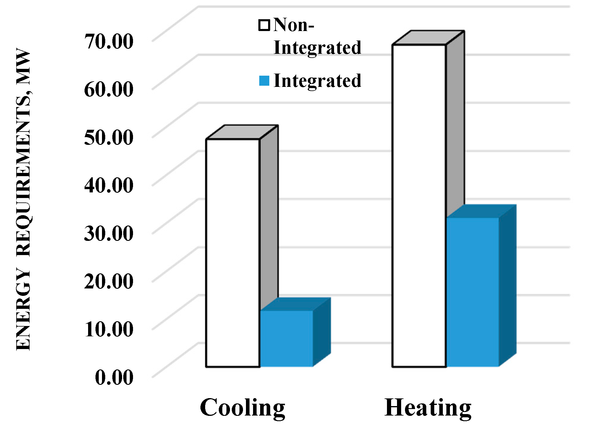
Figure 6.
Heat exchanger network implemented for the benzene process.


Table 1.
Key stream data for the benzene process.
| Stream Label | Methane | H2 | Benzene | Toluene | Naphthalene | Coke | Total (kmol/h) | P (atm) | T (°C) |
|---|---|---|---|---|---|---|---|---|---|
| Feed | 1000 | 0 | 0 | 0 | 0 | 0 | 1000 | 1 | 25 |
| FR1 | 2748 | 0 | 18.2 | 0.17 | 0 | 0 | 2767 | 0.3 | 800 |
| OR1 | 1778 | 1564 | 118 | 2.53 | 16.5 | 187 | 3666 | 0.3 | 800 |
| COKE | 0 | 0 | 0 | 0 | 0 | 187 | 187 | 1 | 800 |
| OR2 | 1778 | 1564 | 118 | 2.53 | 16.5 | 0 | 3479 | 0.3 | 800 |
| MF | 1778 | 1564 | 118 | 2.53 | 16.5 | 0 | 3479 | 2 | 200 |
| Hydrogen | 0 | 1564 | 0 | 0 | 0 | 0 | 1564 | 1 | 200 |
| FF | 1778 | 0 | 118 | 2.53 | 16.5 | 0 | 1915 | 10 | 20 |
| VF | 1775 | 0 | 18.5 | 0.17 | 0 | 0 | 1794 | 10 | 20 |
| LF | 3 | 0 | 100 | 2.3 | 16.49 | 0 | 121.79 | 10 | 20 |
| PURGE | 26.6 | 0 | 0.27 | 0 | 0 | 0 | 26.87 | 10 | 20 |
| RECIRC | 1748 | 0 | 18.25 | 0.17 | 0 | 0 | 1766 | 1 | 15 |
| BENZENE | 3.09 | 0 | 99 | 0.23 | 0 | 0 | 102.3 | 10 | 160 |
| NAPHTHA | 0 | 0 | 1 | 2.11 | 16.49 | 0 | 19.6 | 10 | 308 |
Flows given in kmol/h. Labels for the streams refer to Figure 1.
Table 2.
Process data for heat integration.
| Heat Exchanger Tag | Description | Supply Temperature (K) | Target Temperature (K) | Heat Duty (MW) |
|---|---|---|---|---|
| OR-COOL (H1) | Cooler output reactor | 1073 | 473 | 30.83 |
| FLAS-C (H2) | Cooler output membrane | 639.7 | 293 | 11.33 |
| M-COOL (H3) | Cooler feed to membrane | 563.6 | 473 | 3.86 |
| F-HEAT-1 (C1) | Heater feed to reactor | 291.4 | 523 | 7.44 |
| F-HEAT-2 (C2) | Heater feed to reactor | 449.4 | 1073 | 28.74 |
Table 3.
CO2 process emissions (105 T/y).
| Source | Original Process | Integrated Process |
|---|---|---|
| Streams | 1.54 | 1.54 |
| Burning Fuels | 0.96 | 0.44 |
| Electricity | 0.68 | 0.68 |
| Total | 3.19 | 2.67 |
© 2017 by the authors. Licensee MDPI, Basel, Switzerland. This article is an open access article distributed under the terms and conditions of the Creative Commons Attribution (CC BY) license (http://creativecommons.org/licenses/by/4.0/).
Share and Cite
MDPI and ACS Style
Pérez-Uresti, S.I.; Adrián-Mendiola, J.M.; El-Halwagi, M.M.; Jiménez-Gutiérrez, A. Techno-Economic Assessment of Benzene Production from Shale Gas. Processes 2017, 5, 33. https://doi.org/10.3390/pr5030033
AMA Style
Pérez-Uresti SI, Adrián-Mendiola JM, El-Halwagi MM, Jiménez-Gutiérrez A. Techno-Economic Assessment of Benzene Production from Shale Gas. Processes. 2017; 5(3):33. https://doi.org/10.3390/pr5030033
Chicago/Turabian StylePérez-Uresti, Salvador I., Jorge M. Adrián-Mendiola, Mahmoud M. El-Halwagi, and Arturo Jiménez-Gutiérrez. 2017. "Techno-Economic Assessment of Benzene Production from Shale Gas" Processes 5, no. 3: 33. https://doi.org/10.3390/pr5030033
Note that from the first issue of 2016, this journal uses article numbers instead of page numbers. See further details here.