Selected Phenomena of the In-Mold Nodularization Process of Cast Iron That Influence the Quality of Cast Machine Parts


Department of Foundry Engineering, Silesian University of Technology, Towarowa 7 str., 44-100 Gliwice, Poland
*
Author to whom correspondence should be addressed.
Processes 2017, 5(4), 68; https://doi.org/10.3390/pr5040068
Submission received: 26 September 2017
/
Revised: 18 October 2017
/
Accepted: 1 November 2017
/
Published: 6 November 2017
Abstract
:This paper discusses a problem connected with the production process of ductile iron castings made using the in-mold method. The study results are presented showing that this method compromises the quality of the cast machine parts and of the equipment itself. Specifics of the nodularization process using the in-mold method do not provide the proper conditions for removal of chemical reaction products to the slag, i.e., the products stay in the mold cavity and they also decrease the quality of the casting. In this work, corrosion-type defects were diagnosed mostly on the surface of the casting and some compounds in the near-surface layer—i.e., fayalite (Fe2SiO4) and forsterite (Mg2SiO4)—which cause discontinuities in the metal matrix. The results presented here were selected based on experimental melts of ductile iron. The elements of the mold used in this study, the shape of the mixing chamber, charge materials, method of melting, temperature of liquid metal, etc. were directly related to the production conditions. An analysis was conducted of the chemical composition using a Leco GDS500A spectrometer and a carbon and sulfur Leco CS125 analyzer. Metallographic examinations were conducted using a Phenom-ProX scanning electron microscope with an EDS system.
1. Introduction
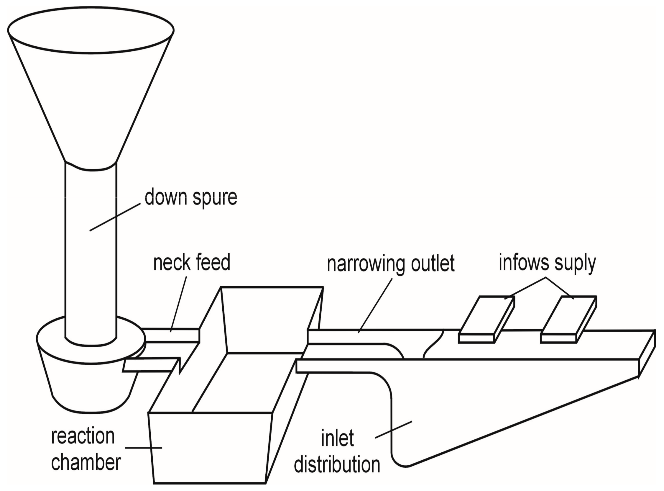
The aim of the article was to show the problems that arise from using the in-mold spheroidysation method. The work describes intermetallic phases formation in nodular cast irons. The presented results are reproducible. There are several methods of conducting the cast iron nodularization process, of which the most common are the: cored wire method, bell method, sandwich, and tundisch. Currently, one of the most widespread methods for the production of castings from ductile and vermicular iron is the nodularization process in mold. The advantages of this method have undoubtedly resulted in its wide range of applications, particularly on automated casting lines. The mold method is considered to be ecological as the process does not have a negative effect on the environment due to the nodularization treatment in a closed mold equipped with a reaction chamber. This way of conducting the process causes a significant reduction in the amount of gaseous products passing into the environment. Moreover, the output of the nodulizing mixture increases, which then lowers production costs. At work, [1] presented a way of grey cast iron production with vermicular graphite based on the in-mold method. This type of cast iron requires knowledge about the cast iron metallurgical process because of the very restrictive amount of residual magnesium at 0.02% (for ductile iron it is 0.04–0.060% Mg). The authors [1], suggested to add sulfur compounds into the liquid metal—e.g., Fe2S—in order to decrease the amount of magnesium to the required content of 0.02% Mg. Cast iron with vermicular precipitates of graphite can be obtained as a result of this process. Discussion issues are the compounds that form during the reaction of liquid metal with the magnesium mixture in a reaction chamber during casting formation; here we can distinguish magnesium sulfide (MgS), as was discussed [2]; cerium sulfide CeS, which [3] described; and the compounds that were described [4], namely fayalite-Fe2SiO4 and forsterite-Mg2SiO4. The density of magnesium sulfide is 2.68 g/cm3; of cerium sulfide it is 5.9 g/cm3; of fayalite it is 4.3 g/cm3; and of forsterite it is 3.21 g/cm3. In comparison to the average density of cast iron, which is 7.1–7.2 g/cm3, the above compounds have a lower density, so they flow upward. If the secondary treatment of liquid metal (the nodularization process) is carried out in a ladle, the said compounds flow to the surface of the metal in the ladle. Then they are removed with the slag from the surface of the liquid metal. Finally, the alloy is poured into molds. Its metallurgical quality is high and the probability of the appearance of sulfide inclusions or of fayalite and forsterite is slight. This is different for the in-mold nodularization method. The compounds flow into the mold cavity and stay there. They form inclusions on the surface layer of the casting, which decreases the quality of the product. The casting construction does not always allow for these impurities to flow into the risers. Mohs scale of hardness for fayalite is 6.5 and 7 for forsterite. A typical view of the gating system for the in-mold process is shown in Figure 1.
2. Experimental Details
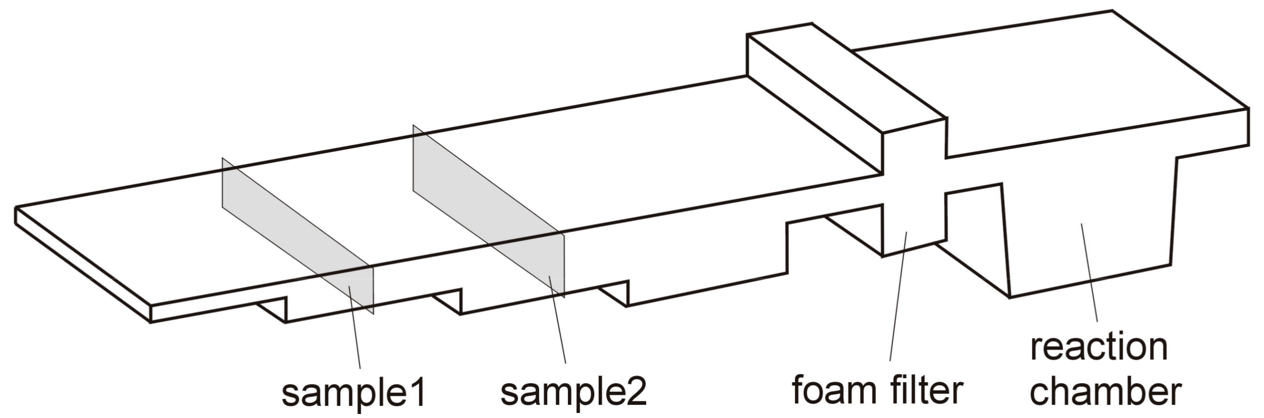
Experimental studies were conducted in laboratory conditions. Experimental melts were conducted using an induction furnace powered with medium frequency voltage. The furnace capacity was 25 kg. The charge material used for the melt consisted of steel scrap with a low amount of sulfur, carburizer Ranco 9905, FeSi75. The type of cast iron used in the test and its manufacturing method qualify this alloy as a synthetic ductile iron as described [5]. The nodularization process was conducted directly in the reaction chamber in mold (see Figure 1). The ceramic foam filter was placed behind the reaction chamber. The mold was prepared of molding sand consisting of silica sand with bentonite and water. The mold technology was accordance with industrial partner recommendation. During the experiment, magnesium mixture FeSiMg5RE was used, which is applied in the mass production of castings with the in-mold method. Chemical composition of magnesium master alloy was as follows: 40–47% Si, 4.5–5.5% Mg, 0.5–1% Ce, 0.8–1.2 % RE, 1.5–2.5% Ca, 1% Al, 0.5% Ti. The pieces of magnesium master alloy had size between 5 and 10 mm. It is characterized by a reduced magnesium content and a higher amount of rare earth elements, including cerium and other lanthanides; it was used for nodularization in research [6]. Chemical composition of metal charge was as follows: 0.08% C, 0.001% Si, 0.04% Mn, 0.004% Cu, 0.046% Al, 0.006% S, 0.016% P. The metal charge in the form of steel scrap was cleaned of corrosion products, dried, and loaded into the working place of the furnace so that an empty cavity was created into which the calculated amount of Ranco 9905 carburizer was introduced. At a temperature of 1417 °C in the furnace the slag was removed from the surface of the liquid alloy and a sample for chemical composition analysis was taken. Then the molten alloy was poured into a preheated casting ladle (a gas burner was used to heat the casting ladle). The liquid metal in the casting ladle was used to fill a previously prepared mold cavity, where a weighted amount of FeSiMg5RE nodulizer was applied into the reaction chamber. In the next step the chemical composition analysis of the obtained casting was conducted using a Leco CS125 analyzer of carbon and sulfur. Also, metallographic examinations using a Phenom-ProX scanning electron microscope with an Energy-Dispersive X-ray Spectroscopy (EDS) system were performed. The metallographic examinations and chemical composition analysis were conducted on samples cut from the experimental casting. The scheme of the casting part with marked location from which metallographic samples were taken is presented in Figure 2.
3. Results
3.1. Chemical Composition Analysis
Table 1 presents the chemical composition of cast iron (1—for a sample taken from the furnace after the metallurgical process (carburizing and inoculation process; 2—a sample cut from the casting). The content of carbon and sulfur was corrected based on results obtained from the Leco CS125 analyzer.
3.2. Metallographic Examinations
Figure 2, Figure 3, Figure 4 and Figure 5 present the results of metallographic examinations of the analyzed experimental casting. The areas visible at the metallographic section, particularly in the surface layer of the casting, form the oxide layer resulting from corrosion phenomena that occur on the surface of the casting.
Figure 3 shows the surface layer of the casting with the harmful precipitate of fayalite. On the left side of this inclusion, marked with the number 2, a layer of corrosion products is noticeable, while on the right side the microstructure of the casting dark precipitates of nodular graphite can be observed. Below are the results of point analysis obtained based on the EDS system and on the Phenom ProX scanning electron microscope. Peaks of elements of the analyzed precipitate which are seen on the graph correspond to the chemical composition of fayalite (Fe2SiO4). Due to the difficulty of preparing the sample, it was not possible to conduct additional X-ray diffraction studies for the present area at this stage of research in order to confirm the result.
The next unfavorable inclusion observed in the experimental casting is forsterite (Mg2SiO4). A view of this precipitate in the analyzed microstructure is presented in Figure 5.
The observed inclusions shown in Figure 5 correspond to the Mg2SiO4 chemical compound classified as forsterite. The amount of these inclusions identified in the analyzed casting is lower than the fayalite precipitate (Fe2SiO4). Figure 5 clearly shows that this inclusion has higher hardness than the metal matrix, as evidenced by greater height of the forsterite precipitate. The peaks of iron as observed in Figure 6 were caused by the imperfection of the laboratory equipment. Due to the small size of the forsterite inclusion, the area of the test beam used in the EDS analysis also included material underneath the analyzed precipitate; thus, peaks of iron appeared as observed in Figure 6.
3.3. Corrosion of the Surface Layer
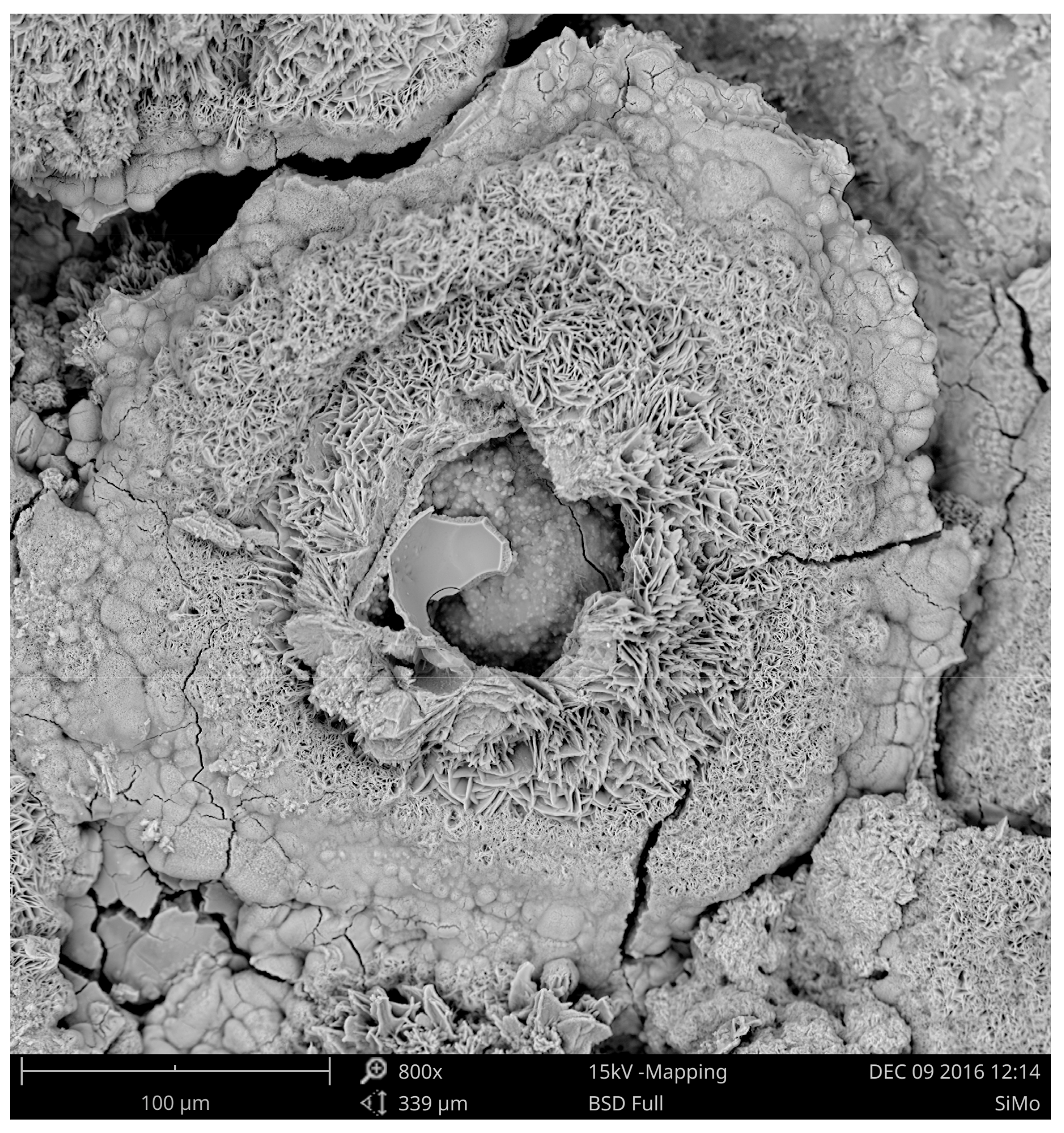
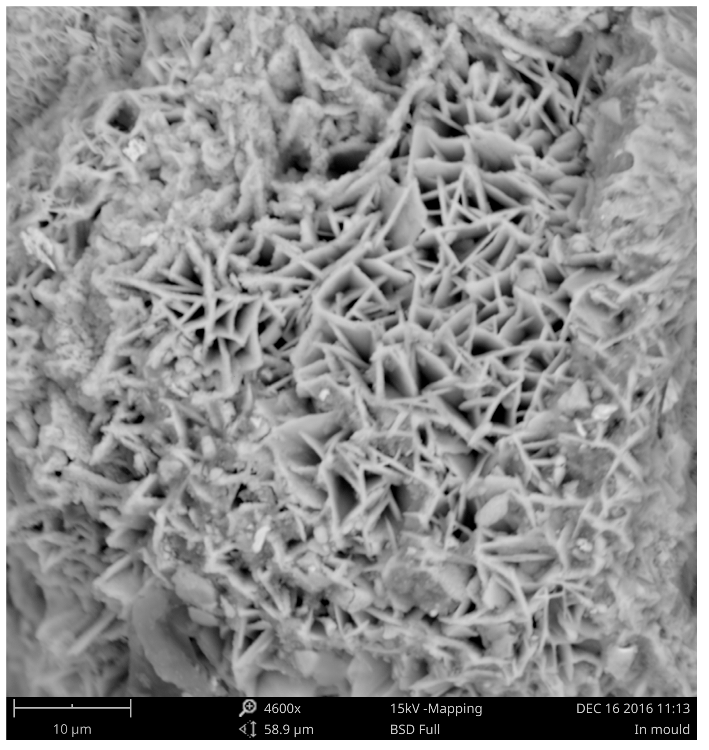
The next stage of research was to identify the compounds forming the surface layer of the sample. It should be noted that the tested samples did not undergo any corrosion-accelerating treatment. The samples were stored under constant humidity and ambient temperature (ca. 20 °C). As a result of the external environment they were covered with corrosion products, which is shown in Figure 7 and Figure 8. Samples with a similar chemical composition that were nodularized using the sandwich method showed no corrosion, although the conditions and storage times were the same.
As shown in Figure 7 and Figure 8, the surface of the casting is covered with corrosion products—mainly iron oxides and sulfides. The results of chemical composition analysis of corrosion products based on EDS are presented in Figure 9.
As seen in Figure 9, peaks of sulfur are also visible apart from typical corrosion products. Therefore, it should be assumed that the products of reaction of sulfur with the nodulizer flowed to the surface of the casting and created favorable conditions for the intensification of corrosive phenomena. The resulting corrosion product layer is poorly adhering and there is no passivation phenomenon in this case, as was mentioned in [7]. Figure 7 shows some cracks in the oxide layer that could have resulted in the intensification of corrosive phenomena. These types of corrosion products on the surface of the casting very easily absorb humidity from the environment, and other factors favoring corrosion processes may also play a role here. Pitting corrosion might also occur in this case, which constitutes a danger to the proper and safe operation of machinery and equipment. A view of the pitting defect [8], which is the result of accelerated tests on ductile iron, is presented below in Figure 10.
4. Conclusions
The experimental studies conducted here provide information on the quality of castings produced using the in-mold method of nodularization. As a result of the quality analysis, visible signs of corrosion on the surface of the experimental cast were observed. It should be noted that corrosive phenomena appeared in the upper part of the casting. The first signs of corrosion can be observed after about one month of storage of the casting under a constant temperature and air humidity, counting from the time of its production. If a casting produced based on the nodularization process in-mold shows a tendency to corrode under storage conditions in a locked room, where the effect of corrosive factors is limited, it should be assumed that such castings exposed to varying temperatures, periodic humidity changes, etc. will undergo corrosion processes in a more violent manner. The reason for this state are the MgS and CeS compounds that formed as a result of the reaction of sulfur contained in the cast iron with the nodularizing mixture. These compounds cannot be eliminated from the metal bath in this production process. Their low density causes them to flow to the surface layer of the casting, thus reducing its quality. It thus seems obvious that sulfur in cast iron should be eliminated or reduced to a minimum during the nodularization process in mold; however, authors [9,10,11,12,13,14] noted that there is a certain minimum amount of sulfur in cast iron that is required to produce cast iron of an adequate quality due to the correct morphology of graphite precipitates. The authors [1] showed the production process of cast iron castings with vermicular graphite precipitates, where sulfur compounds were deliberately added into the liquid alloy. It is important to note that the quality of castings produced based on the in-mold method of nodularization might be decreased by corrosion phenomena (particularly in the surface and near-surface layer of the casting). Another issue that contributes to the lower quality of the castings is the presence of iron, silicon, and oxygen compounds (fayalite-Fe2SiO4) and of compounds of magnesium, silicon, and oxygen (forsterite-Mg2SiO4), as have been presented and described in this work. Both types of inclusions have lower density than cast iron, so they flow upwards (similarly to sulfur compounds). However, castings produced based on the in-mold method are also small-dimension castings, i.e., up to 3 kg, where the solidification and crystallization rate is so large that the inclusions described above are bounded in the entire volume of the casting. It should be noted that these types of inclusions form a discontinuity in the metal matrix and decrease tensile strength and plasticity. This becomes important for cast parts of machines or devices with special requirements, where operational safety is a priority. Therefore, the results published in this paper draw attention to some of the disadvantages and problems connected with the production process of castings from ductile iron. It is important to consider whether the in-mold process is always a well-chosen manufacturing process for the production of particularly sensitive parts of machines and equipment.
Author Contributions
Marcin Stawarz: conceived and designed the experiments, performed the experiments, analyzed the data, wrote the paper. Krzysztof Janerka: conceived and designed the experiments, analyzed the data, wrote the paper. Malwina Dojka: contributed materials/analysis tools, analyzed the data, wrote the paper.
Conflicts of Interest
The authors declare no conflict of interest.
References
- Riposan, I.; Chisamera, M.; Kelley, R.; Barstow, M.; Naro, R.L. Magnesium-sulfur relationships in ductile and compacted graphite cast irons as influenced by late sulfur additions. Am. Foundry Soc. Trans. 2003, 869–884. [Google Scholar]
- Irons, G.A.; Guthrie, R.I.L. Kinetic aspects of magnesium desulfurization of blast furnace iron. Ironmark. Steelmark. 1981, 8, 114–121. [Google Scholar]
- Lide, D.R. Handbook of Chemistry and Physics, 84th ed.; CRC Press LLC: New York, NY, USA, 2004; p. 746. [Google Scholar]
- Campbell, J. A Hypothesis for cast iron microstructures. Met. Mater. Trans. Part B 2009, 40, 786–801. [Google Scholar] [CrossRef]
- Janerka, K.; Pawlyta, M.; Jezierski, J.; Szajnar, J.; Bartocha, D. Carburiser properties transfer into the structure of melted cast iron. J. Mater. Process. Technol. 2014, 214, 794–801. [Google Scholar] [CrossRef]
- Stawarz, M. SiMo ductile iron crystallization process. Arch. Foundry Eng. 2017, 1, 147–152. [Google Scholar] [CrossRef]
- Kajzer, A.; Kajzer, W.; Gołombek, K.; Knol, M.; Dzielicki, J.; Walke, W. Corrosion resistance, eis and wettability of the implants made of 316 LVM steel used in chest deformation treatment. Arch. Met. Mater. 2016, 61, 767–770. [Google Scholar] [CrossRef]
- Stawarz, M.; Kajzer, W.; Kajzer, A.; Dojka, M. Physicochemical properties of silicon cast iron. Arch. Foundry Eng. 2008, 17, 101–106. [Google Scholar] [CrossRef]
- Kopyciński, D.; Guzik, E. Effective inoculation of low-sulphur cast iron. Arch. Foundry Eng. 2008, 4, 77–80. [Google Scholar]
- Gumienny, G.; Kacprzyk, B.; Gawroński, J. Effect of copper on the crystallization process, microstructure and selected properties of CGI. Arch. Foundry Eng. 2017, 1, 51–56. [Google Scholar] [CrossRef]
- Trepczyńska-Łent, M. Solid-liquid interface morphology of white carbide eutectic during directional solidification. Arch. Met. Mater. 2017, 62, 365–368. [Google Scholar] [CrossRef]
- Zuk, M.; Gorka, J.; Dojka, R.; Czuprynski, A. Repair welding of cast iron coated electrodes. In IOP Conference Series-Materials Science and Engineering, Proceedings of the 5th International Conference on Modern Technologies in Industrial Engineering (ModTech), Sibiu, Romania, June 14–17 2017; Kifor, C., Naito, M., Carausu, C., Topala, P., Wrobel, A., Oanta, E., Schnakovszky, C., Paunoiu, V., Spanu, S., Nedelcu, D., Eds.; IOP Publishing Ltd.: Bristol, UK, 2017. [Google Scholar]
- Pacyniak, T.; Kaczorowski, R. Ductile cast iron obtaining by inmold method with use of lost foam process. Arch. Foundry Eng. 2010, 1, 101–104. [Google Scholar]
- Wilk-Kolodziejczyk, D.; Regulski, K.; Gumienny, G. Comparative analysis of the properties of the nodular cast iron with carbides and the austempered ductile iron with use of the machine learning and the support vector machine. Int. J. Adv. Manf. Techol. 2016, 87, 1077–1093. [Google Scholar] [CrossRef]
Figure 1.
Scheme of the gating system for the in-mold process.

Figure 2.
Scheme of location where the metallographic samples was collected.

Figure 3.
Sectional view of the surface layer of the casting with the fayalite precipitate marked with the number 2.
Figure 3.
Sectional view of the surface layer of the casting with the fayalite precipitate marked with the number 2.
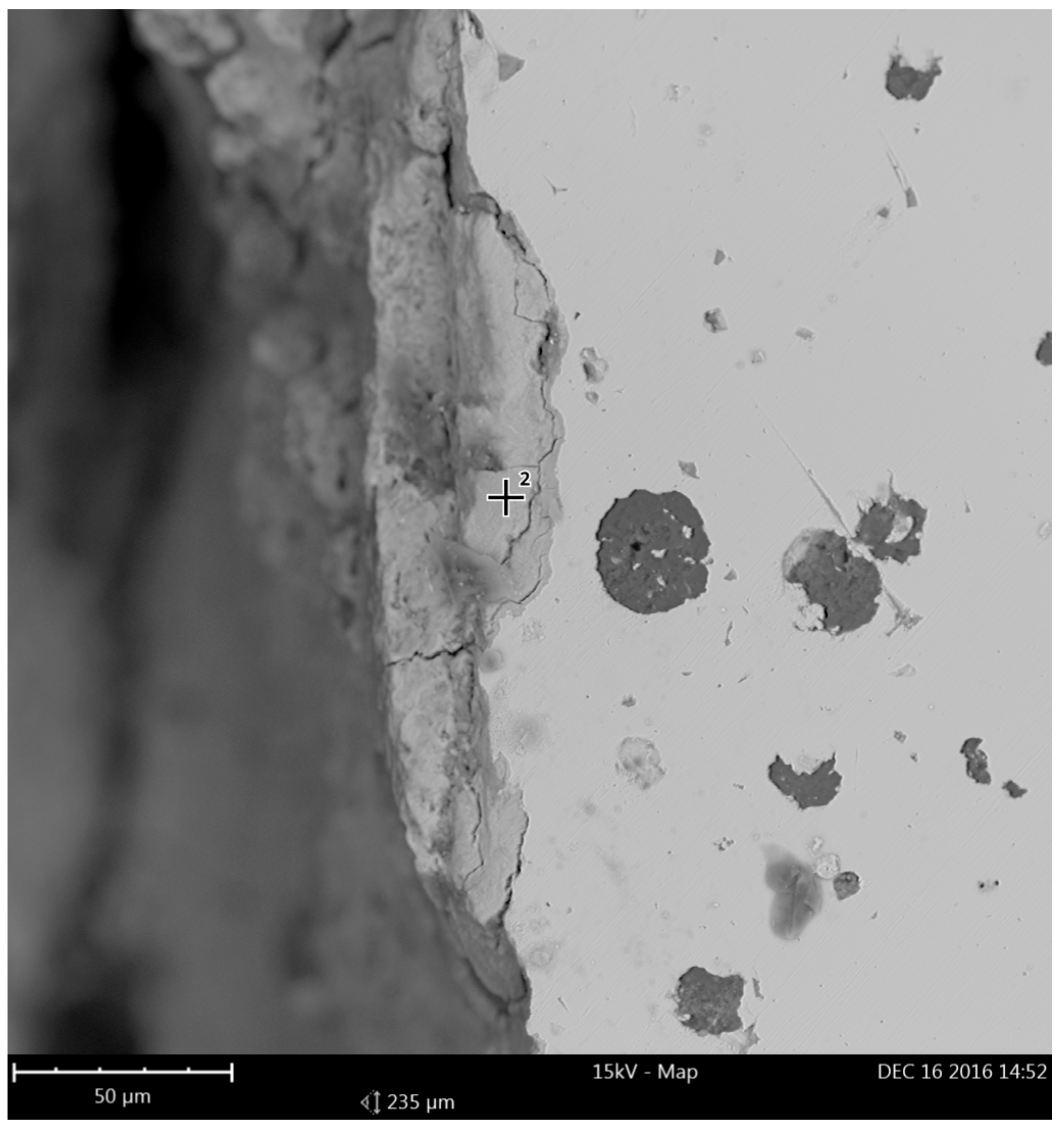
Figure 4.
EDS point analysis of the area marked in Figure 2 (fayalite).
Figure 4.
EDS point analysis of the area marked in Figure 2 (fayalite).
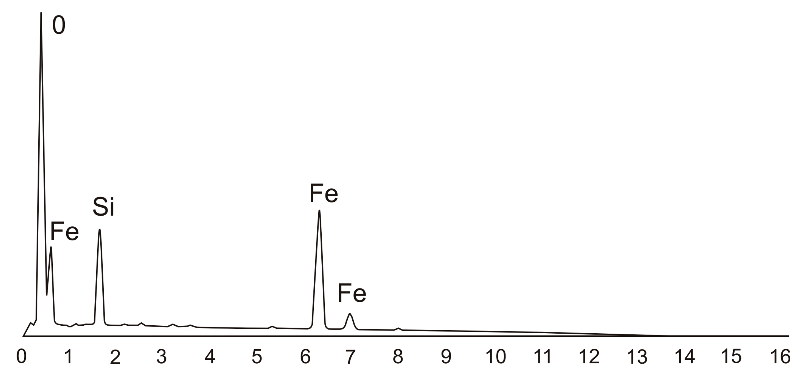
Figure 5.
Forsterite inclusion (Mg2SiO4).
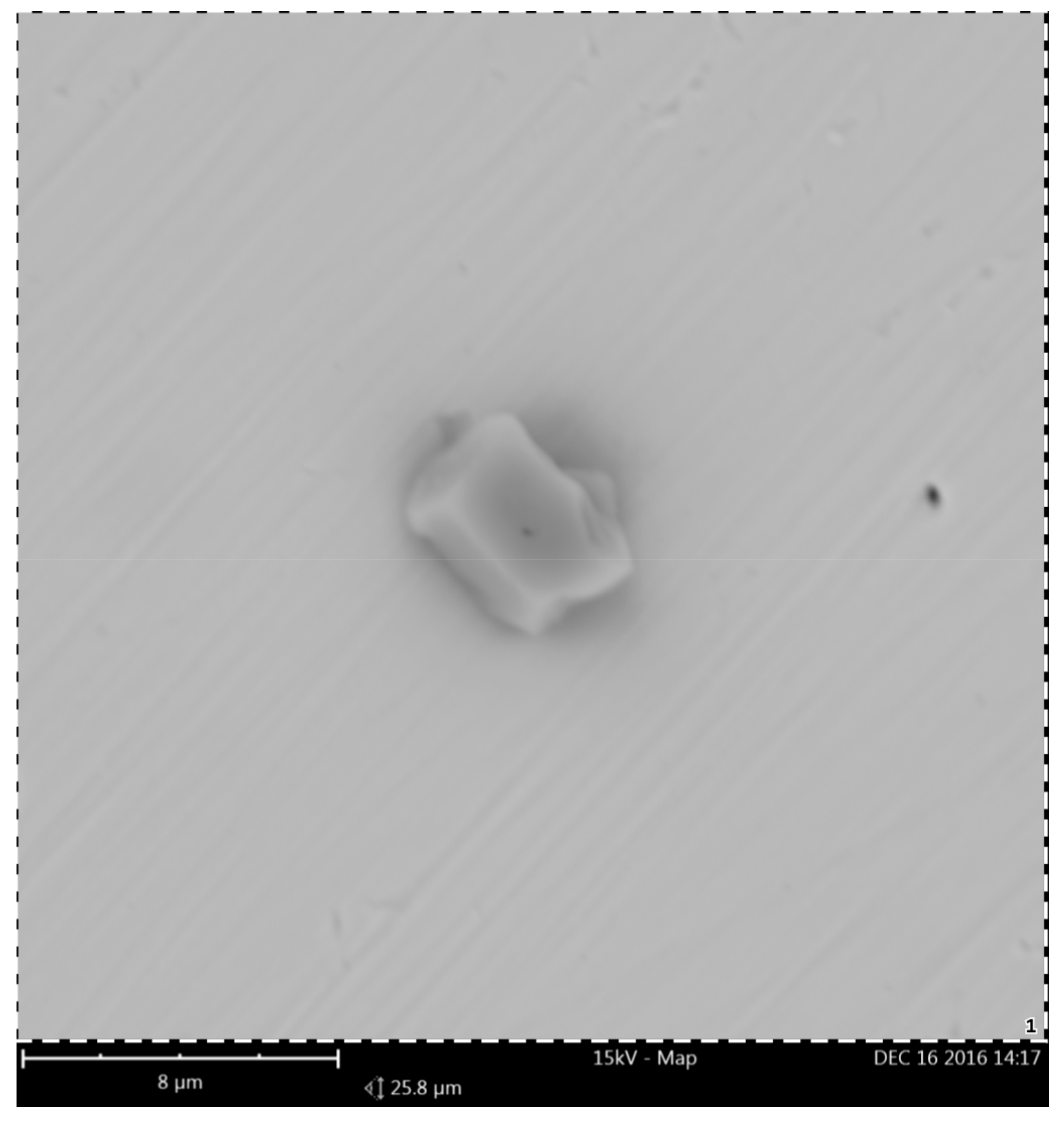
Figure 6.
EDS point analysis of inclusion present in Figure 4 (forsterite).
Figure 6.
EDS point analysis of inclusion present in Figure 4 (forsterite).
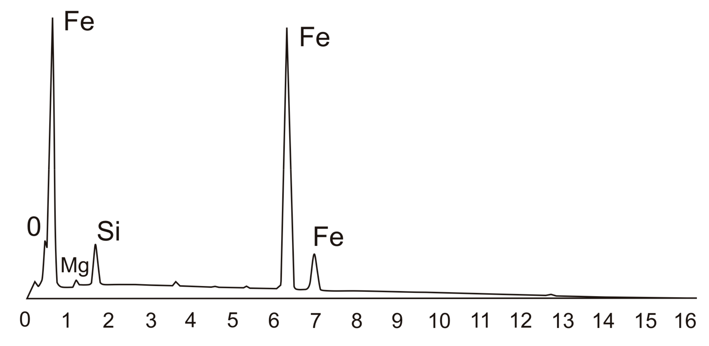
Figure 7.
Corrosion products on the surface of the ductile iron casting done using the in-mold method.
Figure 7.
Corrosion products on the surface of the ductile iron casting done using the in-mold method.
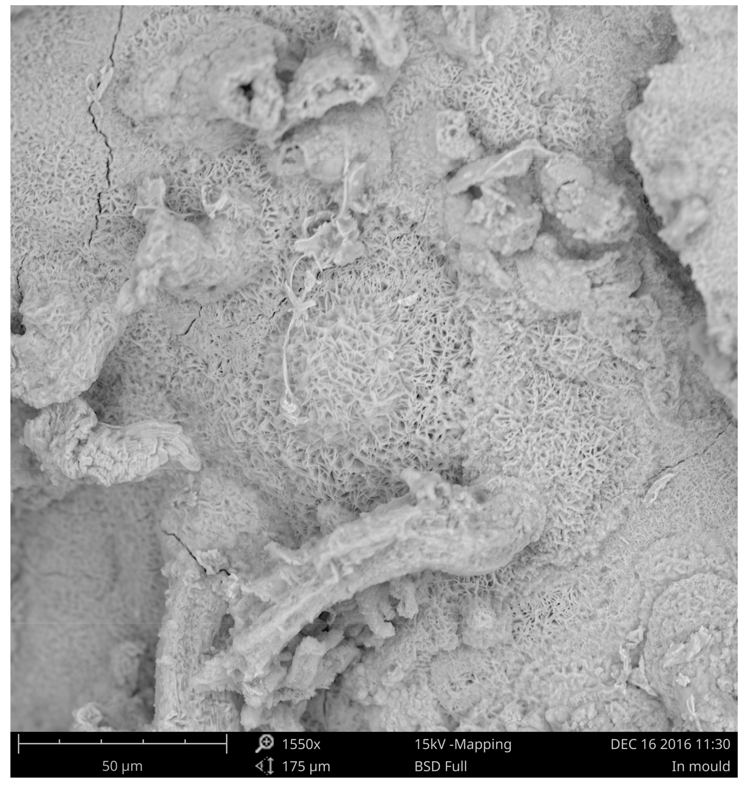
Figure 8.
Layer of poorly adhering corrosion products on the surface of the ductile iron casting done using the in-mold method.
Figure 8.
Layer of poorly adhering corrosion products on the surface of the ductile iron casting done using the in-mold method.

Figure 9.
Results of the EDS analysis for the corroded ductile iron casting made with the in-mold method.
Figure 9.
Results of the EDS analysis for the corroded ductile iron casting made with the in-mold method.
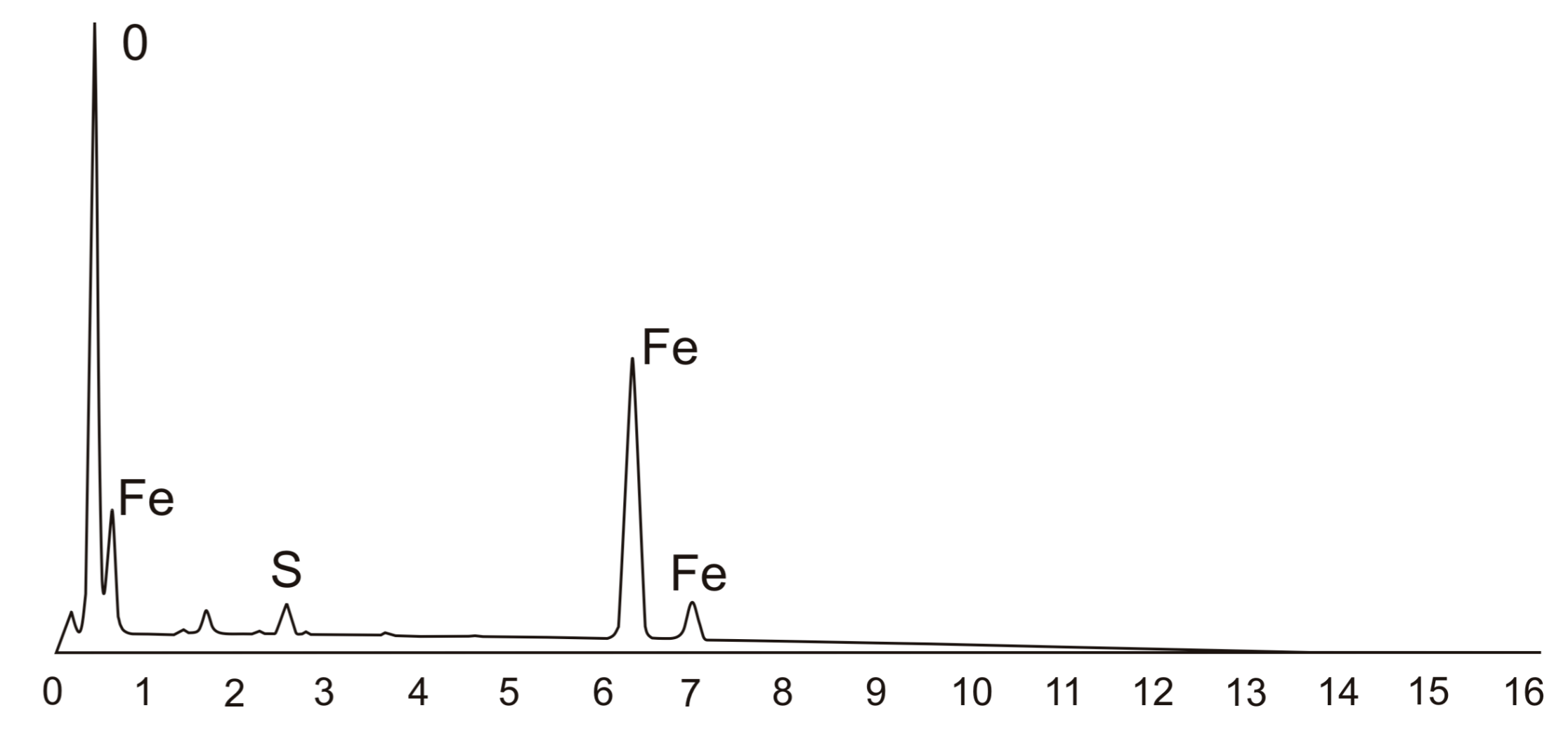
Figure 10.
Area of ductile iron casting covered with pitting corrosion.

Table 1.
Chemical composition of the examined ductile iron.
| Chemical Composition/wt.% | |||||||
|---|---|---|---|---|---|---|---|
| C | Mn | Si | P | Mo | S | Mg | |
| 1 * | 3.65 | 0.089 | 2.87 | 0.03 | 0.001 | 0.015 | - |
| 2 ** | 3.64 | 0.087 | 2.94 | 0.03 | 0.001 | 0.012 | 0.041 |
* Chemical composition of a sample taken from the furnace, ** chemical composition of the examined casting.
© 2017 by the authors. Licensee MDPI, Basel, Switzerland. This article is an open access article distributed under the terms and conditions of the Creative Commons Attribution (CC BY) license (http://creativecommons.org/licenses/by/4.0/).
Share and Cite
MDPI and ACS Style
Stawarz, M.; Janerka, K.; Dojka, M. Selected Phenomena of the In-Mold Nodularization Process of Cast Iron That Influence the Quality of Cast Machine Parts. Processes 2017, 5, 68. https://doi.org/10.3390/pr5040068
AMA Style
Stawarz M, Janerka K, Dojka M. Selected Phenomena of the In-Mold Nodularization Process of Cast Iron That Influence the Quality of Cast Machine Parts. Processes. 2017; 5(4):68. https://doi.org/10.3390/pr5040068
Chicago/Turabian StyleStawarz, Marcin, Krzysztof Janerka, and Malwina Dojka. 2017. "Selected Phenomena of the In-Mold Nodularization Process of Cast Iron That Influence the Quality of Cast Machine Parts" Processes 5, no. 4: 68. https://doi.org/10.3390/pr5040068
Note that from the first issue of 2016, this journal uses article numbers instead of page numbers. See further details here.