Recovery of Filtered Graphene Oxide Residue Using Elastic Gel Packed in a Column by Cross Flow
by
Yuji Takaoka
, 
Manoka Miyoshi
,
Koichi Sakaguchi
,
Shintaro Morisada
,
Keisuke Ohto
and
Hidetaka Kawakita
* Department of Applied Chemistry, Saga University, Saga 840-8502, Japan
*
Author to whom correspondence should be addressed.
Processes 2018, 6(5), 43; https://doi.org/10.3390/pr6050043
Submission received: 28 March 2018
/
Revised: 20 April 2018
/
Accepted: 23 April 2018
/
Published: 25 April 2018
(This article belongs to the Special Issue Membrane Materials, Performance and Processes)
Abstract
:To recover the filtered residues on a gel layer in a column, the method using the elasticity of the gel layer and flowing water in a cross-flow manner is proposed. Polymerized spherical gel (40 μm) was packed in a column to a set height of 0.7 cm. The suspensions of graphene oxide at various sizes and shapes were injected on the top of the gel layer and then water was flowed at a flow rate of 1000 mL·h−1 until 0.10 MPa. By releasing the applied pressure, the elastic gel layer rose up, and the filtered graphene oxide also rose above the layer. This rise of the gel layer is due to the difference of pressure between the gel layer, including the filtered graphene oxide, and the open bottom of the column, using the flow of water. The cross flow of water through the column carried away the larger-sized filtered graphene oxide floating above the gel layer. The elasticity of the gel layer and cross flow through the column has the potential to recover the filtered particles.
1. Introduction
Filtration techniques have been used for particle and polymer separation based on the difference of shapes and sizes. By filtration, filtered particles remain in the pores of the membrane and the filter as a residue. To recover the filtrated residues, the methods using the shear stress by cross flow [1,2] and using the dynamic motion of magnetite particles with the application of a magnetic field on the membrane and the support [3,4] have been proposed. The sophisticated methods to recover filtered particles led also to the anti-fouling of the pore of the membrane and the filter.
Gel has a three-dimensional matrix and elastic characteristics. When water is permeated from the top of the spherical-gel packed column, the packed gel at the bottom of the column is subjected to a greater force, which leads to a deformation of the packed gel from a spherical to an ellipsoidal- and collapsed-polyhedron-like morphology [5,6]. So far, this deformation of the gel layer was used for particle separation [7]. By releasing the applied pressure, the elastic force from the deformed gel rises and, as a result, the packed gel layer rises up because the pressure difference between the gel layer and the opened bottom of the column generates the fluid flow from the bottom of the column. The height change of the gel layer during rising would be dependent on the rigidity, the diameter, and the concentration of the packed gels.
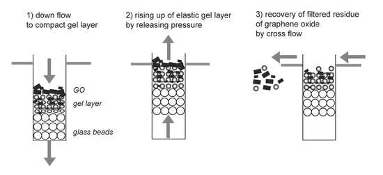
Using the elasticity of the spherical gel packed in the column, the following method to recover filtered residue is proposed (Figure 1): (1) the solution, including filtered particles, is injected on the top of the gel layer and water is flowed through the gel layer for the filtration; (2) the gel layer rises up by releasing the applied pressure; and (3) the filtered residues floating above the gel layer are recovered by the cross flow. During filtration the smaller particles injected penetrate into the deformed gel layer, showing the possibility of particle separation.
In this study, the filtration target used is graphene oxide (GO). GO has various sizes and shapes produced by chemical synthesis. Due to the high electron transfer and heat transfer of the material, GO has been separated using centrifugation and chromatographic techniques [8,9] in the range of a few hundred nm to a few µm. Additionally, chemical modification induces the assembly aggregates of graphene oxides via electrostatic and van der Waals interaction. The uniform size of GO has been required for subsequent applications in electronic devices. Filtration has the potential separation technique to separate the GO. So far, the techniques by porous membranes have been proposed for the separation of particles. The performance of the membrane separation was changeable to introduce colloidal particles and a polymer brush to the membrane, and to form the skin layer on the membrane surface. However, the filtered particles remained in the membrane pores to reduce the membrane performance of separation and permeation flux. In the case of GO, there are still problems in that no recovery methods of filtered larger-sized GO exist. Concretely, with the aim of the proposed recovery process of filtered GO, as shown in Figure 1, the following items are studied: (1) measurement of the rise-up height of the elastic gel layer by releasing the applied pressure; and (2) the recovery of filtered GO by the gel layer using cross flow through the column. Not only with respect to the recovery of the filtered GO, but also to the separation of various sizes of GO in the gel layer, the elastic gel layer has potential, leading to a synergistic separation and recovery process.
2. Experimental
2.1. Materials
N,N-Dimethylacrylamide, azobis-iso-butyronitrile, and carboxymethylcellulose sodium were purchased from Wako Pure Chemical Industries Ltd. (Osaka, Japan) N,N′-methylene bisacrylamide and sodium phosphate dodecahydrate were obtained from Tokyo Chemical Industry Co., Ltd. (Tokyo, Japan). and Sigma-Aldrich Co. (St Louis, MO, USA), respectively. Graphite (size 5 µm, thickness 6 nm) was obtained from XG Sciences, Inc. (East Lansing, MI, USA). Glass beads (100 µm, AS-ONE BZ-01) were obtained from As-One Corporation (Osaka, Japan). The column (I.D.: 0.50 cm, height 10 cm) was purchased from Bio-Rad Laboratories, Inc. (Hercules, CA, USA). Other chemicals were of analytical grade or higher.
2.2. Preparation of the Spherical Gel
The preparation condition of the spherical gel is summarized in Table 1. The polymerization condition was based on the reference of Hirayama et al. [10]. The water phase including sodium sulfate, calcium carbonate, carboxymethylcellulose sodium, and sodium phosphate dodecahydrate was mixed at 343 K at a rotation speed of 500 rpm. The monomer phase was prepared using N,N-dimethylacrylamide, N,N′-methylene bisacrylamide, and azobis-iso-butyronitrile. The monomer phase was dropped into the water phase at a rotation of 500 rpm at 343 K for four hours. After the polymerization, the obtained product was washed with water twice, 1 M HCl solution, and water two times. Water on the gel was wiped off and the concentration of the gel suspension was set at 10 (w/w%) with water. The gel sample was analyzed by optical microscopy (VH-S5, Keyence, (Keyence Corporation, Osaka, Japan)) to determine the size distribution from more than 200 particles.
2.3. Preparation of Graphene Oxide
Two (2.0) grams of graphite, 2.4 g of KNO3 and 248 g of HNO3 were mixed in an ice bath. With stirring, 9.0 g of KMnO4 was added in the bath of ice water for 20 min and the reaction was performed for 72 h. Five milliliters of H2O2 (30%) was added to the reactor with stirring for one hour and then 200 mL of 10% HCl was added with stirring for 30 min. Centrifugation (3500 rpm, 30 min, room temperature; AS185, As One, Osaka, Japan) was performed to recover the product of graphene oxide three times. Solid graphene oxide was separated using a dialysis tube (cutoff: 12–14 kDa, Nihon Medical Sciences, Inc., Osaka, Japan). The precipitant in the dialysis tube was recovered by centrifugation (15,000 rpm, 60 min, room temperature). The obtained precipitant was lyophilized using a lyophilizer (FD-1000, EYELA, Tokyo, Japan).
2.4. Filtration of Graphene Oxide and the Rising of the Gel Layer
Glass beads (0.30 g) were packed in the column to set the height at 1.0 cm. The gel suspension (10 (w/w%) was firstly dispersed by an ultrasonicator (AS ONE, USK-3R, Osaka, Japan). The gel suspension (1.5 mL) was added to the column and the gel sphere was packed via gravity for 12 h to set the height of the gel layer at 0.7 cm. The volume of the gel layer was calculated to be 0.14 mL. GO was dispersed in pure water. GO suspensions (1.0 g·L−1) at various volumes (0.02–0.3 mL) were injected at the top of the gel layer. Water was permeated through the gel layer at a flow rate of 1000 mL·h−1 up to 0.1 MPa. Then, by opening the three-way cock, the applied pressure was released and the rise of the gel layer was observed by camera. The height of the rise of the elastic gel layer was measured.
2.5. Recovery of Filtered Graphene Oxide on the Rising Gel by Cross Flow
A hole (diameter 0.3 cm) was drilled in the column at the height of 4.0 cm from the bottom of the column to make a path for the flowing water in a cross-flow manner. GO suspension (1.0 g·L−1, 0.2 mL) was injected at the top of the gel layer as mentioned in the above section. From the top of the column, water was permeated at 1000 mL·h−1 up to 0.10 MPa, and then the pressure was released to raise the gel layer. Subsequently, cross flows at flow rates of 170 and 320 mL·h−1 were individually performed to recover the filtered residue of GO on the gel layer. Recovered GO by cross flow was observed by optical microscopy and dynamic light scattering (ELSZ-1, Otsuka Electronics, Osaka, Japan).
3. Results and Discussion
3.1. Dependence of the Height of the Rise of the Gel Layer on the Injected Volume of the Graphite Oxide Suspension
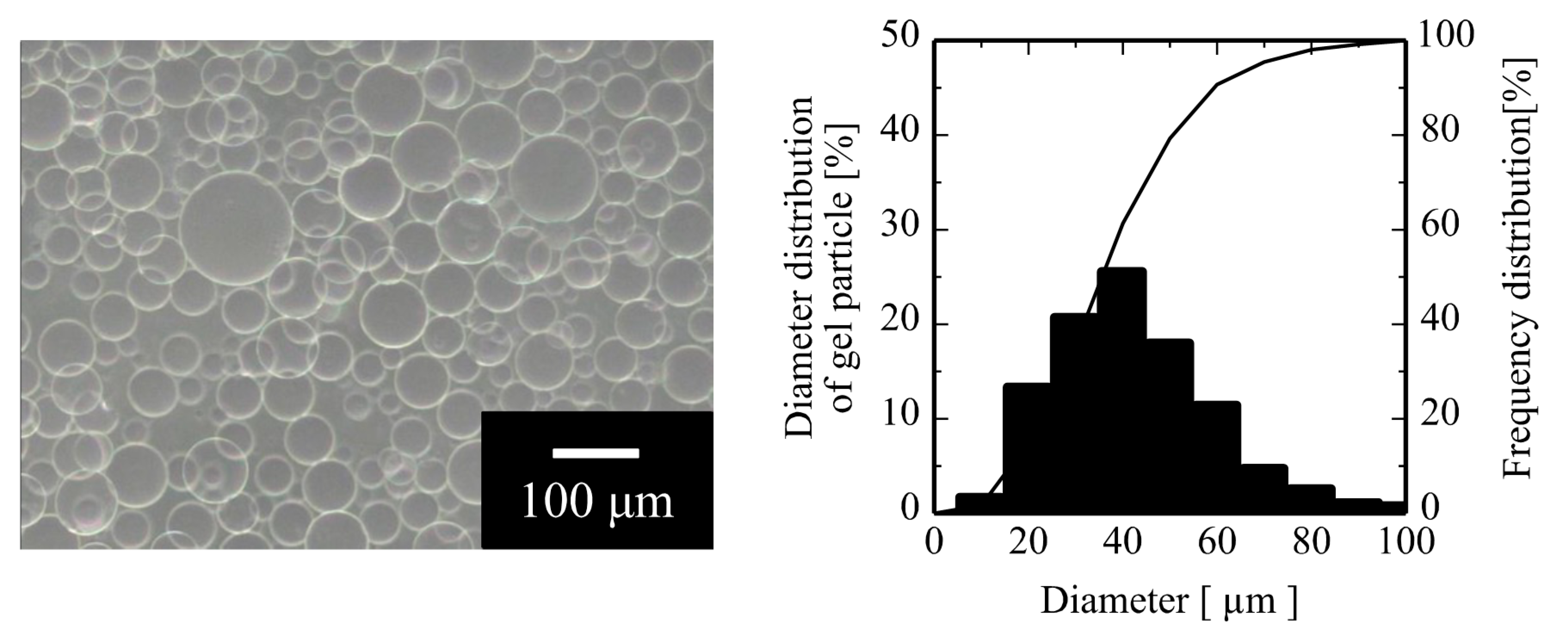
The monomer phase was dispersed in a highly-concentrated salt solution to polymerize the spherical gel, as per the reference by Hirayama et al. [10]. Monomer of dimethylacrylamide is known to form the phase separation at more than 20 (w/w%) sodium sulfate solution. Moreover, carboxymethylcellulose adsorbs at the interface to stabilize the droplet of the monomer phase as a sphere. The morphology and size distribution of the obtained spherical gel after polymerization are shown in Figure 2. The mean size of the obtained gel was about 40 μm. The size distribution of the gels influences the separation of the particles because the gaps among the gels function as pores for filtration. To optimize the separation performance of the particle by the gel layer, polymerization conditions, heterogeneity of the obtained gel, and the packed structure of the gel in column should be considered. In the polymerization reactor, the monomer was polymerized in the presence of shear stress by stirring. Unstable shear stress to the monomer phase forms the distributed size of the spherical gel layer. If the ratio of the moles of the monomer and the crosslinker was changed, the elasticity of the spherical gel would be controllable due to the different distance between the main polymer chain and the crosslinker, as well as the spatial inhomogeneous network in the gel. Gundogan et al. investigated the effect of the initial molarity of the monomer, N-N′-dimethylacrylamide, against that of the crosslinker, N-N′-methylenebisacrylamide, to determine the swelling performance along with the elasticity. They concluded that swelling behavior was classified into three categories according to the polymer concentration [11]. At a higher polymer concentration, the modulus of the elasticity dramatically increased due to the entanglement of the polymers.
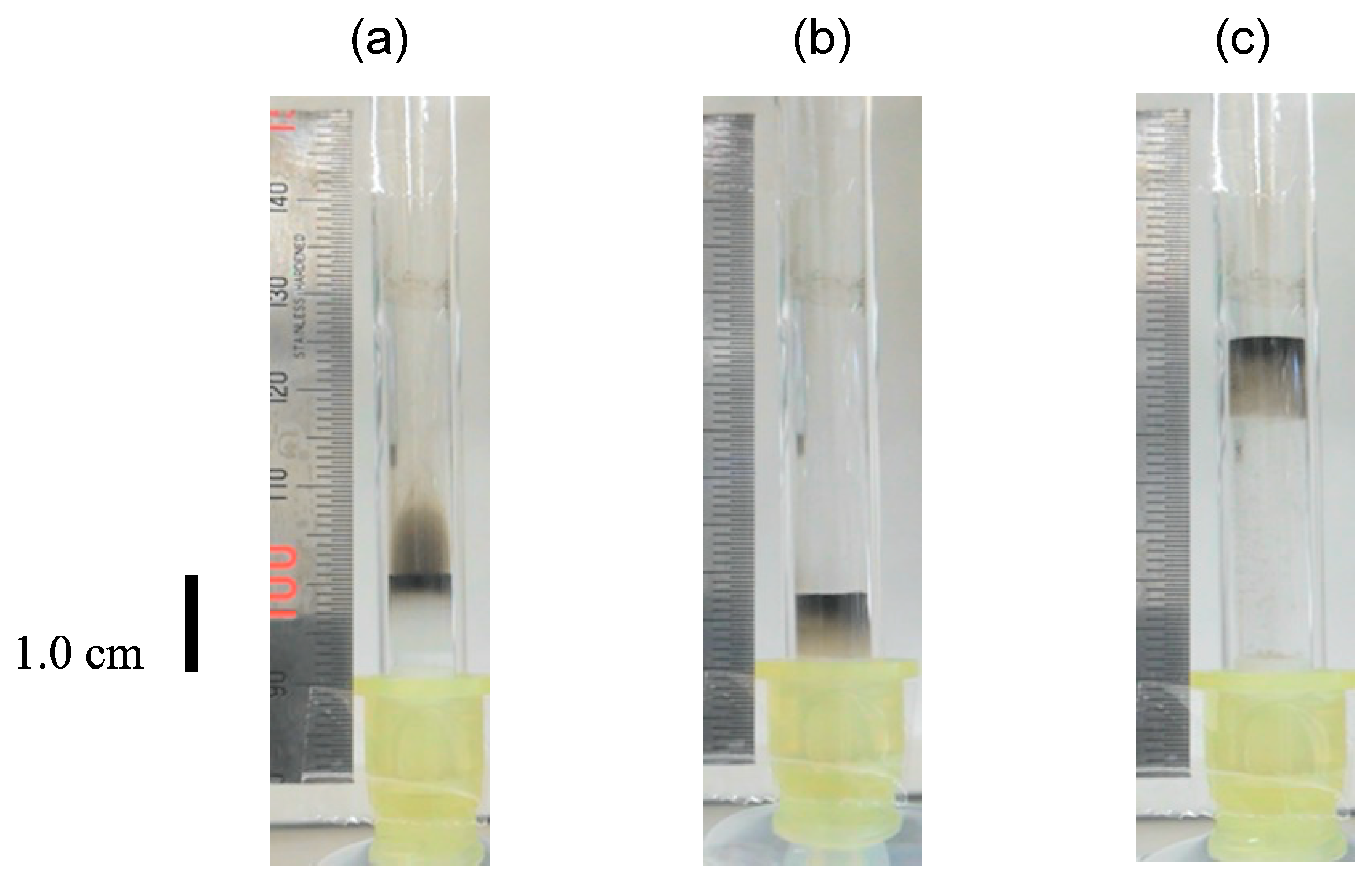
Glass beads and the obtained gel suspensions were packed in the column and then the GO suspension (1.0 g·L−1) was injected on the top of the gel layer. Water was permeated through the gel layer and the applied pressure was released by opening the three-way cock, raising the gel layer, as shown in Figure 3. In the images of Figure 3, (a) injected GO suspension on the top of the gel layer diffused above the gel layer, and (b) GO at the smaller size moved to the inner part of the deformed gel layer via convection. However, GO at the larger size hardly moved into the gel layer and remained on the surface of the gel layer. The height of the gel layer reduced in flowing water due to the deformation of spherical gel particles, as mentioned in [7]. When the system is used for separation, gaps in the packed gel function as membrane pores. Distances of the gaps between the packed gel particles, especially at the bottom of the gel layer, depend on the fluid flow rate, which changes the separation performance of the particles. In Figure 3c, by releasing the applied pressure, the elastic gel layer returned to the original state to demonstrate the rise of the gel layer. By releasing the pressure, since water flowed through the gel layer from the bottom, the filtered and captured GO in the gel layer received the pressure of flowing water, resulting in the rise of the gel layer.
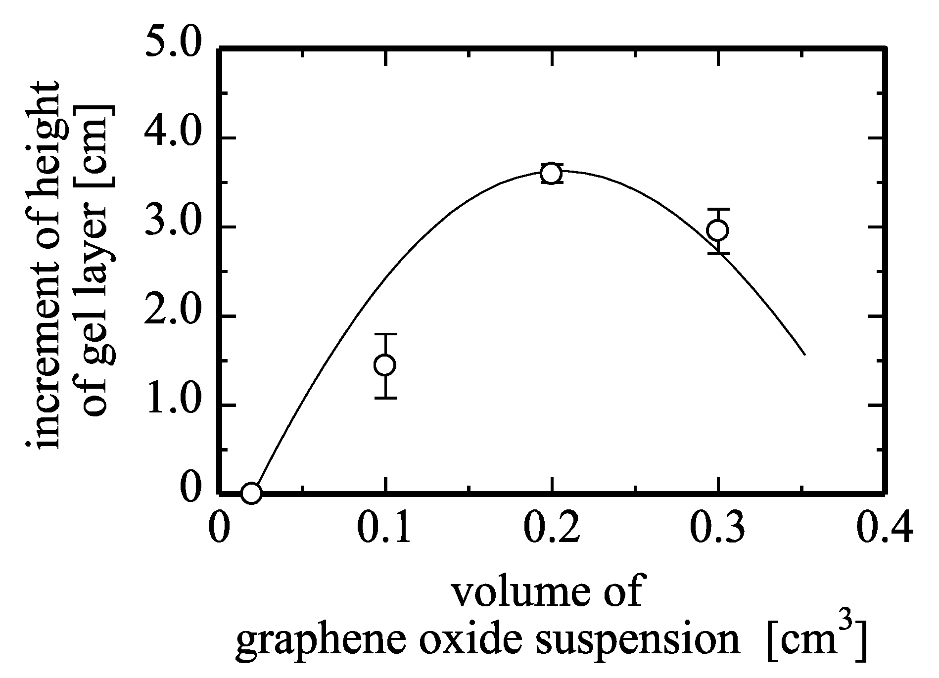
The height of the rise of the gel layer at various volumes of GO suspension injected on the gel layer by flowing water and releasing the applied pressure is shown in Figure 4. With an increase in the injected volume of the GO suspension to 0.2 mL, the height of rise of the gel layer increased. At the suspension volume of 0.2 mL the height was at its maximum. However, at 0.3 mL the rise height of the gel layer reduced.
Filtered GO occupied the space among the gels in the layer. In releasing the applied pressure, water flows from the bottom of the gel layer due to the pressure difference between the gel layer and the open bottom of the column. Since the filtered GO-gel layer received the resistance of flowing water from the bottom, the gel layer would rise up in the column. However, the volume increment of the injected GO suspension increased the filtered GO packed among the gel’s gaps, and the wall and the gel of the column reduced the height of the gel layer.
3.2. Recovery of the Filtered Graphene Oxide above the Gel Layer by Cross Flow
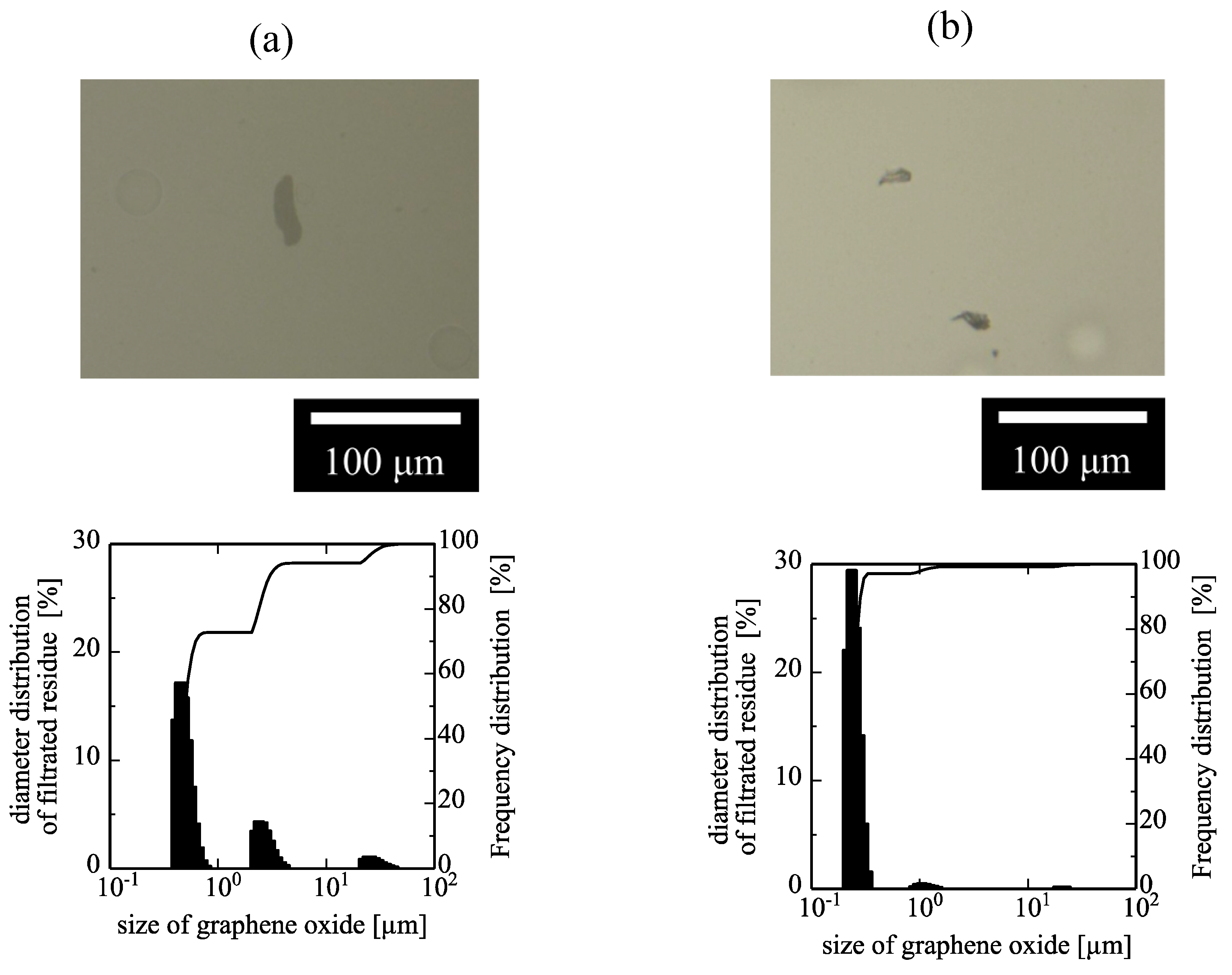
The path of the cross flow was drilled into the column. The hole was set at 4.0 cm from the bottom of the column, which was determined from the data of Figure 4. Using the elasticity of the gel layer, the filtered GO rose above the gel layer with release of the applied pressure. Cross flow might recover floating GO above the elastic gel layer after rising. The flow rate of the cross flow was set at 170 and 320 mL·h−1. The images of the recovered GO by the cross flow at 170 and 320 mL·h−1 are shown in Figure 5. This demonstrated that GO filtered by the elastic gel layer can be recovered by cross flow through the column. At the higher flow rate of cross flow, the smaller-sized GO was recovered. The measurement of dynamic light scattering, also in Figure 5, showed that GO recovered by cross flow at the higher flow rate includes the smaller-sized GO. At 170 mL·h−1 of cross flow, the size of the recovered GO was 15 µm, 3.0 µm and 700 nm, whereas the cross flow at 320 mL·h−1 changed the size of GO to be smaller, in which the size of GO at 300 nm was dominant since GO was filtered and captured at the inner part of the gel layer more by cross flow.
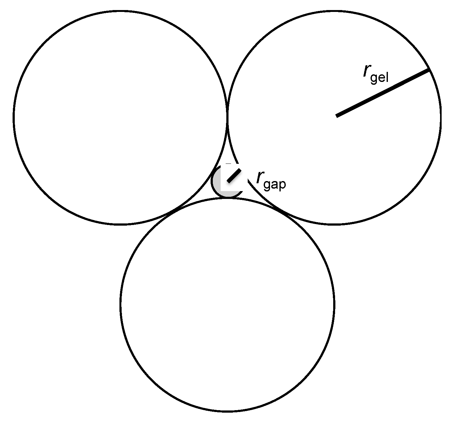
During the filtration of the GO suspension, GO was subjected to the force of shear stress. The stress was possibly calculated as follows: assuming that gel sphere was initially located as a closed-packed structure, the diameter of the gaps among the spherical gels, as shown in Figure 6, might be calculated as:
where rgap and rgel are the radius of the gaps and the spherical gel, respectively. rgap might be 3.0 µm, when rgel was 20 µm in this study. The superficial velocity at a flow rate of 1000 mL·h−1 through the column was calculated to be 1.4 × 10⁻² m·s−1. Therefore, the shear rate from the water flowing through the gaps among the gels was possibly determined to be 470 s−1 Vallés et al. determined the rheology of the GO suspension using a parallel-plate rheometer, indicating that the shear rate from 0.01 to 100 s−1 dispersed the aggregation of GO [12]. In this study, the high shear rate among the gels broke the aggregated GO during the filtration.
The size and rigidity of the spherical gel changed the elasticity of the gel layer in the column with the application of flowing fluid. The amount of the filtered particles by the gel layer was also changeable. This elasticity of the gel and cross flow of fluid is possibly applied not only for the elastic-gel-packed column, but also the elastic porous membrane. The foulant-including porous membrane with the elasticity has the ability to regenerate the permeation flux by switching the applied pressure on and off to remove the foulant from the surface of the membrane pores.
4. Conclusions
The recovery system of filtered graphene oxide using an elastic gel layer and cross flow through the column was proposed. Suspensions of graphene oxide (1.0 g·L−1) were injected on the top of the elastic gel layer (initial height 0.7 cm) and water was flowed through the gel layer. Due to the elasticity of the gel layer, the height of the gel layer in the column reduced. Graphene oxide at the larger size was filtered at the flow rate of 1000 mL·h−1 and remained at the top of the gel layer. By releasing the applied pressure of 0.1 MPa, the elastic gel layer rose up in column and the filtered graphene oxide floated above the gel layer. The height of the rise of the gel layer was dependent on the volume of the graphene oxide suspension. Cross flow was performed to recover the floating graphene oxide above the gel layer. At a crossflow rate of 170 mL·h−1, the dominant size of the recovered graphene oxide was 300 nm. This system has the potential application for the recovery of the separated colloidal particles and polymers on the elastic layer of the membrane and filter after the filtration.
Author Contributions
Y.T., M.M. and H.K. conceived and designed the experiments; M.M. performed the experiments; Y.T., M.M. and H.K. analyzed the data; K.S., S.M., K.O. and H.K. contributed reagents/materials/analysis tools; Y.T. and H.K. wrote the paper.
Acknowledgments
We thank Edanz Group (www.edanzediting.com/ac) for editing a draft of this manuscript. The dynamic light scattering analysis was made at the Analytical Research Center for Experimental Sciences, Saga University.
Conflicts of Interest
The authors declare no conflict of interest.
References
- Satyanarayana Chilukuri, V.V.; Marshall, A.D.; Munro, P.A.; Singh, H. Effect of sodium dodecyl sulphate and cross-flow velocity on membrane fouling during cross-flow microfiltration of lactoferrin solutions. Chem. Eng. Proc. 2001, 40, 321–328. [Google Scholar] [CrossRef]
- Makabe, R.; Akamatsu, K.; Nakao, S. Mitigation of particle deposition onto membrane surface in cross-flow microfiltration under high flow rate. Sep. Purif. Technol. 2016, 160, 98–105. [Google Scholar] [CrossRef]
- Himstedt, H.H.; Yang, Q.; Dasi, L.P.; Qian, X.; Wickramasinghe, S.R.; Ulbricht, M. Magnetically activated micromixers for separation membranes. Langmuir 2011, 27, 5574–5581. [Google Scholar] [CrossRef] [PubMed]
- Tanaka, T.; Uno, Y.; Morisada, S.; Ohto, K.; Kawakita, H. Filtration and recovery of starch granules using assembled magnetite filter. Chem. Eng. Proc. 2016, 110, 128–133. [Google Scholar] [CrossRef]
- Lu, W.-M.; Tung, K.-L.; Hung, S.-M.; Shiau, J.-S.; Hwang, K.-J. Constant pressure filtration of mono-dispersed deformable particle slurry. Sep. Sci. Technol. 2001, 36, 2355–2383. [Google Scholar] [CrossRef]
- Ueyama, K.; Furusaki, S. A theoretical study on the effect of compaction on the effectiveness factor of gel particles containing immobilized enzymes. Chem. Eng. Commun. 1985, 36, 299–316. [Google Scholar] [CrossRef]
- Takaoka, Y.; Morisada, S.; Ohto, K.; Kawakita, H. Filtration of colloidal particles using compacted-gel media packed in a column. J. Chem. Eng. Jpn. 2017, 50, 815–820. [Google Scholar] [CrossRef]
- Bidram, E.; Sulistio, A.; Amini, A.; Fu, Q.; Qjao, G.G.; Stewart, A.; Dunstan, D.E. Fractionation of graphene oxide single nano-sheets in water-glycerol solutions using gradient centrifugation. Carbon 2016, 103, 363–371. [Google Scholar] [CrossRef]
- Smith, R.J.; King, P.J.; Wirtz, C.; Duesberg, G.S.; Coleman, J.N. Lateral size selection of surfactant-stabilized graphene flakes using size exclusion chromatography. Chem. Phys. Lett. 2012, 531, 169–172. [Google Scholar] [CrossRef]
- Hirayama, C.; Yamaguchi, K.; Matsumoto, K.; Motozato, Y. Preparation of poly(N,N-dimethylamide) gels having a void in the center of the bead by suspension copolymerization. Kobunshi Ronbunshu 1983, 40, 547–553. [Google Scholar] [CrossRef]
- Gundogan, N.; Okay, O.; Oppermann, W. Swelling, elasticity and spatial inhomogeneity of poly(N,N-dimethylacrylamide) hydrogels formed at various polymer concentrations. Macromol. Chem. Phys. 2004, 205, 814–823. [Google Scholar] [CrossRef]
- Vallés, C.; Young, R.J.; Lomax, D.J.; Kinloch, I.A. The rheological behavior of concentrated dispersions of graphene oxide. J. Mater. Sci. 2014, 49, 6311–6320. [Google Scholar] [CrossRef]
Figure 1.
Illustrated scheme of the recovery of filtered residues by using the elasticity of gels and cross flow.
Figure 1.
Illustrated scheme of the recovery of filtered residues by using the elasticity of gels and cross flow.
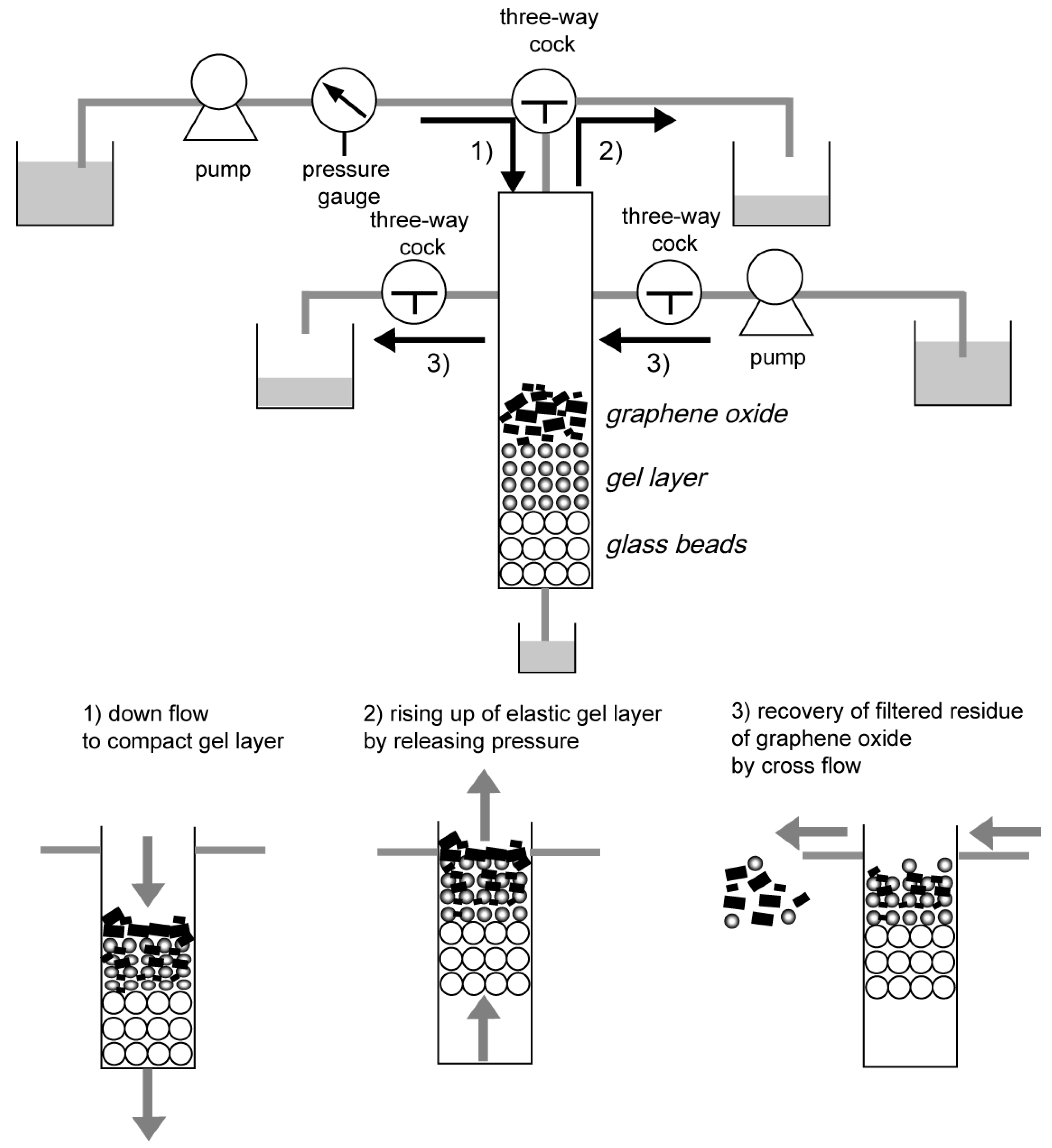
Figure 2.
Optical microscope image and size distribution of the obtained gel (150× magnification).

Figure 3.
Picture of the rising elastic gel layer in the column. (a) Before permeation; (b) during permeation; and (c) after releasing the applied pressure.
Figure 3.
Picture of the rising elastic gel layer in the column. (a) Before permeation; (b) during permeation; and (c) after releasing the applied pressure.

Figure 4.
Height of gel layer vs. volume of graphene oxide suspension. Initial height of gels: 0.7 cm, conc. of graphene oxide: 1.0 g·L−1; the flow rate of water: 1000 mL·h−1.
Figure 4.
Height of gel layer vs. volume of graphene oxide suspension. Initial height of gels: 0.7 cm, conc. of graphene oxide: 1.0 g·L−1; the flow rate of water: 1000 mL·h−1.

Figure 5.
Optical microscope images and size distribution of recovered graphene oxide measured by dynamic light scattering by the cross flow at flow rates of (a) 170 mL/h and (b) 320 mL/h.
Figure 5.
Optical microscope images and size distribution of recovered graphene oxide measured by dynamic light scattering by the cross flow at flow rates of (a) 170 mL/h and (b) 320 mL/h.

Figure 6.
Illustrated image of gels and gaps among gels in closed-packed location of the cross section.
Figure 6.
Illustrated image of gels and gaps among gels in closed-packed location of the cross section.


Table 1.
Preparation condition of spherical gel.
| Chemicals | Amount of Chemicals | ||
|---|---|---|---|
| Mass (g) | Mass (mol) | ||
| monomer phase | N,N-dimethylacrylamide | 10 | 0.1 |
| N,N′-methylene bisacrylamide | 0.25 | 0.0016 | |
| azobis-iso-butyronitrile | 0.2 | 0.0012 | |
| water phase | sodium sulfate | 93 | 0.65 |
| sodium phosphate dodecahydrate | 10 | 0.026 | |
| carboxymethylcellulose sodium | 2.0 | - | |
| calcium carbonate | 5.0 | 0.05 | |
| distilled water | 400 | 22 | |
© 2018 by the authors. Licensee MDPI, Basel, Switzerland. This article is an open access article distributed under the terms and conditions of the Creative Commons Attribution (CC BY) license (http://creativecommons.org/licenses/by/4.0/).
Share and Cite
MDPI and ACS Style
Takaoka, Y.; Miyoshi, M.; Sakaguchi, K.; Morisada, S.; Ohto, K.; Kawakita, H. Recovery of Filtered Graphene Oxide Residue Using Elastic Gel Packed in a Column by Cross Flow. Processes 2018, 6, 43. https://doi.org/10.3390/pr6050043
AMA Style
Takaoka Y, Miyoshi M, Sakaguchi K, Morisada S, Ohto K, Kawakita H. Recovery of Filtered Graphene Oxide Residue Using Elastic Gel Packed in a Column by Cross Flow. Processes. 2018; 6(5):43. https://doi.org/10.3390/pr6050043
Chicago/Turabian StyleTakaoka, Yuji, Manoka Miyoshi, Koichi Sakaguchi, Shintaro Morisada, Keisuke Ohto, and Hidetaka Kawakita. 2018. "Recovery of Filtered Graphene Oxide Residue Using Elastic Gel Packed in a Column by Cross Flow" Processes 6, no. 5: 43. https://doi.org/10.3390/pr6050043
Note that from the first issue of 2016, this journal uses article numbers instead of page numbers. See further details here.