Article

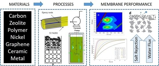
Substrate Effect on Carbon/Ceramic Mixed Matrix Membrane Prepared by a Vacuum-Assisted Method for Desalination

1
The University of Queensland, FIM2Lab—Functional Interfacial Materials and Membranes Laboratory, School of Chemical Engineering, Brisbane, QLD 4072, Australia
2
School of Chemical and Biomolecular Engineering, The University of Sydney, Darlington, NSW 2006, Australia
3
The University of Queensland, School of Chemical Engineering, Brisbane, QLD 4072, Australia
*
Author to whom correspondence should be addressed.
Processes 2018, 6(5), 47; https://doi.org/10.3390/pr6050047
Submission received: 30 March 2018 / Revised: 23 April 2018 / Accepted: 25 April 2018 / Published: 1 May 2018
(This article belongs to the Special Issue Membrane Materials, Performance and Processes)

Abstract

:
This work investigates the effect of various membrane substrates and coating conditions on the formation of carbon/ceramic mixed matrix membranes for desalination application. The substrates were impregnated with phenolic resin via a vacuum-assisted method followed by carbonization under an inert gas. Substrates with pore sizes of 100 nm required a single impregnation step only, where short vacuum times (<120 s) resulted in low quality membranes with defects. For vacuum times of ≥120 s, high quality membranes with homogeneous impregnation were prepared leading to high salt rejection (>90%) and high water fluxes (up to 25 L m−2 h−1). The increase in water flux as a function of the vacuum time confirms the vacuum etching effect resulting from the vacuum-assisted method. Substrates with pore sizes of 140 nm required two impregnation steps. These pores were too large for the ceramic inter-particle space to be filled with phenolic resin via a single step. In the second impregnation step, increasing the concentration of the phenolic resin resulted in membranes with lower water fluxes. These results indicate that thicker films were formed by increasing the phenolic resin concentration. In the case of substrates with pores of 600 nm, these pores were too large and inter-particle space filling with phenolic resin was not attained.

Graphical Abstract

1. Introduction

Access to water is one of the major problems facing many regions of the world, known as water poverty areas [1]. In these areas, water scarcity has led to several programs aiming to optimize water for agricultural use in Mali [2] and the Jordan Valley [3]; and policy integration in Cyprus [4] and Southern Africa [5]. A more concerning matter is access to potable water for human consumption, and desalting seawater technologies are employed around the world such as thermal processes [6,7,8], membrane distillation [9,10,11], and reverse osmosis membrane technology [12,13]. It is estimated that up to 25 million m3 of desalinated water is produced daily around the world [14], with large-scale desalination plants in the Middle East, particularly the United Arab Emirates, Kuwait, and Saudi Arabia [15]. Currently, reverse osmosis (RO) membrane is a leading technology to desalt sea water. RO membranes have also been reported for processing effluents from coal mining [16] and gold mining [17].
Inorganic membranes for desalination by pervaporation has attracted the attention of the research community in the last decade. An advantage of inorganic membranes in this application is operating at atmospheric feed pressure whilst processing high concentration brines (up to NaCl 15 wt %) [18], contrary to reverse osmosis (RO) membranes which require much higher feed pressures (60–75 bar) [19,20,21] and are only capable of processing waters with much lower salt concentrations (0.1 to 4.5 wt % NaCl [22]). The problem, however, is that inorganic membranes initially delivered very low water fluxes compared to RO membranes which deliver high water fluxes of 20–28 L m−2 h−1 [23]. Table 1 shows the water flux evolution for inorganic membranes including zeolite [24,25,26,27,28], silica [29,30,31,32], carbonized template silica [33,34,35,36,37], metal oxide silica [38,39,40], and titania [41] membranes, in addition to the novel carbon alumina mixed matrix inorganic membrane [42,43]. It is clear that observed water fluxes for inorganic membranes have increased significantly for the last decade. For instance, initial values of 0.2 and 1.4 L m−2 h−1 were reported in 2009 for zeolite and carbonized template silica membranes, respectively. By 2015, carbon alumina mixed matrix membranes achieved water fluxes of 9.4 L m−2 h−1, thus demonstrated improvements of almost two orders of magnitude as compared to the earlier embryonic results.
Much of the work in inorganic membranes has been dedicated to silica derived membranes. A variety of silica preparation methods have been reported, including changing the silica precursor or the pH of the preparation methods, adding carbon templates or metal oxides to the silica sol-gel. Lately, improved water fluxes have been achieved by preparing interlayer-free silica derived membranes, which have a lower resistance to water mass transfer than comparable membranes containing interlayers. Further, all these methods have delivered structural variations such as changes in pore size and porosity. As a consequence, due to the different silica membrane materials and structures, variations in the water fluxes from 1.4 to 9.5 L m−2 h−1 can be observed as demonstrated in Table 1. Moreover, the embedding of carbon templates into silica membranes followed by carbonization generally improved the long-term performance of the membranes. As carbon imparts hydrophobic properties, it provides a superior structural integrity to the hydrophilic and unstable silica. In addition, Elma and co-workers [35] reported that the water fluxes of carbonized template silica membranes were less affected by changes in feed salt concentration than pure silica. This was attributed to the carbon structure repelling hydrated ions, contrary to silica that adsorbs hydrated salt ions [44] and adds extra resistance to water transport.
Zeolite based membranes have also shown major improvement in water fluxes from 0.2 to 3.6 L m−2 h−1 in the last decade. Despite this improvement, the performance of zeolite membranes is still uncompetitive as compared to other inorganic membranes. Pure ceramic membrane reports for desalination are limited, particularly since ceramics membranes have large macropores and are often hydrophilic (dp > 50 nm) which cause pore wetting and low salt rejection. In the case of the titania membrane, the pore size was controlled to mesoporous dimensions of 4 nm where pore wetting was not observed [41]. Pore wetting is undesirable in pervaporation as the salt solutions fully diffuse through the pore structure of the membrane without any capacity to reject salt ions.
Recently, by combining carbon structures with alumina substrates, Song et al. pioneered a method of phenolic resin impregnation into an alumina substrate by a vacuum-assisted method [42]. The vacuum-assisted method conferred controlled pore sizes for desalination using pervaporation, in addition to molecular weight cut-off pore tailoring [45,46]. Carbon precursors are excellent materials for pore size tailoring under controlled pyrolysis (i.e., polymer carbonization) [47,48,49], including the preparation of mixed matrix membranes containing carbonised polymer and an inorganic phase [50,51]. Phenolic resin is a carbon precursor of interest for the preparation of high quality carbon membranes [52,53,54] or as composite alumina carbon membranes [55,56,57,58] after pyrolysis. All these carbon membranes were prepared as films for gas separation, and generally display low water fluxes in pervaporation due to ultra-micropore sizes. However, the vacuum-assisted method etched the thick-film into a thin-film whilst slightly opening the pore sizes, and thus improving water fluxes [43], which is desirable for desalination applications [59].
Within the limited reports on carbon alumina mixed matrix membranes for desalination under pervaporation conditions, the focus has been on the effect of the carbonisation temperature and vacuum-assisted time on membrane properties and performance correlation using a single substrate type only. As the vacuum-assisted method involves the impregnation of phenolic resin within the substrate structure, it warrants a detailed understanding of the role played by the substrate in the formation of carbon alumina mixed matrix membranes. Therefore, this work investigates the effect of alumina and titania substrates with pore sizes ranging from 100 to 600 nm on phenolic resin interparticle filling. In addition, the effect of the vacuum time, number of impregnation steps and feed phenolic resin concentration are studied and correlated to the membrane performance. The membranes are assessed for desalination using pure water and saline waters ranging from brackish (NaCl 0.3 and 1.0 wt %) to seawater (NaCl 3.5 wt %) concentrations at room temperature to 75 °C.

2. Experimental

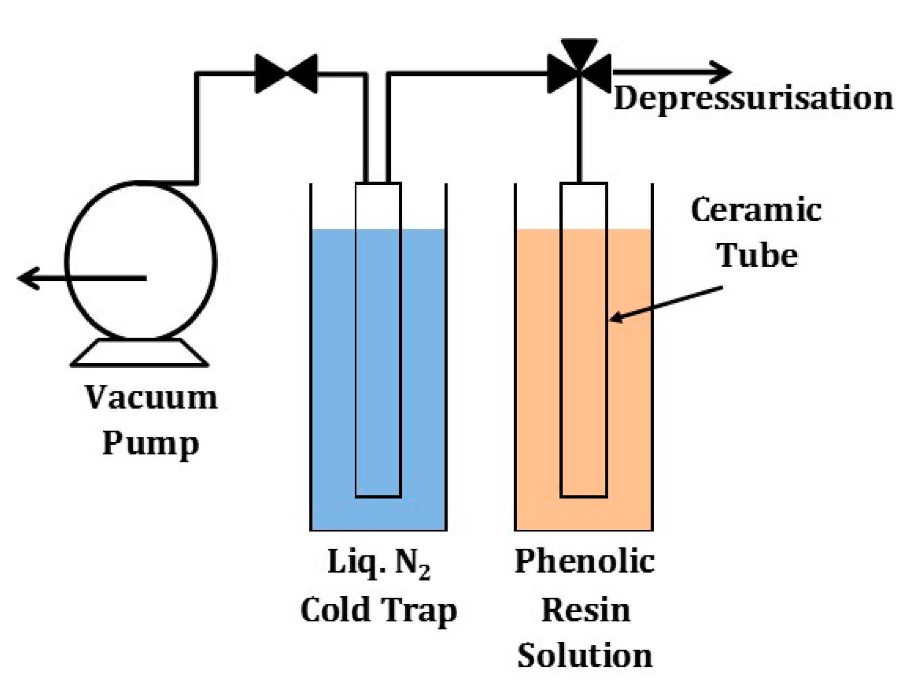
2.1. Membrane Preparation and Characterisation

A solution containing a phenolic resin Novolak Resinox IV-1058 was initially mixed with an appropriate amount of hexamine as a curing agent to ensure polycondensation between the phenolic resin and formaldehyde take place [60,61]. In order to obtain a solution with a consistent viscosity for coating substrates, the solution as diluted with methanol at a ratio of 1:99 wt %. The phenolic resin solution was impregnated into the substrate using a vacuum-assisted dip-coating method pioneered by Song and co-workers [42] as schematically shown in Figure 1. In this method, the outer shell of a porous ceramic tube was inserted in a beaker containing a phenolic resin. Then a vacuum (<1 Torr) was applied in the inner shell of the tube, allowing the impregnation of the phenolic resin into the porous substrate. The tube was exposed up to 600 s of vacuum impregnation time followed by a fast withdrawal from the solution in the beaker and rapid depressurisation of the inner shell to atmospheric pressure. Subsequently, the coated ceramic tubes were air dried for 24 h, and vacuum-dried for another 24 h. The final step of this preparation method was the pyrolysis of the coated ceramic tube up to 700 °C under an inert nitrogen atmosphere with a heating and cooling rate of 5 °C min-1 and a dwell time of 1 h. A series of membranes were prepared by using different substrates as listed in Table 2.

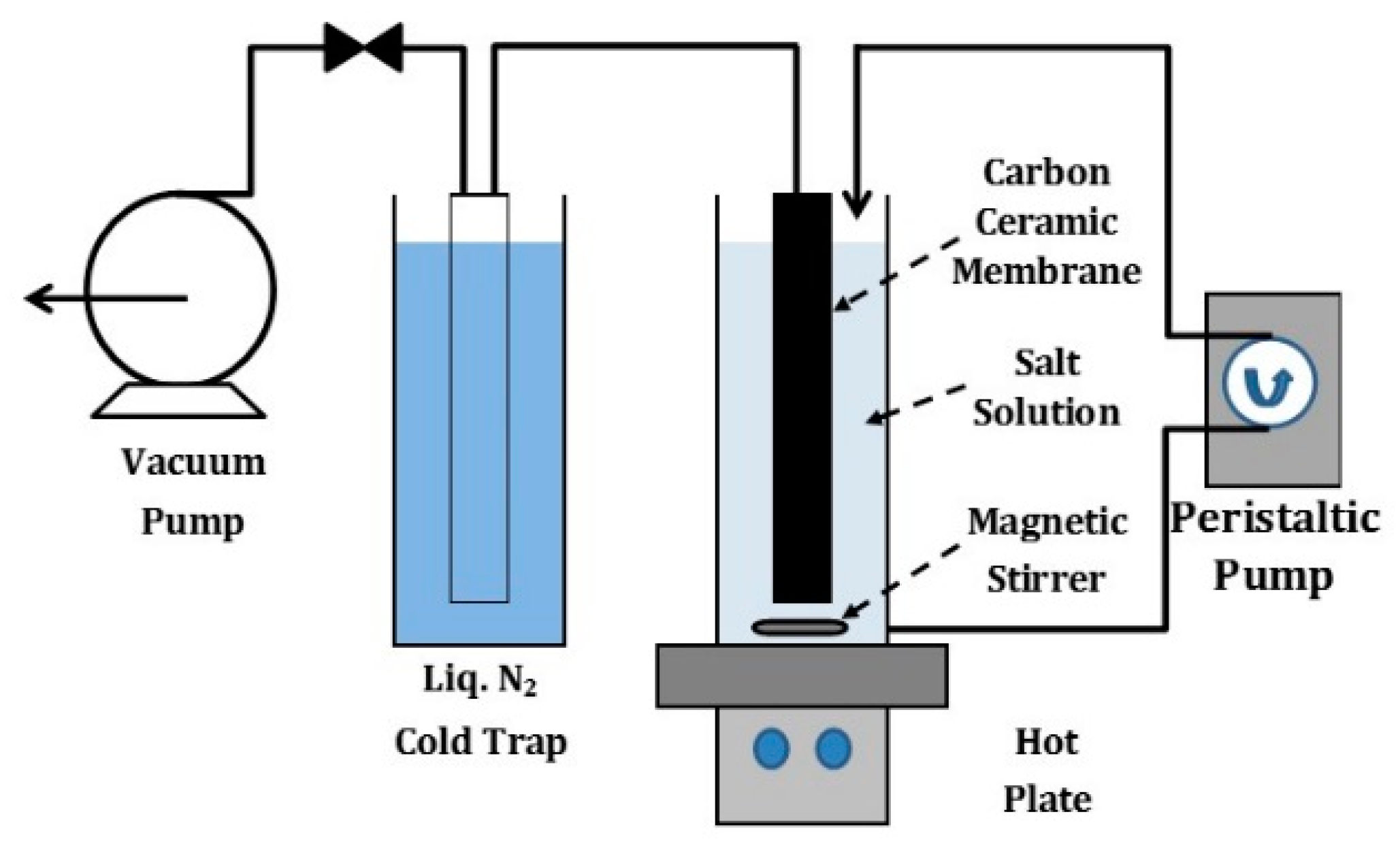
2.2. Membrane Testing and Characterisation

The membranes were tested for desalination using a pervaporation setup, shown schematically in Figure 2. The outer shell of the membrane tube was exposed to a feed salt water solution in a beaker. Feed solutions were prepared by dissolving an appropriate amount of NaCl (Sigma Aldrich, St. Louis, MO, USA) into deionised water, with NaCl concentrations ranging from 0.3 to 3.5 wt %. In this pervaporation set up, the driving force for water permeation through the membrane was provided by a vacuum pump in the inner shell of the tube. The water vapour permeated through the membrane was collected in a cold trap using liquid nitrogen. In order to minimise concentration polarisation, the NaCl was recirculated using a peristaltic pump, whilst the feed salt solution was stirred constantly in the beaker.
The water flux was calculated as J = (m/ρ) × (A × t), where J (L m−2 h−1) is the flux, m (kg) is the mass of water from the cold trap, ρ is the density of water (kg L−1), A is the membrane surface area (m2), and t (h) is the time over a testing period. The salt concentration in the water collected in the cold trap was analysed using a conductivity meter (LabCHEM CP). The conductivity of the samples was checked against calibrated salt concentration versus conductivity curves. The salt rejection was calculated as R = (Cf − Cr)/Cf × 100% based on conductivity of solutions, where R (%) is the salt rejection, Cf and Cp are the salt concentrations (NaCl wt %) in the feed and permeate streams, respectively. The feed temperature effect on water fluxes and salt rejection was also studied. The beaker containing the salt solution was placed on a hot plate where the temperature of the feed solution was controlled and varied from 20 to 75 °C.

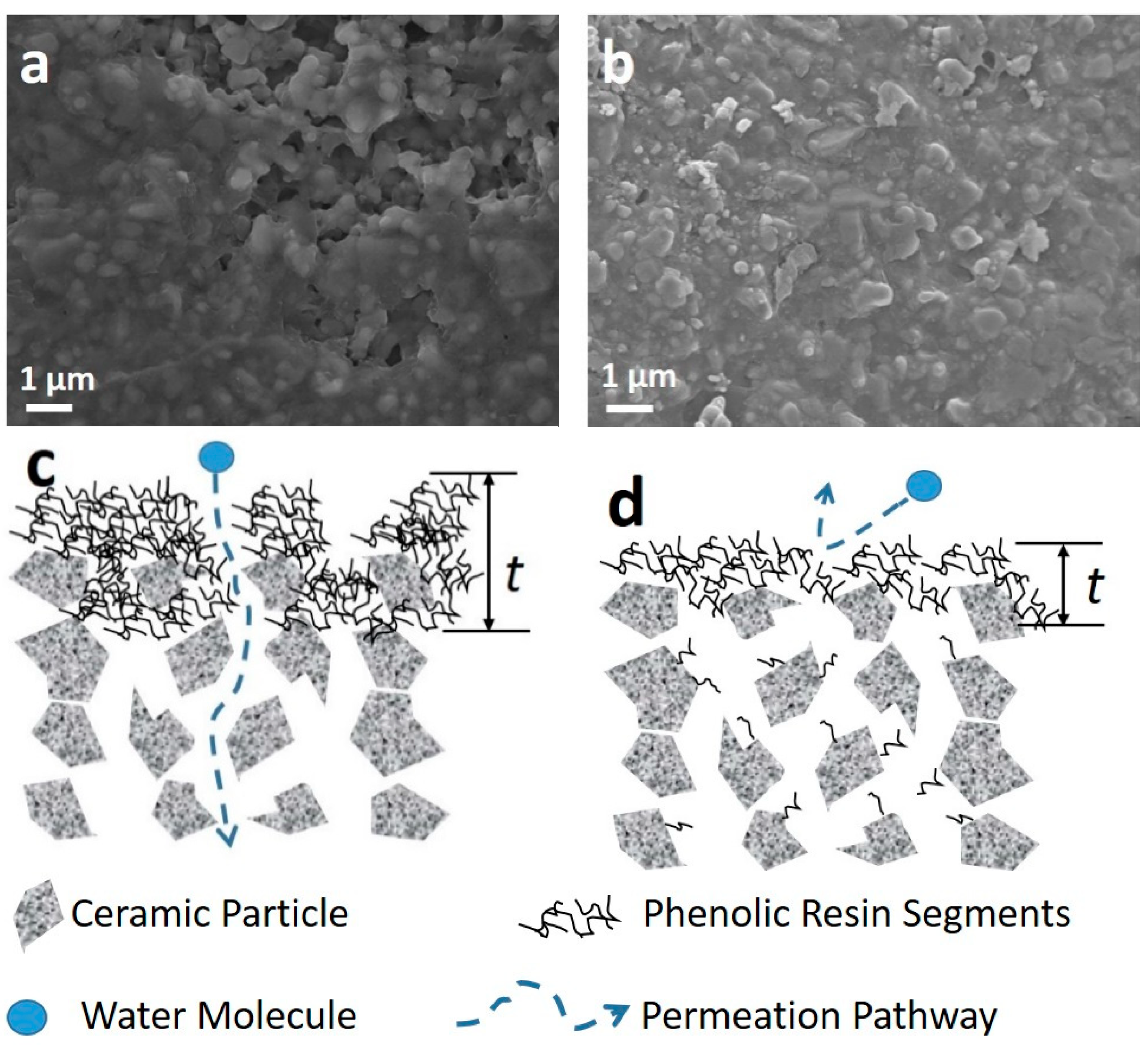
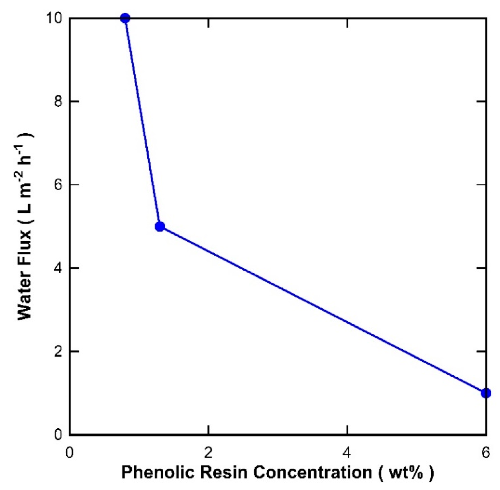
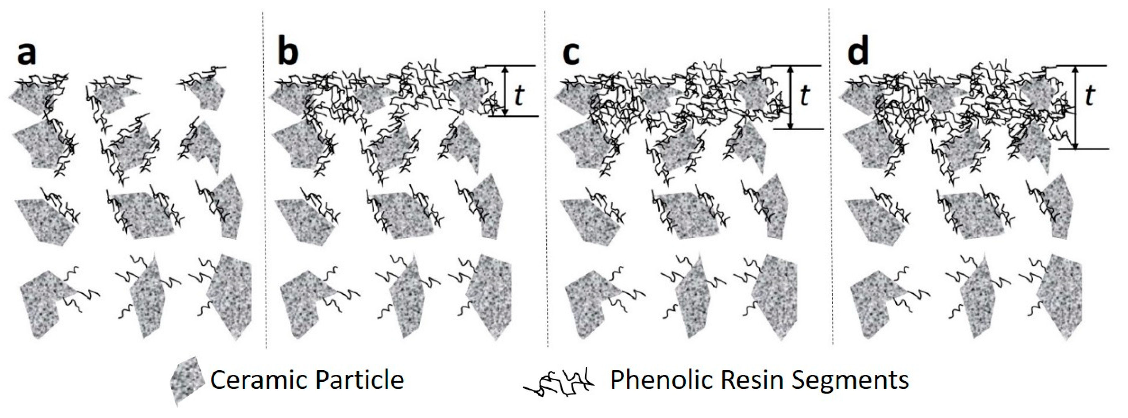
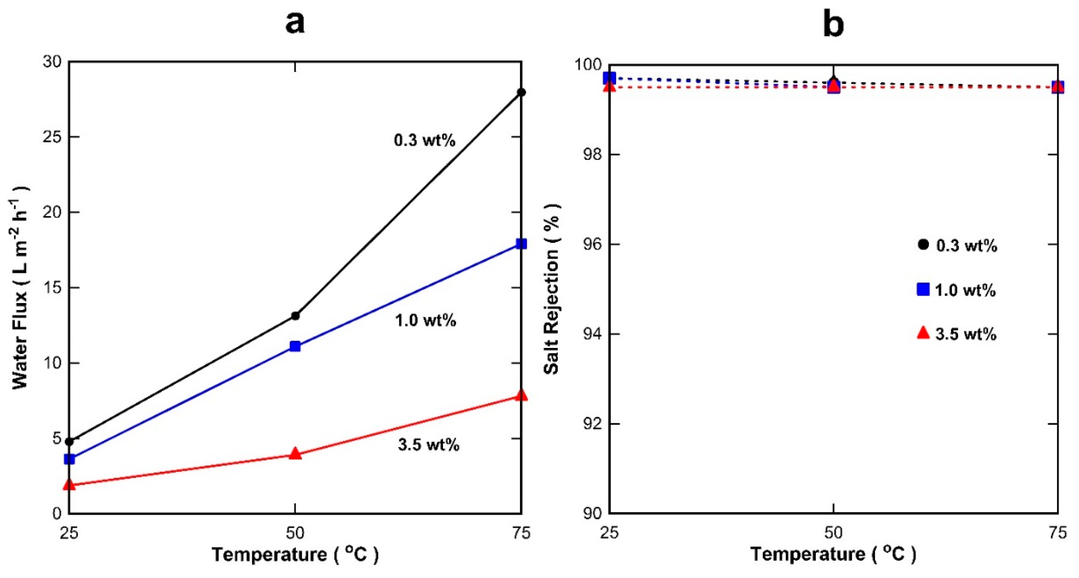
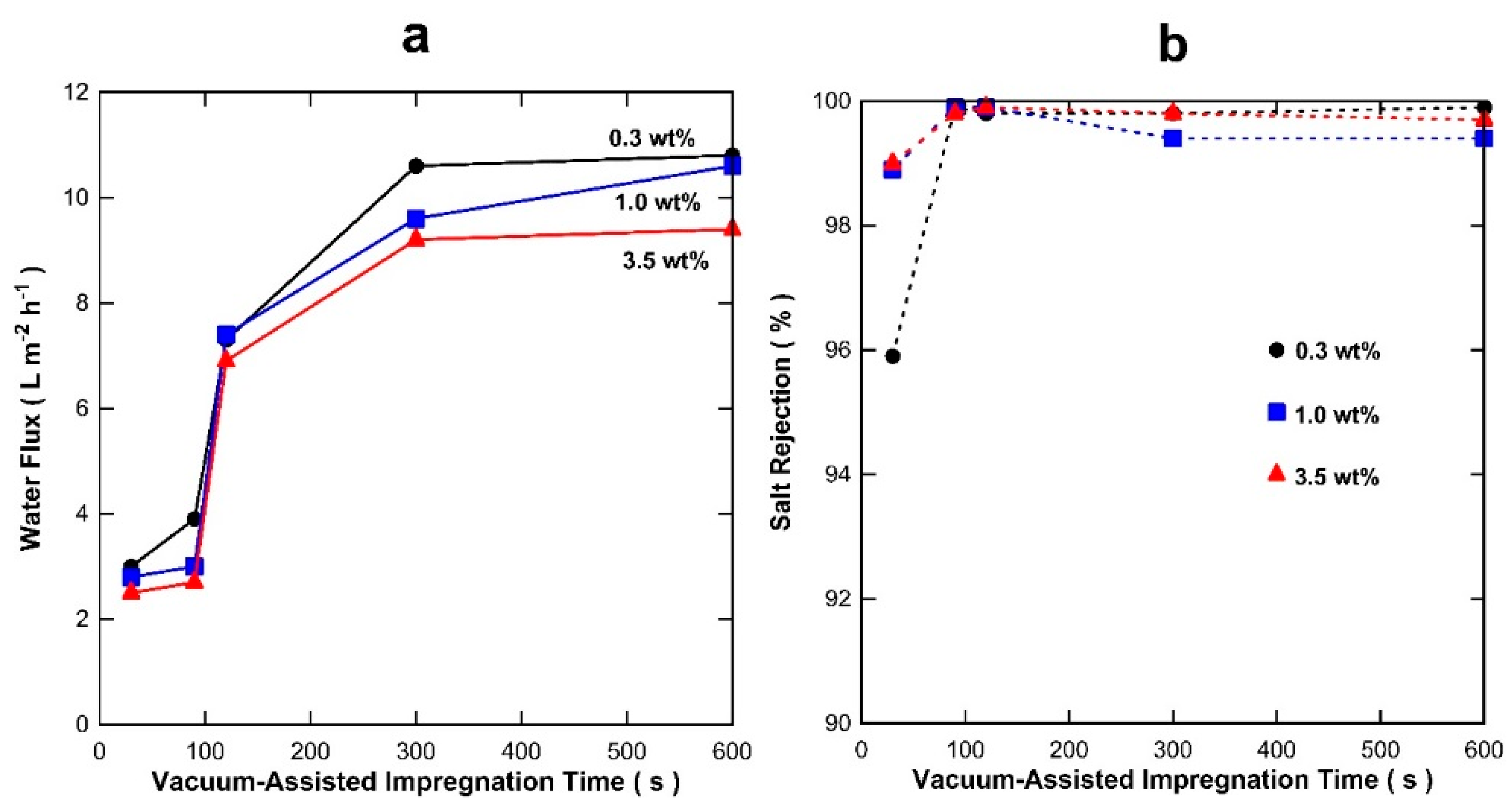
3. Results and Discussion

Membranes prepared using the S-C substrates (hereinafter S-C membranes) were initially prepared and tested as a function of the vacuum-assisted impregnation time (or vacuum time exposure) and results are displayed in Figure 3a for various feed solution of NaCl from 0.3 to 3.5 wt % tested at 20 °C. It is observed that the highest water fluxes were achieved by the membranes with a long vacuum exposure time. The water flux trends show stabilization around a vacuum exposure time of 300 s for all NaCl feed solutions. It is also observed in Figure 3a that the water flux slightly reduces as the NaCl feed concentration increased from 0.3 to 3.5 wt %, though the water flux reduction was relatively low as compared to silica derived membranes also for desalination applications [38]. Figure 3b shows that salt rejection was generally high in excess of 99%, except for the membranes prepared with 30 s vacuum-assisted time. NaCl cannot evaporate under the testing temperatures in this work. Hence, the presence of NaCl in the collected water from the cold trap is associated with hydrated ions entrained in water vapour droplet permeation through the membrane.
Figure 4a and 4b display the SEM surface images for the membranes prepared with vacuum-assisted times of 30 and 600 s. It is observed that the 30 s time exposure resulted in a surface coverage with large pores and partial coverage only. These observations suggest that 30 s vacuum-assisted time resulted in an uneven impregnation of phenolic resin as schematically shown in Figure 4c. Hence, large pores could not separate hydrated ions from water, thus explaining the lower salt rejection as compared with the membranes prepared with longer vacuum-assisted time. In addition, the 30 s vacuum exposure was too short to etch the phenolic resin segments, thus providing a thicker film with high resistance to water transport and lower water fluxes (see Figure 3a). Contrary to these trends, the membrane exposed to a vacuum-assisted time of 600 s resulted in a more even surface coverage as shown in Figure 4b. The schematic in Figure 4d depicts a more even surface coverage where the vacuum exposure time was enough to etch the phenolic resin segments and reducing the effective thickness of the carbon film as compared to the short 30 s vacuum time exposure. This is attributed to etching mechanism due to vacuum low pressure. In this mechanism, the effective thickness of the carbon film is reduced by a (re)dissolution of resin fragments which become entrained in the solvent and result in (re)deposition deeper into the substrate. The reduction of the effective thickness due to this etching mechanism thus explains the improved water fluxes as a function of the vacuum time exposure.
The S-T membranes could not process saline water due to pore wetting and resulted in no salt rejection. This is associated with the relatively large pore size of the interlayer film (~140 nm). In order to further verify the effect of the pore size on the formation of carbon membranes, a second impregnation was carried out by increasing the concentration of the resin from 1 to 10 wt %. The membranes were initially tested for pure water only. Figure 5 shows that the water fluxes reached 6.0, 1.3, and 0.8 L m−2 h−1 for the seconded coated membranes with 1, 5, and 10 wt % resin concentrations, respectively. These results show that the water flux decreased by almost one order of magnitude as the concentration of the phenolic resin solution was increased from 1 to 10 wt %. Hence, the higher the phenolic resin concentration, the higher is the transport resistance for water permeation through the membrane.
Figure 6 depicts a schematic of the S-T membrane impregnation process. As the pores of the support are relatively large, the first impregnation coat still resulted in relatively large pores (Figure 5a). In this process, phenolic resin segments were entrained in the solvent into the S-T substrate. This resulted in the coating of the titania particles, where the inter-particle space could not be filled by the phenolic resin. However, in the second coating step, the inter-particle space was able to be filled. As the concentration of the phenolic resin increased from 1% (Figure 6b), to 5% (Figure 6c) and 10% (Figure 6d), so did the effective thickness (t) of the impregnated membrane. The increase of the effective thickness as a function of the high resin concentration conferred higher resistance for the permeation of water, thus explaining the reduction of water fluxes from 6.0 to 0.8 L m−2 h−1 as the resin concentration increased from 1 to 10 wt %, respectively.
In view of the best performance of the S-T membrane containing two coats of 1 wt % phenolic resin, further tests were carried out with NaCl feed concentrations varying from 0.35 to 3.5 wt % as displayed in Figure 7a. It is notable that the water flux increased from 5 to 28 L m−2 h−1 as temperature increased from 25 to 75 °C for 0.3 wt %. This is attributed to the increase in the driving force. This is a characteristic of membranes with a transport mechanism (J = KΔ) where water vapour pressure (Δ) is the driving force for the water flux (J) through the membrane and K is a permeance coefficient K, which is in turn temperature dependent as reported elsewhere [62]. Therefore, raising the feed solution temperature results in increasing the water vapour pressure in the feed side. As the permeate side water vapour pressure is low due to the vacuum pressure, raising the temperature explains the observed increase in water fluxes. The increase of feed concentration from brackish (0.3 wt %) to sea water (3.5 wt %) led to a significant decrease in water fluxes, particularly as the temperature increased. This cannot be attributed to the changes in vapour pressure, which does not change significantly for the same temperature as a function of the salt concentration [63]. This result could be related to the effect of the hydrophilic titania particles, which could not be fully covered during the two-step vacuum-assisted impregnation applied to the S-T substrates. In Figure 7b, the membrane shows excellent salt rejections of >99.5% in all the testing conditions, demonstrating the feasibility of the two-coating method.
S-P membranes with 600 nm pore size were prepared in triplicate but failed to deliver any salt rejection. Even though a second impregnation coating was also applied with different resin concentration from 1 to 10%, this strategy did not yield desalted water. In all cases, pore wetting was observed as the solution went through the membrane unimpeded. This problem was attributed to the very large 600 nm pores of the S-P substrates, which does not allow the effective carbon structural formation within the alumina pores, similar to Figure 5a. This problem results in pore wetting and the undesirable diffusion of hydrated salts.
Figure 8 shows a comparison of the water flux versus salt rejection based on the data in Table 1 and the results in the work. It is observed that a large number of membranes are now reaching a high level of water purity as salt rejections are higher than 99%. Further, water fluxes increased as a function of the salt rejection, clearly indicating that membrane preparation processes greatly improved with superior control of pore sizes and reduction of thin film thickness. Compared with the results in the literature, the results in this work are reaching the highest water fluxes and salt rejections. In addition, the carbon/ceramic mixed matrix membrane proved to be very stable as each point in Figure 7 corresponds to one day of full testing. Hence, the membrane was tested for over 200 h at 9 points of temperature and feed salt concentration, and consistently delivered very high salt rejections.
Finally, carbon/ceramic mixed matrix membranes may find several industrial applications. The most obvious is in desalination, particularly for waters with high salinity concentration, such as brines [64]. This is important for industries which require compliance with zero liquid discharge [65] where water must be recovered and re-used again. One clear example is the coal seam gas industry in Australia, where coal seam gas water is no longer allowed to be simply disposed of in evaporation ponds. Australia is one of driest continents in the world, and according to new policies [66], there is a need to beneficially use the coal seam water to protect the environment and water as a valuable resource. Other potential applications of the membranes in this work are for the novel percrystallisation processes [67] for a number of industrial projects, such as hydrometallurgy by crystallising mineral salts, or for pharmaceuticals by crystallising important compounds for health therapy.

4. Conclusions

The vacuum-assisted method proved to be effective in preparing mixed matrix membranes containing carbon/alumina or carbon/titania for desalination applications. Short vacuum times formed membranes with more surface defects, whilst longer vacuum time allowed for a more even surface coverage. The substrate structure played a role in the final vacuum-impregnation method. Substrate with pore sizes of 100 nm only required a single vacuum-assisted impregnation step. Substrates with pores of ~140 nm required two impregnation steps. By increasing the concentration of the phenolic resin in the second impregnation step, the water fluxes reduced. These results suggested that the resin concentration increased the effective film thickness and compactness of the carbon/alumina mixed matrix film, thus adding extra resistance for the transport of water. In the case of pores being too large (>600 nm), the vacuum-assisted method did not fill the interparticle space of the substrate and impregnated membrane films could not be formed. Future potential applications could include processing brines, water recovery for compliance with zero liquid discharge policies, and percrystallisation membranes in hydrometallurgy and pharmaceutical industries.

Author Contributions

Y. Song carried out all experimental work. J. Motuzas provided the SEM images and analysis. D.K. Wang, G. Birkett, S. Smart and J.C. Diniz da Costa supervised the project and provided research directions. All authors contributed to the drafting of this paper.

Acknowledgments

The authors would like to acknowledge funding support from the Australian Research Council (ARC) through Discovery Project Grant DP140102800. Y. Song also acknowledges funding support from The University of Queensland in providing a UQ International Scholarship. D.K. Wang and J.C. Diniz da Costa gratefully thank the support given by the ARC via the Discovery Early Career Researcher Award (DE150101687) and Future Fellowship Program (FT130100405), respectively.

Conflicts of Interest

The authors declare no conflict of interest.

References

  1. Thakur, J.K.; Mahesh Neupane, M.; Mohanan, A.A. Water poverty in upper Bagmati River Basin in Nepal. Water Sci. 2017, 31, 93–108. [Google Scholar] [CrossRef]
  2. Gumma, M.K.; Birhanu, B.Z.; Mohammed, I.A.; Tabo, R.; Whitbread, A.M. Prioritization of watersheds across Mali using remote sensing data and GIS techniques for agricultural development planning. Water 2016, 8, 260. [Google Scholar] [CrossRef] [Green Version]
  3. Al-Mashaqbeh, O.A.; Ghrair, A.M.; Megdal, S.B. Grey water reuse for agricultural purposes in the Jordan Valley: Household survey results in Deir Alla. Water 2012, 4, 580–596. [Google Scholar] [CrossRef]
  4. Sofroniou, A.; Bishop, S. Water scarcity in Cyprus: A review and call for integrated policy. Water 2014, 6, 2898–2928. [Google Scholar] [CrossRef]
  5. Mabhaudhi, T.; Mpandeli, S.; Madhlopa, A.; Modi, A.T.; Backeberg, G.; Nhamo, L. Southern Africa’s water—energy nexus: Towards regional integration and development. Water 2016, 8, 235. [Google Scholar] [CrossRef]
  6. Hamed, O.A.; Al-Sofi, M.A.K.; Imam, M.; Mustafa, G.M.; Mardouf, K.B.; Al-Washmi, H. Thermal performance of multi-stage flash distillation plants in Saudi Arabia. Desalination 2000, 128, 281–292. [Google Scholar] [CrossRef]
  7. Attia, A.A.A.; Abdel-Rehim, A.A. Thermal analysis for system uses pressurized hot water for seawater desalination (pressurized multistage). Desalination 2014, 346, 91–99. [Google Scholar] [CrossRef]
  8. Said, S.A.; Emtir, M.; Mujtaba, I.M. Flexible design and operation of multi-stage flash (MSF) desalination process subject to variable fouling and variable freshwater demand. Processes 2013, 1, 279–295. [Google Scholar] [CrossRef]
  9. Ullah, R.; Khraisheh, M.; Esteves, R.J.; McLeskey, J.T.; AlGhouti, M.; Gad-el-Hak, M.; Tafreshi, H.V. Energy efficiency of direct contact membrane distillation. Desalination 2018, 433, 56–67. [Google Scholar] [CrossRef]
  10. Silva, T.L.S.; Morales-Torres, S.; Esteves, C.M.P.; Ribeiro, A.R.; Nunes, O.C.; Figueiredo, J.L.; Silva, A.M.T. Desalination and removal of organic micropollutants and microorganisms by membrane distillation. Desalination 2018, 437, 121–132. [Google Scholar] [CrossRef]
  11. Singh, D.; Sirkar, K.K. Performance of PVDF flat membranes and hollow fibers in desalination by direct contact membrane distillation at high temperatures. Sep. Purif. Technol. 2017, 187, 264–273. [Google Scholar] [CrossRef]
  12. Blandin, G.; Verliefde, A.R.D.; Comas, J.; Rodriguez-Roda, I.; Le-Clech, P. Efficiently combining water reuse and desalination through Forward Osmosis—Reverse Osmosis (FO-RO) Hybrids: A Critical Review. Membranes 2016, 6, 37. [Google Scholar] [CrossRef] [PubMed]
  13. Subramani, A.; Jacangelo, J.G. Treatment technologies for reverse osmosis concentrate volume minimization: A review. Sep. Purif. Technol. 2014, 122, 472–489. [Google Scholar] [CrossRef]
  14. Lattemann, S.; Höpner, T. Environmental impact and impact assessment of seawater desalination. Desalination 2008, 220, 1–15. [Google Scholar] [CrossRef]
  15. Roberts, D.A.; Johnston, E.L.; Knott, N.A. Impacts of desalination plant discharges on the marine environment: A critical review of published studies. Water Res. 2010, 44, 5117–5128. [Google Scholar] [CrossRef] [PubMed]
  16. Thiruvenkatachari, R.; Francis, M.; Cunnington, M.; Su, S. Application of integrated forward and reverse osmosis for coal mine wastewater desalination. Sep. Purif. Technol. 2016, 163, 181–188. [Google Scholar] [CrossRef]
  17. Ricci, B.C.; Ferreira, C.D.; Marques, L.S.; Martins, S.S.; Reis, B.G.; Amaral, M.C.S. Assessment of the chemical stability of nanofiltration and reverse osmosis membranes employed in treatment of acid gold mining effluent. Sep. Purif. Technol. 2017, 174, 301–311. [Google Scholar] [CrossRef]
  18. Elma, M.; Yacou, C.; Wang, D.K.; Smart, S.; Diniz da Costa, J.C. Microporous Silica Based Membranes for Desalination. Water 2012, 4, 629–649. [Google Scholar] [CrossRef]
  19. Greenlee, L.F.; Lawler, D.F.; Freeman, B.D.; Marrot, B.; Moulin, P. Reverse osmosis desalination: Water sources, technology, and today’s challenges. Water Res. 2009, 43, 2317–2348. [Google Scholar] [CrossRef] [PubMed]
  20. Kurihara, M.; Takeuchi, H. SWRO-PRO System in “Mega-ton Water System” for Energy Reduction and Low Environmental Impact. Water 2018, 10, 48. [Google Scholar] [CrossRef]
  21. Kurihara, M.; Sasaki, T.; Nakatsuji, K.; Kimura, M.; Henmi, M. Low pressure SWRO membrane for desalination in the “Mega-ton Water System”. Desalination 2015, 368, 135–139. [Google Scholar] [CrossRef]
  22. Fritzmann, C.; Lowenberg, J.; Wintgens, T.; Melin, T. State-of-the-art of reverse osmosis desalination. Desalination 2007, 216, 1–76. [Google Scholar] [CrossRef]
  23. Lee, K.P.; Arnott, T.C.; Mattia, D. A review of reverse osmosis membrane materials for desalination—Development to date and future potential. J. Membr. Sci. 2011, 370, 1–22. [Google Scholar] [CrossRef] [Green Version]
  24. Duke, M.C.; O’Brien-Abraham, J.; Milne, N.; Zhu, B.; Lin, J.Y.S.; Diniz da Costa, J.C. Seawater desalination performance of MFI type membranes made by secondary growth. Sep. Purif. Technol. 2009, 68, 343–350. [Google Scholar] [CrossRef]
  25. Cho, C.H.; Oh, K.Y.; Kim, S.K.; Yeo, J.G.; Sharma, P. Pervaporative seawater desalination using NaA zeolite membrane: Mechanisms of high water flux and high salt rejection. J. Memb. Sci. 2011, 371, 226–238. [Google Scholar] [CrossRef]
  26. Drobek, M.; Yacou, C.; Motuzas, J.; Julbe, A.; Ding, L.; Diniz da Costa, J.C. Long term pervaporation desalination of tubular MFI zeolite membranes. J. Memb. Sci. 2012, 415, 816–823. [Google Scholar] [CrossRef]
  27. Zhou, C.; Zhou, J.; Huang, A. Seeding-free synthesis of zeolite FAU membrane for seawater desalination by pervaporation. Microporous Mesoporous Mater. 2016, 234, 377–383. [Google Scholar] [CrossRef]
  28. Malekpour, A.; Nasiri, H. High performance pervaporative desalination of saline waters using Na-X zeolite membrane. Membr. Water Treatm. 2017, 8, 437–448. [Google Scholar]
  29. Elma, M.; Yacou, C.; Diniz da Costa, J.C.; Wang, D.K. Performance and Long Term Stability of Mesoporous Silica Membranes for Desalination. Membranes 2013, 3, 136–150. [Google Scholar] [CrossRef] [PubMed]
  30. Chua, Y.T.; Lin, C.X.C.; Kleitz, F.; Zhao, X.S.; Smart, S. Nanoporous organosilica membrane for water desalination. Chem. Commun. 2013, 49, 4534–4536. [Google Scholar] [CrossRef] [PubMed]
  31. Wang, S.; Wang, D.K.; Motuzas, J.; Smart, S.; Diniz da Costa, J.C. Rapid Thermal Treatment of Interlayer-free Ethyl Silicate 40 Derived Membranes for Desalination. J. Memb. Sci. 2016, 516, 94–103. [Google Scholar] [CrossRef]
  32. Wang, S.; Wang, D.K.; Smart, S.; Diniz da Costa, J.C. Improved stability of ethyl silicate interlayer-free membranes by the rapid thermal processing (RTP) for desalination. Desalination 2017, 402, 25–32. [Google Scholar] [CrossRef]
  33. Wijaya, S.; Duke, M.C.; Diniz da Costa, J.C. Carbonised template silica membranes for desalination. Desalination 2009, 236, 291–298. [Google Scholar] [CrossRef]
  34. Ladewig, B.P.; Tan, Y.H.; Lin, C.X.C.; Ladewig, K.; Diniz da Costa, J.C.; Smart, S. Preparation, Characterization and Performance of Templated Silica Membranes in Non-Osmotic Desalination. Materials 2011, 4, 845–856. [Google Scholar] [CrossRef] [PubMed]
  35. Elma, M.; Wang, D.K.; Yacou, C.; Diniz da Costa, J.C. Interlayer-Free P123 Carbonised Template Silica Membranes for Desalination with Reduced Salt Concentration Polarisation. J. Memb. Sci. 2015, 475, 376–383. [Google Scholar] [CrossRef]
  36. Yang, H.; Elma, M.; Wang, D.K.; Motuzas, J.; Diniz da Costa, J.C. Interlayer-free hybrid carbon-silica membranes for processing brackish to brine salt solutions by pervaporation. J. Memb. Sci. 2017, 523, 197–204. [Google Scholar] [CrossRef]
  37. Yang, H.; Wang, D.K.; Motuzas, J.; Diniz da Costa, J.C. Hybrid vinyl silane and P123 template sol−gel derived carbon silica membrane for desalination. J. Sol-Gel Sci. Technol. 2018, 85, 280–289. [Google Scholar] [CrossRef]
  38. Lin, C.X.C.; Ding, L.; Smart, S.K.; Diniz da Costa, J.C. Cobalt Oxide Silica Membranes for Desalination. J. Coll. Interface Sci. 2012, 368, 70–76. [Google Scholar] [CrossRef] [PubMed]
  39. Elma, M.; Wang, D.K.; Yacou, C.; Motuzas, J.; Diniz da Costa, J.C. High Performance Interlayer-Free Mesoporous Cobalt Oxide Silica Membranes for Desalination Applications. Desalination 2015, 365, 308–315. [Google Scholar] [CrossRef]
  40. Darmawan, A.; Karlina, L.; Astuti, Y.; Sriatun; Wang, D.K.; Diniz da Costa, J.C. Structural evolution of nickel oxide silica sol-gel for the preparation of interlayer-free membranes. J. Non-Cryst. Solids 2016, 447, 9–15. [Google Scholar] [CrossRef]
  41. Yacou, C.; Smart, S.; Diniz da Costa, J.C. Mesoporous TiO2 based membranes for water desalination and brine processing. Sep. Purif. Technol. 2015, 147, 166–171. [Google Scholar] [CrossRef]
  42. Song, Y.; Wang, D.K.; Birkett, G.; Martens, W.; Smart, S.; Diniz da Costa, J.C. Mixed Matrix Carbon Molecular Sieve and Alumina (CMS-Al2O3) Membranes for Desalination. Sci. Rep. 2016, 6, 30703. [Google Scholar] [CrossRef] [PubMed]
  43. Song, Y.; Wang, D.K.; Birkett, G.; Smart, S.; Diniz da Costa, J.C. Vacuum film etching effect of carbon alumina mixed matrix membranes. J. Memb. Sci. 2017, 541, 53–61. [Google Scholar] [CrossRef]
  44. De Lint, W.B.S.; Zivkovic, T.; Benes, N.E.; Bouwmeester, H.J.M.; Blank, D.H.A. Electrolyte retention of supported bi-layered nanofiltration membranes. J. Membr. Sci. 2006, 277, 18–27. [Google Scholar]
  45. Abd Jalil, S.N.; Wang, D.K.; Yacou, C.; Motuzas, J.; Smart, S.; Diniz da Costa, J.C. Vacuum-Assisted Tailoring of Pore Structures of Phenolic Resin Derived Carbon Membranes. J. Membr. Sci. 2017, 525, 240–248. [Google Scholar] [CrossRef]
  46. Abd Jalil, S.N.; Wang, D.K.; Yacou, C.; Motuzas, J.; Smart, S.; Diniz da Costa, J.C. Molecular Weight Cut-off and Structural Analysis of Vacuum-assisted Titania Membranes for Water Processing. Materials 2016, 9, 938. [Google Scholar] [CrossRef] [PubMed]
  47. Hamm, J.B.S.; Ambrosi, A.; Griebeler, J.G.; Marcilio, N.R.; Tessaro, I.C.; Pollo, L.D. Recent advances in the development of supported carbon membranes for gas separation. Int. J. Hydrog. Energy 2017, 42, 24830–24845. [Google Scholar] [CrossRef]
  48. Kiyono, M.; Williams, P.J.; Koros, W.J. Generalization of effect of oxygen exposure on formation and performance of carbon molecular sieve membranes. Carbon 2010, 48, 4442–4449. [Google Scholar] [CrossRef]
  49. Kim, S.J.; Park, Y.I.; Nam, S.E.; Park, H.; Lee, P.S. Separations of gases from nitrogen through thin carbon membranes. Sep. Purif. Technol. 2016, 158, 108–114. [Google Scholar] [CrossRef]
  50. Li, Y.-Y.; Nomura, T.; Sakoda, A.; Suzuki, M. Fabrication of carbon coated ceramic membranes by pyrolysis of methane using a modified chemical vapor deposition apparatus. J. Memb. Sci. 2002, 197, 23–35. [Google Scholar] [CrossRef]
  51. Schmeda-Lopez, D.R.; Smart, S.; Meulenberg, W.A.; Diniz da Costa, J.C. Mixed matrix carbon stainless steel (MMCSS) hollow fibres for gas separation. Sep. Purif. Technol. 2017, 174, 150–158. [Google Scholar] [CrossRef]
  52. Wei, W.; Qin, G.T.; Tang, P.J.; Wu, L.P. Effects of pyrolysis conditions on the permeance of phenol-formaldehyde resin based carbon membrane for CO2 separation. Adv. Mater. Res. 2011, 239–242, 1804–1808. [Google Scholar] [CrossRef]
  53. Wei, W.; Hu, H.; Qin, G.; You, L.; Chen, G. Pore structure control of phenol-formaldehyde based carbon microfiltration membranes. Carbon 2004, 42, 679–681. [Google Scholar] [CrossRef]
  54. Centeno, T.A.; Vilas, J.L.; Fuertes, A.B. Effects of phenolic resin pyrolysis conditions on carbon membrane performance for gas separation. J. Membr. Sci. 2004, 228, 45–54. [Google Scholar] [CrossRef]
  55. Teixeira, M.; Rodrigues, S.; Campo, M.C.; Pacheco Tanaka, D.A.; Llosa Tanco, M.A.; Madeira, L.; Sousa, J.; Mendes, A. Boehmite-phenolic resin carbon molecular sieve membranes—Permeation and adsorption studies. Chem. Eng. Res. Des. 2014, 92, 2668–2680. [Google Scholar] [CrossRef]
  56. Llosa Tanco, M.A.; Pacheco Tanaka, D.A.; Rodrigues, S.C.; Teixeira, M.; Mendes, A. Composite-alumina-carbon molecular sieve membranes prepared from novolac resin and boehmite. Part I: Preparation, characterization and gas permeation studies. Int. J. Hydrog. Energy 2015, 40, 5653–5663. [Google Scholar] [CrossRef]
  57. Llosa Tanco, M.A.; Pacheco Tanaka, D.A.; Mendes, A. Composite-alumina-carbon molecular sieve membranes prepared from novolac resin and boehmite. Part II: Effect of the carbonization temperature on the gas permeation properties. Int. J. Hydrog. Energy 2014, 40, 3485–3496. [Google Scholar] [CrossRef]
  58. Teixeira, M.; Campo, M.C.; Pacheco Tanaka, D.A.; Llosa Tanco, M.A.; Magen, C.; Mendes, A. Composite phenolic resin-based carbon molecular sieve membranes for gas separation. Carbon 2011, 49, 4348–4358. [Google Scholar] [CrossRef]
  59. Li, Q.; Chen, G.; Liu, L.; Wang, X. Fabrication of phenolic resin based desalting membrane with ordered mesostructure and excellent chlorine resistance. J. Membr. Sci. 2018, 550, 502–509. [Google Scholar] [CrossRef]
  60. Knop, A.; Scheib, W. Chemistry and Application of Phenolic Resins; Springer: New York, NY, USA, 1979. [Google Scholar]
  61. Knop, A.; Pilato, L.A. Phenolic Resins; Springer: New York, NY, USA, 1985. [Google Scholar]
  62. Lawson, K.W.; Lloyd, D.R. Membrane distillation. J. Membr. Sci. 1997, 124, 1–25. [Google Scholar] [CrossRef]
  63. Sparrow, B.S. Empirical equations for the thermodynamic properties of aqueous sodium chloride. Desalination 2003, 159, 161–170. [Google Scholar] [CrossRef]
  64. Edwi, F.; Chung, T.-S. Development of hollow fiber membranes for water and salt recovery from highly concentrated brine via direct contact membrane distillation and crystallization. J. Membr. Sci. 2012, 421, 111–123. [Google Scholar] [CrossRef]
  65. Ali, A.; Drioli, D.; Macedonio, F. Membrane engineering for sustainable development: a perspective. Appl. Sci. 2017, 7, 1026. [Google Scholar] [CrossRef]
  66. Department of Environment and Heritage Protection. Coal Seam Gas Water Management Policy; Department of Environment and Heritage Protection: Brisbane, Australia, 2012.
  67. Motuzas, J.; Yacou, C.; Madsen, R.S.K.; Fu, W.; Wang, D.K.; Julbe, A.; Vaughan, J.; Diniz da Costa, J.C. Novel inorganic membrane for the percrystallization of mineral, food and pharmaceutical compounds. J. Membr. Sci. 2018, 550, 407–415. [Google Scholar] [CrossRef]
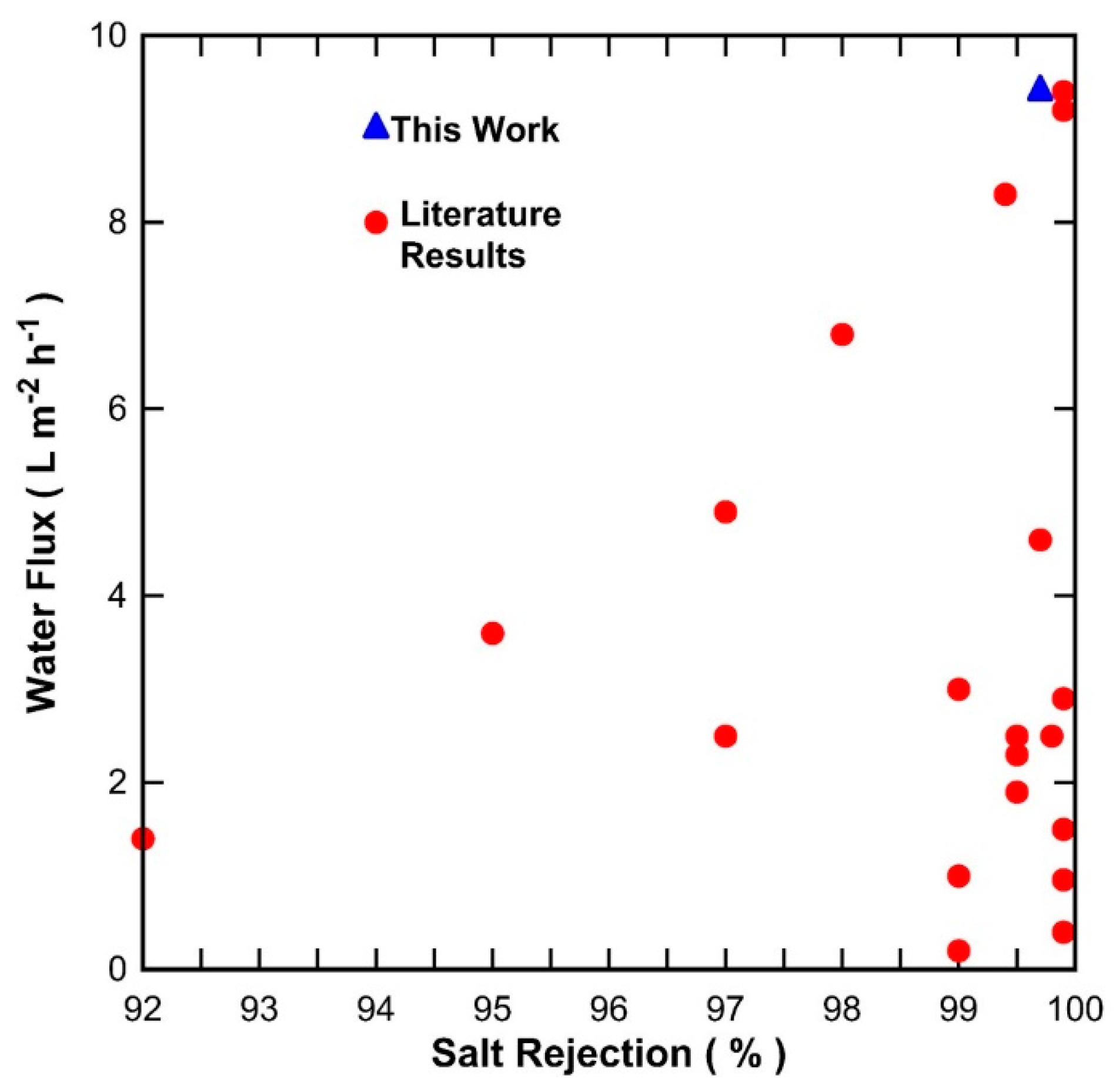
Figure 1. Schematic of the vacuum-assisted impregnation method.
Processes 06 00047 g001
Figure 2. Schematic of the pervaporation experimental set up.
Processes 06 00047 g002
Figure 3. S-C membrane results as a function of the vacuum-assisted impregnation time for (a) water flux (±8%) and (b) salt rejection (±1%) at 20 °C and various NaCl feed concentrations.
Processes 06 00047 g003
Figure 4. Representative SEM images of the surface of carbon alumina S-C membranes prepared at vacuum-assisted impregnation times of (a) 30 s and (b) 600 s, and respective idealized membrane structural schematic (c) 30 s and (d) 600 s and the phenolic resin thickness (t).
Processes 06 00047 g004
Figure 5. Pure water flux (±8%) of membranes impregnated with phenolic resin of 1 wt % in the first-step and varying phenolic resin concentration in the second step.
Processes 06 00047 g005
Figure 6. Idealized schematic of the vacuum-assisted phenolic impregnation method for the S-T substrates (a) first impregnation, and second impregnation for phenolic resin concentrations of (b) 1 wt %, (c) 5 wt %, and (d) 10 wt % and the phenolic resin thickness (t).
Processes 06 00047 g006
Figure 7. Desalination results for membrane S-T-1% (first coat) and -1% (second coat) (a) water fluxes (±8%) and (b) salt rejection (±1%).
Processes 06 00047 g007
Figure 8. Water flux versus salt rejection of results in Table 1 and the membrane S-C membrane with a 600 s vacuum exposure in this work. All results are for feed solutions of NaCl 3.5 wt % at room temperature.
Processes 06 00047 g008
Table 1. Review results of inorganic membranes reported for desalination tested at NaCl ~3.5 wt % and room temperature.
TimelineMembraneFlux (L m−2 h−1)Rejection (%)Reference
2009Zeolite MFI-ZSM-50.299Duke et al. [24]
2011Zeolite NaA0.499.9Cho et al. [25]
2012Zeolite MFI-S1199Drobek et al. [26]
2016Zeolite Fau0.9699.9Zhou et al. [27]
2017Zeolite NaA-X3.695Malekpour et al. [28]
2013Pure silica6.898Elma et al. [29]
2013Ordered hybrid SiO22.999.9Chua et al. [30]
2016* RTP pure silica pH4 sol-gel2.599.5Wang et al. [31]
2017* RTP pure silica pH1 sol-gel1.999.5Wang et al. [32]
2009C6 silica1.492Wijaya et al. [33]
2011PEG-PPG4.997Ladewig et al. [34]
2015Silica P1232.399.5Elma et al. [35]
2017Carbonised template8.399.4Yang et al. [36]
2018Carbonised template2.599.8Yang et al. [37]
2012cobalt oxide silica1.599.9Lin et al. [38]
2015cobalt oxide silica4.699.7Elma et al. [39]
2016nickel oxide silica2.597Darmwan et al. [40]
2015Titania3>99Yacou et al. [41]
2016carbon alumina 9.499.9Song et al. [42]
2017carbon alumina9.299.9Song et al. [43]
* RTP—Rapid Thermal Treatment.
Table 2. Substrates used for the preparation of carbon membranes.
SubstrateSupplierSubstrate Material, Pore Size and Dimensions
S-CCeramic Fabricatorsα-Al2O3, dp = ~100 nm
Dimensions: OD 9 mm ID 6 mm
S-TTAMITiO2 substrate and top layer, dp = ~140 nm
Dimensions: OD 10 mm, ID 6 mm
S-PPallα-Al2O3, dp = ~600 nm
Dimensions: OD 10 mm ID 6.5 mm

