Key Parameters of Gob-Side Entry Retaining in A Gassy and Thin Coal Seam with Hard Roof


1
Key Laboratory of Deep Coal Resource Mining (CUMT), Ministry of Education, Xuzhou 221116, China
2
School of Mines, China University of Mining & Technology, Xuzhou 221116, China
*
Author to whom correspondence should be addressed.
Processes 2018, 6(5), 51; https://doi.org/10.3390/pr6050051
Submission received: 4 April 2018
/
Revised: 3 May 2018
/
Accepted: 3 May 2018
/
Published: 7 May 2018
(This article belongs to the Special Issue Fluid Flow in Fractured Porous Media)
Abstract
:Gob-side entry retaining (GER) employed in a thin coal seam (TCS) can increase economic benefits and coal recovery, as well as mitigate gas concentration in the gob. In accordance with the caving style of a limestone roof, the gas concentration and air pressure in the gob were analyzed, and a roof-cutting mechanical model of GER with a roadside backfill body (RBB) was proposed, to determine the key parameters of the GER-TCS, including the roof-cutting resistance and the width of the RBB. The results show that if the immediate roof height is greater than the seam height, the roof-cutting resistance and width of the RBB should meet the requirement of the immediate roof being totally cut along the gob, for which the optimal roof-cutting resistance and width of RBB were determined by analytical and numerical methods. The greater the RBB width, the greater its roof-cutting resistance. The relationship between the supporting strength of the RBB and the width of the RBB can be derived as a composite curve. The floor heave of GER increases with increasing RBB width. When the width of the RBB increased from 0.8 m to 1.2 m, the floor heave increased two-fold to 146.2 mm. GER was applied in a TCS with a limestone roof of 5 m thickness; the field-measured data verified the conclusions of the numerical model.
1. Introduction
In China, thin coal seams (TCS), defined as less than 1.3 m thick, are rich in resources but challenging technically to mine. The mineable reserves of these seams account for 20.4% of the total coal resources in China but only 10.4% of the current total annual production [1]. The mining of TCS not only meets requirements of sustainable development but also has economic and social value on the gas extraction and the recovery rate of coal resources [2]. Entries in TCSs are excavated in mixed coal and rock mass, which decrease excavation speed of roadway and delay the mining plan and exacerbate environmental problems of gangue hills [3]. Gob-side entry retaining (GER), where a roadway of previous panel is retained without coal pillars by constructing a roadside backfill body (RBB) lagging behind the working face along the gob-side, was proposed to solve these problems, as shown in Figure 1.
GER is an effective approach for sustainable and efficient exploitation of coal resources [4,5]. Through the analysis of the ground pressure and physical simulation, Lu [6] believed that the “given deformation” of roof subsidence in GER is proportional to mining height. Some researchers investigated the stress environment of GER in roof caving laws [7,8]. Based on the development of the Wilson model and the static analysis of structure, Whittaker and Woodron [9] proposed a mechanical model of separation rock, which can determine the parameters of roadway support. Hidalgo and Nordlund [10] compared the laboratory test result with the numerical simulation result, concluding that the laboratory test data can predict the excavation damage process of hard rock. Villaescusa et al. [11] used the method to analyze the performance quantization of the resin anchor of hard roof during underground mining. Sun et al. [12] determined the key parameters in GER formed by roof cutting and pressure releasing in TCS, such as the pre-split blasting height of roof, the pre-split blasting angle and the pattern of pre-split blasting holes.
In this paper, the GER technique was employed under conditions of a hard roof with strong ground pressure and quick-caving behaviors, the gas concentration and air pressure in the gob were analyzed and a roof-cutting mechanical model of GER with RBB was proposed to determine the key parameters of the GER-TCS, including the roof-cutting resistance and the width of the RBB. An alternative RBB with high-water, fast-setting material was constructed. Based on a mechanical model and a numerical model, the roof-cutting resistance of the RBB and RBB width were determined. A field case study in the Nantun coal mine, Shandong Province, China is also presented to validate the model results.
2. Materials and Methods
2.1. GER Techniques in a Thin Coal Seam (TCS) with a Limestone Roof (LR)
Based on the principle of GER with high-water, fast-setting material, the technical process of GER in a TCS with a limestone roof (LR) (GER-TCS-LR) is shown in Figure 1. The fracturing and caving of the roof occurs as it loses coal support in the gob and the load of the surrounding rock transfers to the solid coal that forms the abutment pressure. The bearing capacity of the shallow part of the gob-side coal body declines significantly when subjected to extensive coal mining, leading to decreasing pressure of GER. An abutment pressure zone and a decreasing pressure zone existing from deep to shallow, respectively, is the stress environment for GER.
Taking into account the complexity of the mining geology and the roof caving after coal mining, the inner area of the gob is simplified as a homogeneous and homogenous porous medium [13], the gob dimension in the simulation model is 200 m and 150 m in mining direction and dip direction, respectively. Because the roof boundary of the gob is uncertain and mining height is negligible compared with the gob length in the dip and strike direction, the gob is simplified as a two-dimensional plane. The density of the gas in the gob is assumed to be unchanged with time. The flow process is steady and constant and the gas in the gob is incompressible.
- (1)
- Gas concentration in gob
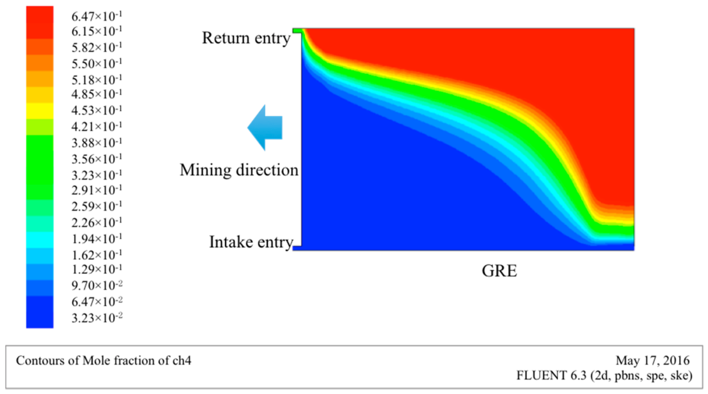
As shown in Figure 2, the gas concentration in the gob under the Y-style ventilation mode of a mining face shows that the gas concentration around the gob-side entry in the dip direction of the gob is lower than that in the return entry under the influence of the airflow in the intake entry. The gas concentration in gob is high within the range of 25 m away from the return entry. Meanwhile, with the increase of gob depth in the strike direction, the concentration of gas increases. The direction of gas concentration gradient is approximately the same as that of air leakage.
- (2)
- Contour of air pressure in the gob
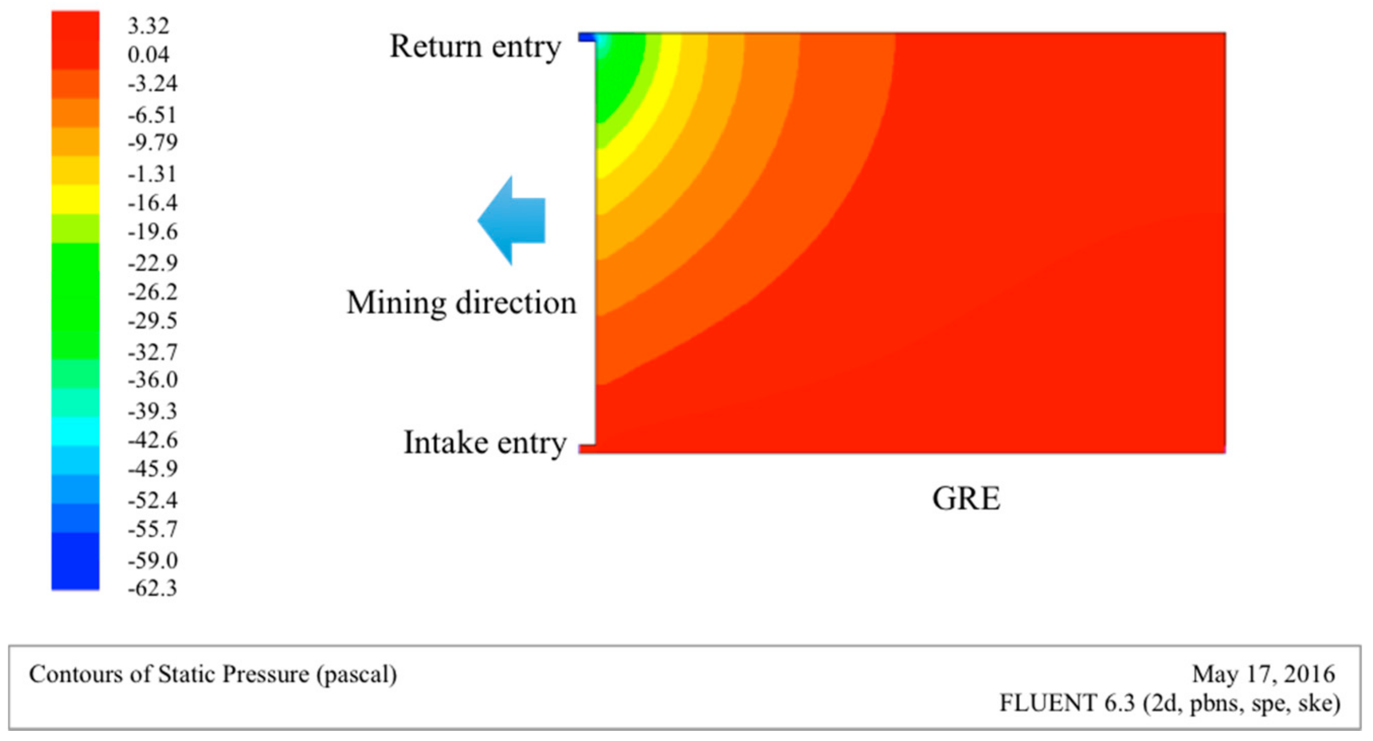
Figure 3 shows the contour of air pressure in the gob under the Y-style ventilation mode, it can be seen that the air pressure of the return entry in the T-junction is the lowest and it is the highest in the intake area of the gob-side entry. The air pressure in the gob decreases gradually along the mining direction.
2.2. Mechanical Model for GER-TCS-LR
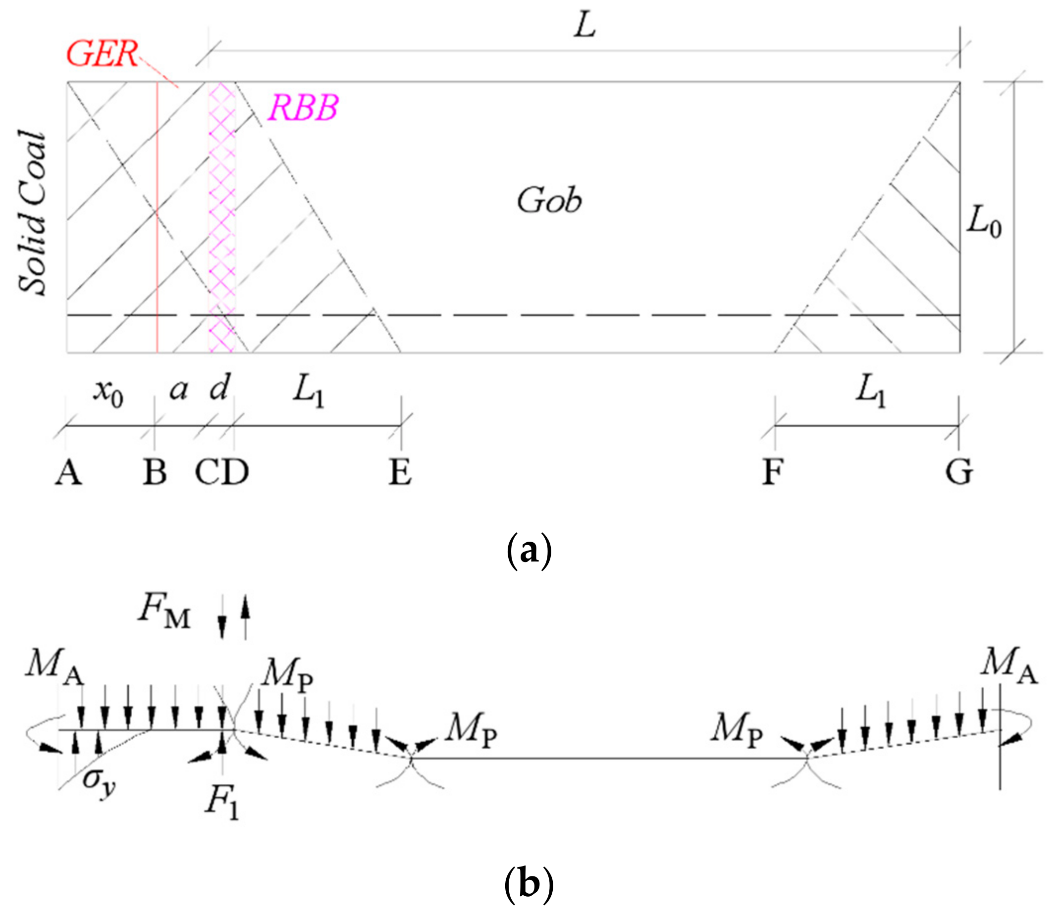
When the caved roof height is more than five times the mining height, the caved rocks can be full of gob. The caved roof at the gob edges often breaks into regular blocks that extrude and integrate mutually to form a “voussoir beam” structure. Using the method of roof load strip segmentation, a roof-cutting mechanical model of GER was proposed considering the actual size and proportion of the various rock seams [14,15], as shown in Figure 4. The mechanical model of the roof allows separation and misalignment in sedimentary rocks and applies to continuous materials and hinged rock blocks and not to loose rock mass.
The assumptions in the model are as follows: (1) the intersection of the fracture zone and the plastic zone in the solid coal is the supporting point of the roof (clamped support or simple support); (2) the immediate roof is broken on the outside of the RBB under the effect of overlying rock, the immediate roof and the RBB; (3) when the immediate roof is broken down, MP designates the ultimate bending moment of the facture point; and (4) the roof-cutting resistance of the RBB is simplified as a concentrated load. Using the block balance method, sections DE and AD (as shown in Figure 4a are derived according to Equations (1) and (2), respectively.
Using Equation (1), ; combining this with Equations (2) and (3) is derived.
where F1 is the roof-cutting resistance of the RBB, N/m; γ is the unit weight of the immediate roof, N/m3; h1 is the thickness of the immediate roof, m; a is the roadway width, m; d is the width of the RBB, m; q1 is the load of soft rocks above the immediate roof, MPa; L1 is the broken length of transverse caved blocks, which equals the periodic breakage length of roof, m; MA is the bending moment of broken immediate roof, Nm; MP is the ultimate bending moment when the immediate roof is breaking down, Nm; x0 is the width of the limited equilibrium zone, m; σy is the bearing stress of the limited equilibrium area, MPa; and x0, σy and L1 can be expressed in the following general forms [16]:
where hm is the mining height, m; A is the side abutment pressure coefficient; φ0 is the internal friction angle of the coal seam, °; C0 is the cohesion of the coal seam, MPa; k is the stress concentration factor; γ0 is the unit weight of overlying strata, N/m3; H is the mining depth, m; Pc is the support strength of solid coal, MPa; and Rt is the tensile strength of the immediate roof, MPa.
In Equation (3), the greater L1 is, the smaller F1 is, meaning there is an inversely proportional relationship between the roof-cutting resistance of the RBB and the periodic breakage length of the roof. The greater MP is, the greater F1 is, meaning the larger the resistibly flexural capacity of the roof, the larger the roof-cutting resistance needed.
When Point A is the simply supported end, MA = 0 and Equation (3) was derived. It then follows that:
Based on the characteristics of GER and the mechanical model of the immediate roof, the key parameters of GER in TCS are described below.
- (1)
- Roof-cutting resistance of the RBB
When the thickness of the immediate roof is five times the mining height or more, the caved immediate roof can be full of a gob in TCS. However, when the main roof of mudstone and the immediate roof of hard limestone compose an “upper soft and lower hard” roof structure, the immediate roof cannot actively collapse. This requires a high roof-cutting resistance of the RBB to break down the immediate roof, while the main roof of weak strata collapses passively with immediate roof caving.
- (2)
- The width of the RBB
In Equation (7), the relationship between the roof-cutting resistance of the RBB and the RBB width is positive, that is, the roof-cutting resistance of the RBB increases with increasing RBB width. In view of economy and labor intensity of GER, a slender width of RBB is preferred. Therefore, the optimal width of RBB is a key parameter of GER-RRB-TCS-LR.
Traditional roadside support can be achieved with many techniques [9,17,18,19], including the wood stack, waste rock pillar, dense hydraulic props, concrete blocks and other artificial product supports of low intensity. The supporting resistance and deformability of traditional roadside support cannot adapt for the deformation of surrounding rock and is unable to isolate gob effectively, making it difficult to achieve high mechanization. Currently, the main roadside support material is high-water material which is made of sulphoaluminate cement clinker, gypsum, lime, compound retarder, suspension agent, compound accelerator and so on [19]. The uniaxial compressive strength (UCS) test of the standard specimens (diameter 50 mm and height 100 mm) with high-water quick-setting materials under water-to-cement ratio of 1.5:1 was conducted. The material is consolidated under the test temperature of 20 °C and the initial strength is 4.48 MPa after 2 h. The strain-stress curve of the standard specimens obtained by the laboratory test system MTS815 is shown in Figure 5. Point O, A, B and C mean the initial strength, ultimate strength, post-peak strength and residual strength, respectively.
The GER takes advantage of these combined impacts, including high-water material with rapidly increasing support resistance, the high support resistance of the RBB and the overlying load, which make the limestone roof cut off along the gob-side wall and reduce the load around the GER. Therefore, a dynamic disaster caused by a roof collapse of a large area can be avoided.
3. Determination of RBB Width
3.1. Mining and Geological Conditions of the Tested Roadway
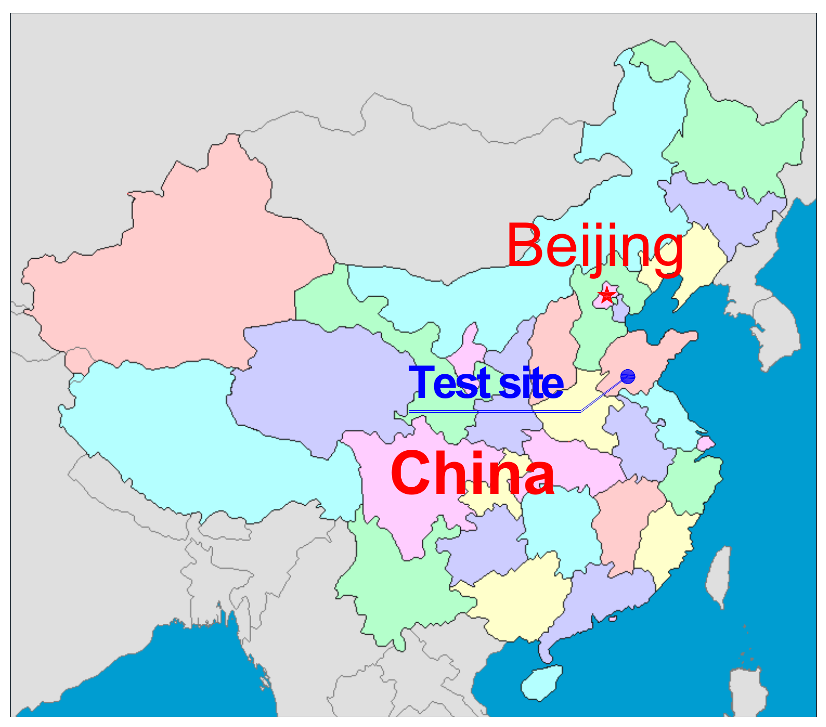
The Nantun coal mine, which is located in the Yanzhou mining area of Shandong Province, eastern China (Figure 6), was selected for the case study. Panel 3602 in the Nantun coal mine mainly mines the No. 16-1 coal seam, buried at a depth of 575 m. The average thickness of the coal seam is 0.9 m, with an average inclination of 4°. The panel employs fully mechanized mining technology with a panel width of 164.5 m. The roof and floor lithology of panel 3602 is shown in Table 1.
Rock mechanics tests and field observations of panel 3602 showed that for the high strength limestone roof, roof caving occurs suddenly when subjected to a small deformation. The main roof and immediate roof of panel 3602 are mudstone and limestone, respectively, that is, the typical “upper soft and lower hard” stratum, passively caved limestone roof. Therefore, the construction of the GER requires higher roof-cutting resistance or other measures to make the gob roof cave immediately with coal mining, to prevent a dynamic disaster or strong dynamic load to the surrounding rock of the GER.
3.2. Determination of the Roof-Cutting Resistance of the RBB
In accordance with the mining and geological conditions of panel 3602, where m = 0.9 m, A = 0.8, φ0 = 21°, C0 =1.4 MPa, k = 3.0, γ0 = 2.5 × 10⁴ N/m3, H = 420 m, Pc = 0.1 MPa, γ = 2.7 × 10⁴ N/m3, h1 = 5.0 m, q1 = 0.5 MPa and Rt = 6.23 MPa, using the math software Mathcad, the above data were put into Equations (4) and (6) to give x0 = 2.1 m and L1 = 10.2 m.
The ratio of roof-cutting resistance of the RBB and the width of the RBB is defined as the RBB supporting strength, as described by Equation (8):
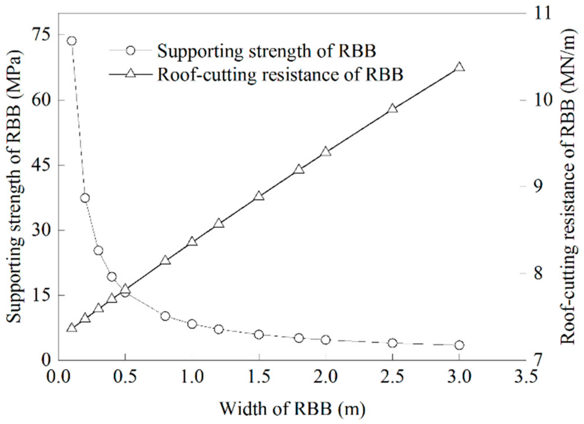
When the average roadway width is 3.4 m, the relationship between the width of the RBB and the roof-cutting resistance of the RBB and supporting strength can be obtained from Equations (7) and (8), as shown in Figure 7.
From Figure 7, the relationship between the supporting strength of the RBB and the width of the RBB can be derived as a composite curve: , variance is 0.978.
The derived curve of the supporting strength of the RBB and the RBB width shows that the required supporting strength of the RBB increases rapidly as the width of the RBB decreases, when the RBB width is between 0.1 m and 1.1 m. Otherwise, the required support strength of the RBB decreases slowly. Considering the cost and mechanical properties of the RBB, the width of the RBB should be greater than 1.1 m, while the roof-cutting resistance of the RBB should be greater than 8.465 MN/m and the supporting strength of the RBB should not be less than 7.696 MPa.
Using an example of an RBB with high-water, fast-setting material and considering a given safety coefficient k0, the width of the RBB is d, the required supporting strength of the RBB is σF and the uniaxial compressive strength (UCS) of the high-water material (7 d age) is σ0. Then:
If k0 is defined as 1.2, the UCS of the high-water material (7 d age) is required to be greater than 9.24 MPa. When the water-to-cement ratio of high-water material is 1.5:1, its UCS is 10 MPa after 7 days [19], meeting the requirements of the RBB supporting strength.
The analytical results show that the roof-cutting resistance of the RBB should not be less than 8.465 MN/m when the width of the RBB is greater than 1.1 m and the water-to-cement ratio of the high-water material is 1.5:1.
3.3. Determination of the RBB Width
To determine an appropriate width of the RBB, a numerical simulation was used to analyze the vertical stress and the surrounding rock deformation of the GER with respect to different widths of RBB. Results of the numerical model were combined with the result of the theoretical calculations to determine the width of the RBB.
3.3.1. Numerical Model
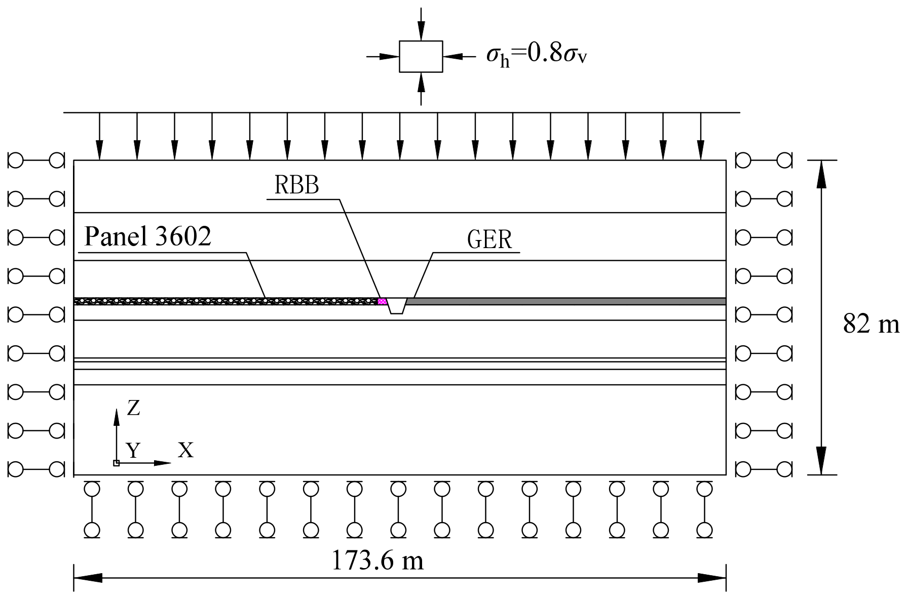
Based on the mining and geological conditions of Panel 3602 in the Nantun coal mine, FLAC3D [20] was used to construct a numerical model of plan-strain conditions, as shown in Figure 8. The model dimensions were 173.6 m × 200 m × 82 m, with one-half of panels 3604 and 3602 and the roadway system between them. At the top of the models, a vertical load was applied to simulate the overburden weight. The at-rest pressure coefficients along the x and y directions were both taken as 0.8 according to the in situ stresses of the No. 16-1 coal seam. The horizontal and bottom sides were roller constrained. The Mohr–Coulomb criterion was used to simulate the rock strata and the Cvisc creep model was used for the RBB of the GER.
Based on the laboratory results of the mechanical properties of rock and coal samples, the parameters employed in the model have been determined that elastic modulus, cohesion and tensile strength is 0.2 of the laboratory testing results and the Poisson ratio is 1.2 of the laboratory testing results, following the primary works of Perry [21] and Mohammad [22]. In addition, few trial model tests have been carried out and the mechanical parameters were adjusted in reference to the in situ measurement of the displacement and the width of yield zones developed around the roadways [23]. The final rock strata property parameters in the numerical model are shown in Table 2 and Table 3. The modeling process was as follows: (i) calculation of the initial state induced by gravity; (ii) modeling the excavations of the headgate in panel 3602; (iii) retreating panel 3602; and (iv) modeling the retaining of the headgate in panel 3602 with respect to different RBB widths (0.8 m, 1.2 m, 1.6 m and 2.0 m).
3.3.2. Results and Discussion
- (1)
- Convergence of GER with respect to RBB width
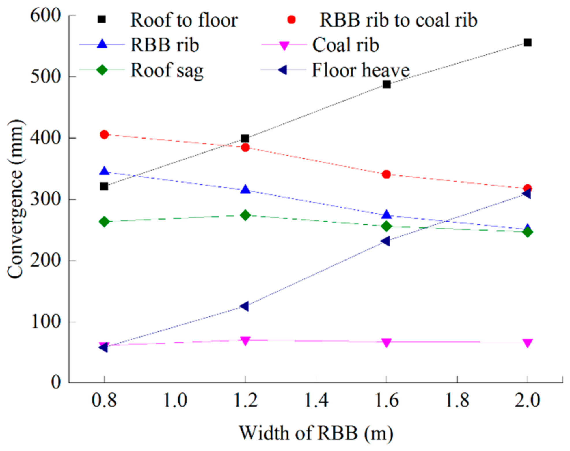
The RBB width plays an important role in the convergence of surrounding rock in the GER, as shown in Figure 9. The roof-cutting effect of the RBB becomes stronger as the RBB width increases. When the width of the RBB is greater than 1.6 m, the roof subsidence changes little and the roof-cutting effect is weakened.
The floor heave of GER increases with increasing RBB width. When the width of the RBB increased from 0.8 m to 1.2 m, the floor heave increased two-fold to 146.2 mm, representing an increase of 68.3%.
The RBB convergence gradually decreases with the increasing width of the RBB. When the width of the RBB increased from 1.2 m to 1.6 m, the convergence of the RBB decreased from 281.1 mm to 237.7 mm, representing the convergence reduction of 15.4%. When the width of the RBB increased from 1.6 m to 2.0 m, the convergence of the RBB decreased 16.8 mm, a reduction of 15.4%.
- (2)
- Stress distribution around the GER with respect to RBB width
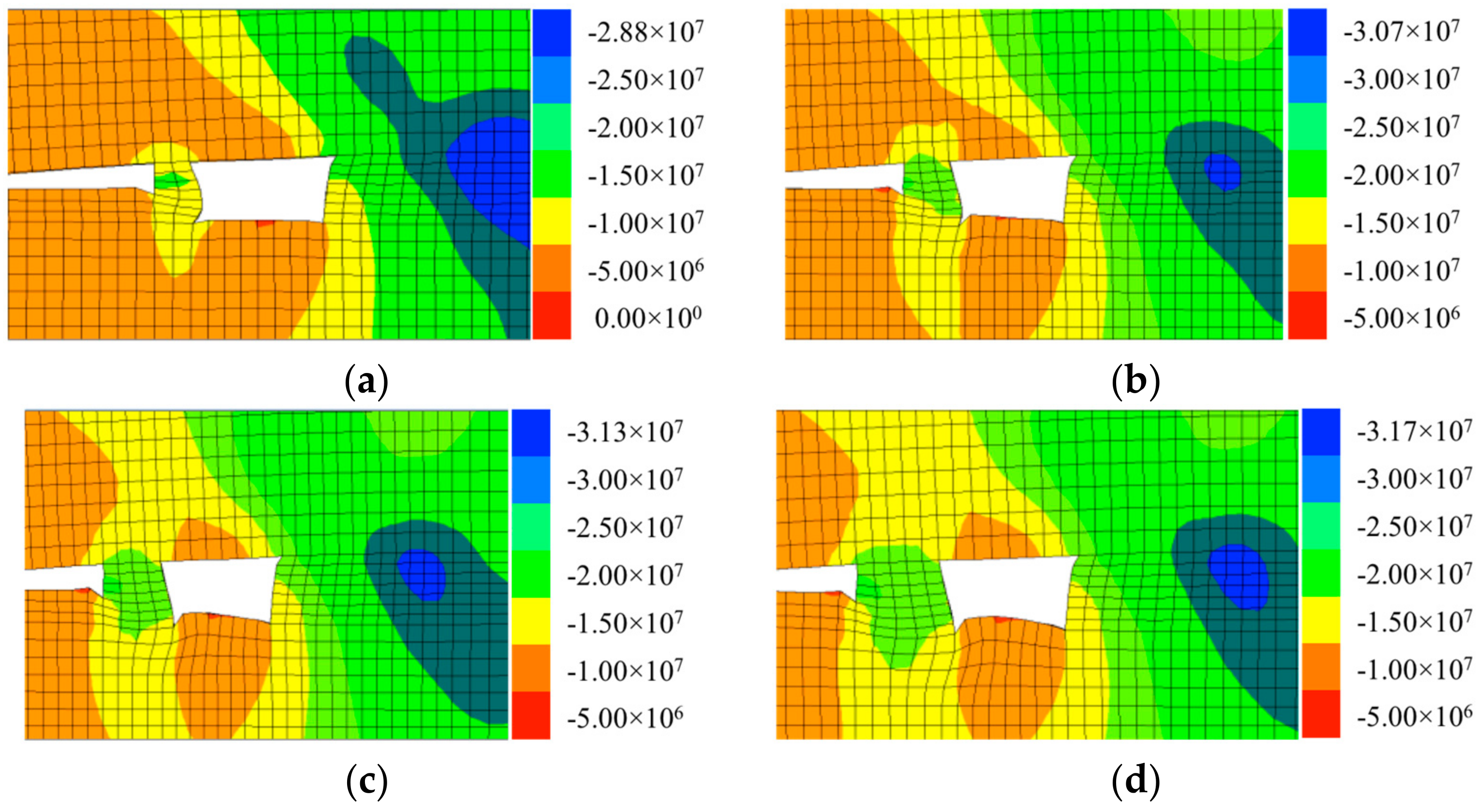
Vertical stress distributions around the GER with respect to the different widths of RBB are shown in Figure 10.
The results show that the vertical stress of the RBB gradually increases and the bearing capacity of the RBB becomes stronger with increasing RBB width. When the width of the RBB increased from 0.8 m to 1.2 m, the vertical stress of the RBB increased from 10.715 MPa to 13.25 MPa, an increase of 23.7%. When the width of the RBB increased to 1.6 m, the vertical stress of the RBB increased 6.8% to 14.15 MPa, representing a relatively small increase. When the width of the RBB increased to 2.0 m, the vertical stress of the RBB remained stable.
With increasing RBB width, the vertical stress in the coal rib wall increases gradually and the peak stress is approximately 3.5–4.0 m away from the roadside. When the width of the RBB increased from 0.8 m to 1.2 m, the vertical stress of the coal rib wall increased from 28.86 MPa to 30.67 MPa, an increase of 6.3%. When the width of RBB was subsequently increased to 1.6 m, the vertical stress of the coal rib wall increased 2.1% to 31.3 MPa. When the RBB width increased to 2.0 m, the vertical stress in the solid coal rib wall remained stable.
Therefore, a headgate of panel 3602 is retained with the RBB width of 1.2 m; this could decrease the GER convergence and reduce RBB construction costs.
4. Field Test and Field Monitoring
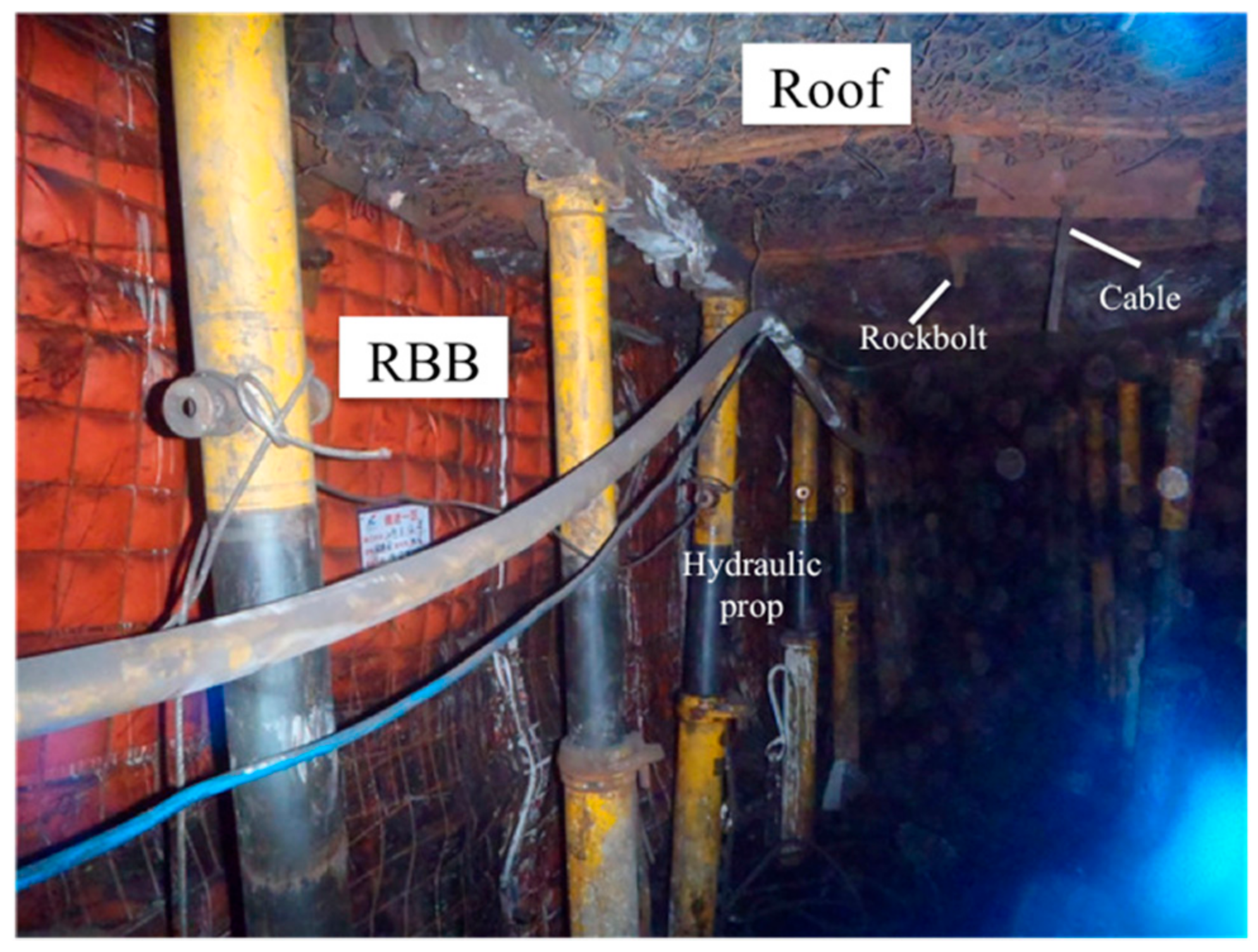
According to the above analysis, the RBB is 1.2 m wide, 0.9 m high and has a 1.33 width-height ratio. High-water, fast-setting material with a water-cement ratio 1.5:1 was used to construct the RBB. Figure 11 shows the GER effect. In the 100 m ranges behind the working face, hydraulic props and a steel beam are used to temporarily support the roof of RBB. The roof in the gob nearby the GRE will collapse under the effect of RBB.
During construction of the GER of panel 3602, two monitoring stations were installed in the GER to record the convergence and RBB loading. The results in Figure 12 show that GER convergence behind the working face can be divided into three stages under the hard roof condition in a TCS (Stages I, II, III):
Stage I—in the range of 30 m behind the working face, the gob roof continuously subsides and the surrounding rock deformation increases after the RBB is constructed; in the area of 30 m behind the working face, the limestone roof of the GER in the gob side is cut off under the action of complicated forces, where the convergence almost accounts for the one-third of total convergence, and the convergence rate of surrounding rock reaches the maximum at this time.
Stage II—in the range from 30 to 110 m behind the working face, the convergence rate of surrounding rock gradually decreases. After the limestone roof collapses, the bearing structure composed of the coal seam support, caved rocks and RBB undertakes the load from the overlying rock, caved rocks compact the gob, and the surrounding rock deformation gradually increases as the convergence rate of the surrounding rock slows down.
Stage III—at a distance of 110 m behind the working face, the surrounding rock deformation of GER tends to be stable; the roof to floor convergence and RBB rib to coal rib convergence of the RBB are approximately 353 mm and 297 mm, respectively. The roof-to-floor convergence is always more than that of rib-to-rib in the mining period. It showed that the parameters of rock properties and RBB in the simulations were reasonable and reliable. Considering the requirement of GER cross-sections for ventilation, the section of the GRE in the mining period could meet the requirement. Field measurement results indicated that RBB width and roof-cutting resistance in the field were rational.
5. Conclusions
In accordance with the caving style of a limestone roof, using the Y-style ventilation mode, the air pressure of the return roadway in the T-junction is the lowest and it is the highest in the air inlet area of the gob-side entry. The gas concentration around the gob-side entry in the dip direction of the gob is mitigated.
The mechanics model of the GER roof and the RBB indicate that the hard roof collapsed passively under the interaction of the RBB and the overlying rock strata; the roof-cutting resistance of the RBB and its width play a key role in GER with limestone roof in a TCS. A roof-cutting mechanical model of GER with a roadside backfill body (RBB) was proposed to determine the roof-cutting resistance and the width of the RBB.
Based on the mechanical model, analytical results show that the greater the RBB width, the greater its roof-cutting resistance. Fitting algebraic relationships between the RBB’s roof-cutting resistance and its width can determine an optimal roof-cutting resistance. The floor heave of GER increases with increasing RBB width. When the width of the RBB increased from 0.8 m to 1.2 m, the floor heave increased two-fold to 146.2 mm. Using numerical simulation to study the stress distributions and the deformation of GER with respect to RBB width, an appropriate RBB width can be determined.
Based on the geological conditions of panel 3602 in a TCS with a limestone roof, the roof-cutting resistance of the RBB was determined as 8.465 MN/m, and the width of the RBB and the water-to-cement ratio of high-water material were 1.2 m and 1.5:1, respectively. Field measurement indicated that these research results were successfully applied in engineering practice.
It is noted that this model was only tested on a TCS. Further study is necessary for medium-thick or thick seams. In addition, further research efforts to improve the high-water material are required to popularize the GER technique.
Author Contributions
S.Y. conceived the research and wrote the paper, T.L. analyzed the data and contributed numerical simulation. J.B. directed the paper structure. W.W. participated in collecting the data and language editing. All authors have read and approved the final manuscript.
Acknowledgments
This research was financially supported by the Fundamental Research Funds for the Central Universities (2014QNB29), National Natural Science Foundation of China (51604268 and 51574227), Independent Research Project of State Key Laboratory of Coal Resources and Safe Mining, CUMT (SKLCRSM18X08), and PAPD (SZBF2011-6-B35). Also, the authors are thankful to Davide Elmo and anonymous reviewers for their comments and suggestions.
Conflicts of Interest
The authors declare no conflict of interest.
References
- Wang, D. Study on Integrated Assessment and Regulation Policies of Coal Production Capacity in China; China University of Mining and Technology Press: Xuzhou, China, 2013; pp. 12–16. [Google Scholar]
- Huang, N.; Jiang, Y.; Li, B.; Liu, R. A numerical method for simulating fluid flow through 3-D fracture networks. J. Nat. Gas Sci. Eng. 2016, 33, 1271–1281. [Google Scholar] [CrossRef]
- Deng, Y.; Wang, S. Feasibility analysis of gob-side entry retaining on a working face in a steep coal seam. Int. J. Min. Sci. Technol. 2014, 24, 499–503. [Google Scholar] [CrossRef]
- Yang, H.; Cao, S.; Li, Y.; Sun, C.; Guo, P. Soft Roof Failure Mechanism and Supporting Method for Gob-Side Entry Retaining. Minerals 2015, 5, 707–722. [Google Scholar] [CrossRef]
- Zhang, Z.Y.; Hideki, S.; Qian, D.Y.; Takashi, S. Application of the retained gob-side gateroad in a deep underground coalmine. Int. J. Min. Reclam. Environ. 2016, 30, 371–389. [Google Scholar] [CrossRef]
- Lu, S. Strata Behaviors of Entry without Chain Pillar; China Coal Industry Press: Beijing, China, 1982; pp. 1–2. [Google Scholar]
- Tan, Y.L.; Yu, F.H.; Ning, J.G.; Zhao, T.B. Design and construction of entry retaining wall along a gob side under hard roof stratum. Int. J. Rock Mech. Min. Sci. 2015, 77, 115–121. [Google Scholar] [CrossRef]
- Huang, Y.L.; Li, J.M.; Song, T.Q.; Kong, G.Q.; Li, M. Analysis on Filling Ratio and Shield Supporting Pressure for Overburden Movement Control in Coal Mining with Compacted Backfilling. Energies 2017, 10, 31. [Google Scholar] [CrossRef]
- Jiang, H.; Miao, X.; Zhang, J.; Liu, S. Gateside packwall design in solid backfill mining-A case study. Int. J. Min. Sci. Technol. 2016, 26, 261–265. [Google Scholar] [CrossRef]
- Hidalgo, K.P.; Nordlund, E. Failure process analysis of spalling failure-Comparison of laboratory test and numerical modelling data. Tunn. Undergr. Space Technol. 2012, 32, 66–77. [Google Scholar] [CrossRef]
- Villaescusa, E.; Varden, R.; Hassell, R. Quantifying the performance of resin anchored rock bolts in the Australian underground hard rock mining industry. Int. J. Rock Mech. Min. Sci. 2008, 45, 94–102. [Google Scholar] [CrossRef]
- Sun, X.M.; Liu, X.; Liang, G.F.; Wang, D.; Jiang, Y.L. Key parameters of gob-side entry retaining formed by roof cut and pressure releasing in thin coal seams. China J. Rock Mech. Eng. 2014, 33, 1449–1456. (In Chinese) [Google Scholar]
- Liu, R.; Jiang, Y.; Li, B.; Yu, L. Estimating permeability of porous media based on modified Hagen–Poiseuille flow in tortuous capillaries with variable lengths. Microfluid. Nanofluid. 2016, 20, 120. [Google Scholar] [CrossRef]
- Chen, Y.; Bai, J.B.; Zhu, T.L.; Yan, S.; Zhao, S.H.; Li, X.C. Mechanisms of roadside support in gob-side entry retaining and its application. Rock Soil Mech. 2012, 32, 1427–1432. [Google Scholar]
- Guo, Z.; Mou, W.; Huang, W.; Duan, H. Analysis on roadside support method with constant resistance yielding-supporting along the goaf under hard rocks. Geotech. Geol. Eng. 2016, 34, 827–834. [Google Scholar] [CrossRef]
- Hou, C.J.; Ma, N.J. Stress in in-seam roadway sides and limit equilibrium zone. J. China Coal Soc. 1989, 4, 21–29. [Google Scholar]
- Yang, D.W.; Ma, Z.G.; Qi, F.Z.; Gong, P.; Liu, D.P.; Zhao, G.Z.; Zhang, R.R. Optimization study on roof break direction of gob-side entry retaining by roof break and filling in thick-layer soft rock layer. Geomech. Eng. Int. J. 2017, 13, 195–215. [Google Scholar]
- Zhang, Y.; Tang, J.; Xiao, D.; Sun, L.; Zhang, W. Spontaneous caving and gob-side entry retaining of thin seam with large inclined angle. Int. J. Min. Sci. Technol. 2014, 24, 441–445. [Google Scholar] [CrossRef]
- Zhang, Z.Z.; Bai, J.B.; Chen, Y.; Yan, S. An innovative approach for gob-side entry retaining in highly gassy fully-mechanized longwall top-coal caving. Int. J. Rock Mech. Min. Sci. 2015, 80, 1–11. [Google Scholar] [CrossRef]
- Itasca Consulting Group. FLAC3D Instruction Manual; Itasca Consulting Group: Minneapolis, MN, USA, 2007. [Google Scholar]
- Perry, K.A.; Unrug, K.F.; Harris, K.W.; Raffaldi, M.J. Influence of roof/floor interface on coal pillar performance. In Proceedings of the 32th International Conference on Ground Control in Mining, Morgantown, WV, USA, 30 July–1 August 2012. [Google Scholar]
- Mohammad, N.; Reddish, D.J.; Stace, L.R. The relation between in situ and laboratory rock properties used in numerical modelling. Int. J. Rock Mech. Min. Sci. 1997, 34, 289–297. [Google Scholar] [CrossRef]
- Zhang, G.C.; Liang, S.J.; Tan, Y.L.; Xie, F.X. Numerical modeling for longwall pillar design: A case study from a typical longwall panel in China. J. Geophys. 2018, 15, 121–134. [Google Scholar] [CrossRef]
Figure 1.
Schematic diagram of Gob-side entry retaining-thin coal seam-limestone roof (GER-TCS-LR): (a) Plan view; (b) I-I section and (c) II-II section.
Figure 1.
Schematic diagram of Gob-side entry retaining-thin coal seam-limestone roof (GER-TCS-LR): (a) Plan view; (b) I-I section and (c) II-II section.
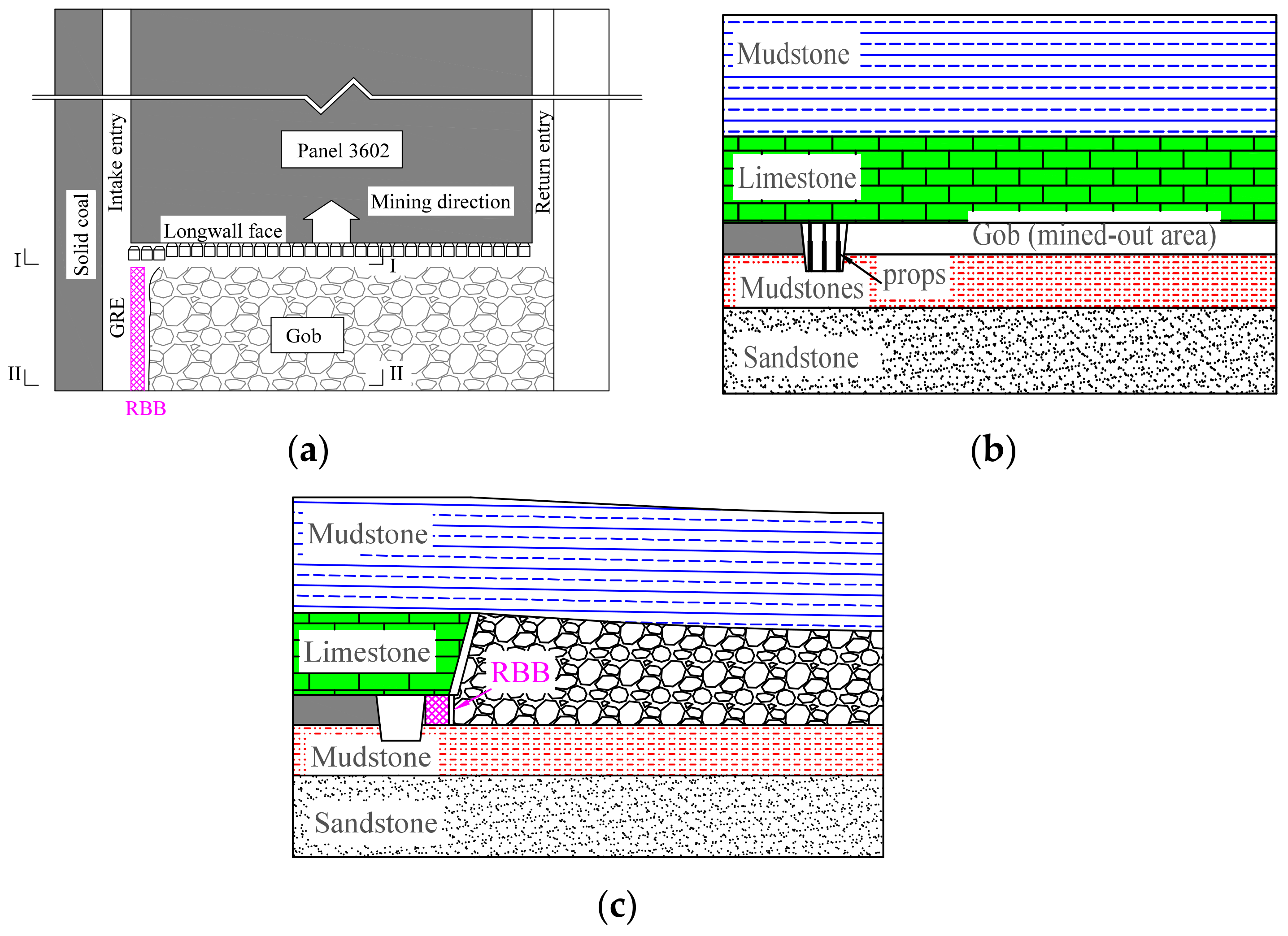
Figure 2.
Contour of gas concentration in the gob of GER-TCS-LR.

Figure 3.
Contour of air pressure in the gob of GER-TCS-LR.

Figure 4.
Roof-cutting mechanical model of GER: (a) Plan view: supported by three edges (periodic weighting) and (b) Section view: loading state of caved roof.
Figure 4.
Roof-cutting mechanical model of GER: (a) Plan view: supported by three edges (periodic weighting) and (b) Section view: loading state of caved roof.

Figure 5.
The stress-strain curve of the high-water material in the laboratory.
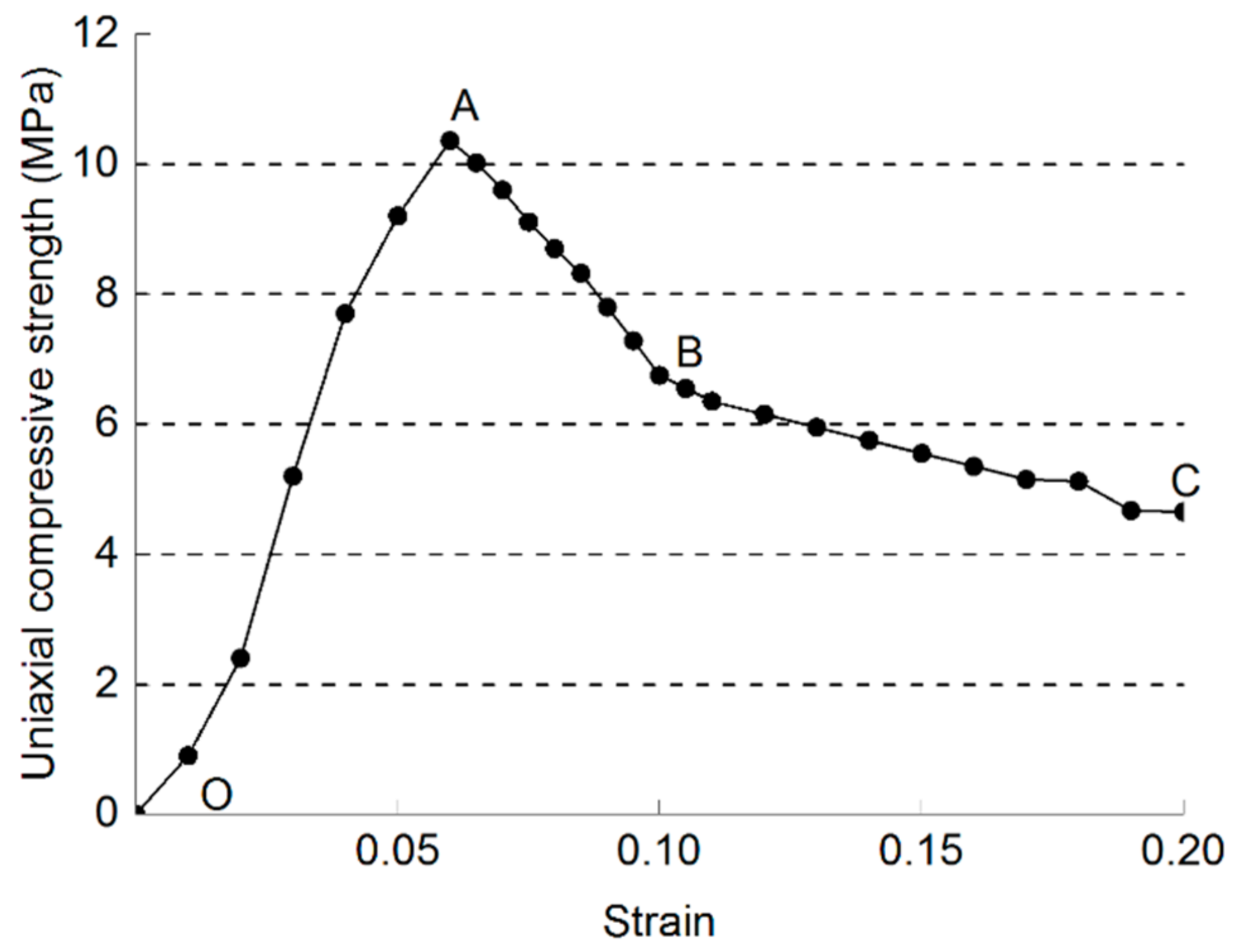
Figure 6.
Location of the test site.

Figure 7.
Roof-cutting resistance and support strength of the roadside backfill body (RBB) with respect to RBB width.
Figure 7.
Roof-cutting resistance and support strength of the roadside backfill body (RBB) with respect to RBB width.

Figure 8.
Numerical simulation model.

Figure 9.
GER convergence with respect to the width of RBB.

Figure 10.
Vertical stress distribution with respect to RBB width (units: Pa): (a) RBB of 0.8 m wide; (b) RBB of 1.2 m wide; (c) RBB of 1.6 m wide; and (d) RBB of 2.0 m wide.
Figure 10.
Vertical stress distribution with respect to RBB width (units: Pa): (a) RBB of 0.8 m wide; (b) RBB of 1.2 m wide; (c) RBB of 1.6 m wide; and (d) RBB of 2.0 m wide.

Figure 11.
GER effect.

Figure 12.
Convergence of GER-LR-TCS.


Table 1.
Roof and floor lithology of panel 3602.
| Name | Lithology | Thickness (m) | Lithological Description |
|---|---|---|---|
| Main roof | Mudstone | 6.4 | Light grey, with mudstone and siltstone stripe |
| Immediate roof | Limestone | 5.0 | Dense hard, rich fracture |
| Coal bed | Coal | 0.9 | |
| Immediate floor | Aluminous mudstones | 2.1 | Light grey, water expand |
| Main floor | Sandstone | 5.0 | Grey with horizontal bedding |
Table 2.
Rock mechanical properties used in the numerical model.
| Rock Strata | Thickness (m) | Denstity (kg/m3) | Bulk Modulus (GPa) | Shear Modulus (GPa) | Cohesion (MPa) | Friction Angle (°) |
|---|---|---|---|---|---|---|
| Underlying strata | 12 | 2500 | 10.0 | 7.6 | 5.2 | 41 |
| Siltstone | 2.1 | 2550 | 8.8 | 6.3 | 4.0 | 38 |
| Aluminum mudstone | 1 | 1800 | 5.2 | 4.0 | 2.5 | 25 |
| No. 16-2 coal seam | 0.5 | 1400 | 4.3 | 2.7 | 1.6 | 23 |
| Sandstone | 5 | 2650 | 3.5 | 2.1 | 1.0 | 17 |
| Aluminum mudstone | 2.1 | 1700 | 4.2 | 2.4 | 2.2 | 25 |
| No. 16-1 coal seam | 0.9 | 1400 | 3.0 | 1.5 | 1.4 | 21 |
| Limestone | 5 | 2900 | 9.7 | 7.1 | 5.2 | 36 |
| Mudstone | 6.4 | 1800 | 4.3 | 2.2 | 1.5 | 28 |
| Overlying strata | 17 | 2500 | 8.9 | 6.2 | 3.2 | 32 |
Table 3.
Mechanical parameters of RBB.
| Properties | Values | Properties | Values |
|---|---|---|---|
| Bulk modulus (GPa) | 2.9 | K shear (GPa) | 1.6 |
| Shear modulus (GPa) | 1.3 | Kviscosity (GPa) | 3.0 |
| Cohesion (MPa) | 3.2 | Mshear (GPa) | 2.2 |
| Internal friction angle (°) | 32 | Mviscosity (GPa) | 2.4 |
© 2018 by the authors. Licensee MDPI, Basel, Switzerland. This article is an open access article distributed under the terms and conditions of the Creative Commons Attribution (CC BY) license (http://creativecommons.org/licenses/by/4.0/).
Share and Cite
MDPI and ACS Style
Yan, S.; Liu, T.; Bai, J.; Wu, W. Key Parameters of Gob-Side Entry Retaining in A Gassy and Thin Coal Seam with Hard Roof. Processes 2018, 6, 51. https://doi.org/10.3390/pr6050051
AMA Style
Yan S, Liu T, Bai J, Wu W. Key Parameters of Gob-Side Entry Retaining in A Gassy and Thin Coal Seam with Hard Roof. Processes. 2018; 6(5):51. https://doi.org/10.3390/pr6050051
Chicago/Turabian StyleYan, Shuai, Tianxiao Liu, Jianbiao Bai, and Wenda Wu. 2018. "Key Parameters of Gob-Side Entry Retaining in A Gassy and Thin Coal Seam with Hard Roof" Processes 6, no. 5: 51. https://doi.org/10.3390/pr6050051
Note that from the first issue of 2016, this journal uses article numbers instead of page numbers. See further details here.