1. Introduction
The evolution of mobile applications and devices, such as the always-connected smart mobiles, is stimulating the always-growing demand for broadband wireless services. This entails a substantial increase in the wireless networks traffic, which can be supported only by improving the current networks capacity. A reduction of the cells dimension, together with the implementation of new high-speed wireless communication standards, such as Long Term Evolution-Advanced (LTE-A) [
1], is a possible temporary solution.
Today’s mobile communications are confined into the Ultra-High Frequencies (UHF) band, laying in the 300 MHz–3 GHz frequency range, whereas the millimeter-wave band (MMB), which is a portion of the radiofrequency (RF) spectrum ranging from 3 GHz to 300 GHz, is at present underutilized. In this scenario, the MMB reveals a suitable solution for next generation wireless communications, since the availability of very large bandwidths in that frequency range allows us to accommodate a huge amount of data traffic, thus enabling the transmission of Ultra-Wide Band (UWB) signals [
2]. Nowadays, the main issues that hamper the utilization of the MMB are related to technical limitations of the electronic equipments. Indeed, atmospheric attenuation is not a problem, since it keeps lower than 0.05 dB/km up to 350 GHz, except for the narrow high absorption frequency regions due to oxygen and water vapor [
3] which can, even so, be exploited for short-range applications. On the other hand, the design and realization of highly stable RF oscillators and low-noise mixers, able to work beyond the UHF band, is a very hard task and, moreover, today’s base stations are not able to treat simultaneously signals ranging from few hundreds of MHz to tens of GHz.
The generation of ultra-stable RF signals from UHF to MMB is made possible by resorting to photonic technologies [
4]. The heterodyning of modes of a MLL generates a frequency comb of phase-locked RF oscillations that can be employed as carrier signals over different frequency bands. The timing jitter of a MLL reaches values as low as a few fs and, since the phase noise power spectral density of the
N-th mode in the electrical spectrum of a MLL scales as
N2, all the generated carriers are affected by the same low timing jitter [
5]. Moreover, as recently demonstrated, optical sampling, possibly made by exploiting the same MLL, can be conveniently exploited as photonic down-converter [
6] or up-converter [
7,
8], thus allowing an effective conversion over frequency spans of tens of GHz. As a consequence of the use of photonic-based techniques, the possible availability of a single transceiver able to manage multiple frequency UWB signals, would reasonably reduce the hardware requirements, paving the way for the implementation of future flexible, multi-band and multi-protocol base stations.
In this paper, we present and characterize an up- and down-converter, suitable as core structure of a photonics-based RF transceiver, able to either up-convert or down-convert UWB signals over different frequency bands. The system’s performance has been evaluated by EVM measurement, demonstrating a negligible power penalty. The presented transceiver does not suffer from inter-channel cross-talk or channel self-interference, and does not need complex equalization schemes or signal post-processing.
The presented architecture is compact in size, and since the photonic integration of Electro-optical modulators and MLLs is nowadays possible, a whole system integration can be considered as a viable solution for the development of a single multi-band transceiver, suitable for base stations as well as for portable devices [
9].
2. Principle of Operation and Experimental Setup
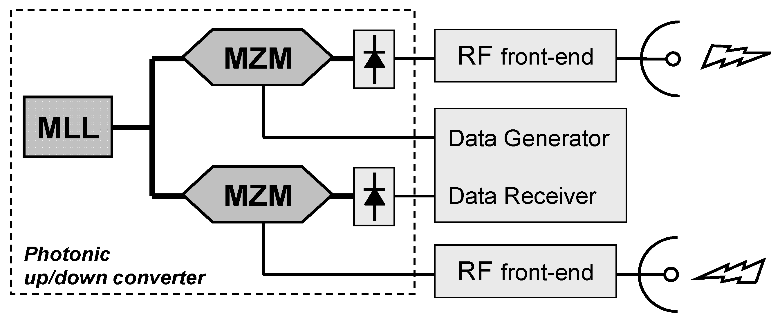
Figure 1 shows the scheme of principle of the transceiver. The basic structure is composed of a MLL cascaded by a Mach-Zehnder modulator (MZM) and a photodiode. The structure, replicated twice, allows us to obtain both a transmitter and a receiver in the same module, thus sharing the same MLL.
Figure 1.
Scheme of principle of the transceiver. MLL: Mode-locked laser; MZM: Mach-Zehnder modulator.
Figure 1.
Scheme of principle of the transceiver. MLL: Mode-locked laser; MZM: Mach-Zehnder modulator.
A modulation signal at frequency fs is applied to the output of a MLL by means of the MZM, thus generating an optically sampled double-sideband (DSB) modulated signal. The signal spectrum is then replicated, as upper- and lower-side bands (USB and LSB, respectively), around every line in the MLL spectrum. When this comb of optical channels is fed into the photodiode, the heterodyning of all the spectral components produces an electrical spectrum in which the signal is replicated every fs + Nƒrep, as an USB, and every fs − Nƒrep, as a LSB, where ƒrep is the MLL repetition frequency, and N is a non-negative integer. In this way, a signal generated at a low intermediate frequency (IF) is up-converted at a carrier frequency equal to IF + Nƒrep to be transmitted, even in multiple frequency bands, while a signal received at that frequency (IF + Nƒrep) is down-converted back to its respective IF frequency. An electronic front-end between the photonic up- and down-converters and the antennas provide the necessary electrical filtering and amplification.
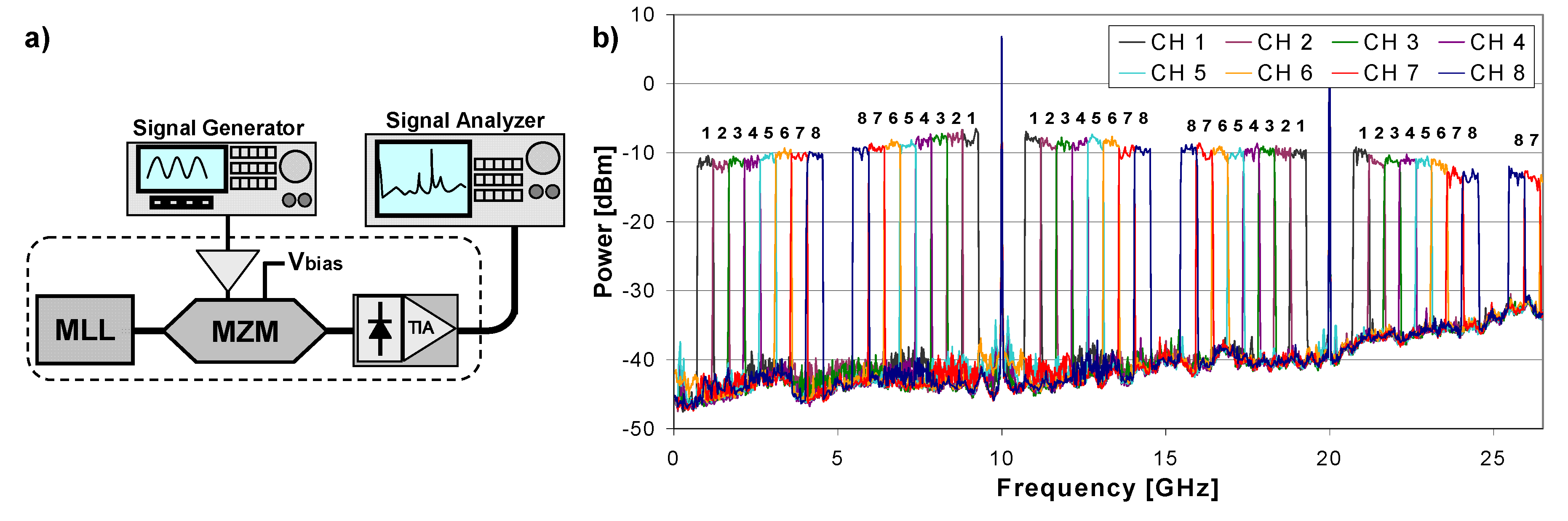
In the experimental activity a 10 GHz-repetition rate MLL, with 5 dBm average output power, together with a 40 GHz MZM, driven by 5 dBm RF input power, and a 40 GHz linear photoreceiver, cascaded by a trans-impedance amplifier (TIA), are employed. An Agilent PSG-E8267D vector signal generator (VSG) is used to generate the RF UWB signals around the IF, that is then received by a 26.5 GHz bandwidth Vector Signal Analyzer (VSA) Agilent MXA-N9060A, as shown in
Figure 2a.
According to the 802.11 g standard, each sub-channel consists of 52 64-QAM modulated OFDM sub-carriers, carrying 54 Mbps and thus occupying 22 MHz bandwidth. Then, 22 of these sub-channels are combined to obtain a single UWB channel with a bandwidth of 484 MHz and a data rate of about 1.2 Gbps. In the experiment, eight adjacent UWB channels are generated, and their IFs are chosen between DC and 5 GHz, which is half of the MLL repetition frequency ƒrep, thus avoiding spectral overlapping. In more detail, the channels are equally spaced and centered at 0.9 GHz, 1.38 GHz, 1.87 GHz, 2.35 GHz, 2.84 GHz, 3.32 GHz, 3.81 GHz, and 4.29 GHz, respectively.
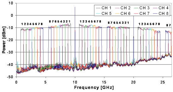
The produced electrical spectrum is depicted in
Figure 2b. The UWB RF signal spectra, generated by the VSG around IF, are numbered in order of increasing IF and shown between DC and 5 GHz. Each DSB channel is replicated around every harmonic of the MLL, and it is symmetrically spaced by IF from the respective MLL line. The first two harmonics of the MLL are depicted at 10 GHz and 20 GHz, and the groups of eight adjacent 484 MHz-wide channels are clearly visible as well.
Figure 2.
(a) Experimental setup. TIA: Trans-impedance amplifier; (b) Electrical spectrum of the transmitted signal. The channels are numbered in order of increasing IF.
Figure 2.
(a) Experimental setup. TIA: Trans-impedance amplifier; (b) Electrical spectrum of the transmitted signal. The channels are numbered in order of increasing IF.
3. Experimental Results
The performance of the presented system has been evaluated by measuring the EVM of the central 22 MHz sub-channel of every up-converted and down-converted 484 MHz channel, by receiving the converted signals with the VSA.
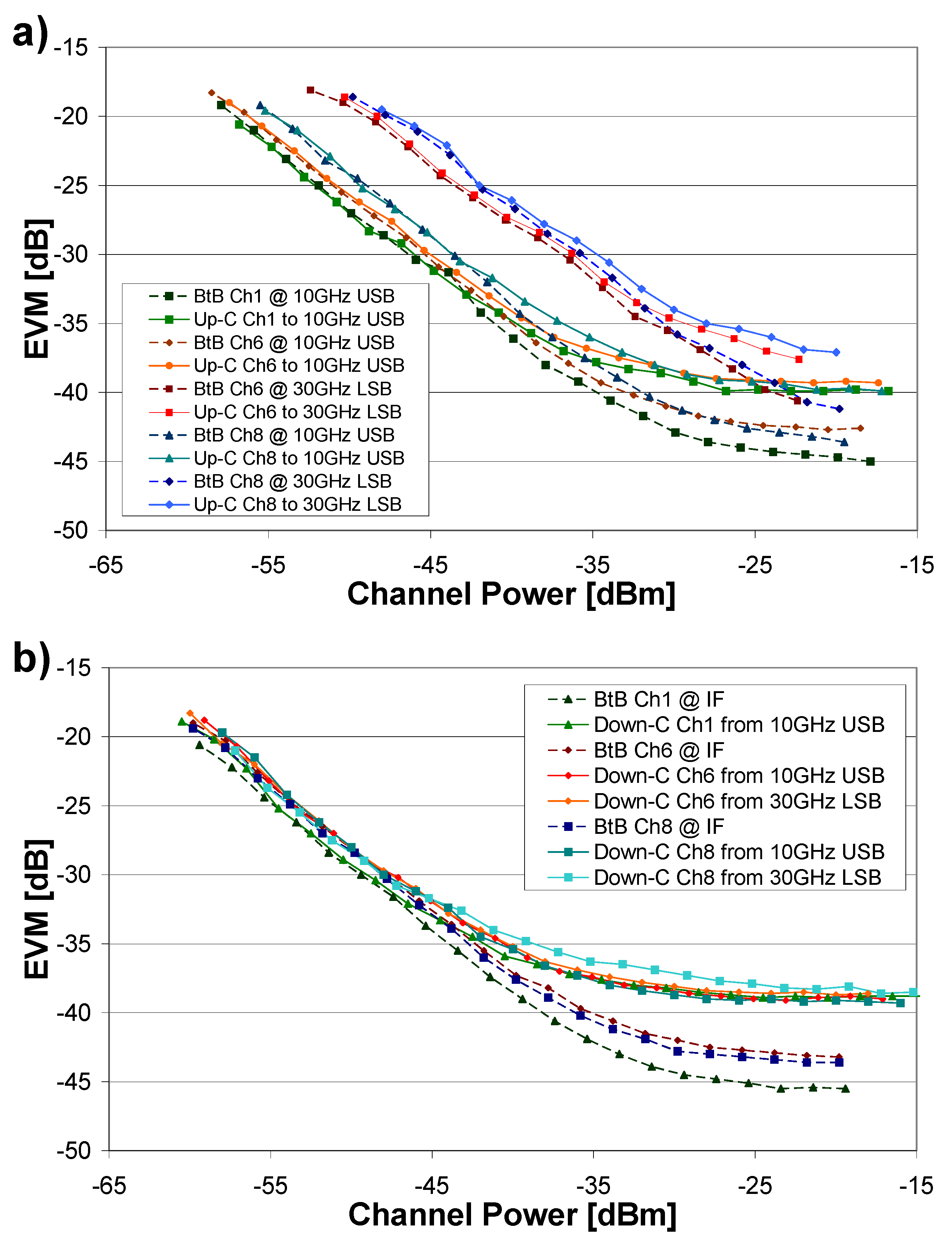
Figure 3a depicts the EVM of three up-converted channels, at IF = 0.9 GHz, 3.32 GHz, and 4.29 GHz,
i.e., channels 1, 6, and 8 respectively. The channels are directly generated at IF by the VSG and then up-converted as 10 GHz USB replicas (10.9 GHz, 13.32 GHz, and 14.29 GHz respectively) and as 30 GHz LSB replicas (in this case, due to the VSA bandwidth limitations, only channels 6 and 8 are reported, at 25.71 GHz and 26.68 GHz respectively). In order to compare the photonic up-converter with the electronic RF generation,
Figure 3a reports also the EVM of the same signals directly generated at RF frequencies.
As shown by the EVM curves, the performance difference between the two methods is negligible, except for the different floor level shown for high power values. This is likely to be ascribed to the saturation of the TIA at the VSA input and to the time/amplitude jitter of the laser. Actually, as discussed in the following, this difference does not represent an issue, as the 802.11 g standard defines the error-free working region for power values corresponding to EVM < −25 dB. As shown in
Figure 3a, the curves corresponding to 25.71 GHz and 26.68 GHz present a power offset,
i.e., increasing the frequency the power needed to obtain a certain EVM also increases. This behavior is due to the different sensitivity of the VSA, as also deducible from the noise floor characteristic in
Figure 2b.
Figure 3b reports the EVM of the photonic down-conversion of channels 1, 6, and 8 (which are electronically generated by the VSG at the 10 GHz USB and 30 GHz LSB frequencies), to IF, compared with the channels generated and received directly at IF. Here again, except for the higher floor reached in correspondence of high input power levels of the optically down-converted channels, the EVM curves show low penalty with respect to the electrically generated signals.
Figure 3.
(a) Error vector magnitude (EVM) of channels 1, 6, and 8 up-converted to two different frequencies. Comparison between photonics-assisted up-conversion (Up-C) and electronic generation (BtB); (b) EVM of channels 1, 6, and 8 generated at IF (BtB), and of the same channels down-converted back to IF (Down-C) from higher carrier frequencies.
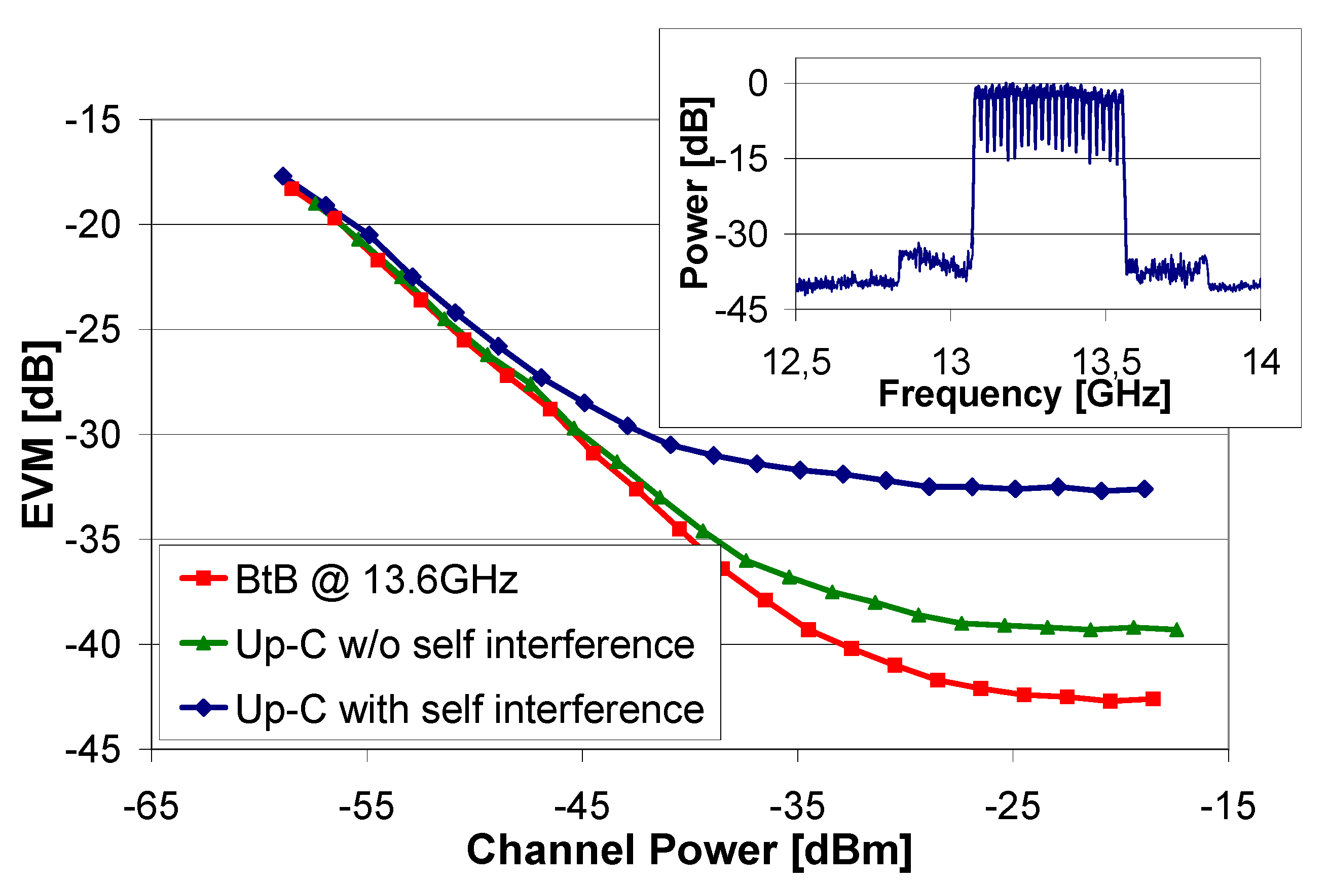
Since the system is designed to occupy the whole available bandwidth, second and third order distortions, caused by MZM non-linearity or higher order beatings, may cause cross-talk or self-interference on the up- or down-converted signals. To better evaluate the system behavior under this condition, a channel centered around 3.333 GHz and up-converted to 13.333 GHz has been considered. This represents the worst case, because such a channel overlaps with the third harmonic of the 20 GHz LSB, as well as with all the beatings components generated by the interaction of the USB around the
N-th laser mode with the LSB of (
N + 1)-th mode in the optical spectrum.
Figure 4 reports the EVM curves of the considered worst case up-converted channel, compared with a detuned channel which does not suffer from distortion. Though the distorted channel presents a higher EVM floor, the power penalty for lower EVM values is again negligible. Moreover, as shown in the inset in
Figure 4, also in this case a high signal-to-noise-and-distortion ratio is still preserved.
Figure 4.
EVM for the channel with worst case self-interference, obtained with optical up-conversion and compared with an electric (BtB) one. The comparison with the EVM curve of a self-interference-free channel is also shown. Inset: 13.333GHz channel spectrum.
Figure 4.
EVM for the channel with worst case self-interference, obtained with optical up-conversion and compared with an electric (BtB) one. The comparison with the EVM curve of a self-interference-free channel is also shown. Inset: 13.333GHz channel spectrum.
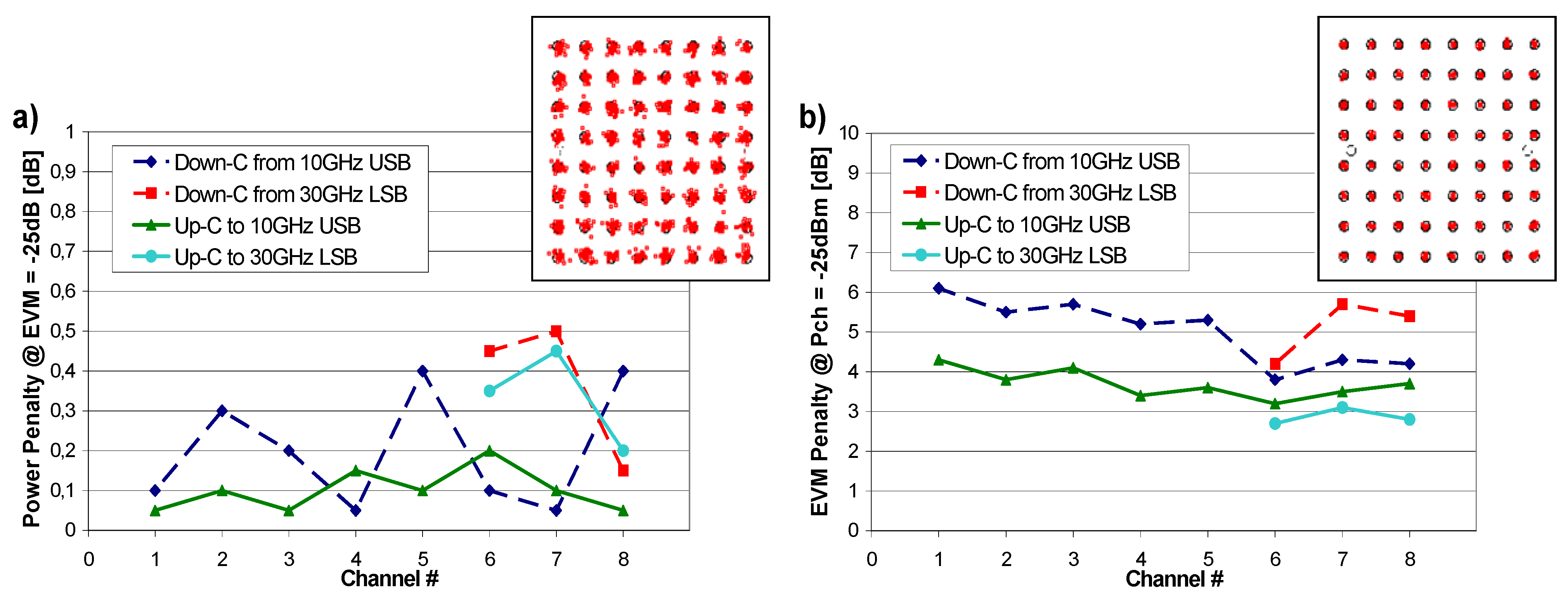
The power penalty induced on each channel by the up- and down-conversion processes, is explicitly shown in
Figure 5a. In compliance with the 802.11 g standard, it is measured as the difference between the minimum power needed for a given channel, directly generated at its carrier frequency, to obtain EVM = −25 dB and the minimum power needed to obtain the same EVM for the corresponding optically up-converted (or down-converted) channel.
Figure 5.
(a) Power penalty in up- and down-conversion for every up- or down-converted channel (Up/Down-C) to or from different frequencies. Inset: detected constellation for a received EVM of −25 dB; (b) EVM penalty measurements for a received power of −25 dBm, in up- and down-conversion for every channel up- or down-converted to or from different frequencies. Inset: detected constellation for a received power of −25 dBm. The channels are numbered in order of increasing IF.
The power penalty measure, performed for the 10 GHz USBs components (
i.e., from 10.9 GHz to 14.29 GHz) and for the 30 GHz LSB components (
i.e., from 25.7 GHz to 26.5 GHz), corresponding to channels from 1 to 8, never exceeds 0.5 dB. Finally,
Figure 5b reports the EVM penalty for a received channel power of −25 dBm, in the same condition as before. This power value has been chosen since, under this condition, all the measured EVM curves have already entered their floor region. In any of the analyzed cases, the EVM penalty varies in a maximum range of 2 dB, showing smaller values for the up-converted channels at any considered frequency. This can be explained considering that, in the down-conversion process, the signal to be down-converted is first electronically up-converted inside the VSG, and this slightly lowers the RF signal quality with respect to the reference signal generated at lower frequency.
4. Conclusions
We have demonstrated the operation, with negligible power penalty, of an UWB photonic-assisted system for simultaneous multi-band up- or down-conversion of wireless signals. The scheme is based on the modulation of the modes of a MLL in a MZM, and exploits the heterodyning of the optical signals in a photodiode. The large optical spectrum of the MLL and the wide electro-optical bandwidth of the MZM and of the photodiode allows us to use the scheme either as an up- or down-converter of RF signals up to the MMB. The presented system has been tested up to 26.5 GHz, showing a negligible power penalty, always lower than 0.5 dB in transmission as well as in reception operations. Since the same device can act both as an up- and down-converter, two of them can be employed, sharing a single MLL, to build a complete transceiver. If a broad-bandwidth photoreceiver (100 GHz photodiodes are commercially available) and an E/O modulator are used, the presented system can work at frequencies well beyond the 26.5 GHz tested in the proposed experiment, thus enabling the implementation of multi-band, multi-protocol transceivers for future mobile networks. Since the photonic integration of MLLs, electro-optical modulators and photodiodes is possible, an integration of the whole system can be considered as a viable solution for developing single multi-band transceivers, suitable for base stations as well as for portable devices.

