1. Introduction
Photonic technologies provide high bandwidths and low attenuation. Hence, they are of high interest for the distribution of wireless data using advanced Radio-over-Fiber (RoF) networks with remote central stations and cost-effective antenna sites [
1,
2]. The highest level of convergence can be achieved by Fiber-to-the-Antenna (FTTA) setups. FTTA systems consist of fiber-coupled Rx and Tx antennas and a fiber network connecting the antennas with the central station (CS) of the RoF system.
Integrated fiber-coupled single-element Tx antennas have been proposed with the optoelectronic conversion (photodiode with fiber pigtail) located at the feeding point of the antenna [
3]. Compared with a single element solution, the beam pattern can be adjusted and more degrees of freedom for the design are obtained using antenna arrays. In phased array systems, photonic beamforming networks exhibiting true time delay (TTD) techniques have been used [
4,
5]. These antenna systems employed electrical feeding lines to the radiating elements [
6] that suffered from losses and other imperfections.
The authors previously demonstrated a lightweight and broadband transmitting antenna with combined photonic feeding and beamforming [
7,
8]. Fiber-coupled photodiodes were located directly at the feeding point of the antenna elements of the array. The beamforming network was realized by optical fibers. This meant that the RoF central station may be located up to several kilometers away from the antenna site.
The weak received radio signal of Rx antennas needs to modulate an optical carrier. Electro-absorption modulators have been used [
9,
10]. This approach implied the use of an external laser source. Additionally, realizing advanced antenna structures that provide more gain, higher bandwidths,
etc. is challenging with that approach. A highly integrated solution comprising a VCSEL and a patch antenna was presented in [
11]. However, multimode VCSELs have a different emission wavelength and are not suitable for standard single mode fiber networks.
The authors also presented an active fiber-coupled antenna in which the complete circuitry to convert the received radio signal to the optical domain was integrated on the antenna [
12]. A fiber-coupled laser diode as well as its driver and preamplifiers were integrated onto the Vivaldi antenna PCB. A high relative bandwidth of 133% could be reached. It has been shown (e.g., for UWB applications [
13]) that the existing antenna dispersion of Vivaldi antennas used in our Rx and Tx antennas can be neglected. Thus, one does not expect to see effects due to antenna dispersion.
In [
14], a UWB over Fiber system was realized. However, there was no back channel from the remote site to the central station,
i.e., only a fiber-coupled remote Tx antenna was realized. Moreover, a commercial Tx antenna was used, and was therefore not integrated with the optical receiver. Lee
et al. [
15] also demonstrated only downlink functionality with a fiber-coupled remote Tx antenna. FTTA systems with integrated Rx and Tx antennas have been shown in the context of high carrier frequencies where even short electrical waveguides cannot be used [
16]. Few full-duplex systems have been built with horn antennas where the optical receiver is externally connected [
17]. A complete system is proposed in [
18] but was only measured without wireless link (
i.e., without antennas). In [
19], a wireless link was included but due to only MHz bandwidth just IEEE 802.11 Wireless LAN was supported.
We demonstrate a complete full-duplex FTTA system with integrated fiber-coupled Rx and Tx antennas. Also, a central station providing RF upconversion and downconversion was added in this paper. Using the previously introduced antennas and optical feeding network [
7,
8,
12], a complete system setup is assembled that is capable of broadband multi-standard transparent transmission. The antennas are directly connected to a standard single mode fiber network. The frequency range of the antennas includes GSM, UMTS, LTE and WiFi frequencies. Due to the broadband system design (500 MHz to 2.5 GHz), a variety of existing standards is supported by the low-cost PCB antennas. Metro network transmission distances (
i.e., tens of kilometers) between the Central Station (CS) and the fiber-coupled antennas are experimentally researched. Consequently, a complete RoF link from the central station to the base station, a wireless transmission and the transmission from the base station back to the central station is investigated.
At first, the developed components and the system setup are summarized. In the second part, the experimental FTTA system demonstration results are discussed.
2. Components and Setup
A FTTA system for wireless applications consists of different building blocks. In the CS, the sophisticated equipment (e.g., RF components, electronic equalization and signal processing,
etc.) is concentrated. The potentially high number of Base Stations (BS) should be simple and cost-effective. Therefore, antennas with integrated optical interfaces have been proposed and are discussed in detail in
Section 2.1 and
Section 2.2. The wireless signals are transported transparently over the fiber, so that the compatibility to existing Mobile Stations (MS) is ensured.
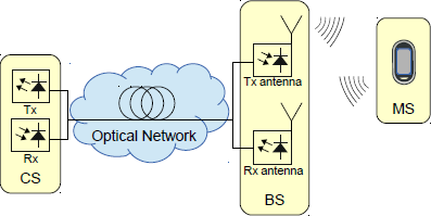
Figure 1 summarizes the general setup of such an RoF–FTTA system.
Figure 1.
RoF–FTTA system overview: Central Station (CS), Optical Fiber Network, Base Station (BS) with fiber-coupled Rx antenna and Mobile Station (MS).
Figure 1.
RoF–FTTA system overview: Central Station (CS), Optical Fiber Network, Base Station (BS) with fiber-coupled Rx antenna and Mobile Station (MS).
In the CS, the wireless signal is generated, i.e., the data is modulated on an electrical carrier according to the wireless standard. This signal is amplified and modulated on an optical carrier for transport over existing fiber infrastructure. Usually, a DFB laser diode serves as optical source due to its superior cost and performance features. This RF-over-Fiber scheme ensures the most simple BS configuration providing an RoF signal. The CS also converts the received RoF signal back to electrical domain using a photodiode and demodulates the electrical signal to retrieve and further process the data.
A full-duplex operation of the BS is provided by separate Rx and Tx antennas. The Tx antenna receives the optical downlink data from the CS and converts it to the electrical domain using a photodiode located at the feeding point of the antenna. The Rx antenna receives the wireless signal from the MS. It is amplified and modulated on an optical carrier (DFB laser diode) onboard the antenna PCB for uplink transmission to the CS. The single mode fiber (SMF) network has a flat frequency response due to its broadband behavior. For transmission distances within tens of kilometers, chromatic dispersion is not an issue. The typical attenuation of a SMF is 0.2 dB/km.
2.1. Tx Antenna
After transmitting the RoF signal generated in the CS over an existing SMF link, the modulated RF signal has to be converted back to the electrical domain and fed to an antenna for wireless radiation. Photodiodes convert the incoming RoF signal from the optical domain to the electrical domain. Antenna arrays may provide beamforming, beam steering and beam switching. By using an optical beamforming network true time delay (TTD) is provided. A minimum of electronics and RF wiring can be achieved at the BS by placing the photodiode directly on the feeding point of the antenna. We demonstrated such Tx antenna arrays in [
7,
8]. The direct connection of the photodiode to the feeding point of the antenna limits the transmission power of the antenna to the output power of the photodiode,
i.e., a few milliwatts. Consequently, the transmission distances will be restricted. The authors decided to nevertheless follow this path for the subsequent reasons: (1) Mounting the photodiode at the feeding point of the antenna is the highest possible degree of integration. This was one of the research goals of the authors that required a different design than traditionally fed active antennas with power amplifiers as last stage (e.g., [
20]); (2) FTTA configurations with highly reduced amount of electronics are especially of interest for indoor applications where a high number of simple Tx stations are needed. In this scenario, only low powers are needed and the few mW provided by only the photodiode is sufficient; (3) For measurement purposes, lower powers are easier to handle in the (unshielded) lab because the risk of jamming commercial services within the frequency range of the antenna is reduced.
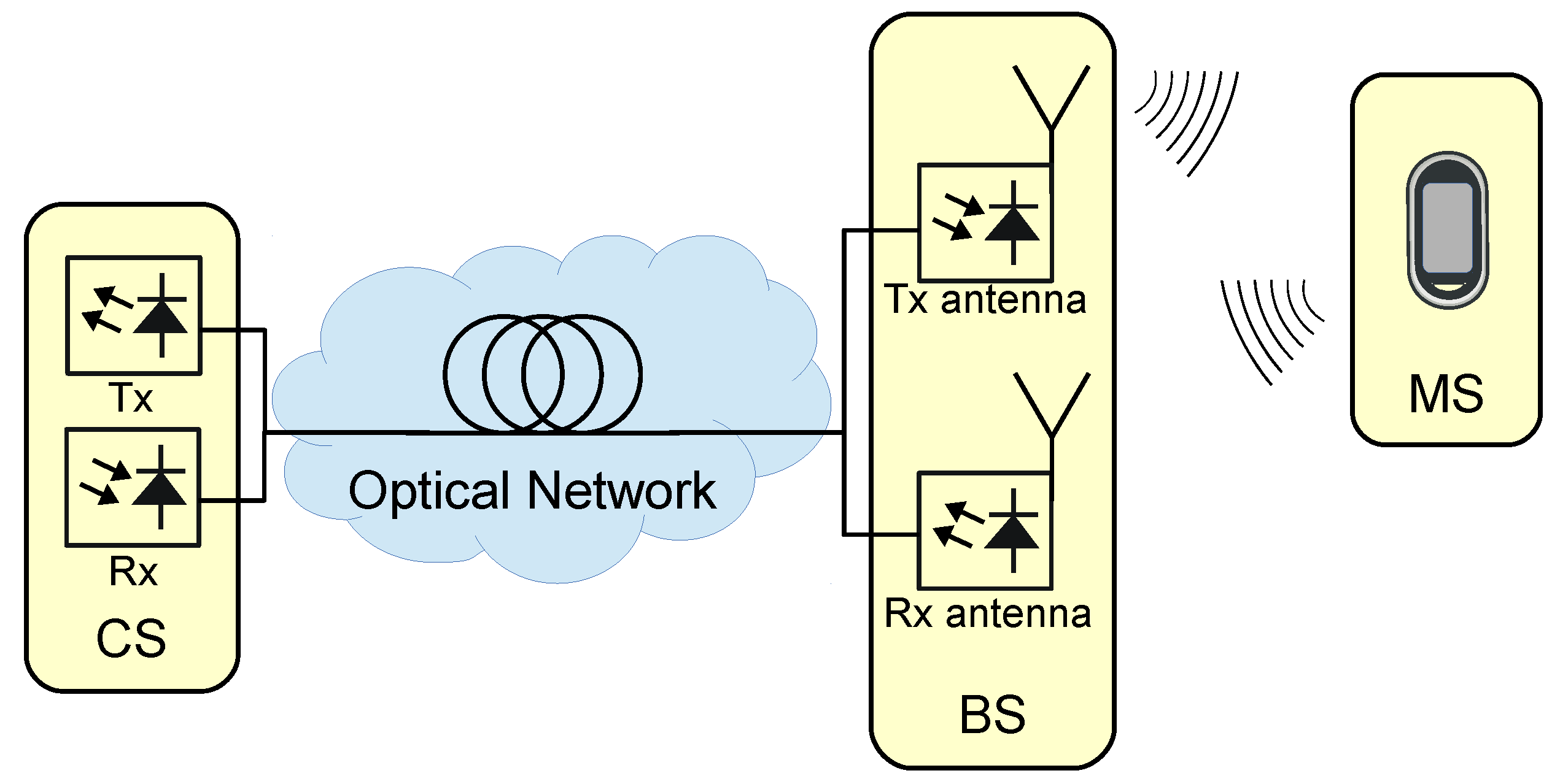
Here, a 2 × 1 Tx antenna array configuration is used. The antenna is shown in
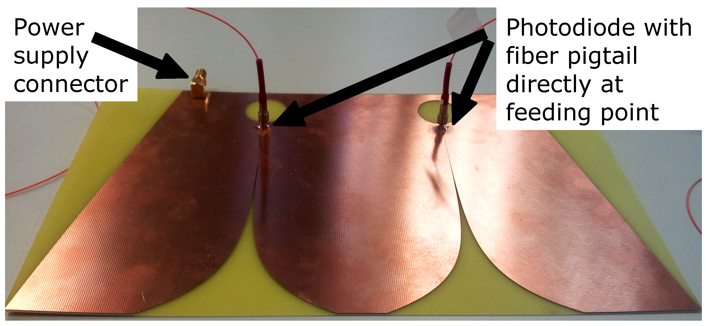
Figure 2 and the corresponding photonic beamforming network is depicted in
Figure 3. A 3 dB coupler splits the optical input into two paths. A path length difference
can be added to the length of the beamforming network
before being connected to the fiber-coupled antenna elements (fiber length
) to provide a true time delay. Note that for the experiments discussed in
Section 3, the beamforming network was configured to radiate straight on with an antenna gain of 6 dBi (
) at the center frequency. The losses of the short (<1 m) fiber lengths
,
and
can be neglected. Details of the beamforming network can be found in [
7].
Figure 2.
2 × 1 antenna array fed by photodiodes connected by optical fiber.
Figure 2.
2 × 1 antenna array fed by photodiodes connected by optical fiber.
Figure 3.
Photonic beamforming network for 2 × 1 antenna array ( in experimental setup).
Figure 3.
Photonic beamforming network for 2 × 1 antenna array ( in experimental setup).
2.2. Rx Antenna
The Rx antenna of the BS is more sophisticated than its Tx counterpart. It has to receive the electromagnetic waves and enable RoF transmission over SMF to the CS. Due to the low Rx powers of wireless transmissions, the electronic circuit is designed using a multi-stage approach. An LNA (HMC639ST89E) is followed by a limiting amplifier (TI ONET4201PA) to provide the required input levels for the laser diode driver (TI ONET4201LD) (200–1600 mVPP) connected to a DFB laser (AOI DFB-1550-C5-2-A4-FA-A-A). The laser diode driver circuit is able to produce a bias current in the range of 13–55 mA. A bias current of 28 mA was set and lead to a laser power of about 2 mW. The modulation current can be adjusted in the circuit in 6–60 mA. To realize a high modulation depth, it was set to 16 mA. All this circuitry could be integrated on a PCB that also holds the antenna.
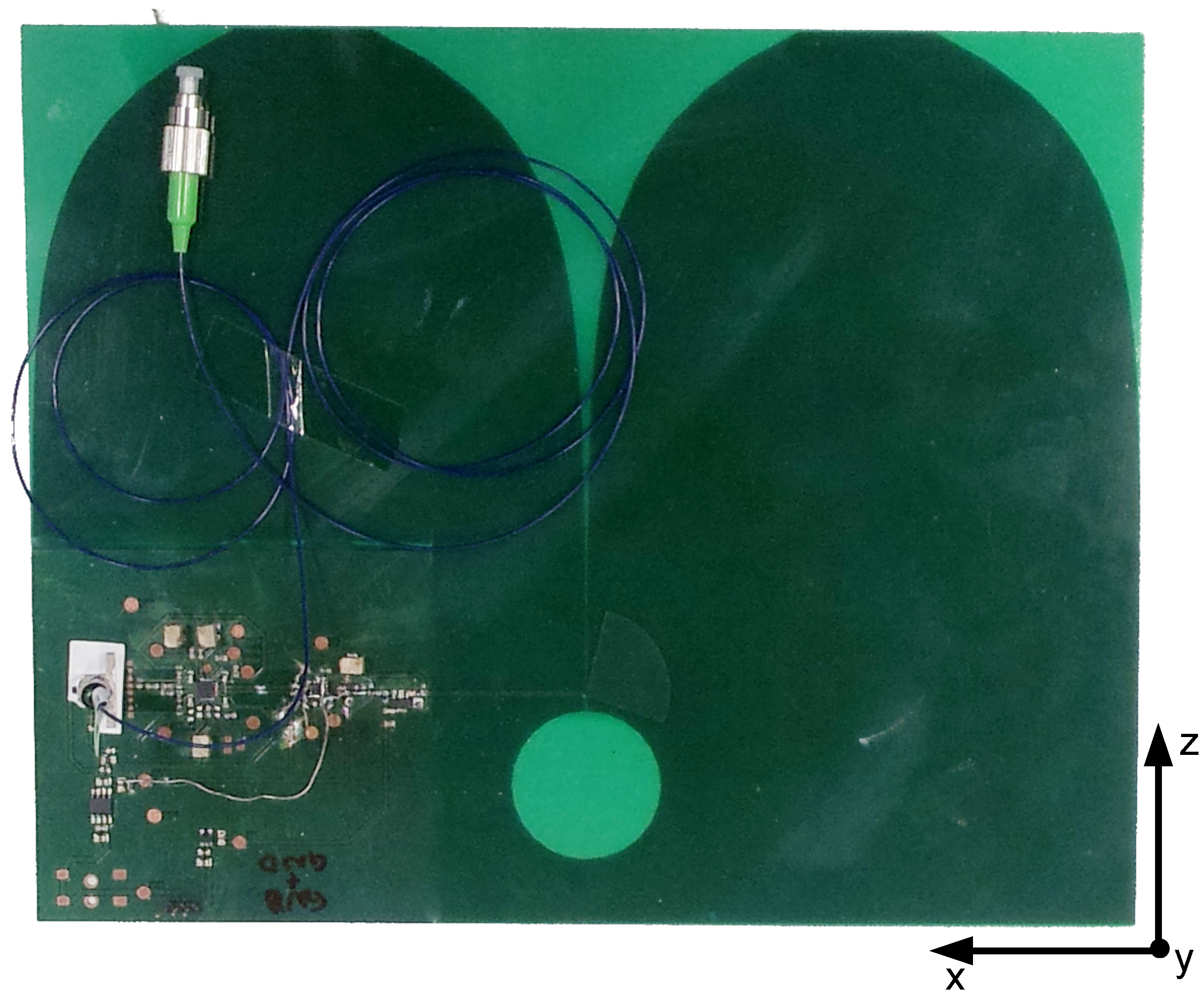
Figure 4.
Back side of antenna with electronic circuit and radial stub.
Figure 4.
Back side of antenna with electronic circuit and radial stub.
The higher complexity of the Rx antenna makes it difficult to realize an antenna array. The relative phase information between all receiving antenna elements would have to be maintained throughout the reception, electro-optical conversion, optical transmission and reception in the CS to enable a correct recombining. This implies an extensive calibration procedure of the whole system from BS to CS. Antenna combining at the BS conflicts with the aim for a simple BS architecture. Hence, only a single-element Rx antenna is used in our FTTA demo system.
Figure 4 depicts the Rx antenna including the electronics and the laser diode with an SMF pigtail that can be directly connected to a state-of-the art SMF optical network. The detailed circuit configuration is discussed in [
12].
Input power levels as low as −50 dBm are supported in this configuration. The Rx antenna itself has a frequency-dependent gain of 2 dBi at 500 MHz and 6 dBi at 2.5 GHz. However, being directly connected to the amplifiers and the laser diode driver and the DFB laser, this is not a directly measurable quantity anymore. Within the whole electrical-optical-electrical setup (i.e., after the receiving photodiode in the CS), the most interesting feature is the frequency characteristic because it determines the possible applications for the FTTA system.
2.3. Frequency Characteristics
The frequency characteristics of the active Rx and Tx antenna systems were measured using a network analyzer (NWA). For the Rx antenna system, the output port was connected to a test antenna and the input port was attached to a photodiode that converted the optical output signal of the active Rx antenna to electrical domain. The characteristics of the test antenna and the photoreceiver (Agilent 83411D) were known so that their influence could be calibrated out. The transfer function of the active Rx antenna system could be obtained as a result. The measured frequency characteristic can be seen in
Figure 5.
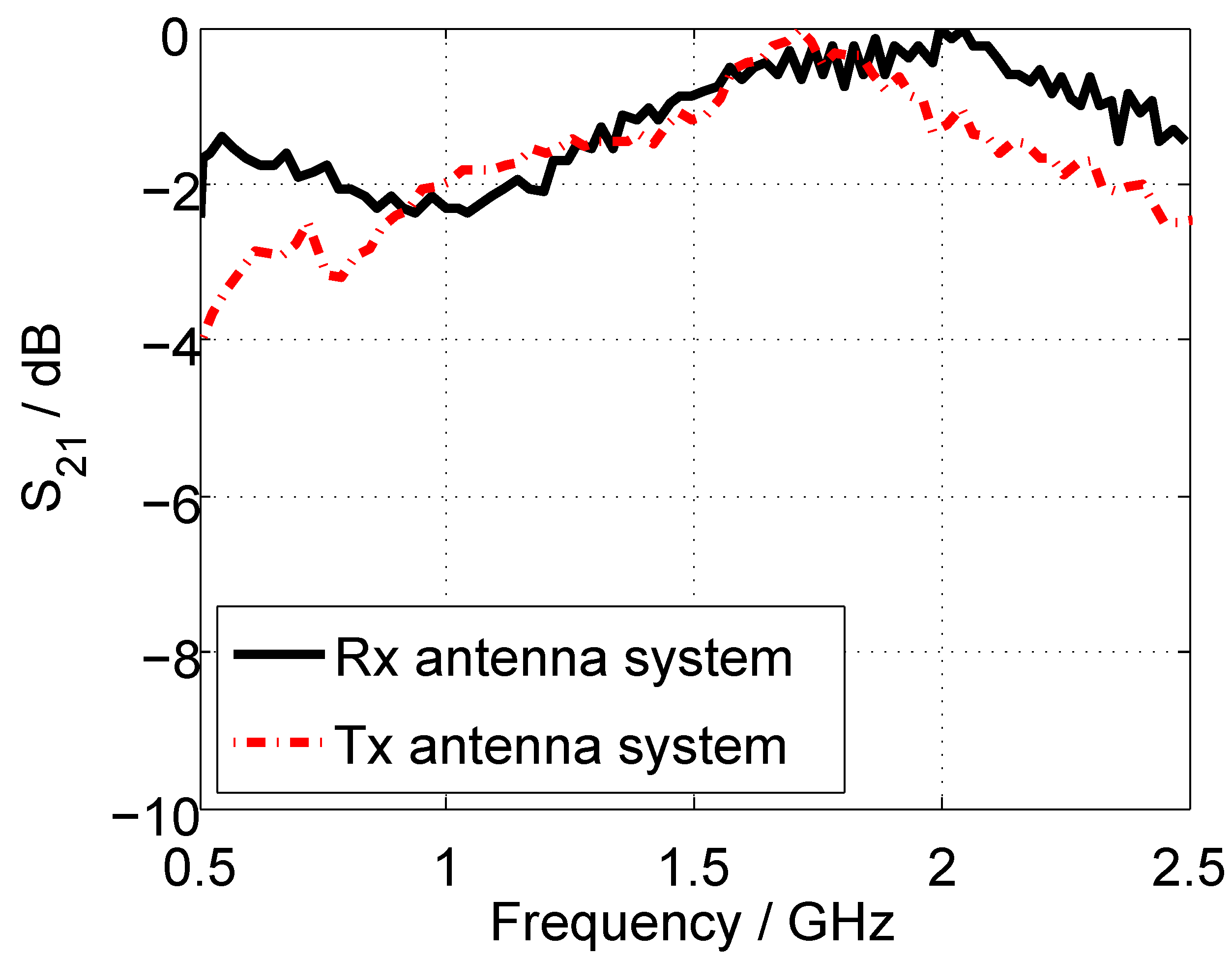
Figure 5.
Frequency characteristics of the fiber-coupled active antenna system: Rx antenna (black, solid), Tx antenna (red, dashed).
Figure 5.
Frequency characteristics of the fiber-coupled active antenna system: Rx antenna (black, solid), Tx antenna (red, dashed).
An extremely high relative bandwidth could be reached: From 500 MHz to 2.5 GHz, the frequency response is flat. While the antenna gain increases with frequency, the gain of the amplifiers and also the modulation response of the laser diode decrease. That means the upper frequency limit is determined by the electronic components and the lower frequency limit is determined by the antenna (matching and gain). Therefore, a 2 GHz bandwidth is available and the carrier for the FTTA demonstration (
Section 3) will be set to 1.5 GHz.
For the Tx antenna system, the output of the NWA was connected to an optical source module (Agilent 83403B) converting the electrical signal into the optical domain. Its input port was attached to a test antenna. With the known characteristics of the test antenna and the optical source module, the frequency characteristic of the antenna system could be measured as shown in
Figure 5. As for the Rx antenna system, the lower frequency limit is determined by the antenna and the upper frequency limit is set by the lowpass behavior of the photodetector. The higher gain of the antenna at higher frequencies again enables a wide range of operation (3 dB) of 600 MHz up to more than 2.5 GHz.
2.4. Nonlinear Behavior
Nonlinearities can be an issue especially for multi-carrier systems with strong tones due to intermodulation. In microwave photonic links, a huge number of components have nonlinear behavior and introduce distortions. The optical transmitter in the base station has a nonlinear characteristic, regardless whether a directly modulated laser (exponential function) or an external modulator (cosine function) is used. The transimpedance amplifier of the photoreceiver is nonlinear, but is negligible in comparison with other building blocks. Most of the nonlinearities in our configuration are introduced by the limiting amplifier in the Rx antenna. Also, the directly modulated laser diode (including driver amplifier) adds nonlinearities.
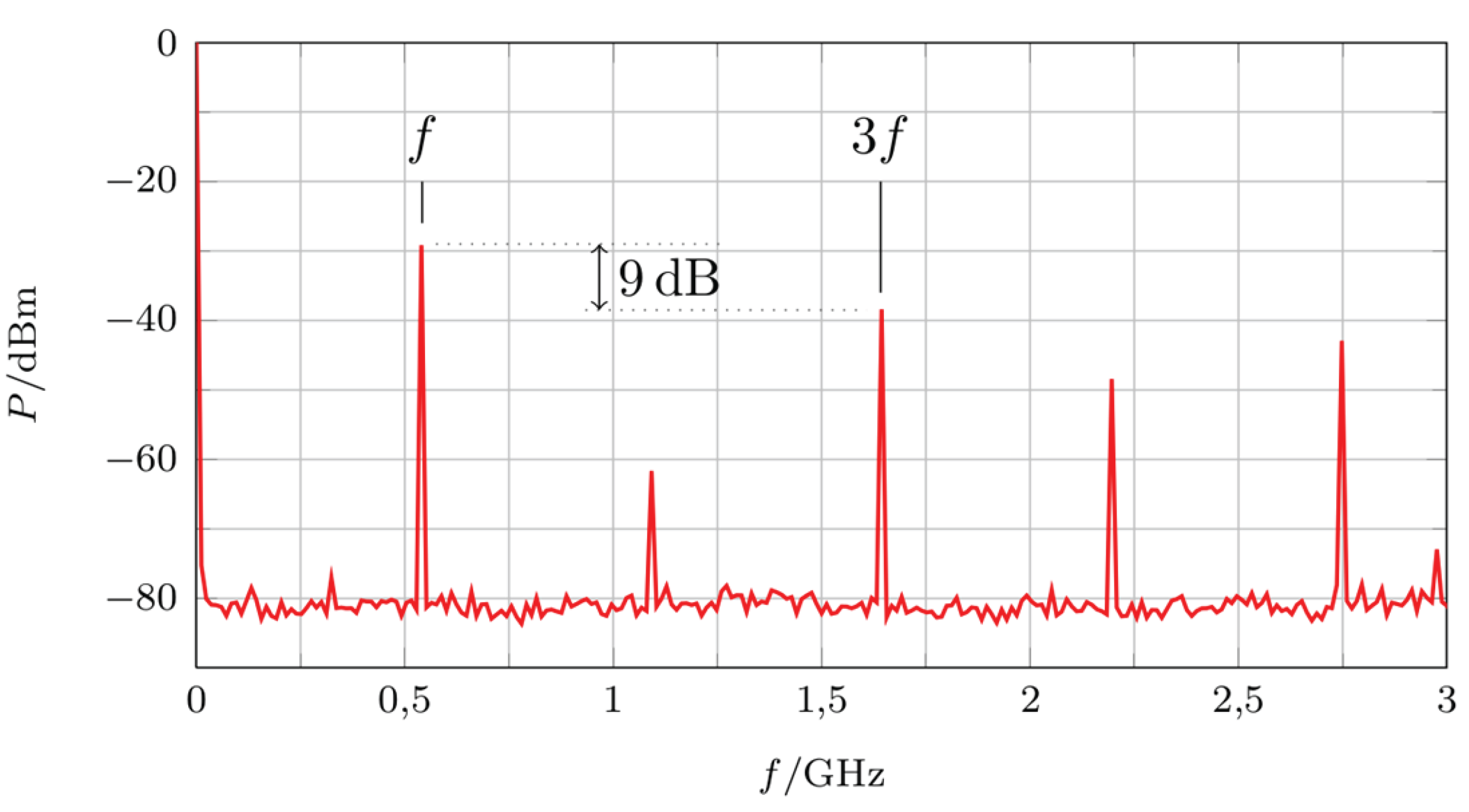
Figure 6.
Measured spectrum for single tone excitation.
Figure 6.
Measured spectrum for single tone excitation.
As can be seen in
Figure 6, the system was not optimized for linear behavior. The third order harmonic is only 9 dB weaker than the fundamental tone. Replacing the cost-effective off-the-shelf components for digital systems with specialized components for analog systems would lead to a more linear performance. However, the eye diagrams do not indicate any major impact but as mentioned before the case of multiple strong tones might be more severe and is planned to be researched in more detail.
3. FTTA System Demonstration
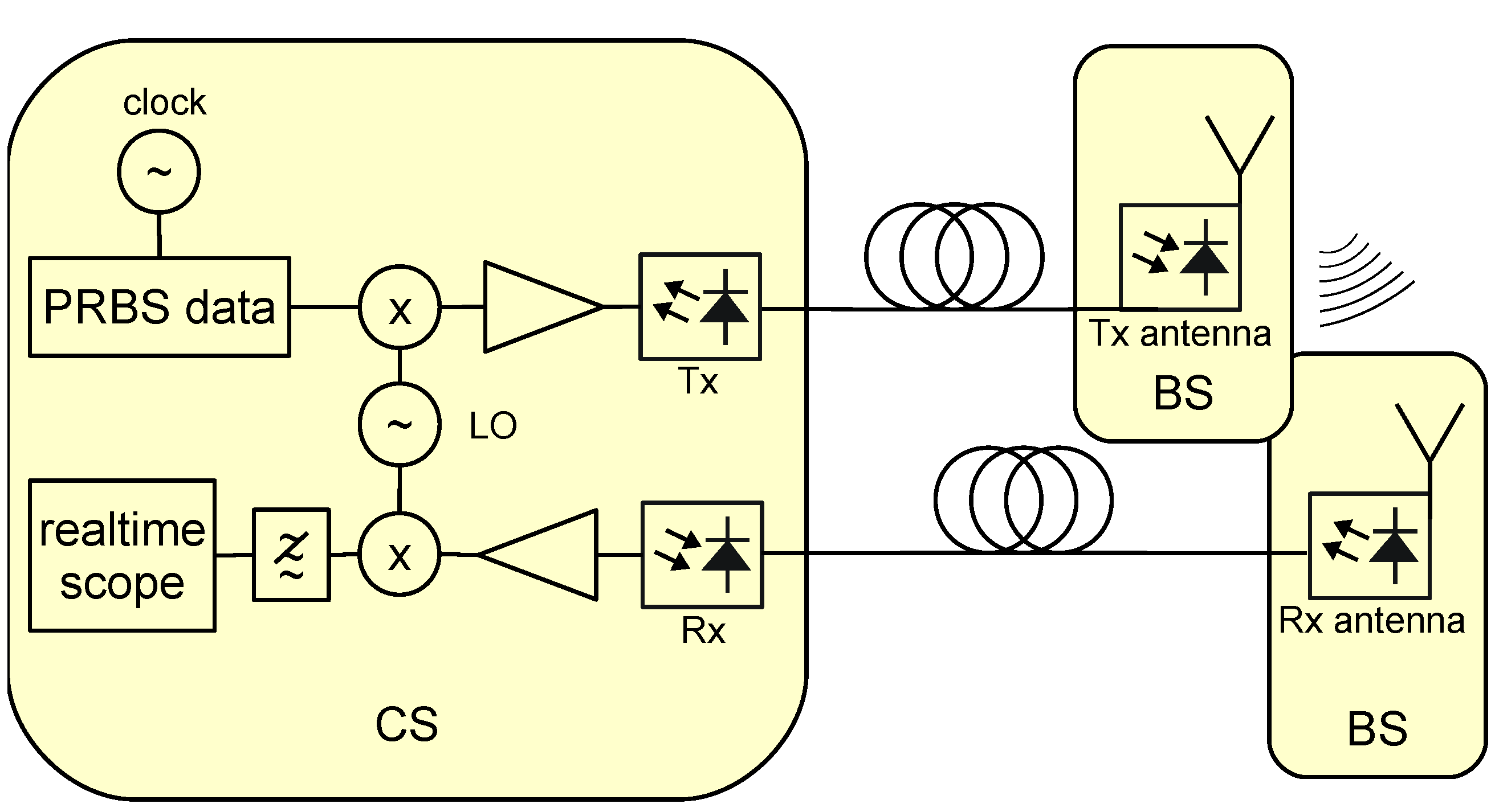
Figure 7 shows the experimental setup. A Centellax PRBS generator with adjustable bit rate was used as data source. Only simple NRZ OOK modulation was used for the sake of simple system architecture. A mixer (MiniCircuits ZX05-42MH) upconverted this signal for the experimental results shown here on a 1.5 GHz carrier (Rohde & Schwarz SML03). This carrier frequency is centered within the frequency range of operation of the antenna systems and ensures maximum bandwidth. Note that transmission of high data rates over a single carrier is the most critical case for the channel since it should be flat over the whole bandwidth. Data rate and spectral efficiency could be increased by using IQ mixers in conjunction with advanced modulation formats such as QPSK. After amplification (2× PicoSecond Pulselabs 5828-108), the signal was directly modulated on a laser diode and fed into a standard single mode fiber (SMF) span (25–50 km). At the end of the span, the optical signal was fed into the 2 × 1 Tx antenna array introduced in
Section 2.1. The optical beamforming network was configured for an angle of 0°. Note that the antenna also serves here as highpass filter neglecting the remaining baseband after the upconversion.
Figure 7.
Block diagram of experimental setup.
Figure 7.
Block diagram of experimental setup.
After wireless transmission in the range of meters (due to Tx power restrictions to a few mW), the signal was received by the Rx antenna (
Section 2.2). This antenna is coupled to an SMF span (0–20 km). The lower output power of the laser diode integrated on the antenna causes a lower possible transmission length back to the central station. There, the signal is received by a photodiode, amplified (PicoSecond Pulselabs 5828-108 + MiniCircuits ZJL-7G), mixed (MiniCircuits ZX05-42MH) with the LO and lowpass filtered to avoid the mirror frequencies. The eye diagrams were generated using an Agilent 90804A realtime scope.
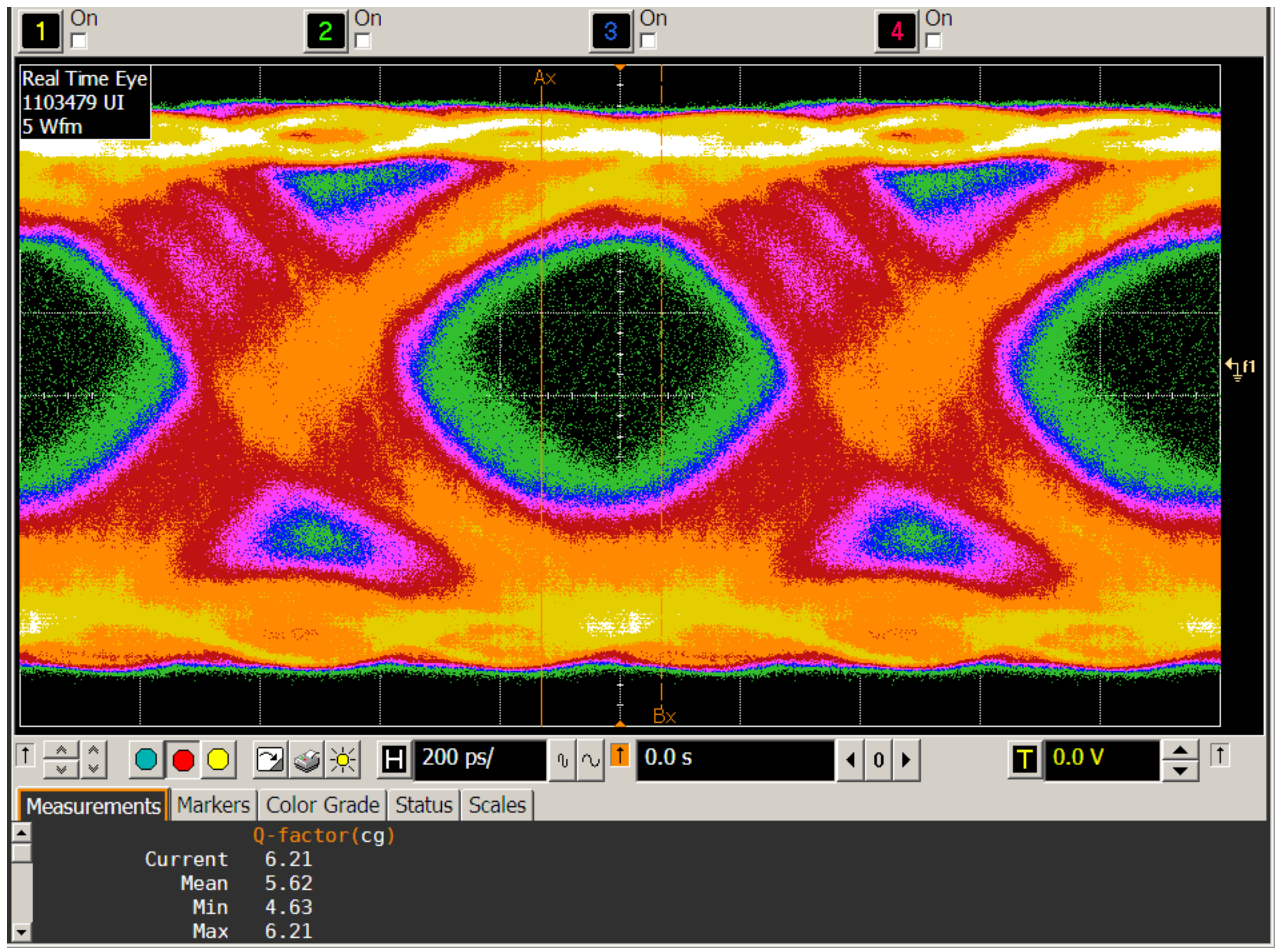
Figure 8 shows the eye diagram of the highest data rate that could be achieved using this setup. At 1 Gbit/s, an average Q factor of 5.6 could be reached, which corresponds to a BER of
. The system was at its bandwidth limit when being operated at the data rate of 1 Gbit/s. This caused a deterioration of the signal-to-noise ratio. Thus, only shorter transmission distances could be demonstrated. The more sophisticated optical Tx in the CS allowed a distance of 25 km between CS and optical Tx antenna. When the received signal at the CS is too weak, LO interference after mixing impairs the eye diagram. Therefore, the distance between Rx antenna and CS had to be set to only tens of meters for an acceptable BER.
Figure 8.
Eye diagram of received signal at 1 Gbit/s.
Figure 8.
Eye diagram of received signal at 1 Gbit/s.
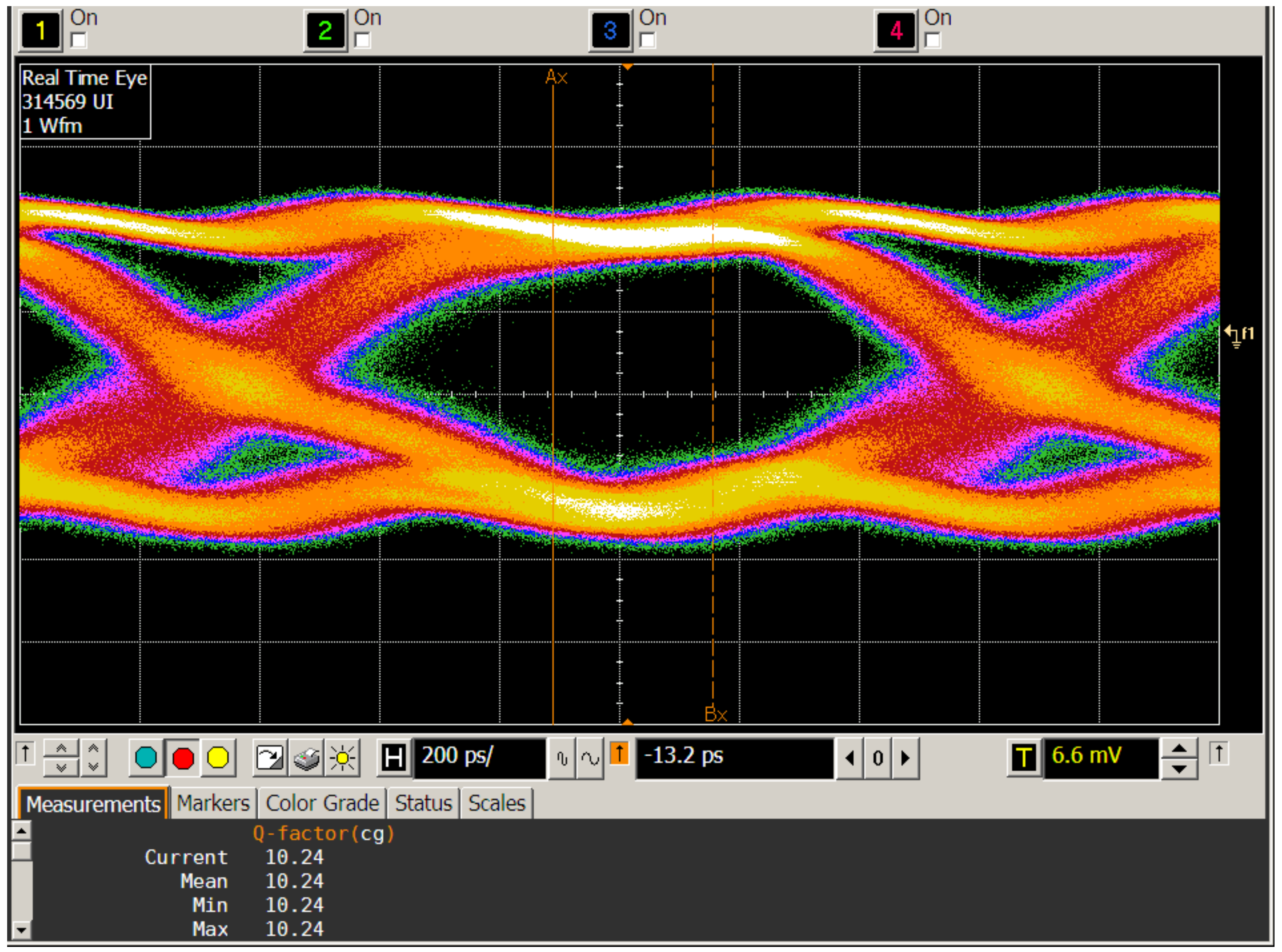
Lowering the data rate relaxes these issues and allowed for configurations with longer optical spans. Ranges within typical metro networks were demonstrated: 45 km (CS-Tx) + 10 km (Rx-CS). The results are shown in
Figure 9: 750 Mbit/s NRZ OOK transmission with a Q factor of 10.2 was possible. An alternative configuration with 25 km (CS-Tx) + 20 km (Rx-CS) leads to a Q factor of 8.2, also providing error-free transmission.
As expected, no effects due to the antenna dispersion could be noticed. Using a carrier frequency of 1.5 GHz and transmission distances of less than 60 km, also no effects of the chromatic dispersion of the optical fiber could be observed. The high relative bandwidth of the system of 133% should be noted.
Services with smaller bandwidth (e.g., GSM) are less vulnerable to channel issues because the channel only has to be flat in a smaller frequency range. In addition to the electronics and the radio channel, also the optical channel may contribute to distortions. The setup with the carrier at 1.5 and the 2 GHz bandwidth shows good BER results. So, for narrowband services no major impact is expected. In addition, from the frequency characteristic measurement no deterioration is foreseen. Note that with lower data rates (e.g., 500 Gbit/s) carrier frequencies down to 1 GHz and up to 2 GHz have been used without influence on the BER.
The concept can be easily scaled to higher frequencies: Laser diodes that can be directly modulated are available up to 40 GHz bandwidth. The level of integration can be even improved when the operating frequency is increased due to smaller antenna dimensions. This enables applications up to the K band that are very promising for satellite links. Anyway, the cost of the components (laser diodes, substrates, amplifiers, drivers, etc.) scales with frequency. Also, the fiber dispersion becomes an issue at higher frequencies: The most prominent effect will be the phase decorrelation of the two sidebands of the optical signal. That means, achievable transmission distances will be lower, dispersion compensation has to be applied or single sideband modulation has to be used which increases the effort.
Figure 9.
Eye diagram of received signal at 750 Mbit/s.
Figure 9.
Eye diagram of received signal at 750 Mbit/s.
Higher carrier frequencies allow for higher absolute bandwidths resulting in larger data rates. Another way to increase the data rate is the use of sophisticated modulation formats such as mPSK or mQAM. For these formats, it is necessary to have IQ mixers in the upconversion and downconversion stages. However, the RF signals with advanced modulation could be transported transparently over the microwave photonic link. No change in the fiber-coupled active Rx and Tx antennas would be necessary. Just the electronic circuits in the central station would have to be changed, i.e., equipped with IQ mixers and corresponding data sources and sinks.
To serve more than one BS, wavelength division multiplexing (WDM) techniques can be applied, i.e., lasers with different wavelengths will be used. They can be separated by WDM demultiplexers. This way, one fiber can be shared among more than 100 BS. Depending on the network architecture, of course also different fibers can be deployed to the various BS.


