1. Introduction
Various kinds of microstructured optical fibers (MOFs) such as photonic crystal fibers (PCFs) have been developed and applied to a number of industrial fields including telecommunication and sensing [
1,
2]. Polarization maintaining MOFs were also demonstrated [
3]. Starting from all-silica photonic crystal fibers [
4,
5], utilization of functional materials such as chalcogenide glasses in the fiber structure have been successfully demonstrated in experiments [
6,
7]. Recent progress of fabrication technologies made it possible to manufacture all-solid MOFs consisting of chalcogenide glass/silica [
8,
9] and silicon/silica [
10,
11] materials. The experimental feasibility of combining soft and hard glasses such as hybrid silica/tellurite PCF [
12] and hybrid polymer PCF filled with chalcogenide glass [
13] have been already shown. Also, efficient numerical techniques for analyzing MOFs have been reported [
14]. Such all-solid MOFs will open a door to the development of novel functional fiber components as a building block of light sources and sensors.
In [
15,
16] we have reported a new class of confined modes in all-solid MOFs. The fiber consisted of a circularly arranged array of high-index rods (Si) embedded in a low-index host material (silica). Key mechanism of the light confinement is the guided-mode resonance (GMR) [
17] that the rod array exhibits against a cylindrical wave [
18] that forms a transverse fiber mode. Thus we have called it resonantly-guided modes (RGMs). Thanks to the wavelength selective but highly reflective property of GMR, propagation losses of the modes were found to be also sensitive to wavelength. This means that a MOF which supports RGMs functions as a narrow-banded wavelength filter, in which only limited numbers of wavelength can survive after a finite length of propagation. By making use of this nature one can use the MOF as, for example, a building block of high-sensitivity gas sensor (hollow-core type fiber).
In our previous works [
15,
16] we analyzed GMR characteristics of a Si rod array, dispersion relations and losses of TM modes only.
What we have shown so far are some basic propagation characteristics of the RGMs as follows:
However, detailed modal characteristics and relation between the RGMs and conventional fiber modes were not yet studied. In this paper we analyzed modal field distributions and dispersion relations of various modes including hybrid ones. Through that we will classify the RGMs following the conventional mode notation (TE, TM, EH, and HE). Differences between the MOF for RGMs and conventional circular fibers are clarified from a viewpoint of possible supported modes. Results to be shown will help us understand global characteristics of RGMs.
Here we briefly mention the guiding mechanism of conventional all-dielectric circular fibers. In conventional fibers, light field is confined in the core by total internal reflection (TIR). Therefore the refractive index of the core must be higher than cladding. Ray of guided modes makes relatively a small angle with respect to the fiber axis for TIR to be maintained. On the other hand, in MOFs for RGM, light is confined by the reflection due to GMR of the rod array. Requirement is that the index of the rods is higher than the remaining part of the fiber. Ray of the guided mode may make a large angle with respect to the fiber axis. The ray can hit the rods almost perpendicularly, as the GMR is well maintained for such a large angle of incidence.
Note that the confinement mechanism of RGM is also different from ARROW (Anti-Resonant Reflecting Optical Waveguide) modes in MOFs [
20]. The point of their differences, and requirements for a MOF to support ARROW or RGM can be summarized as follows:
- (1)
For a MOF to support ARROR modes, proper refractive index distribution into the radial direction is required. This is because ARROW modes basically rely on multiple interferences toward the radial direction [
20].
- (2)
Refractive index modulation into the angular direction is optional for ARROW. Thus, MOFs with two-dimensional index distribution may support ARROW modes.
- (3)
RGM appears only in MOFs with two-dimensional index distribution. Specifically, a periodic array of high index rods must be embedded in a low index background. RGMs are not supported in azimuthally-uniform fibers.
- (4)
RGMs are formed by the GMR that the rod array exhibits. Only a single ring of the rod array is sufficient to induce GMR.
Note that GMR is a different process from Fabry-Pérot interference. Light is first diffracted by the rod array and couples to a whispering gallery mode (WGM) which travels circularly along the array. The WGM is re-diffracted and radiated toward both inside and outside the fiber. At a resonance condition all the diffracted waves toward inside constructively interfere. This is the reflection by GMR. Thus, if the array is flat, theoretical peak reflectivity reaches as high as 100%. For a curved rod array, peak reflectivity is determined by the bending loss of the WGM.
2. Numerical Analysis
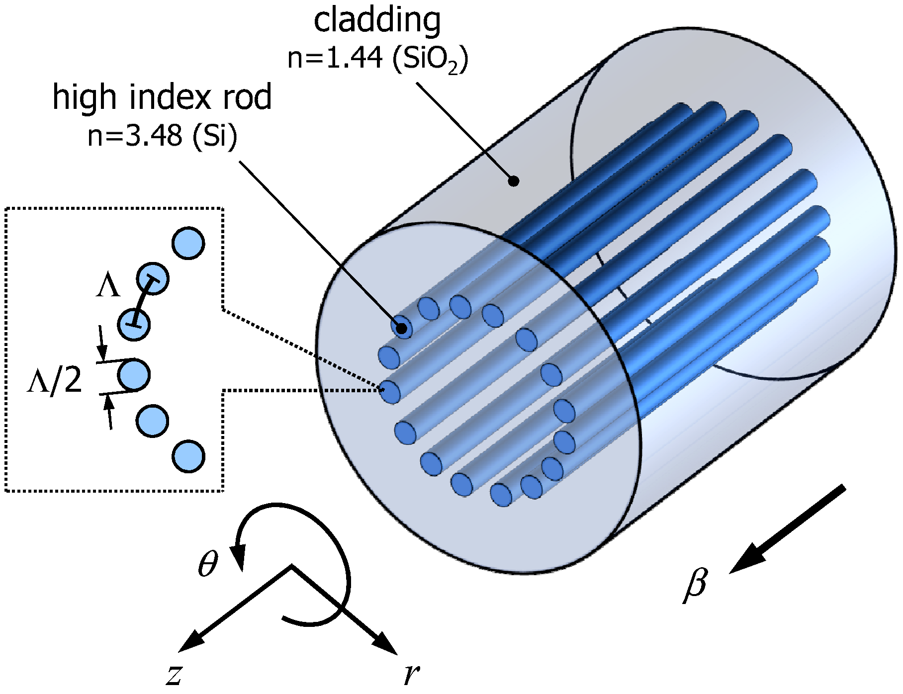
Sample structure of a MOF supporting RGMs is shown in
Figure 1. High index rods (assumed Si,
n = 3.48, diameter =
) are regularly arranged in a low index cladding (assumed SiO
,
n = 1.44) with 10 degrees of azimuthal pitch. Total number of rods is thus 36. The distance between adjacent rods is denoted by Λ. Assuming operation wavelength of λ = 1.55 µm, Si rod diameter is about 500 nm and Λ becomes about 1 µm. These features are still several times smaller than experimentally demonstrated Si MOF [
10,
11]. As the dimensions scale with wavelength, applications using longer signal wavelengths will be preferred from the viewpoint of fabrication. Note that by utilizing higher order GMR, the rod diameter could be increased.
Figure 1.
Refractive index profile of a sample fiber structure. Λ denotes the period of the solid rods.
Figure 1.
Refractive index profile of a sample fiber structure. Λ denotes the period of the solid rods.
In order to utilize the fiber as, for example, a building block of a gas sensor, the fiber has to have a hollow section. This can be achieved by forming a center hole in the presented MOF structure. Even though we made a large hollow core, it will not change the basic waveguiding property of the RGM. This is because the resonant reflection occurs in the vicinity of the periodic Si rod part. The center uniform index region acts only as a propagation space for cylindrical waves.
We calculated dispersion relations and mode field profiles using compact two-dimensional Finite-Difference Time-Domain (FDTD) method for cylindrical coordinate system [
21]. Detail of the analytical space was described in Ref. [
16]. In order to exclude spurious solutions, we need to calculate in a cylindrical coordinate system. In such a case, the computational domain becomes a unit sector, including only one angular period. Both sides of the sector are connected by Bloch boundary conditions [
22]. Besides, out-of-plane propagation constant should be specified. To meet these requirements with smaller code-developing efforts, we decided to use FDTD-based program. Note that other numerical methods such as FEM can also deal with the current structure.
First, temporal field evolution was simulated for a specific source, which emits a gaussian-enveloped sinusoidal wave. We placed a dipole source of or at the center of the fiber for TM and TE modes calculations, respectively. On the other hand, we putted and on an arc just away from the center, for EH and HE modes calculations. Time signal was monitored on an arc away from the Si rods. The signal was then converted to a power spectrum by FFT. This calculation was repeated for various propagation constant .
3. Results and Discussion
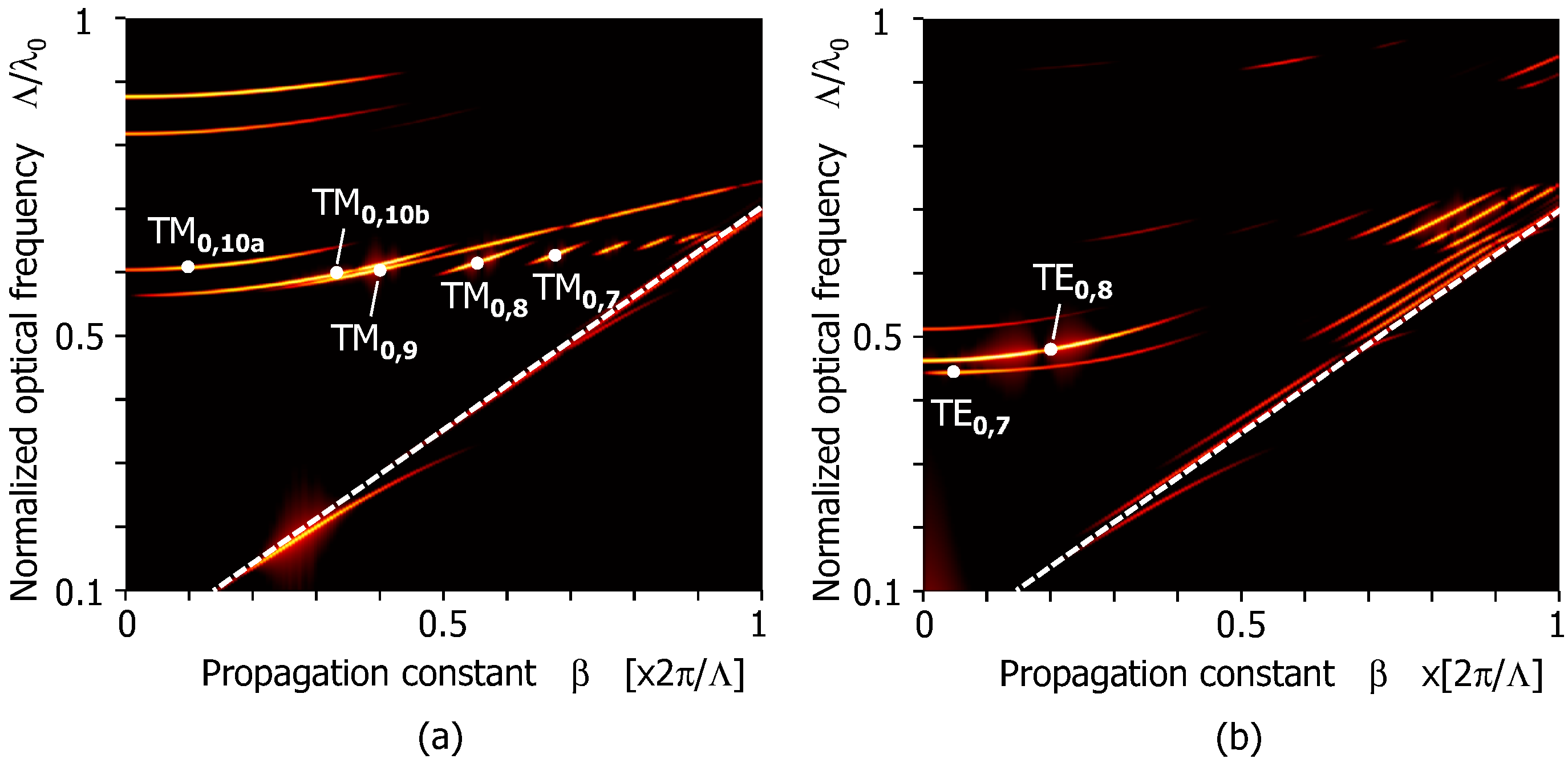
We repeated calculation of the spectra for various propagation constant (
β) as described in the last part of the previous section, and assembled them to a two-dimensional matrix (
β versus normalized optical frequency). A pseudo-color plot of the matrix for TM and TE modes are shown in
Figure 2. Bright lines indicate the confined (or long lifetime) modes. As can be seen from the figure, a discrete set of long-lifetime modes are supported. This is one of the most prominent characteristics of the RGM, and leads to the narrow-banded wavelength selective guiding function.
In
Figure 2, white broken lines running from the bottom to the right middle represent the light lines of the silica cladding. As we explained in [
16], in the presented fiber the light tends to hit the rod array with relatively large incident angle for GMR to occur. This is the reason why confined modes appeared far above the light lines. Comparing
Figure 2a,b, we notice that more number of modes appeared for TM modes (around wavenumber
). This is natural from the basic nature of GMR: the major E-field component of TM modes (
) lies parallel to the rods, feeling larger index modulation than the other (
). As a result of that, the bandwidth of GMR becomes wider for TM modes. According to our previous study, calculated losses of the TM modes of this type of structure were the order of 0.3 dB/cm for the operation wavelength of ∼1.6 µm [
16]. The major factor affecting the bending characteristics of these modes, and the critical bend diameter are both not clear at this time. All that we can say at present is, if the effective index distribution of the fiber is modified due to bending, the GMR resonance wavelengths of the inner and outer part of the curvature begin to diverge. If the divergence was smaller than the GMR bandwidth (Lorentzian function), ordinary radiation loss as conventional fibers would dominate. In contrast, if the bending is too acute, imperfect GMR reflection of the rods will become the main leakage path. The bandwidth of GMR depends on the index contrast of the rod/background, and was estimated as the order of 10 nm according to our previous study [
16].
Figure 2.
Dispersion relation of the sample fiber. (a) TM modes; (b) TE modes. White broken lines indicate the light lines of the cladding (n = 1.44).
Figure 2.
Dispersion relation of the sample fiber. (a) TM modes; (b) TE modes. White broken lines indicate the light lines of the cladding (n = 1.44).
Note that if we increase the diameter of the Si rods while keeping their pitch constant, the average index of the rod ring increases. This leads to the decrease of resonance wavelength of GMR. Therefore, dispersion curves tend to move downwards in this dispersion map.
Next, we tried to identify mode numbers.
Figure 3 shows the distribution of
of TM modes in
Figure 2a. All the fields were found to be concentric Bessel-functions in the center region. At the same time we also notice that, due to the GMR phenomena the field exhibited complicated distribution in the vicinity of the Si rods. Counting the number of peaks or nulls across the rods is therefore not straightforward. On the other hand, if we look at the field profiles on a cross section between the center of the fiber and the midpoint of adjacent rods (shown by a white radial line in
Figure 3a), fields are always smoothly varying, because the refractive index is uniform. An example field profile on the cross section is shown in
Figure 3f. As can be seen, we can easily count the number of peaks. Hereafter we define the radial mode number as the number of peaks of such profile. In
Figure 2 and
Figure 3a–e thus-defined mode numbers were indicated.
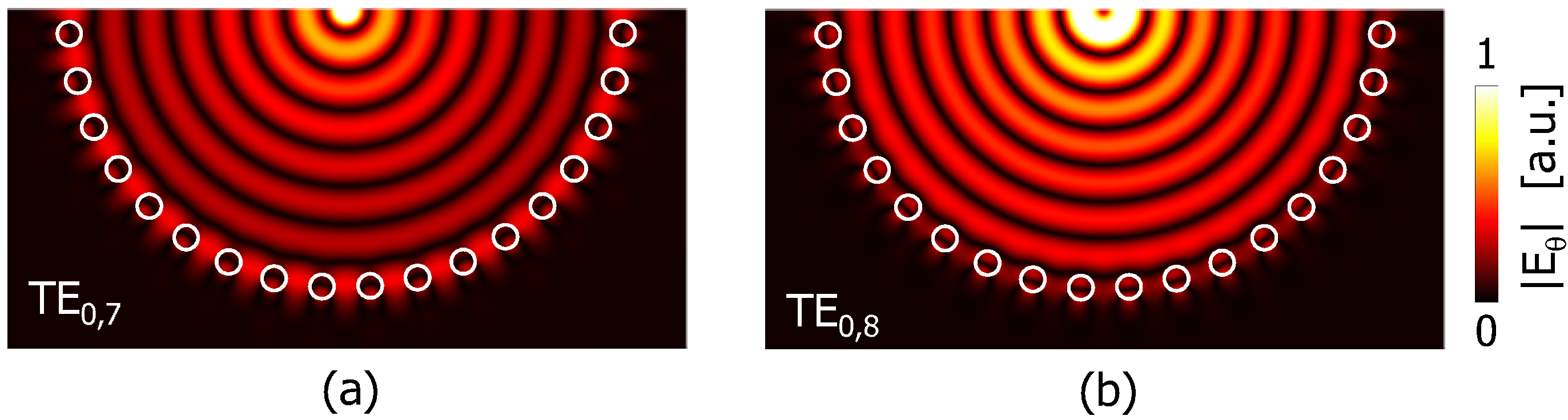
Figure 4 shows an example field profile of TE modes (
). Similar to TM, number of intensity peaks of
was countable and used as a mode number.
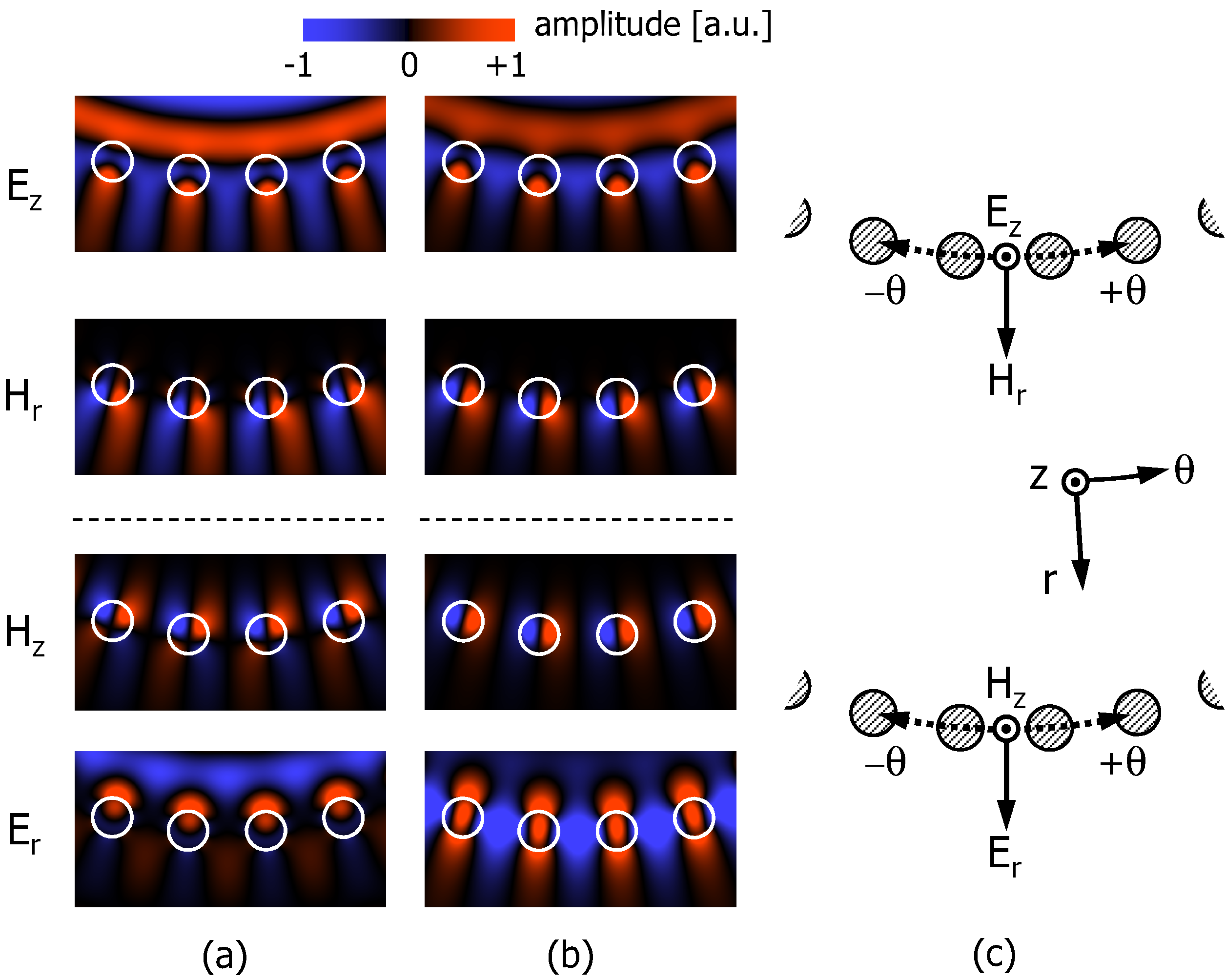
Interesting point is that there are apparently multiple modes which have the same radial mode numbers: TM
and TM
in
Figure 3. To investigate this we plotted a magnified view of amplitude profiles near the rods in
Figure 5. Here,
Figure 5a,b correspond to TM
and TM
, respectively.
Figure 5c denotes the relation between the rod and the field components. One may notice that the distribution looked almost the same for
and
, while obvious difference can be seen for
and
. This implies that different kind of leaky modes (modes localized in the vicinity of rods and propagating into
direction) are involved for the GMR to occur. We can interpret the origin of this “apparent duplicated mode number” as follows: the rod array acts as a reflective wall due to GMR. Roughly speaking, the radial mode number can be defined as a number of intensity peaks between the center of the fiber and the wall. However, there may appear multiple wavelengths where different kinds of GMR occur. As a result, multiple modes having the same radial mode number but different feature near the rods appear.
Figure 3.
Field profiles of the TM modes. (a) TM; (b) TM; (c) TM; (d) TM; (e) TM; (f) profile on a radial cross section of TM. The cross section is also indicated by a white line in (a). The radial mode number was defined as that of the peaks of .
Figure 3.
Field profiles of the TM modes. (a) TM; (b) TM; (c) TM; (d) TM; (e) TM; (f) profile on a radial cross section of TM. The cross section is also indicated by a white line in (a). The radial mode number was defined as that of the peaks of .
Figure 4.
Field profiles of the TE modes. (
a) TE
; (
b) TE
. See
Figure 2b for corresponding points.
Figure 4.
Field profiles of the TE modes. (
a) TE
; (
b) TE
. See
Figure 2b for corresponding points.
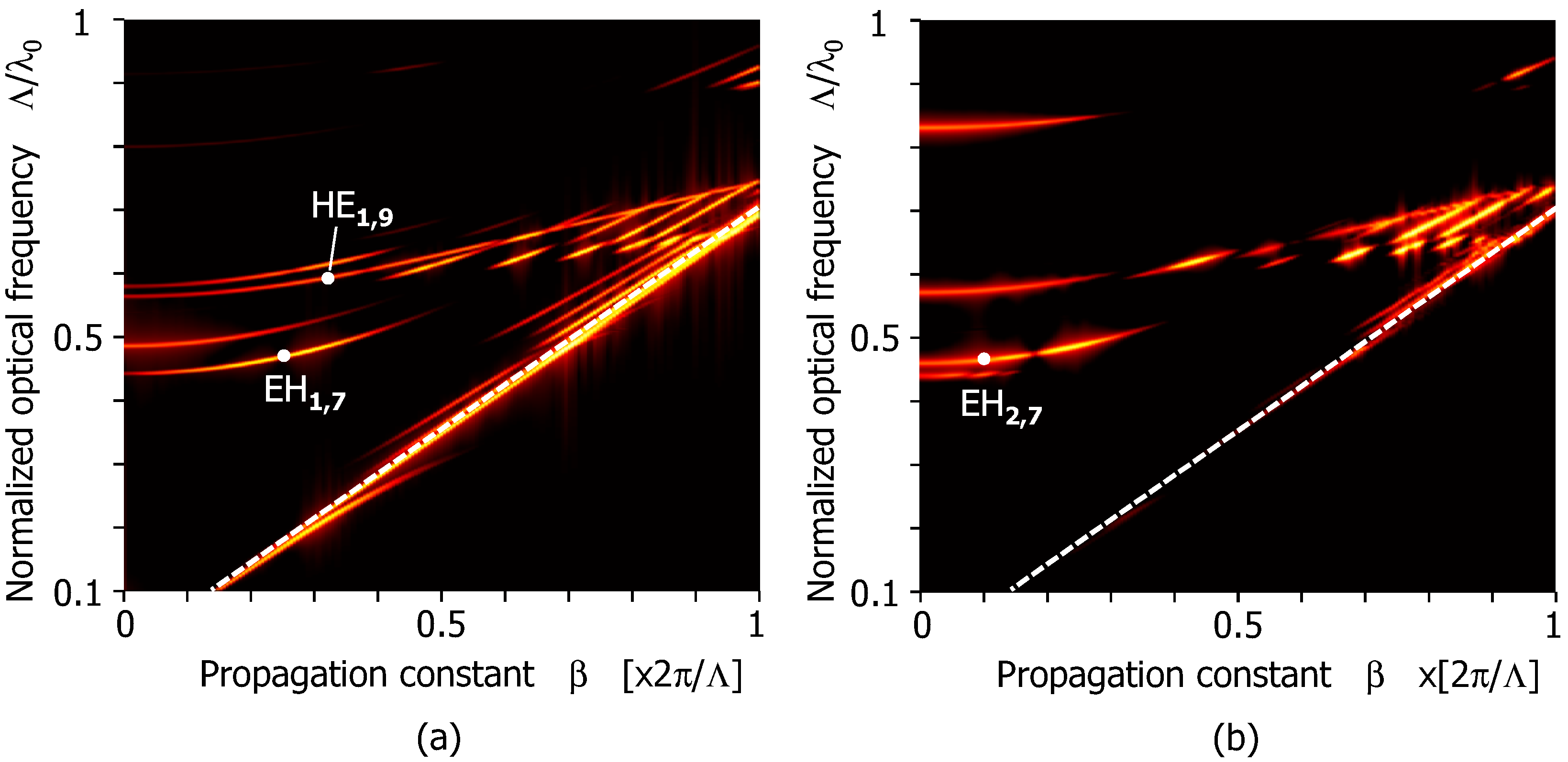
We also calculated hybrid modes that have non-zero azimuthal mode number (
m). Dispersion relations of
m = 1 ( EH
and HE
) and
m = 2 ( EH
and HE
) modes are displayed in
Figure 6a,b, respectively. In both figures there are mainly two frequency bands where confined modes exist:
and
. These ranges almost correspond to those of TM and TE modes shown in
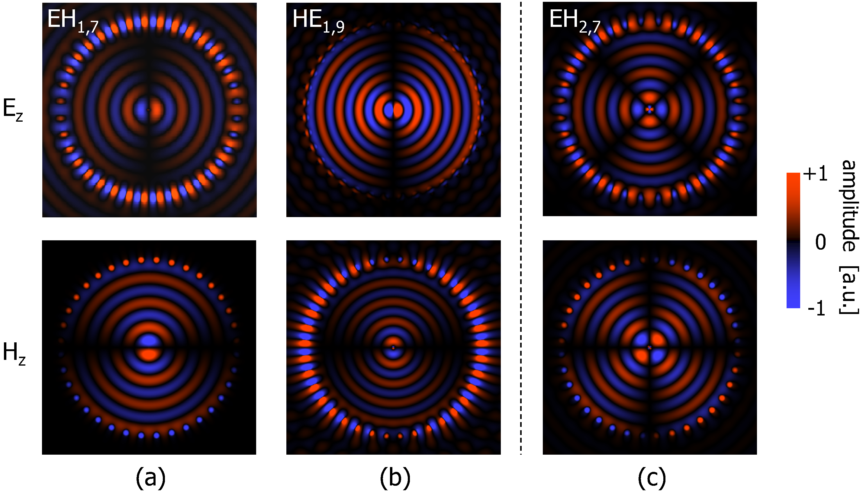
Figure 2. Constituent rays of hybrid modes with small azimuthal mode number have only a small azimuthal wavenumber: they hit the periodic rod array with almost the same angle as TM and TE modes. Thus the frequency bands of high reflectivity due to GMR become similar to TM and TE situations. This will be an explanation for the possible frequency bands for the hybrid modes. Field profiles of some of the EH and HE modes were also calculated. Results are displayed in
Figure 7. We confirmed that around the center part of the fiber, E- and H-fields behaved as the same manner as conventional circular fibers:
i.e.,
and
distributed with
[rad] spatial phase difference to each other. The rod array also represented 2
π (
m = 1) or 4
π (
m = 2) phase distribution over an entire rod circle along the azimuthal direction. This indicates that temporal or spatial phase difference between adjacent rods was not exactly 2
π, leading to a small degradation of reflectivity as a GMR wall [
23].
Figure 5.
Detailed field distributions of (
a) TM
and (
b) TM
. Locations on the dispersion curves are indicated in
Figure 2a. (
c) Relations between the rods and the field components.
Figure 5.
Detailed field distributions of (
a) TM
and (
b) TM
. Locations on the dispersion curves are indicated in
Figure 2a. (
c) Relations between the rods and the field components.
Figure 6.
Dispersion relations of the modes with non-zero azimuthal mode numbers. (a) EH and HE modes; (b) EH and HE modes.
Figure 6.
Dispersion relations of the modes with non-zero azimuthal mode numbers. (a) EH and HE modes; (b) EH and HE modes.
Figure 7.
Mode field profiles of EH and HE modes. (
a) EH
; (
b) HE
; and (
c) EH
. For detailed location on the dispersion relation, see
Figure 6.
Figure 7.
Mode field profiles of EH and HE modes. (
a) EH
; (
b) HE
; and (
c) EH
. For detailed location on the dispersion relation, see
Figure 6.


