1. Introduction
The explosive growth of both fixed and mobile data-centric traffic along with the inevitable trend towards all-IP/Ethernet transport protocols and packet switched networks will ultimately lead to an all-packet-based converged fixed mobile optical transport network from the core to the access network. To address the increasing capacity and speed requirements in the access networks, wavelength-division multiplexed (WDM) and/or coarse WDM (CWDM)-based passive optical networks (PONs) are expected to emerge as the next-generation optical access infrastructure. However, due to several techno-economic hurdles, CWDM-PONs are still considered an expensive solution and have not yet made any significant inroads into the current access area. One of the key technology hurdles is the scalability of the CWDM-based PONs. Passive component optical insertion losses limit the reach of the network or the number of served optical network units (ONUs). The CWDM standard from the International Telecommunication Union-Telecommunication Standardization body (ITU-T G.694.2) defines a maximum of 18 channels operating over the entire optical fiber communication spectrum from 1270 nm to 1610 nm (e.g., 340-nm bandwidth) with 20-nm channel spacing [
1]. In recent years, optically amplified CWDM approaches have emerged, and new designs of optical amplifiers have been proposed and demonstrated. The critical design parameter for these amplifiers is the very wide optical amplification bandwidth (e.g., 340 nm combined for both downstream (DS) and upstream (US) traffic directions).
Recently, a hybrid Semiconductor Optical Amplifier (SOA)-Raman amplifier was shown to be capable of providing a 150-nm bidirectional gain (e.g., 75 nm in each direction separately) over the PON’s downstream (1483–1557 nm) and upstream (1283–1357 nm) CWDM wavelength band with an 18 dB gain (<2 dB ripple) and 19.5 dB gain (1 dB ripple), respectively [
2,
3]. Other researchers have proposed and demonstrated alternative designs to achieve wide amplifier gain bandwidths. For example, Saito
et al., demonstrated a discrete Raman amplifier with 100-nm gain bandwidth over the full O-band, but at the expense of six pumps, to obtain an average gain of 10.5 dB with less than 1-dB variations [
4]. A fiber optical amplifier combining optical parametric and Raman processes was demonstrated by overlapping the parametric gain with pump-induced Raman gain in [
5]. This approach was mainly focused on the influence of the pump-induced Raman gain on a broadband fiber optical parametric amplifier (OPA), without focusing on the optimization of the two processes and has exhibited a very high gain ripple. It exhibited a 208-nm bandwidth and a gain in excess of 10 dB; however, a very high gain ripple of ~12 dB [
5] made it inappropriate for network-type applications; furthermore, the effect of the generation of multiple idler wavelengths from the parametric process was not addressed. Recently, we presented the results for a 170-nm bandwidth HROPA with <4 dB gain ripple and minimum gain of 20 dB using only three pumps operating only at the upper band (e.g., 1450 nm–1610 nm) of the CWDM wavelengths [
6,
7,
8].
In this paper, we extend our previous work to the lower half of the CDWM band (e.g., 1270 nm–1430 nm), which adds some challenges in the design. These challenges include the much wider operation frequency bandwidth of the hybrid Raman-OPA (HROPA) in the lower CWDM band compared to that of the upper CWDM band. In particular, although the wavelength range of the two bands (e.g., 1270 nm–1430 nm and 1450 nm–1610 nm) is the same (e.g., 160 nm), in the frequency domain, the lower CWDM band has a bandwidth of ~26 THz, whereas the upper CWDM band has ~20 THz. Hence, this much wider frequency bandwidth makes the selection of pump wavelengths and powers more challenging, in particular when high gain, low gain ripple and ultra-wide bandwidth is required. The OPA process is symmetric in the frequency domain, and hence, the parametric pump wavelengths, powers and fiber lengths must be chosen properly to cover this large bandwidth in the wavelength domain (which is not symmetric). In addition, to achieve minimum ripple, the Raman pump must be placed at a position in which the Raman gain compliments the OPA gain. In particular, its highest gain coincides with the dip in the OPA gain. However, the optimum Raman pump wavelength is required to be at 1270 nm, which is also the wavelength of the first CWDM channel. Hence, such a configuration generates strong in-band crosstalk for the first signal channel, and it is impossible to make the amplifier functional at this signal wavelength. Therefore, to overcome the aforementioned challenges, we modified our previous HROPA design and present a theoretical and simulation analysis of the HROPA performance. For the first time, to our knowledge, we show error-free performance at this entire bandwidth. The design of such an amplifier and its error-free performance operation will enable CWDM PONs.
The paper is structured as follows:
Section 2 presents the amplifier configuration and the mathematical model for the HROPA design. In
Section 3, we present the modeling results and discuss the design performance. Finally, in
Section 4, we summarize the outcome of the proposed configuration.
2. Amplifier Configuration
In [
8], we proposed and demonstrated the operation of the HROPA configuration for amplification of the top half of the CWDM band (e.g., 1450 nm to 1610 nm). We also described and implemented a method to overcome crosstalk issues related to the generation of idlers due to the parametric process. Since DS and US traffic in a CWDM PON counter propagate, we can separately amplify the two bands [
2,
3]. The same concept used for the implementation of the HROPA design in [
8] can be implemented to cover the lower half of the CWDM band (e.g., 1270 nm to 1430 nm), as shown in
Figure 1. However, as we will discuss later, there are some significant differences in the design that affect the HROPA performance and applicability of the previous design.
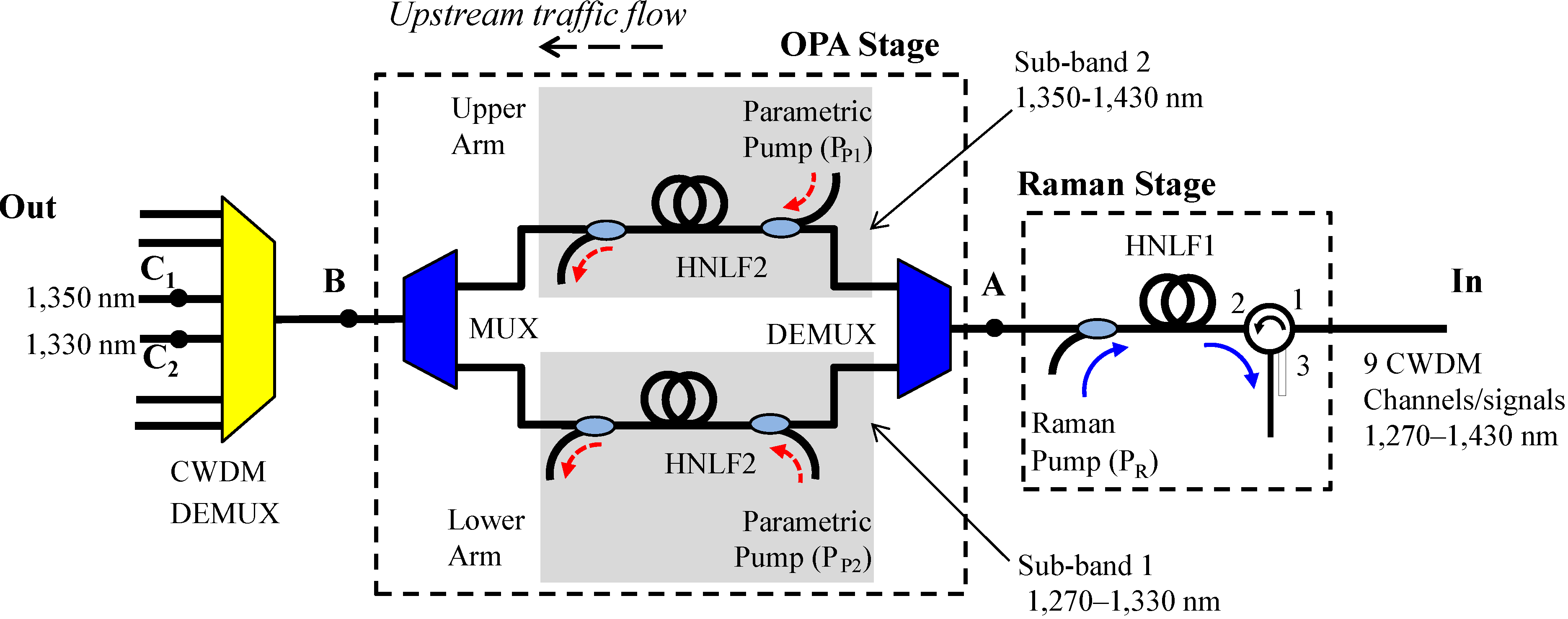
The HROPA consists of a Raman amplification stage followed by a parametric amplification stage (note that in
Figure 1, the signal propagates from right to left). The Raman and parametric processes are carried out separately in two different highly nonlinear fibers (HNLFs). The reason for this separation of the two processes is based on the fact that, on the one hand, the OPA process requires a short fiber length to achieve a wide gain bandwidth and, on the other hand, the Raman process requires a long fiber to achieve high gain. Hence decoupling the two processes allows for better optimization of the associated fiber lengths and pump optical powers and wavelengths. The Raman pump is placed such that the Raman peak gain is at the same wavelength range as the valley of the parametric gain curve. This allows us to compensate for the large gain ripple from the parametric process.
Since our ultimate goal is to use the proposed HROPA in a CWDM-based PON, we are interested in simultaneous transmission of signals at the CWDM wavelengths (e.g., US traffic) as defined by the standards [
1]. Therefore, we study the amplification of the nine nominal CWDM channels in the 1270 nm–1430 nm band as they propagate simultaneously through the proposed amplifier. A very important issue in optical parametric amplification schemes is the generation of idlers, which contribute to crosstalk in a WDM network. To overcome this limitation, we have proposed and demonstrated an optical parametric amplifier (OPA) stage within the HROPA, as shown in
Figure 1, which sufficiently suppresses the idlers [
8]. Similarly, for the O- and E-bands, we can split them into two wavelength sets, which are amplified separately (in two parallel paths). In particular, the US CWDM channels (e.g., 1270 nm–1430 nm), after the Raman amplification, are separated into two sub-bands with the use of a standard WDM demultiplexer (DEMUX). Band 1 consists of the first four CWDM channels (
i.e., 1270 nm, 1290 nm, 1310 nm and 1330 nm), which pass through the lower arm of the OPA section. Band 2 consists of the remaining five CWDM (
i.e., 1350 nm, 1370 nm, 1390 nm, 1410 nm and 1430 nm) channels, which pass through the upper arm. Each signal wavelength, through the OPA process, gives rise to an idler. Each idler is generated at a wavelength that is separated from the associated signal wavelength by an amount almost double the difference of the signal wavelength from the pump wavelength. In reality, the relation is defined in the frequency space by
ωi–
ωs=
2(
ωP–
ωs), where
ωi is the frequency of the idler,
ωs is the frequency of the signal and
ωP is the frequency of the parametric pump.
Figure 1.
Design of the hybrid Raman-optical parametric amplifier (HROPA) for upstream traffic. CWDM, coarse wavelength division multiplexer; DEMUX, demultiplexer; HNLF, highly nonlinear fiber.
Figure 1.
Design of the hybrid Raman-optical parametric amplifier (HROPA) for upstream traffic. CWDM, coarse wavelength division multiplexer; DEMUX, demultiplexer; HNLF, highly nonlinear fiber.
Hence, the first half of the CWDM signal wavelengths within Sub-band 1 (e.g., 1270 nm to 1330 nm) generate idlers that are in the wavelength range of 1344 nm–1418 nm (e.g., within Sub-band 2) or, in other words, at wavelengths higher than the parametric pump wavelength (e.g., 1340.2 nm). The second half of the CWDM signal wavelengths within Sub-band 2 (e.g., 1,350 nm to 1430 nm) generate idlers that are at wavelengths lower than the pump wavelength and fall within Sub-band 1 (e.g., 1256 nm–1336 nm). In each arm of the OPA section of the HROPA, the parametric pump must be filtered out by an appropriate DWDM filter (e.g., 25 GHz DWDM fiber Bragg grating (FBG) filter [
9]). The two sub-bands are then recombined using a WDM multiplexer (MUX) [
10]. Note that since the idlers generated at each sub-band fall outside the pass band of the associated WDM MUX port, the idler wavelengths are suppressed. The amplified CWDM PON channels are separated by a CWDM filter, as is required in any CWDM PONs. Each port of the CWDM DEMUX has a filter transfer function with a bandwidth of 23 nm at –30 dB [
11]. Finally, each wavelength is routed to the desired ONU through the appropriate optical path [
4].
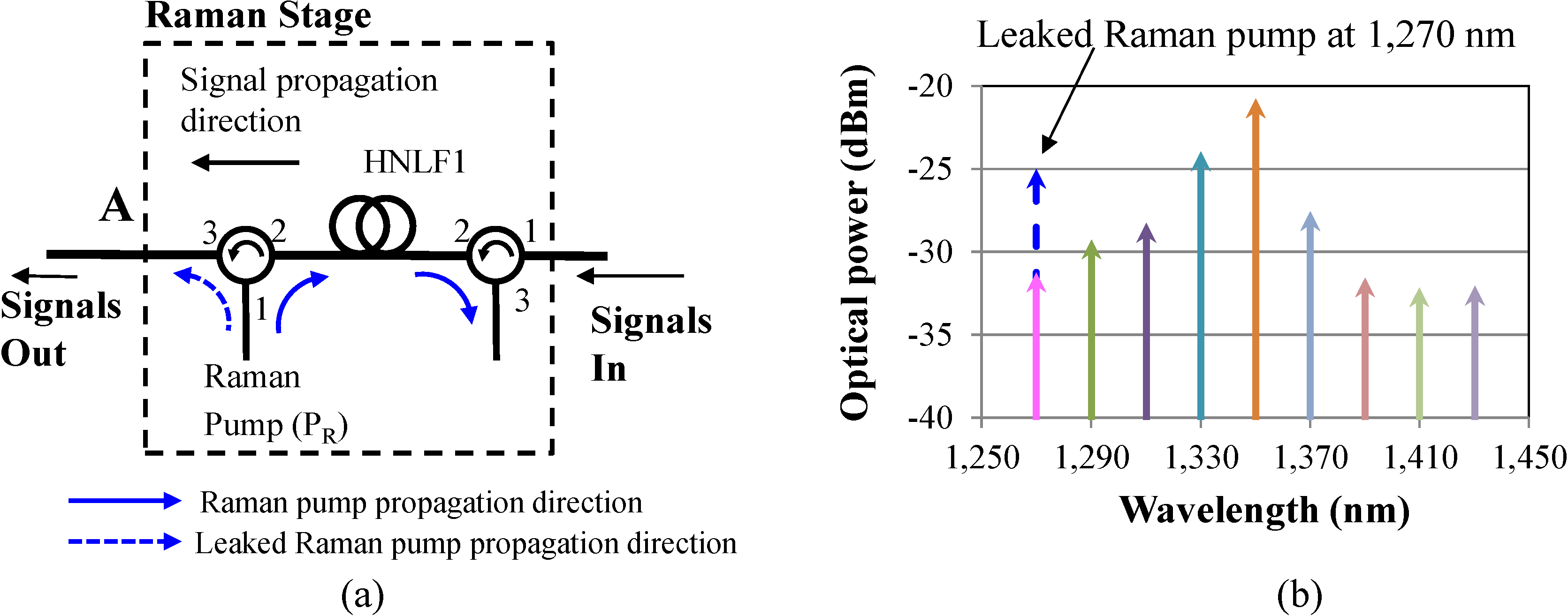
In the above description, we did not provide any specifics on the pump wavelength and power selection to achieve low ripple wide bandwidth amplification. To address the wide band amplification, a pump wavelength at 1340.2 nm is required for the OPA process. Furthermore, in order to achieve a ripple of <5 dB, the Raman pump must be placed at ~1270 nm. However, a 1270-nm Raman pump overlaps with the 1270-nm signal (first channel band) of the US traffic. Hence, in this case, a WDM coupler cannot be used as in
Figure 1 to couple the Raman pump to the HNLF. To overcome this limitation, a potential solution is the use of an optical circulator, which can couple the Raman pump in the HNLF and, through counter-propagation through the HNLF, achieve the desired signal amplification (
Figure 2). In
Figure 2a, we show only the modified Raman stage. The OPA stage is the same as the one described earlier (
Figure 1) and is not shown. Nevertheless, due to the high optical power (e.g., ~1 W) of the Raman pump and the non-ideal circulator isolation performance (e.g., 55 dB), a portion of the original Raman pump leaks through the circulator port (Port 1 to Port 3 leakage) and co-propagates with the CDWM signals (
Figure 2). Since the pump optical power is ~1 W, the leaked optical power through the circulator is at similar or even higher optical power levels as the first CWDM signal at 1270 nm (
Figure 2b). Thus, the leaked Raman pump causes significant crosstalk issues at the receiver and significantly deteriorates the signal performance. Using a single pump at a lower or higher wavelength than 1270 nm is not an effective and viable solution either, because although it overcomes the crosstalk issue, it generates a very high ripple (e.g., >7 dB) that can be detrimental to the signal performance.
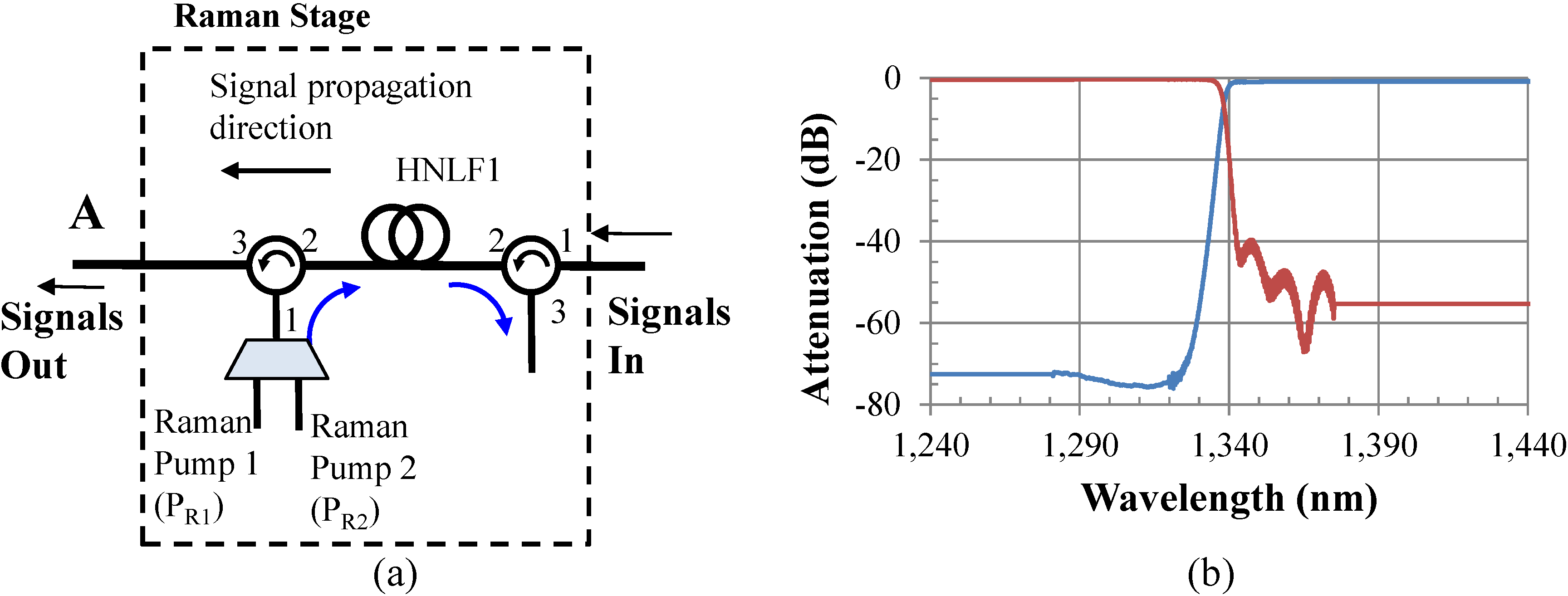
To overcome both the crosstalk issue, as well as the high ripple performance, an alternative and viable approach is to use two Raman pumps as shown in
Figure 3a. The first one (P
R1) is at 1260 nm, and the second one (P
R2) is at 1280 nm, with powers of 1.1 W and 0.63 W, respectively. Since these two pumps are 10 nm apart from the first two CWDM channels, 1270 nm and 1290 nm, crosstalk at the receivers is not an issue, as it is suppressed significantly through the optical filters used in the HROPA for the recombination and splitting of bands and/or channels. The WDM MUX/DEMUX filter transfer function used in the HROPA is shown in
Figure 3b, and it is typical in WDM network designs. The use of two Raman pump wavelengths at 1260 nm and 1280 nm, is equivalent to a single Raman pump at 1270 nm at higher optical power.
Figure 2.
(a) The modified Raman section of the HROPA that uses a single Raman pump and an optical circulator to couple the Raman pump in the HNLF; (b) optical spectrum at point A after the Raman amplification when the Raman pump is at 1270 nm, which highlights the problem of having the signal and leaked pump at the same wavelength.
Figure 3.
(a) Upstream HROPA with two Raman pumps; (b) measured DEMUX/MUX transfer function.
Figure 3.
(a) Upstream HROPA with two Raman pumps; (b) measured DEMUX/MUX transfer function.
To model the HROPA, we used the well-known Raman and parametric equations with the goal of achieving a bandwidth of 170 nm with a minimum ripple. We separate the HROPA model into two sets of equations. The first one describes the Raman pump process, which takes place in HNLF1. For a multiple pump scheme, variations in the
i-th Raman pump (
PRi) and signal (
Ps) powers along the amplifier length can be described by the following wave equations [
12,
13].
where
i = 1, 2, 3…
N and total
N represents the number of Raman pumps.
j (= 1, 2, …,
i – 2,
i – 1) and
k (=
i + 1,
i + 2, …,
N) represent the Raman pumps, such that
λRj <
λRi <
λRk. The corresponding Raman gain coefficients are
gRji,
gRik and
gsi, and
ωRi,
ωRk and
ωs are the angular frequencies of the Raman pumps and the signal, respectively. Equation (1) describes the optical power evolution of the
i-th Raman pump. In particular, the first term in Equation (1) shows the power flow to the
i-th Raman pump from the Raman pumps with a smaller wavelength, e.g., the
j-th Raman pump. The second term describes the power transfer from the
i-th Raman pump to the Raman pumps with a higher wavelength, e.g., the
k-th Raman pump. Finally, the third term of Equation (1) describes the power transfer from the
i-th Raman pump to the signal, and the last term represents the fiber attenuation. Equation (2) describes the evolution of the signal optical power as it propagates through the Raman amplifier section.
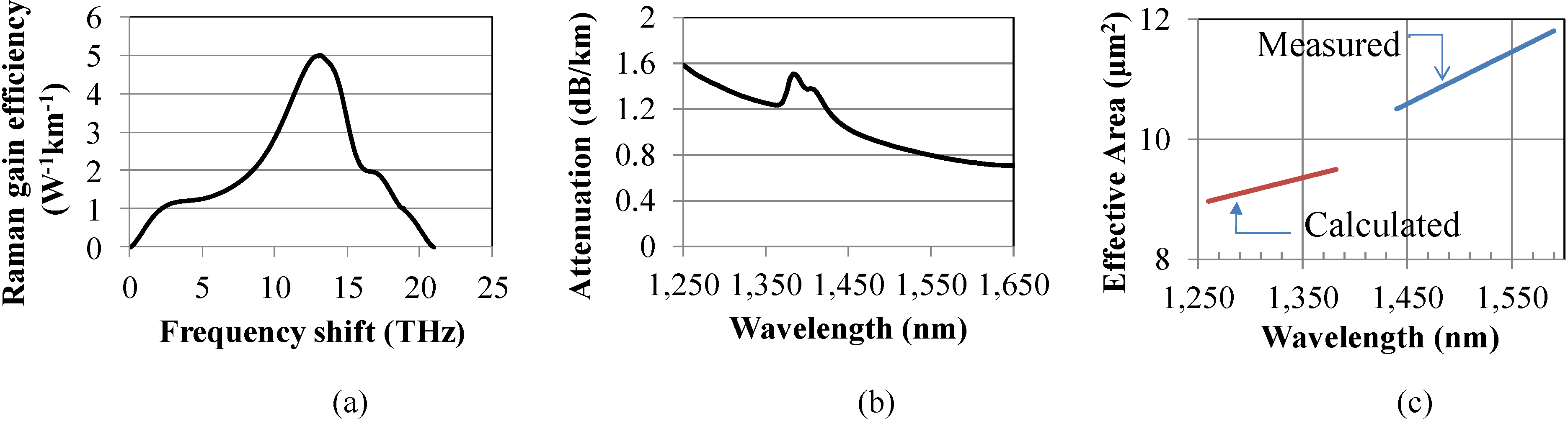
It is known that the Raman gain efficiency increases as the pump wavelength decreases. Therefore, one must obtain the corresponding Raman gain coefficient when designing a broadband amplifier that includes Raman pumps covering a very wide range of wavelengths. As described in [
12,
13,
14], we can scale the Raman gain coefficient from measurements made at one pump wavelength
λP to a new pump wavelength
λP-new as follows:
where,
Here,
gR(
Δν,
λP) is the measured Raman gain coefficient at a pump wavelength
λP,
Aeff is the effective area of the fiber provided as a function of the wavelength and
Δν is the frequency separation between the pump and the signal. Therefore, to model the HROPA accurately, we followed this analysis and generate the corresponding Raman gain efficiencies using Equations (3)–(4) and the numerical data shown in
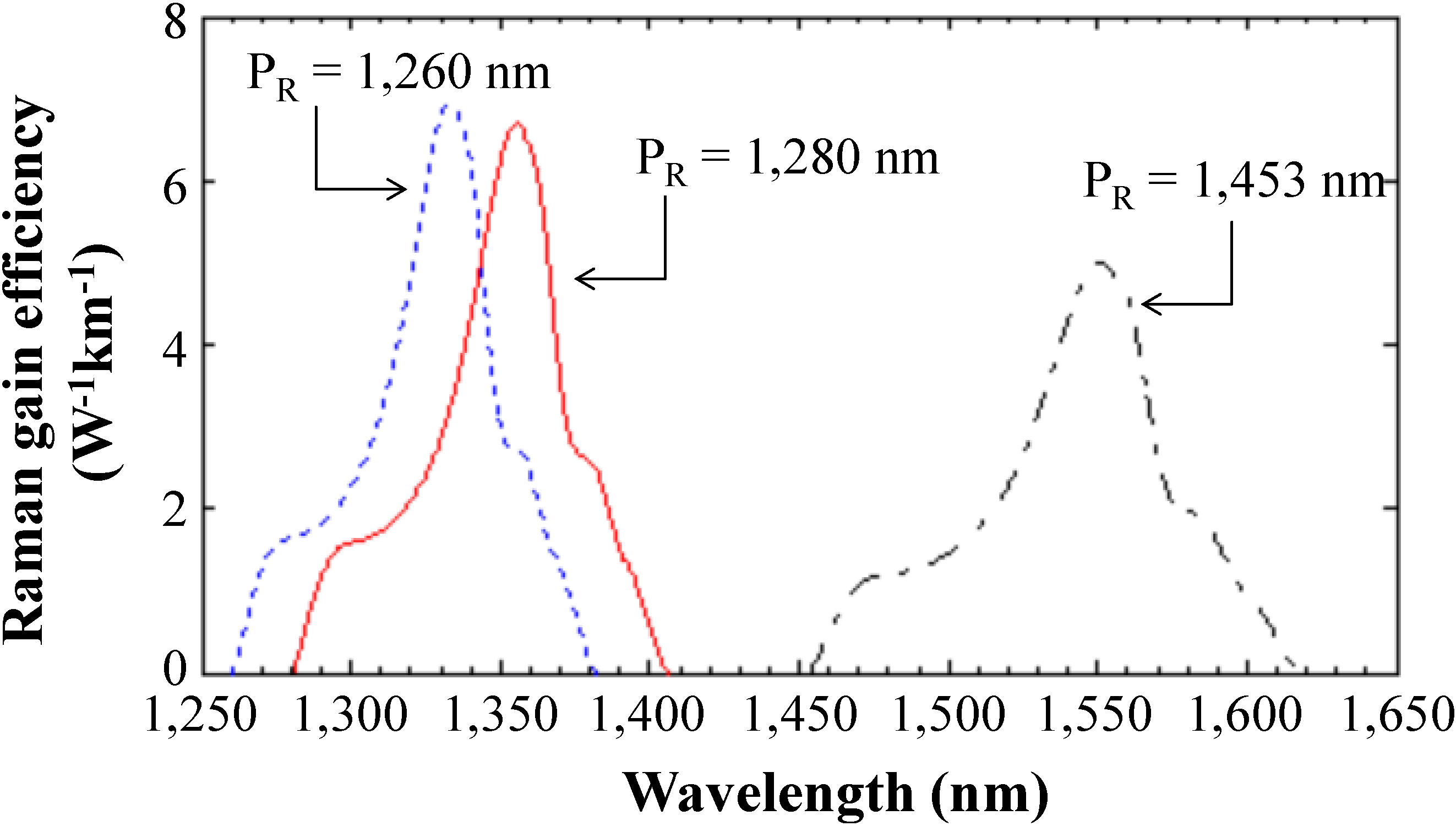
Figure 4a,c [
15]. The calculated Raman gain efficiencies for the two Raman pumps at 1260 nm and 1280 nm are shown in
Figure 5 along with the measured Raman gain efficiency at 1453 nm. Note that the Raman gain efficiency increases as the pump wavelength decreases [
12,
13,
14], and it helps to overcome the high optical fiber attenuation at the bandwidth of interest (
Figure 4b). We used these derived Raman gain efficiencies in our theoretical performance evaluation of the proposed HROPA.
Figure 4.
High non-linear fiber measured parameters [
15]. (
a) Raman gain efficiency; (
b) fiber attenuation; (
c) effective area as a function of wavelength.
Figure 4.
High non-linear fiber measured parameters [
15]. (
a) Raman gain efficiency; (
b) fiber attenuation; (
c) effective area as a function of wavelength.
Figure 5.
Derived Raman gain efficiency at 1260 nm and 1280 nm from the measured Raman gain efficiency of 1453 nm.
Figure 5.
Derived Raman gain efficiency at 1260 nm and 1280 nm from the measured Raman gain efficiency of 1453 nm.
In HNLF2, we have the OPA process. Considering a single-pump OPA, the four wave mixing (FWM) equations for the parametric pump (
Pp), signal (
Ps) and idler (
Pi) are expressed by Equations (5)–(9) [
16].
where
γ is the fiber nonlinearity coefficient and
Δβ is the linear phase mismatch.
ωP,
ωs are the pump and signal frequencies, and
ωo is the fiber zero dispersion frequency. Here,
φ(
z) describes the relative phase difference between the four involved light waves [
16]. The linear phase mismatch
Δβ is related to the fiber third- and fourth-order dispersion parameters
β3 and
β4, as in Equation (7) [
7,
17]. Note that the inclusion of the fourth-order dispersion parameters
β4 is very important, as its omission may lead to either overestimation or underestimation of the gain bandwidth [
7].
In our model, we have assumed that the state of polarization (SOP) on the incoming signals and pumps are aligned. In a real system, this may not be always true. Hence, this may cause polarization-dependent gain (PDG) for the amplifier. However, polarization diversity techniques (PDTs) can minimize the PDG. For example, in [
18] a single-pump OPA achieved gain independent of the signal SOP using PDT. In this approach, the pump and the signals are launched into a polarization beam splitter (PBS), before entering the HNLF. The incoming signals are split into their two orthogonal polarizations. The transmission and reflection port of the PBS are connected in a closed loop to the optical fiber. A polarization controller (PC) within the loop is used to adjust the SOP of the pump. The two orthogonal polarization components are recombined through the PBS and exit the amplifier. This PDT was also used in a field-trial evaluation of an OPA configured as an in-line amplifier [
19]. The field trial demonstrated that the PDT can reduce PDG to as low as ~0.04 dB. A polarization-independent Raman-assisted OPA (for OPA gain enhancement) using both depolarized Raman and parametric pumps has also been demonstrated with a PDG of <1 dB [
20]. Hence, similar approaches can be used in our proposed HROPA design.
3. Performance Evaluation-Simulation Results
To evaluate the HROPA performance, we use a two-step modeling and simulation methodology. First, we implement a MATLAB-based model of the equations described in
Section 2 to calculate the best choices of OPA and Raman pump powers and wavelengths. In particular, first, we perform parametric runs for the OPA pump wavelength to achieve the optimum gain bandwidth. Then, we perform parametric runs to optimize the OPA pump power. Following that, we evaluate the optical power of the Raman pumps that will minimize gain ripple.
The HNLF parameters that we used in our simulation are
λo = 1340 nm,
γ = 11.67 W
−1/km,
β3 = 0.049 ps
3/km and
β4 = 2.35 × 10
−6 ps
4/km [
15]. In our simulation, we consider the small signal regime (e.g., ≤ –28 dBm), and we ignore the signal to signal interactions. The model takes into account the insertion losses of the different passive components and the fiber, as well as the filters’ transfer functions. The OPA pump wavelength at 1340.2 nm and the HNLF length
Lp = 150 m for HNLF2 were selected, such that we cover the gain bandwidth of 170 nm (1264 nm–1436 nm). We find that the optimum OPA pump powers are
PP1 = 2.52 W (upper band) and
PP2 = 2.3 W (lower band) to achieve the target gain of 20 dB. The Raman pump powers of
PR1 = 1.1 W at 1260 nm and
PR2 = 0.63 W at 1280 nm were selected with
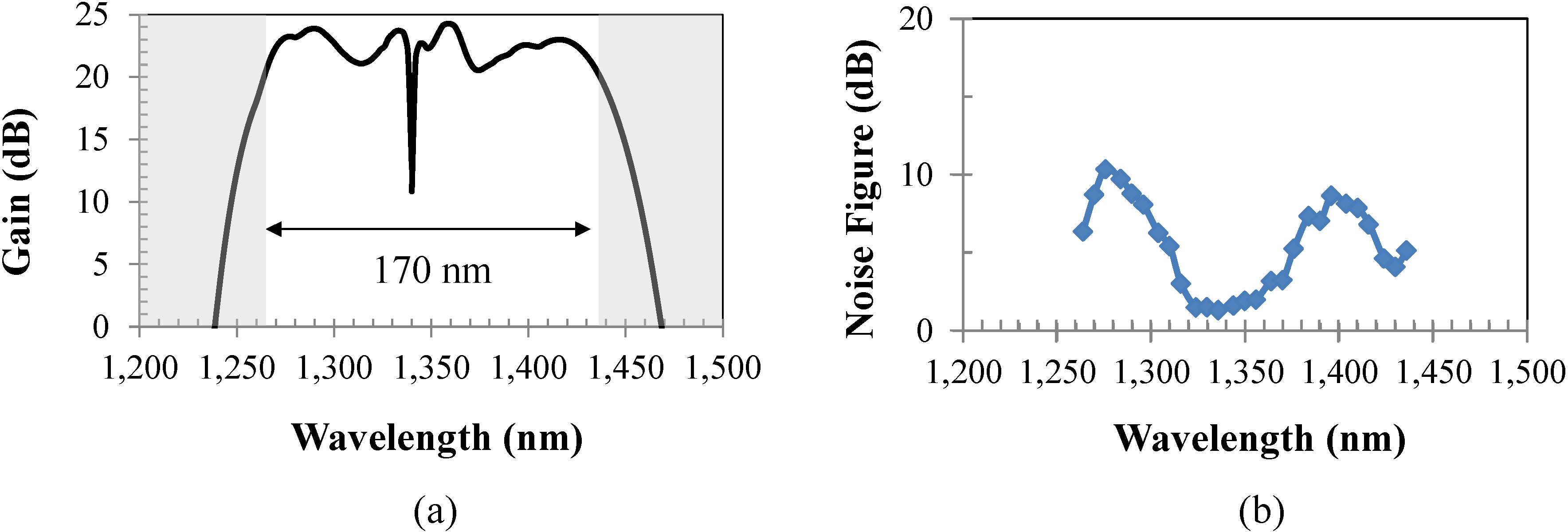
LR = 500 m for HNLF1 to obtain a minimum ripple. We obtained a signal gain of ≥20 dB and a gain ripple of <4 dB using the aforementioned parameters, as shown in
Figure 6a. The dip in the spectrum is due to the filtering of the OPA pump wavelength.
The second step of our methodology is performed using the simulation tool, Synopsis RSoft, where we build a simulation model of the HROPA design with the selected wavelength and optical pump powers from the first step. The simulations performed in Synopsis RSoft include all possible degrading effects in the system (e.g., fiber dispersion, fiber attenuation, stimulated Brillouin scattering (SBS), Rayleigh backscattering, interchannel and intrachannel crosstalk and amplified spontaneous emission noise). We obtained the noise figure (NF) using Synopsis RSoft, shown in
Figure 6b. As can be seen in
Figure 6b, the NF ranges from 1.5 to 11.5 dB. Since the center of the band is Raman amplification dominated, the NF is lower than in the edges, where the noise figure is OPA dominated.
As we described in
Section 2, the splitting and combining of the two bands is achieved using standard WDM DEMUX and MUX components. Hence, due to their non-ideal band-to-band or channel-to-channel isolation, crosstalk terms may be present in the system. There are two types of crosstalk terms that may propagate through the system and can end up at the receiver and, hence, affect the amplifier performance. The first one is due to the non-ideal performance of the WDM DEMUX, which allows for some leakage of the upper-band signals to the lower arms and
vice versa. The second set of crosstalk terms is due to the generation of the idlers at the OPA sections and their leakage through the WDM MUX. Note that these crosstalk terms may be further suppressed by the CWDM DEMUX that routes the signals to the desired path. However, the degree of crosstalk suppression depends on the relative difference of the crosstalk wavelengths to the pass band of the CWDM DEMUX. To further understand the potential limitation posed by the presence of the crosstalk terms and their impact on the performance of the HROPA, we present a worst-case scenario analysis and characterize the impact on the amplifier performance.
Figure 6.
(a) Available signal gain of the 170-nm bandwidth for the given fiber parameters and selection of pump optical powers and wavelengths; (b) noise figure (NF) performance.
Figure 6.
(a) Available signal gain of the 170-nm bandwidth for the given fiber parameters and selection of pump optical powers and wavelengths; (b) noise figure (NF) performance.
We define the signals, idlers, and leakage terms as:
Signals:
SU: upper-band signals,
SL: lower-band signals.
Leakage:
LU: leaked upper-band signals to the lower section,
LL: leaked lower-band signals to the upper section.
Idlers from leakage:
iLU: idlers generated from leaked upper-band signals in the lower section,
iLL: idlers generated from leaked lower-band signals in the upper section.
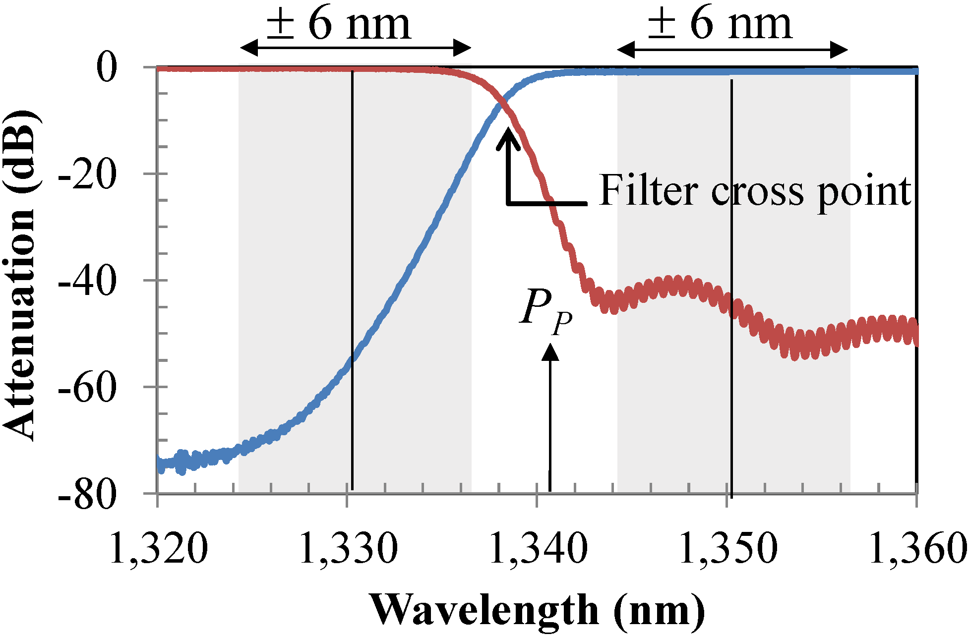
We focus on the two CWDM channels that are at the edges of the two bands (e.g., 1330 nm and 1350 nm). These two wavelengths represent the two worst-case scenarios, since they are closer to the OPA pump wavelength and at the roll-off of the filter transfer functions. Hence, they and their associated crosstalk terms experience the least suppression through the filters. The other channels experience isolation of >40 dB, and hence, they do not significantly contribute to any signal deterioration within the system. We must note here that in a CWDM system, the wavelength channel is defined within a ±6 nm bandwidth [
1].
Figure 7 shows the placement of 1330 nm and 1350 nm signals under the filter transfer function with their allowable bandwidth of ±6 nm (shaded area). Therefore, the effect of the generated crosstalk terms (e.g., idlers and leakage) strongly depends on the actual transmitter wavelength. We investigate the effect of simultaneous transmitter wavelength misalignment from the ITU defined center channel of 1330 nm and 1350 nm in the generation of crosstalk terms and the impact on the design of the HROPA. This misalignment can be up to 6 nm on either side of the designed center wavelength of the signal band [
1]. We identify the worst case scenario as the one with
SU at 1344 nm and
SL at 1336 nm.
Figure 7.
The possible wavelength position of the 1330 nm (±6 nm) and 1350 nm (±6 nm) channels under the filter transfer function (PP OPA pump).
Figure 7.
The possible wavelength position of the 1330 nm (±6 nm) and 1350 nm (±6 nm) channels under the filter transfer function (PP OPA pump).
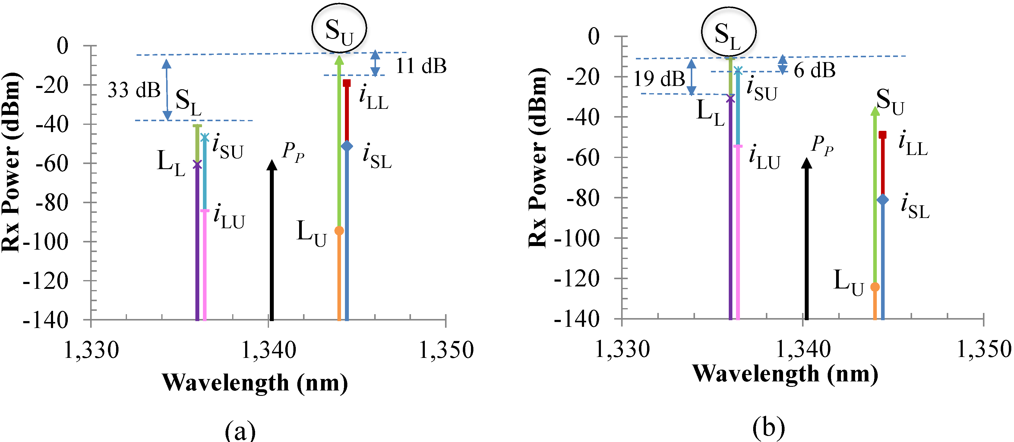
Figure 8.
Amplified signals and crosstalk terms after the CWDM (a) at point C1 or the 1350-nm port, with a worst-case crosstalk of −11 dB from iLL, and (b) at point C2 or the 1330-nm port, with a worst case crosstalk of −6 dB from iSU.
Figure 8.
Amplified signals and crosstalk terms after the CWDM (a) at point C1 or the 1350-nm port, with a worst-case crosstalk of −11 dB from iLL, and (b) at point C2 or the 1330-nm port, with a worst case crosstalk of −6 dB from iSU.
Figure 8 shows all of the signals and crosstalk terms for the above worst-case scenario at point C
1 and C
2 of the HROPA. Points C
1 and C
2 are defined in
Figure 1 and correspond to the 1350-nm port and 1330-nm port of the CWDM, respectively. As can be seen in
Figure 8a, the main crosstalk term on the
Su channel (1344 nm) is
iLL (the idler generated from the leaked lower band signal at 1336 nm in the upper arm of the OPA section), and its crosstalk is ~−11 dB. Similarly, at point C
2, the highest crosstalk term on
SL channel (1336 nm) is
iSU (~−6 dB), as shown in
Figure 8b. In the first case, the crosstalk term
iLL is under the pass band of the WDM MUX, whereas in the second case, the
iSU is under the roll-off of the filter transfer function, and hence, they are not filtered out or suppressed enough as they pass through the WDM MUX. Crosstalk terms at the other wavelengths do not contribute to the signal degradation, because they are suppressed by the filters and have much lower optical power.
Using the Synopsis RSoft simulation tool, we evaluated the bit error rate (BER) performance for the above worst-case scenarios for standard non-return-to-zero (NRZ) 10-Gbps signals. The receiver was calibrated for a BER of 10−12 at a received optical power of −28.5 dBm. The highest crosstalk term iSU at −6 dB affects the BER performance significantly, giving a BER of >10−2 at the 1330-nm port.
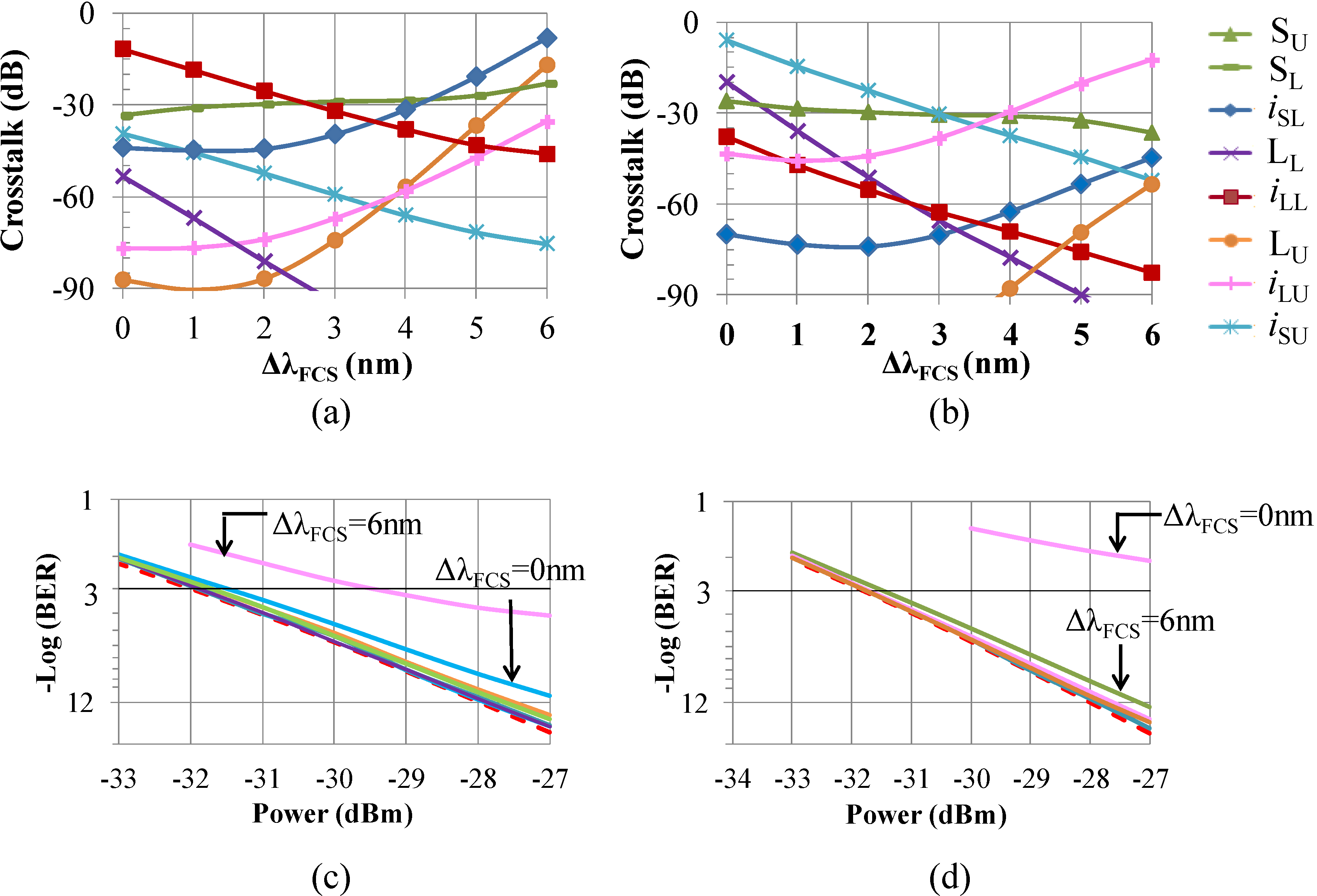
Figure 9.
Crosstalk on: (a) SU = 1344 nm at point C1; (b) SL = 1336 nm at point C2 as a function of WDM MUX filter cross point shift (ΔλFCS); BER at 10 Gbps non-return-to-zero (NRZ) of (c) SU = 1344 nm at point C1; and (d) SL = 1336 nm at point C2 (note: crosstalk terms <−90 dB are under the noise floor).
To improve the amplifier performance so that it can be utilized in a PON requires further suppression of the crosstalk terms. This suppression of the crosstalk terms can be achieved by engineering the WDM MUX and, in particular, the filter cross-point position. Therefore, we performed a study in which we investigated the impact of the idler/crosstalk effect and the filter transfer function interaction on the BER signal performance. The results are shown in
Figure 9 for the two worst-case scenarios mentioned above.
Figure 9a shows all crosstalk terms present at point C
1 as a function of filter cross-point shift (Δ
λFCS). We define the filter cross-point as the point of intersection of the two filter transfer functions of
Figure 7. Hence, the filter cross-point shift is the relative shift of the filter cross-point of the new filter from the original filter cross-point of 1337.2 nm used in
Figure 8, obtained by measurements of the filter in our lab. The crosstalk terms at point C
2 are shown in
Figure 9b. It is clear that for 1 nm ≤ Δ
λFCS ≤ 5 nm, all of the crosstalk terms are below −15 dB for both cases, and hence, now, the BER degradation due to the crosstalk terms is negligible, as can be seen in
Figure 9c,d.
Our analysis shows that with the proper design of the filters (and their associated filter transfer function), as well as the proper selection of pump wavelengths and powers, the O- and E-band HROPA can achieve error free performance for the entire band and for all possible transmitter wavelengths within the CWDM channel band, as defined by the ITU standards [
1]. The HROPA is based on separating the two amplification processes, e.g., Raman and OPA, so that we can optimize each one separately, because the OPA requires a short fiber length to achieve a wider gain bandwidth, whereas the Raman process requires a long fiber length to achieve high gain. Note that current technology allows us to design and fabricate WDM filters with a filter cross-point within ±1 nm from the desired wavelength, as required based on our analysis.


