1. Introduction
The new fourth-generation light-sources named free electron lasers (FEL), with the creation of coherent ultra-short, high-intensity, extreme ultra-violet (EUV) and soft X-rays pulses, represents a novel and extremely promising tool for the study of ultrafast dynamics in matter at atomic and molecular scales. Since the first ideas, more than 30 years ago, incredible progress, from an experimental and theoretical point of view, has been made in the development of these novel light sources [
1,
2,
3,
4,
5,
6]. In the last few years, large scale facilities have been built up producing ultrashort EUV/soft X-rays pulses, based on Self Amplified Stimulated Emission (SASE) scheme [
7,
8,
9]. This approach allows us to achieve a very high photons flux, but it is limited in the longitudinal coherence and energy stability. When the last two aspects are mandatory, a more complicated scheme has to be adopted, based on the use of a seed laser in the FEL pulses production process. So far, FERMI [
10] is the only existing seeded FEL around the world, whose characteristics in terms of longitudinal coherence, wavelength tunability and polarization variation make this machine a unique source for very accurate spectroscopic techniques.
Among all the possible spectroscopies, four wave mixing (FWM) experiments represent an extremely powerful and exiting approach to investigate the properties of matter. Up to now, only laser based FWM experiments were possible, because of the strong longitudinal coherence demanded in such kind of experiments. The typical features of SASE FEL are unluckily not able to satisfy the above conditions, which are, conversely, completely fulfilled by the FERMI parameters. FWM techniques are a particular class of non linear optics experiments, where two or three wavelengths are mixed together, producing an extra wavelength. In the more complex scheme, three different laser beams are temporally and spatially overlapped on the sample, generating a fourth scattered beam. The scanning of the time delay of one beam (probe) with respect to the other two incoming beams (pumps) reflects in a modulation of the intensity of the fourth beam (signal), correlated to the temporal dynamics of the modes excited into the sample. The phase matching between the three beams has to be satisfied with strong precision, so requiring a well defined and stable condition of the incoming fields. The large versatility of these techniques allows us to study very different scientific cases, from disordered systems [
11,
12] to spin dynamics [
13], from surface plasmon polaritons [
14] to nanotubes [
15].
Transient Grating (TG) [
16,
17,
18,
19] is a FWM technique for which it would be extremely interesting to extend its spectral range from visible to EUV region. The use of shorter wavelengths will allow the covering of a completely new length scale, fundamental for answering to many opened questions on liquids and glassy materials, such as the origin of thermodynamic properties [
20] and the anomalous acoustic attenuation mechanism [
21]. For this reason, a new EUV TG beam-line (TIMER) [
22,
23] will be soon available at FERMI. In details, the mesoscopic range (10 − 100
nm) will be fully covered for the first time, trying to shed light on extensively debated questions regarding the collective dynamics in disordered systems. Because the proposed wavelengths range is still uncovered by any existing technique, TIMER will be a very unique beam-line dedicated to the study of complex systems at mesoscopic length scales.
The TG extension to the EUV range requires many experimental improvements. The first issue is the impossibility to have efficient transmission optical elements working in the proposed range, thus all the typical solutions used in table-top TG schemes cannot be implemented as they are, but must be thoughtfully reconceived, resulting in a quite complex new optical scheme. Due to the complexity of TIMER, a critical test of all the possible experimental solutions has to be performed. In this paper, we propose a “step-by-step” evolution of the TG experimental setup, from table-top to FEL-based scheme, where all the possible solutions for TIMER realization have been taken into account.
In details, a new way to split and recombine two EUV pulses has been proposed, based on “mirror edge” beam splitters, which allows us to overcome the absence of effective transmissive beam splitters in the EUV region. Moreover, a simple scheme to perform TG experiment at large angle was implemented, which allows us to understand the possible problems for the future TIMER beam line, but also really useful for classical TG experiment, guaranteed a simple and fast way to change the accessible wave vector region of TG scheme. The application of the proposed solutions has been implemented in the realization of the first EUV TG setup. The test of this scheme on a glassy sample, and the comparison with the results obtained with classical TG schemes, are also reported.
2. Experimental Section
TG is a well established technique, particularly suitable for the study of standard and glass-former liquids. The general scheme is reported in
Figure 1.
Figure 1.
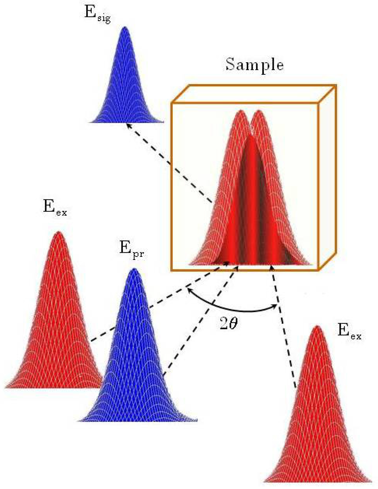
Schematic sketch of the Transient Grating (TG) experiment. Eex: pumps; Epr: probe; Esig: signal; 2θ: angle between pump pulses.
Figure 1.
Schematic sketch of the Transient Grating (TG) experiment. Eex: pumps; Epr: probe; Esig: signal; 2θ: angle between pump pulses.
Two pulses of equal intensity (pumps) are spatially and temporally overlapped on the sample with opposite angle (θ) with respect to the sample surface normal. Their interaction produces an interference pattern (grating), which creates a local modulation of the refractive index. This modulation can be probed by a third pulsed or continuous wave (CW) beam (probe) (generally the probe has the same pump wavelength, but also a different one can be chosen, as in our case), which is sent to the sample, and it is diffracted by the induced grating in a fixed direction, creating the signal pulse. The temporal behavior of the signal intensity contains all the dynamical information on the grating relaxation, and so on the dynamics of the excited modes.
The accessible length scale in a TG experiment is completely fixed by the used scattering geometry. From a dimensional point of view, the distance Λ, which can be efficiently probed, corresponds to the grating spacing. The latter is determined by the induced
q-vector, which is fixed by the following relation:
where
λex is the pump pulses wavelength. Also considering the whole possible angular range between the pump pulses, the real restriction which fixes the minimum accessible Λ is represented by
λex. For table top laser, this wavelength limits the spatial length scale to the region across 1
μm, which is far from the mesoscopic regime. Only an extension towards shorter wavelengths can achieve this purpose. This is the goal of the TIMER project.
The selected
q-vector fixes also the direction for the probe beam with a certain chosen wavelength. In fact, for thick grating (
i.e., when the grating thickness is larger than the fringe spacing), the probe beam can be efficiently diffracted only if the so-called
Bragg condition is satisfied:
where
,
and
are the wave-vector of pumps, probe and signal beams, respectively.
We realized different TG setups, introducing solutions which are mandatory for EUV TG experiments, in order to test the effectiveness of the TG process in this new wavelengths range. All the proposed table top laser setups are based on a Ti:sapphire regenerative amplifier laser source (SPITFIRE PRO-XP, Spectra Physics), which is able to provide 115
fs infrared laser pulses at 800 nm wavelength, with 3
mJ pulse energy at a repetition rate of 1
kHz. The various setups are reported in the following subsections. We started with the classical configuration, with transmission optical elements and CW probe (see
Subsection 2.1), which gave us a reference for relative intensities between the various portions of the signal, and on what we can expect from liquid samples. When EUV radiation is used, there are no possibilities to have efficient transmission optical elements. The possibility to create an all reflective TG setup is shown in
Subsection 2.2, where new possible solutions were used, and phase mask and achromatic doublets were removed. The acquired knowledge with the proposed setups allowed us to arrange a novel configuration working with EUV pump and UV probe pulses, used to perform the first TG experiment based on FEL radiation at FERMI. This setup has been described in
Subsection 2.3.
2.1. Heterodyne Detection, Visible CW Probe, Infrared Pulsed Pump
The heterodyne detected (HD), CW probe configuration is the most recent in the TG history, thanks to the improvement introduced by K. A. Nelson and co-workers in 1998 [
24]. The probe beam is obtained by an intracavity frequency doubled Argon ion laser system (Lexel 95-SHG), able to produce a CW laser beam at 488
nm, with an average power of about 300
mW. The pump and probe beams, both in vertical polarization, are focused (focal spot size ∼ 0.03
mm2) and overlapped on a diffractive optical element, produced by Edinburgh Microoptics. This is a phase mask, optimized to diffract the pump and probe beams in the respective ± 1 diffraction orders. The four resulting beams (two pumps, the probe and the so-called local field) are then collimated and focalized by two achromatic doublets. The angle 2
θ between the two pumps on the sample is around 28°; this condition corresponds to an induced
q-vector of 3.9
μm−1. The experimental sketch is the same reported in [
11]. The scattered beam is acquired by an avalanche photodiode DC 12
GHz (New Focus, mod.1580) and recorded by a digital oscilloscope (LeCroy SDA11000). The use of the phase mask guarantees the Bragg condition on the sample, making really simple the alignment of the system. This is particularly efficient in the realization of heterodyne detection: thanks to the Bragg condition fixed by the mask, the scattered beam is perfectly overlapped and in phase with the transmitted local field, creating automatically the condition for heterodyne detection (see [
19] for details).
2.2. Homodyne Detection, Visible Pulsed Probe, Infrared Pulsed Pump
The first step towards the EUV TG is the realization of an all reflective setup, considering the absence of efficient transmission optical elements in the proposed wavelength range. A first issue to be solved is how to obtain the pump and probe beams without the use of a phase mask. Any alternative transmission optical elements, like beam splitters, cannot be used for the previous cited reason. Only mirrors are allowed in the setup. A possible way is to physically cut the beam with a mirror edge. In this way, the laser (or FEL) beam can be sent on the mirror horizontal edge; it creates a first half circle spot which propagates in the direction of the impinging beam, and a second one which propagates in the reflected direction. The upper portion (not reflected) can be cut again in the vertical direction, creating the two pump pulses with the same intensity (around 30
μJ on the sample, after attenuation). The lower part is sent into a second harmonic generation (SHG) crystal, which creates a 400
nm, 10
μJ pulse, used as probe (in the FEL case, the pump and the probe pulses at different wavelengths are directly produced by the machine). Both pump and probe pulses have vertical polarization. The pump beams are then overlapped in space and time at the sample position, and focused by focalizing mirrors (focal spot size ∼ 0.03
mm2, the same spot was used for probe beam). In the proposed setup is possible varying the angle between pump pulses on a very large range (2
θ = 20° − 65°, corresponding to
q = 2.7 − 8.3
μm−1) and in a continuous way, on the contrary with respect to the phase mask scheme, where only a discrete variation can be obtained, choosing different masks. This approach is the only way to obtain large angles scheme, as proposed in TIMER project. A test on the needed corrections which have to be taken into account at large angles was performed [
25]. This setup is based on homodyne detection, the only one considered for TIMER project, due to photons transport reasons. The scheme is shown in
Figure 2.
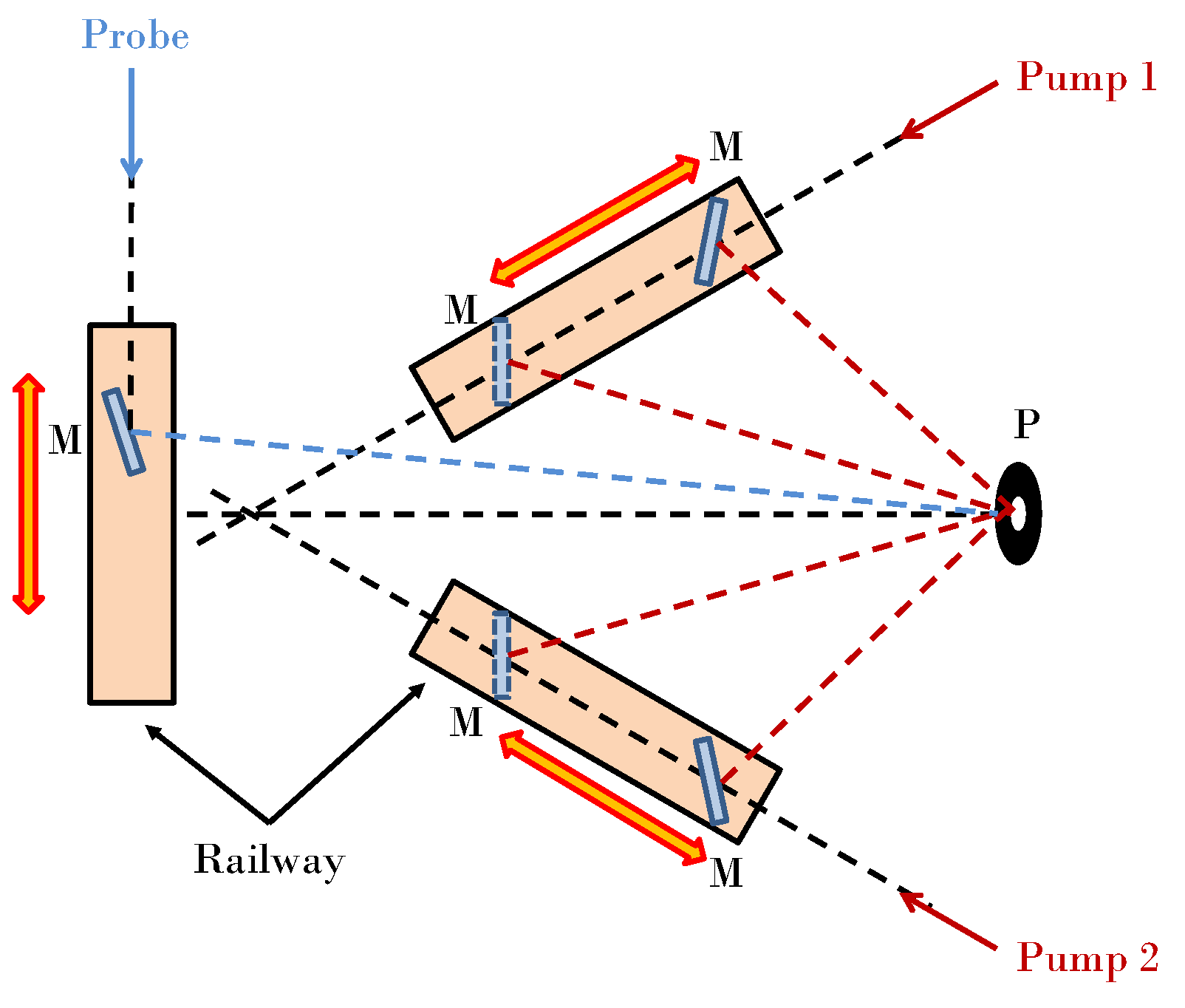
Each pump beam is sent in axis with a railway (see black dashed lines in
Figure 2). On this axis is also mounted a mirror, which can translate along the railway and can rotate on an axis orthogonal with the previous one. In this case, simply translating and rotating the mirror, different angles at the sample position can be set in a simple way. The translation and rotation positions can be read on a graduate scale, which guarantees the movements repeatability. Thanks to the proposed configuration, for each angle the beam impinges ever in the middle of the mirror. So, the continuous angles variation can be performed conserving the optical setup alignment. A pinhole, positioned on the sample position, allows the overlapping of the two pump beams (red dashed lines), without losing the spatial coincidence. The direction of the probe beam (blue dashed lines) was varied with the same kind of device to satisfy the Bragg condition, which also fixes the direction of the scattered beam. The delay of the probe beam with respect to the induced grating can be varied with a 30 cm long delay stage. The scattered pulse is then focused into an amplified silicon photodetector, connected with a Boxcar integrator and an acquisition board.
Figure 2.
Optical setup for homodyne detection with continuous angles variation. M: mirrors; P: pinhole.
Figure 2.
Optical setup for homodyne detection with continuous angles variation. M: mirrors; P: pinhole.
2.3. Homodyne Detection, Ultraviolet Pulsed Probe, EUV Pulsed Pump
The final step before TIMER is the realization of an EUV pump-Ultraviolet (UV) probe setup, based on the experimental knowledge acquired with the setup described in
Subsection 2.2. For this purpose, we have achieved a new setup based on reflective optical elements, hosted by the DiProI end-station [
26] chamber at FERMI. The experiment was based on EUV pump pulses and a UV probe pulse, with homodyne detection. A schematic sketch is reported in
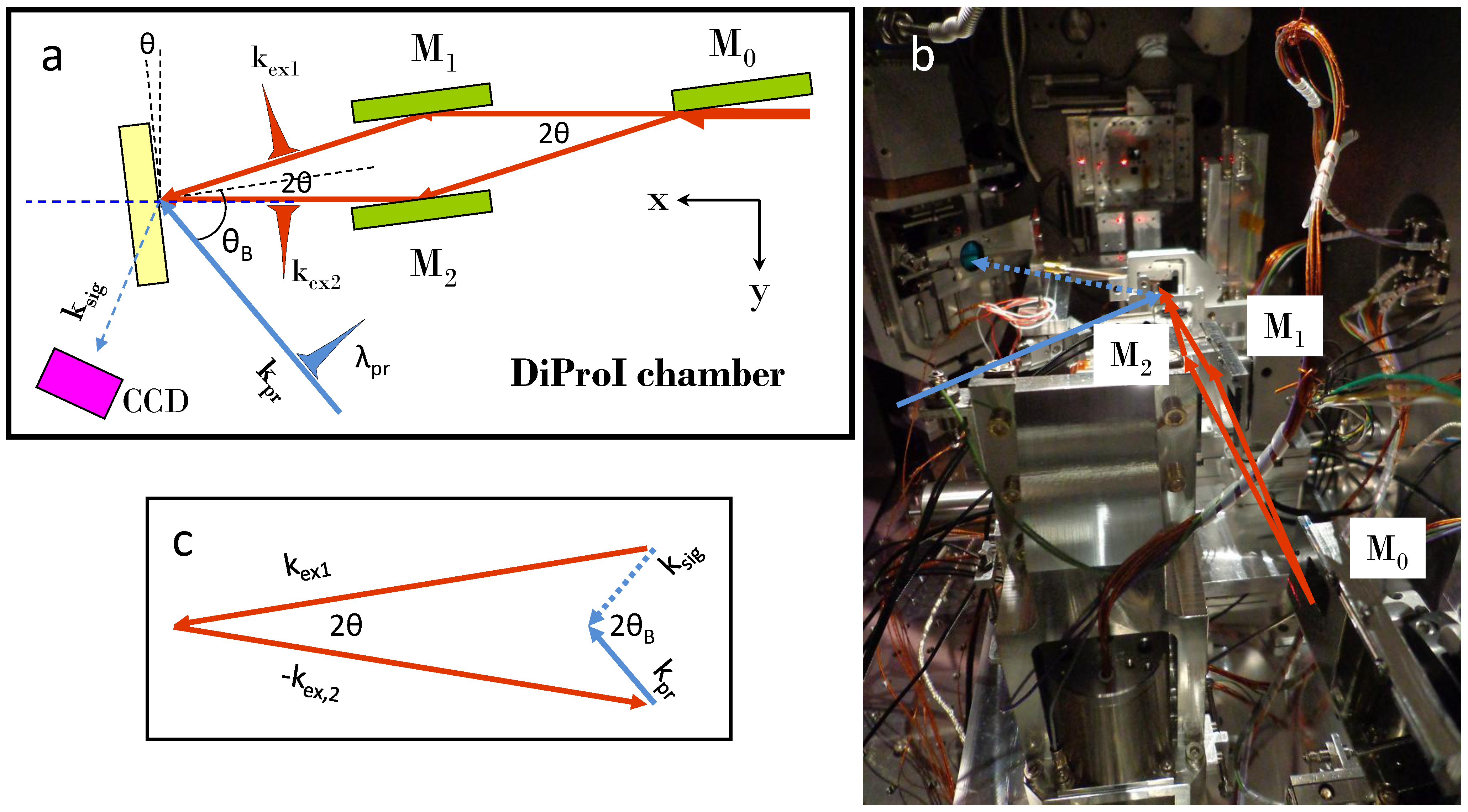
Figure 3a. The EUV radiation produced by FERMI (wavelength 27.6
nm, pulse duration 80
fs, pulse energy ≃ 5
μJ, vertical polarization) is split by the first carbon-coated mirror M0, working at grazing angle, with the idea proposed in
Subsection 2.2; the two pump beams are then recombined on the sample position by mirrors M1 and M2. The proposed geometry guarantees the temporal overlap between pump pulses at the sample position. This condition can be optimized by small adjustments of mirrors M1 and M2 (position in the x-y direction, and pitch and roll angles). Transient reflectivity measurements on Si
3N
4, as reported in [
27], allow us to set the correct temporal superposition between EUV pump and UV probe pulses (wavelength 392.8
nm, pulse duration 140
fs, pulse energy ≃ 1
μJ, vertical polarization).
In our experiment, the angle (2
θ) between pump pulses was fixed at 6°, which corresponds to
q = 23.8
μm−1 (see Equation (
1)). The use of a UV probe (obtained using a fraction of the infrared pulse that triggers the FEL emission, after passing a SHG crystal) and a EUV pump pulses fixes the spatial region which can be probed.
When pump and probe wavelengths are chosen from two so far spectral ranges, very different incident angles are required to satisfy the phase matching condition. In our case, the selected value for
θ is the lower possible, due to the spatial obstruction of mirror mounts (as can be deduced by
Figure 3b). It corresponds to a very large angle for probe beam (
θB = 49.9°, see
Figure 3c). This value is close to the maximum possible: for larger angles, the scattered beam cannot be easily detected due to the available space inside DiProI chamber.
Figure 3.
Optical setup for homodyne detection with extreme EUV pump/UV probe. Panel (a) M0, beam splitter mirror; M1,2, rotating and translating direction mirrors; red line, EUV radiation; blue line, UV radiation. Panel (b) picture of the setup installed inside DiProI chamber. Panel (c) schematic sketch of the Bragg condition between pump, probe and signal pulses wavevectors.
These experimental limitations did not allow us to reach the mesoscopic region with visible probe pulses, but the proposed setup is a really good feasibility test to understand if a TG experiment can be created with FEL pulses. The final step will be the introduction of EUV probe pulse and new geometrical configurations, as it will be for TIMER.
The FEL beam is focalized at the sample position with a Kirkpatrick-Baez active focusing system, providing a 0.04 mm2 focal spot size. The UV beam is also focalized at the same position (focal spot size 0.002 mm2).
The fluence of the FEL beam (around 12 mJ/cm2)was chosen in order to avoid any ionization effects and any creation of permanent gratings (various measures at different fluences was done in order to find the limit where damages occur, located around 50 mJ/cm2).
The scattered beam, whose direction is fixed by Equation (
2), was recorded by a Princeton Instrument PI-MTE back illuminated Charged Coupled Device (CCD). An external delay line allowed changing the temporal overlap between the probe pulse and the pump pulses (ever in reciprocal time coincidence), following in this way the relaxation dynamics of the induced grating.
3. Results and Discussion
TG signal intensity in dependence of time (in the following just called “signal”) were acquired for all the proposed configurations. Each experiment keeps attention on different dynamical regions. In fact, various setups have to be considered exploring the entire dynamical range (from hundreds of femtoseconds to microseconds). In details, the HD CW probe configuration is the best one covering longer time scale, from
ns to
μs, allowing to follow the acoustic and thermal behavior of materials. The CW probe guarantees the access to the entire dynamical range in a single measurement, making very short the acquisition time. A typical HD CW probe signal on Acetonitrile (anhydrous, 99.8% from Sigma-Aldrich) at 303
K is reported in
Figure 4.
Figure 4.
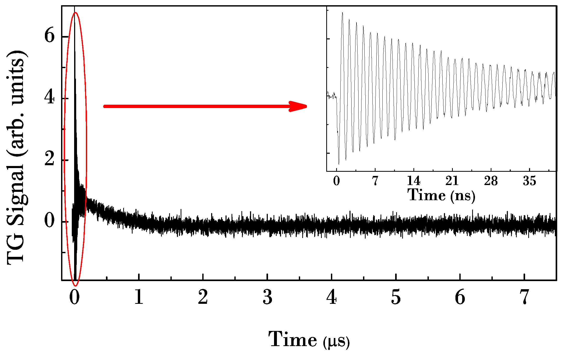
Heterodyne detected TG signal from acetonitrile at 303 K. The inset shows a zoom at short time, where damped acoustic oscillations are evident.
Figure 4.
Heterodyne detected TG signal from acetonitrile at 303 K. The inset shows a zoom at short time, where damped acoustic oscillations are evident.
The signal shows several dynamic ranges; the induced grating produced by the interference of the two pump pulses creates a spatial modulation of the dielectric constant. This launches an acoustic standing waves, which modulates the intensity of the scattered beam. The inset in
Figure 4 shows exactly these oscillations, whose amplitude is characterized by an exponential decay. The induced grating relaxes at longer time by thermal diffusion: it is reproduced by an exponential decay of the signal (see main graph). From the signal it is possible to extract the values of the sound velocity, the acoustic damping time and the thermal relaxation time. A fit of the short time portion of the signal with a damped sinusoidal function allows us to extract the sound speed. The measured value is 1263 ± 10
m/
s, in good agreement with the literature value [
28].
The main restriction of this scheme is related to the finite bandpass of electronic devices used to collect the information from the scattered beam: it limits the shorter time which can be detected, corresponding to few ns. All the information related to faster dynamics, like electron-phonon coupling and vibrational relaxations, particularly interesting for disordered systems, are unreachable.
This limitation can be easily overcome using a pulsed probe instead of a CW one, as proposed in
Subsection 2.2. The pulsed scheme is able to collect dynamical information as a function of the delay between pump and probe pulses, which can be varied in a very fine way using a mechanical delay stage. The minimum step is 1
μm, which corresponds to around 3
fs. Considering that the scattered light intensity is recorded keeping fixed the delay stage for each step, no limitations occur from the detection systems bandpass. The time window that can be covered is defined only by the time duration of the pulses (100
fs) and the total length of the delay stage (30
cm in double pass, corresponding to 2
ns).
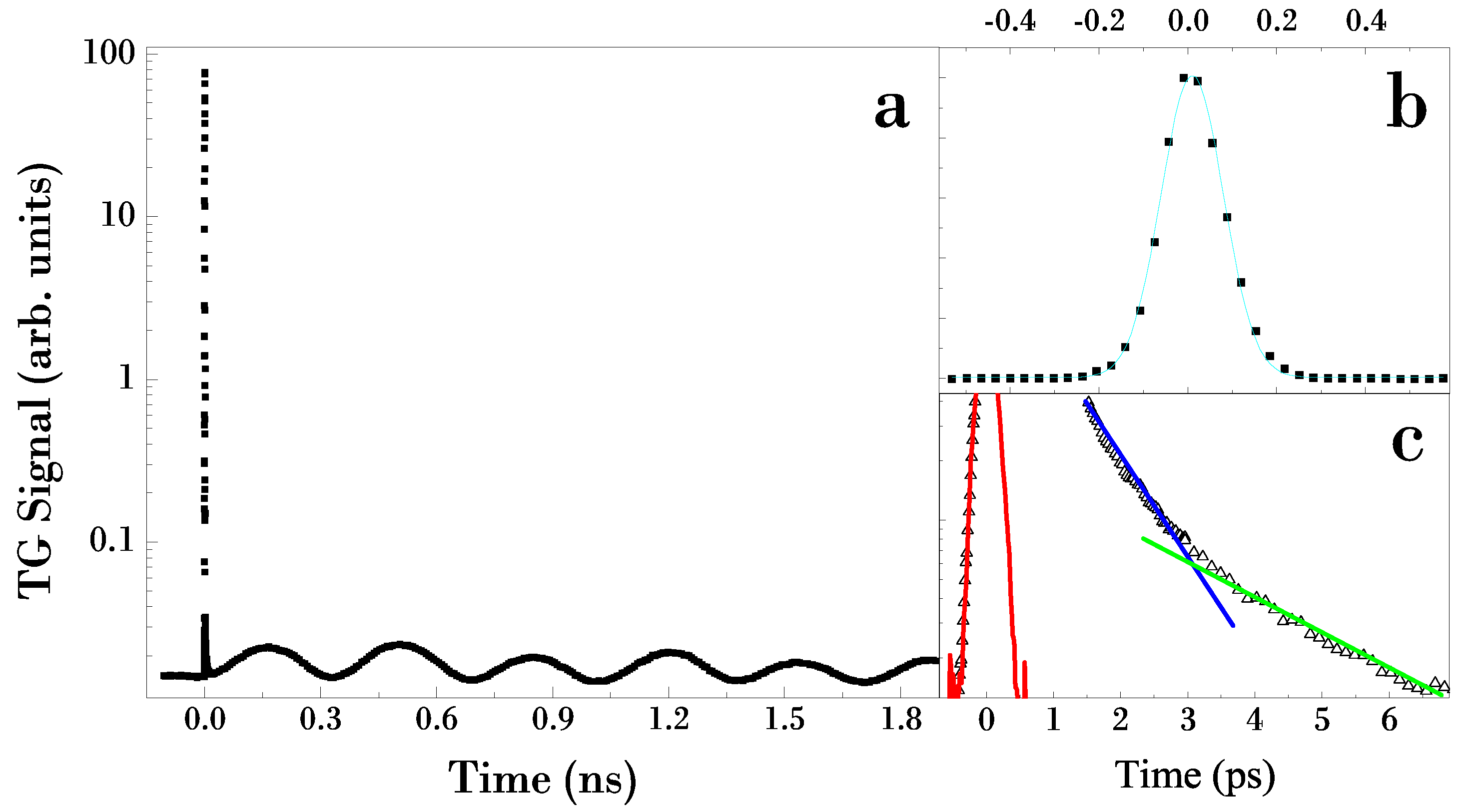
A typical signal on dimethyl sulfoxide (DMSO, purity > 99.9% from Sigma-Aldrich) at room temperature is displayed in
Figure 5a. At very short time (see
Figure 5c), the signal is characterized by a very fast rise (tens of
fs), due to the electronic response of the material. This is followed by a bi-exponential decay (few
ps), due to the vibrational and rotational relaxations of the Raman modes [
25]. The green and blue lines in
Figure 5c are eye-guides to better highlight such behavior. In the figure is also shown (red line) the signal obtained on vitreous SiO
2, which is characterized by only an electronic response at the used wavelength. Due to this aspect, this signal can be considered the X-correlation between pump and probe pulses, reproducing exactly the gaussian shape of the laser pulse. This curve is generally used as an “instrumental function” to fit the data with a theoretical model. A fit of the SiO
2 signal with a Gaussian profile (cyan line) is shown in
Figure 5b. After the Raman relaxation, the acoustic waves build up. The value of the sound velocity extracted with a fitting procedure is 1485 ± 10
m/
s, comparable with the values reported in [
29].
Figure 5.
Panel (a) homodyne detected TG signal on DMSO at room temperature. Panel (b): electronic response from SiO2 (instrumental function) with gaussian curve fit (cyan line). Panel (c): electronic and fast response on DMSO; the green and blue lines indicate the two contributions to the relaxation dynamics; the red line is the instrumental function.
The main difference between the heterodyne and the homodyne detection lies in the intensity difference between the electronic and acoustic contribution. In heterodyne detection, the electronic response is represented by the first peak in the signal, as verified for many different liquids [
19]. As evidenced in the inset of
Figure 4, the electronic and acoustic peak has the same intensity. On the other hand, in homodyne detection there is a great difference (around four orders of magnitude for the case of DMSO) between the two contributions, as can be easily deduced from
Figure 5a. In spite of this consideration, our results demonstrate the ability to extract the acoustic information with enough intense signal-to-noise ratio also in the homodyne detection, using only reflective optical elements. This information is crucial for the feasibility of the TIMER beamline, which will not have any transmission optical elements, and it is not currently designed with the heterodyne detection scheme.
Moreover, the signal is not affected by any diffraction effect, due to the mirror edge used as beam splitters. So, this solution will be also useful for table top laser systems: the use of “reflective” beam splitters, instead of the transmissive ones, avoids chirping of
fs laser pulses. The extension of this aspect to the EUV region has been considered from a theoretical point of view [
23]. This analysis, actually in progress, makes us confident on this solution also for the final TIMER setup.
The experiment described in
Subsection 2.3 was carried out on a vitreous SiO
2 sample (Suprasil glass from Corning, 1
mm thickness) at room temperature, the same used in the TG experiment with infrared pump/visible probe pulses. This type of sample is of particular interest in the framework of glassy state, due to anomalies related to the acoustic damping time [
30,
31,
32]. One goal of the TIMER project will be to answer to many questions related to this material. So, it is of great importance to test vitreous SiO
2 sample with the proposed setup. Moreover, we can compare the results obtained with EUV and infrared pump pulses on the same sample, in order to understand if the new setup based on EUV source can give us a reliable dynamical characterization. For this reason, we concentrated our attention only on the fast time scale (up to hundreds of
fs), pushing back to future experiments the full dynamical characterization of the proposed sample.
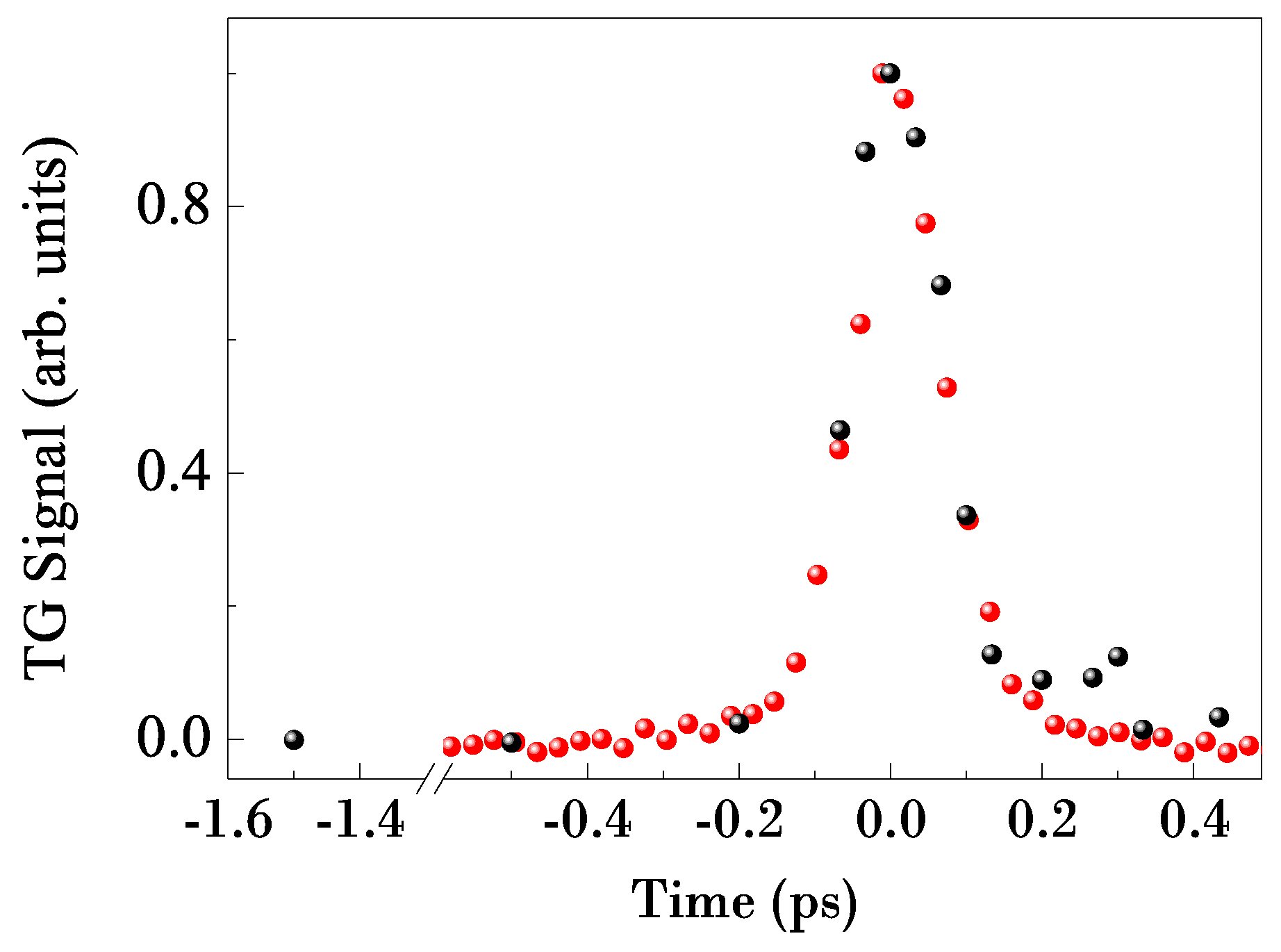
The results obtained with the EUV pump pulses setup are shown in
Figure 6 (black circles), together with the signal measured with infrared pump setup (red circles), the same reported also in
Figure 5b. Both the signals are normalized to the same intensity, in order to compare the temporal profile. Considering that, in the presence of only an electronic response, the signal is the cross correlation between pump and probe pulses, the expected temporal duration of the UV scattered signal have to be comparable with the one obtained with infrared pump pulses (the cross correlation between 80 fs EUV pulses and 140 fs UV pulse is around 160 fs, the same which can be obtained with 115 fs pulses). This is confirmed by the perfect superposition between the two signals in
Figure 6, which therefore validates unequivocally the TG feasibility with EUV pump pulses.
Figure 6.
TG signal at short time on a vitreous SiO2 sample at room temperature, obtained with EUV (black circles) and infrared (red circles) pump pulses.
Figure 6.
TG signal at short time on a vitreous SiO2 sample at room temperature, obtained with EUV (black circles) and infrared (red circles) pump pulses.
The confirmed creation of the grating inside the sample, and the good reproducibility with respect to the infrared results, open the way to the final installation of the TIMER beamline.


