Photothermal Microscopy for High Sensitivity and High Resolution Absorption Contrast Imaging of Biological Tissues


1
Faculty of Systems Engineering, Wakayama-University, Wakayama 640-8510, Japan
2
Advanced Ultrafast Laser Research Center, The University of Electro-Communications, 1-5-1 Chofugaoka, Chofu, Tokyo 182-8585, Japan
3
JST, CREST, K’ Gobancho 7, Gobancho, Chiyoda-ku, Tokyo 102-0076, Japan
4
Department of Electrophysics, National Chiao-Tung University, Hsinchu 300, Taiwan
5
Institute of Laser Engineering, Osaka University, 2-6 Yamada-oka, Suita, Osaka 565-0971, Japan
*
Author to whom correspondence should be addressed.
Photonics 2017, 4(2), 32; https://doi.org/10.3390/photonics4020032
Submission received: 13 March 2017
/
Revised: 4 April 2017
/
Accepted: 13 April 2017
/
Published: 19 April 2017
(This article belongs to the Special Issue Superresolution Optical Microscopy)
Abstract
:Photothermal microscopy is useful to visualize the distribution of non-fluorescence chromoproteins in biological specimens. Here, we developed a high sensitivity and high resolution photothermal microscopy with low-cost and compact laser diodes as light sources. A new detection scheme for improving signal to noise ratio more than 4-fold is presented. It is demonstrated that spatial resolution in photothermal microscopy is up to nearly twice as high as that in the conventional widefield microscopy. Furthermore, we demonstrated the ability for distinguishing or identifying biological molecules with simultaneous muti-wavelength imaging. Simultaneous photothermal and fluorescence imaging of mouse brain tissue was conducted to visualize both neurons expressing yellow fluorescent protein and endogenous non-fluorescent chromophores.
1. Introduction
Photothermal (PT) microscopy can visualize non-fluorescent chromophores with high sensitivity and high spatial resolution. It has been applied to visualize the distribution of endogenous chromoproteins in biological specimens such as cytochromes in mitochondria [1,2,3,4], hemoglobin in red blood cells in blood vessels [5,6], and melanin pigments in skin cancer [7]. Furthermore, gold nanoparticles have been used to identify biomolecules in antibody labelling techniques applied in cellular imaging [8,9,10,11,12]. As gold nanoparticles are physiologically inert and do not suffer from photobleaching, they are highly useful in live cell imaging.
However, in PT microscopy, an integration time of 1 to 10 ms per pixel is typically needed to attain a sufficient signal-to-noise ratio (SNR) [13]. Thus, the image acquisition time is still slower than that achieved by conventional laser scanning fluorescence microscopy, with integration times as low as 1 to 10 μs per pixel. Imaging speed is one of the most important parameters that define the performance of laser scanning microscopy. To achieve fast imaging, it is necessary to improve SNR as it decreases with measurement time. Furthermore, previous PT imaging has been single color only, and multi-wavelength imaging with multiplex biomolecule labelling is needed to distinguish and/or identify a variety of cellular components in high specificity.
In this paper, we report on the development of a high-sensitivity and high resolution PT microscope by implementing a new detection scheme in a laser scanning microscope. Simultaneous multi-wavelength imaging of biological tissues was performed with frequency division multiplexing technique. Furthermore, Multimodality imaging with PT and fluorescence images was demonstrated to visualize endogenous mouse brain signals. A method for improving spatial resolution by nearly twice as high as that of conventional widefield microscopy is also presented.
2. Experimental
2.1. Principle of PT Microscopy
PT microscopy is a form of pump and probe microscopy [14] in which two laser beams with different wavelengths for pumping and probing are incident on the sample through a focusing lens. The intensity of the pump beam is modulated typically at the frequency from 100 kHz to 1 MHz. The pump beam increases the temperature, ΔT, around the focal point of the optical absorbing sample, which results in variations in the local refractive index (typically Δn ~ 10−4 with ΔT = 1 K). Variation in the refractive index induces the deflection of the probe beam, which can be theoretically described by the Lorentz-Mie or the diffraction model [15,16]. The magnitude of the relative intensity change of the probe beam due to PT effect ΔI/I is estimated to be ~10−4 when Δn ~ 10−3–10−4. A lock-in amplifier is employed to demodulate the small signal.
2.2. Experimental Setup
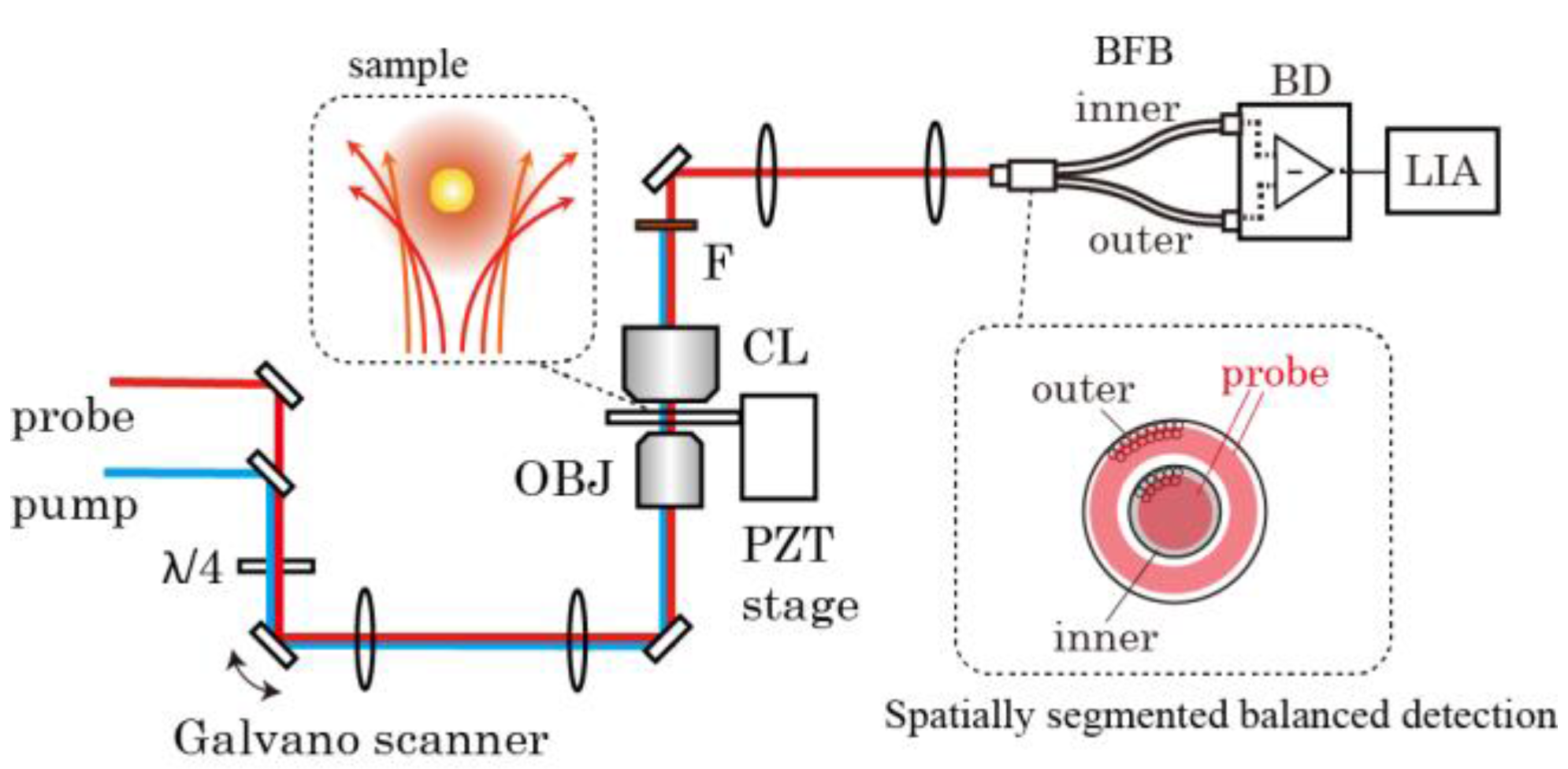
Figure 1 shows the experimental setup of our PT microscopy. Low cost and compact laser diodes (LDs) with different wavelengths were used for pumping and probing. Intensity of the pump beam was modulated through direct current modulation. Each beam was collimated through a polarization-maintaining single-mode fiber for spatial mode filtering. The combined pump and probe beams were directed to a Galvano scanner and focused on a sample through an objective lens. Focused laser beams was scanned sequentially point-by-point and the pixel information is assembled into an image. To acquire images in different focal plane (z-stack), the sample position was controlled in axial-direction using a positioning stage driven by a piezo actuator. A condenser was used to collect the entire transmitted light. A spatially segmented balanced detection method was incorporated in the system to improve SNR. The detail of this scheme is described in the following section.
PT signal increases with the pump power since it is proportional to the change in refractive index [17,18,19], but lower pump power is preferable to avoid photo and/or thermal damages on a sample. The powers of the pump beams for the excitation were typically from 0.1 mW to 3 mW depending on the absorbance of the sample. The temperature increase is estimated to be less than 10 K. On the other hand, SNR is proportional to the square root of the probe beam power in the limit of the shot noise. Thus, higher probe power is better for high sensitivity imaging as long as the sample does not absorb probe beam. The wavelength of the probe beam was selected within the range of red to near infrared to avoid optical absorption in biological tissue. In the present experiment, the wavelength of the probe beam was 640 nm and the typical value of the probe beam power was ~10 mW.
3. Results and Discussion
3.1. Improvement in SNR by the Spatially Segmented Balanced Deteciton
To achieve fast imaging as well as to avoid thermal damage on the sample, it is important to improve SNR since it decreases with the measurement time. A new detection method based on the characteristics of an angular-dependent PT signal is proposed to improve SNR.
In PT microscopy, modulating pump beam induces variations in the local refractive index, which behaves as a nano-lens and deflects the probe beam. Because of the nano-lens effect, transmitted probe beam at a large angle is modulated out of phase with respect to that at a small angle, i.e., the signal is positive (negative) at a small angle but negative (positive) at a large angle. The signal intensity vanishes when the entire transmitted probe beam is collected.
In previous reports, a low-NA condenser or an iris diaphragm placed after the condenser was used to pass only a part of the probe beam at a small angle for maximization of SNR [13,20,21]. However, as the probe beam at a large angle is modulated out of phase with respect to that at a small angle, signal intensity improves by up to two times if the inner portion and outer portion of transmitted probe beam is separated into two and then detected by a balanced (differential) detector [22].
This method also serves to reject the intensity noise of the probe beam. To implement high-sensitivity imaging in pump-probe microscopy, it is necessary to circumvent the intensity noise of the probe beam. In stimulated emission and stimulated Raman microscopy, the intensity of the pump beam is modulated at high frequency (>1 MHz) because the laser intensity noise of a solid state laser used for probing occurs primarily at low frequencies (from kilohertz to DC) in the form of 1/f noise [14,23,24]. However, in PT microscopy, the high-frequency modulation scheme reduces signal intensity because the time response of the PT signal is, in principle, determined by heat conductivity and is decreased by half at ~1 MHz for a tightly focused laser beam [25,26,27,28]. Moreover, the high-frequency modulation scheme cannot circumvent the high-frequency laser noise that usually presents in the laser diodes and amplified fiber lasers.
The balanced detection method rejects the common mode noise of the probe beam while the normal mode of the PT signal is doubled. A balanced detector is commonly used to cancel the intensity noise of the probe beam in absorption and pump-probe measurements [29,30]. In a typical setup, a part of the probe beam is separated before the sample to be detected as a reference beam. The signal and reference beams are directed to the signal and reference port of the balanced detector to cancel the common mode noise. For optimal noise rejection, signal and reference beam powers should be equal. In laser scanning microscopy, because the non-uniformity of the refractive index and stationary absorption in the sample cause the probe beam to vary in intensity during the sample scan, an auto-balanced photodetector is used to compensate for the intensity imbalance between the signal and reference beams [31,32]. However, the scan speed is limited by the response time of the autobalancing loop. Present technique is less affected by the intensity imbalance because the transmitted probe beam is separated into two after the sample. Thus, a standard balanced photodetector was used in the present setup.
To implement this method in the laser scanning microscope, a custom-made bifurcated fiber bundle was employed to separate the inner and outer part of the transmitted probe beam [33]. The incident port of the fiber bundle is placed on a plane conjugate to the pupil of the condenser lens. The inner and outer beams separated by the fiber bundle were directed to a balanced photodetector.
The PT image measured in the SBD using the bifurcated fiber bundle was compared with that measured by the conventional detection scheme. Figure 2 shows the PT images of a slice of mouse brain with and without SBD. It is confirmed that signal intensity in the SBD is about 1.8 times higher than by conventional detection. Furthermore, intensity noise of the LD is reduced by ~40%. Thus, SNR is improved by a factor of 4. This indicates that image acquisition time in SBD is about 16 times reduced from the case of conventional scheme with the same pump power, because SNR is proportion to the square root of the measurement time (time constant of lock-in amplifier). SNR further improves by optimizing the detection aperture using an annular light block placed at the pupil of the condenser lens [34]. It has been demonstrated that SNR was 9.6 times larger than that in conventional detection.
3.2. Improvement in the Spatial Resolution
In the pump-probe measurement, the signal is based on the nonlinear interaction between the two laser beams and the sample. Thus, the spatial resolution obtained using a pump-probe microscope is better than that using a conventional optical microscope (Figure 3a). The width of the lateral point spread function (PSF) in pump-probe microscopy is 0.7 times smaller than conventional optical microscope owing to the nonlinear interaction. The spatial resolution in the pump-probe microscopy is equivalent to the confocal microscopy with zero pinhole. PT microscopy is a form of a pump-probe microscopy and imaging of a single 20 nm gold nanoparticle shows that the lateral PSF in PT microscopy is close to the products of the pump and probe beam intensities at the focus (Figure 3b) [35].
Pump-probe microscopy provides optical sectioning capability, as in confocal microscopy and two-photon absorption microscopy. However, the axial PSF in PT microscopy is not the product of the pump and probe intensities. In PT microscopy with the forward detection, thermal nano-lens (thermal lens) effect produces positive and negative peaks corresponding to the focusing or defocusing of the probe beam when a sample is scanned in the axial direction [6,15,21]. This signal shape causes a serious problem in biological imaging, as the twin peaks cause distortion when reconstructing an image of a thick sample.
To eliminate this drawback, a confocal forward detection scheme has been proposed in previous studies and the experimental results have shown that a single peak with a 450-nm axial resolution is achieved when the sample is a single layer thin film [36,37]. Confocal PT microscopy was conducted with the same detection schema as the classical thermal lens setup by placing a pinhole in front of the detector to avoid an unwanted PT signal. However, it is difficult to combine the confocal PT detection with spatially-segmented balanced detection method.
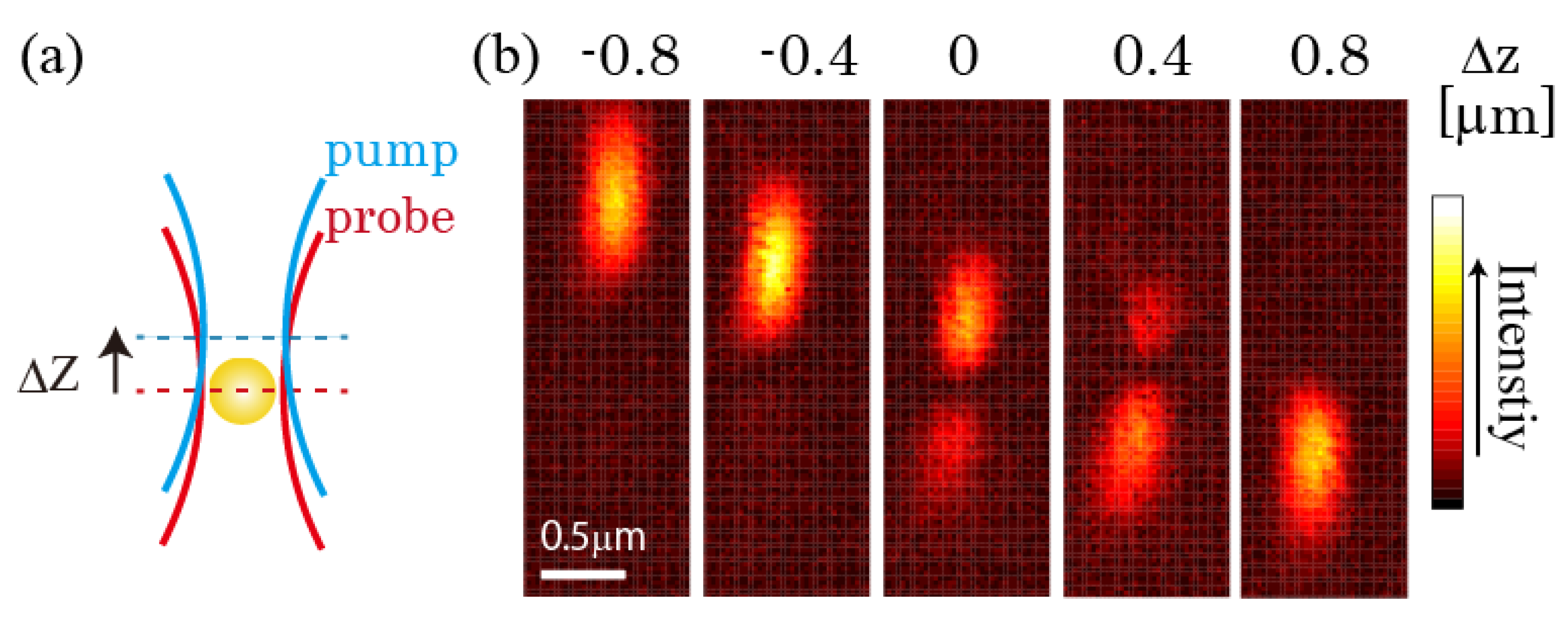
It has been also demonstrated that either of the twin peaks is suppressed by an offset between the focal planes of the pump and probe beams (Figure 4a) [35]. Figure 4b shows PT images of a 20 nm gold nanoparticle with a variety of Δz. PT signal exhibits twin peaks when the focal offset between the pump and probe beam Δz is close to zero. The amplitude images show that either of the peaks is suppressed with increasing or decreasing Δz. The focal offset can be controlled simply by the divergence of the incident beams. This method is simpler than the confocal detection setup and can easily be incorporated into the spatially-segmented balanced detection method.
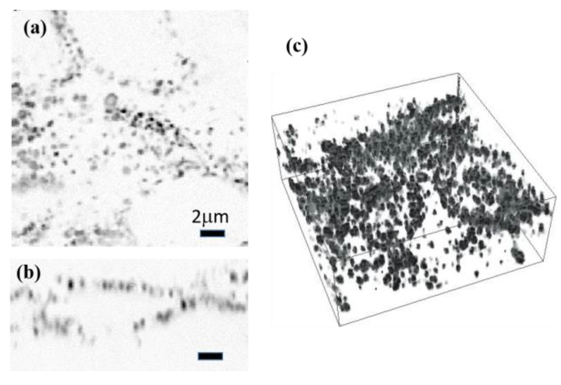
Figure 5 shows PT images of a slice of mouse melanoma in the lateral plane (Figure 5a) and axial plane (Figure 5b) with the offset scheme. The image distortion is eliminated by optimizing the offset with Δz = −0.5 μm. Figure 5c shows the reconstructed 3D image of a slice of mouse melanoma, in which the 3D distribution of melanin granules is clearly visualized.
The use of annular beams in pump-probe microscopy further improves spatial resolution. A focusing annular beam is known to exhibits a sharpened main peak with large side lobes in the focal plane (Figure 6a). The application of the annular beam has attracted much attention in the field of scanning microscopy [38,39,40,41]. Several theoretical and numerical studies have suggested that it is possible to reduce the undesired side lobes and improve lateral resolution in nonlinear imaging such as two-photon excitation (TPE) fluorescence microscopy because of square dependence of the intensity (Figure 6b) [39,40].
We examined this technique in PT microscopy by measuring a single gold nanoparticles. An annual pupil filter is placed in front of the objective lens to produce annular beams (Figure 6a). From the focal plane image of a single particle (Figure 6c), we found that fitting of with the Gaussian gives the full width at half maximum (FWHM) value of 162 nm in the transverse directions. The intensity profile exhibits only a single peak and little or no side lobes are observed. We also measured PT image of the gold nanoparticles in the case of the circular beams and found that the FWHM value is 232 nm. This result clearly demonstrates that our simple annual pupil filter is useful to improve spatial resolution in the lateral direction. Spatial resolution with annular beam is nearly twice as high as that in the conventional widefield microscopy because the FWHM of PSF with annular beam is nearly half of that of the probe intensity with the circular beam (343 nm).
The annular pupil filter severs to increase lateral resolution, but it also has some drawbacks. The annual pupil filter elongates FWHM in the axial direction. This becomes a drawback when the structures in the axial direction need to be resolved. A central and peripheral annulus filter is proposed to reduce deterioration in axial resolution [42,43]. Furthermore, the light intensity decreases to 20% after passing through the filter in our setup, which results in the reduction in SNR. One of the possible solutions to increase the beam intensity is to employ a phase plate with an apodization mask or an axicon lens to form annular beams.
3.3. Multiwavelength Imaging
Multicolor microscopic imaging is essential to visualize a variety of nanoscale cellular components with high specificity and high spatial resolution. The PT signal is proportional to the absorption cross-section of the sample material. Thus, when the sample contains different species, the measured signal is given by the linear sum of the signals from the different species. If we know the number of species in the sample and their absorption spectra, the abundance of species may be determined from spectral images (images measured with different pump wavelengths) through the spectral unmixing procedure.
PT spectral images were acquired by using a wavelength-tunable optical parametric oscillator as a pump beam with switching the laser wavelength and repeating scan [4,7]. However, this scheme would cause an error in performing spectral unmixing because of mechanical drift of the tissue or cell migration. As major advances have been made recently in high power LDs with the wavelengths from UV to NIR, simultaneous multi-wavelength imaging can be performed by incorporating multiple LDs and multi-channel lock-in amplifiers in the PT microscope with frequency-division multiplexing technique (Figure 7a) [44]. The spatial displacement of the image between the two colors was estimated to be smaller than 50 nm in the lateral direction and 0.2 μm in the axial direction, which are about one-third and one-fourth of the PSF width, respectively.
We demonstrated dual-wavelength PT imaging of a biological tissue slice stained with hematoxylin and eosin (H&E), a popular staining method widely used in histology and histopathology. Although the absorption spectra of hematoxylin and eosin overlap, their intensities depend on the wavelength: hematoxylin absorbance at 532 nm is 1.8 times larger than that at 488 nm, whereas eosin excitation efficiency at 532 nm is 2.3 times larger than that at 488 nm. This difference allows us to unmix the two channel images to determine the distribution of each species.
PT images of a part of a rabbit oocyte were acquired with excitation at 488 nm and 532 nm, respectively. Linear spectral unmixing was performed, in which pseudo-colored blue and red denote the abundance of hematoxylin and eosin, respectively (Figure 7b). In the linear spectral unmixing process, the absorption spectra of hematoxylin and eosin are used as reference spectra. The spatial displacement between the two channels is not calibrated because it is smaller than the 100-nm pixel step size. The figure clearly shows that a granule cell is stained with hematoxylin while the zona pellucida and cytoplasm are stained with eosin. We also measured sectional (XZ) images (Figure 7c) and found that tissue morphology is clearly visualized in the depth direction. Figure 7d shows a blight field image of the tissue in the same area as that in Figure 3b. Since PT microscopy gives better depth resolution than the standard widefield microscopy, higher contrast images are acquired even for a thick sample.
3.4. Multimodal Imaging of Biological Tissue
Fluorescence imaging is a well-established method for identifying specific biomolecules in a biological specimen and the combination of PT and fluorescence imaging can provides further information on the tissues since both the nonfluorescent and fluorescent molecules can be visualized [45]. A confocal fluorescence detection scheme can be incorporated in the PT microscope setup for simultaneous PT and fluorescence imaging, wherein the fluorescnece signal from the sample was detected by a photo-multiplier through a multimode fiber. PT and fluorescnece signals are simultaneously measured during the beam scan. The spatial displacements between the two images is about 0.2 μm in the lateral and axial plane, which is comparable to the spatial resolution. Furthermore, in the present imaging modality, optical transmission image can be acquired simultaneously by simply detecting the intensity of the transmitted probe beam. Multimodality imaging with PT, fluorescence, and optical transmission images will allow integration of the strengths of individual modalities and overcoming their limitations.
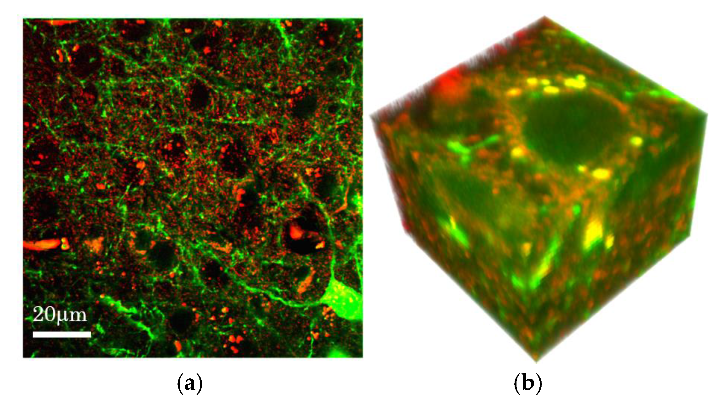
We performed simultaneous PT and fluorescnece imaging of a fixed slice of transgenic mouse brain expressing yellow fluorescent protein (YFP) [33]. Figure 8 shows the results of simultaneous PT and confocal fluorescence imaging of different layers of the mouse brain cortex. Fluorescence images visualize neurons expressing YFP at the dendrite terminals, a dendrite, and cell bodies, respectively. The PT images show distinct structures and organization. Vascular walls can be identified morphologically. They produce strong PT signals as they may contain heme proteins. The cell bodies of the neurons appear as dark shadows. Fine structures are observed in all areas of the brain cortex. Bright specks with diameters of around 1 μm appear surrounding the cell bodies. These are attributable to the lipofuscins in lysosomes as weak autofluorescence is detected [46]. Sponge-like structures of sub-micrometer size cover large areas of the tissue. The combined PT and fluorescence images show that the axon and dendrites visualized in the fluorescence image do not overlap with the fine structures in the PT images. This indicates that the contrasting agent of the sponge-like structure is outside the neuron. A 3D model is reconstructed from a stack of images in discrete z-steps (Figure 8b).
We consider that the fine sponge-like structures are presumably attributed to lipid consisting of 30–60 percent of brain. Hydrophobic dyes such as lutein and zeaxanthin that can pass blood-brain barriers and/or lipid peroxides may contribute as PT contrast agents [47,48]. It is suggested that lipid has a steeper refractive index/temperature slope (5 × 10⁻⁵–5 × 10⁻⁴ K−1), therefore chromophores in lipid results in significant PT signal. Lipid metabolism in brain is closely related to the neurodegeneration such as Alzheimer’s disease [49,50]. Therefore, the ability to imaging of both neuron and lipid structure at high spatial resolution will be a powerful technique to study such diseases.
4. Conclusions
High-sensitive and high resolution PT microscopy was developed using compact and low-cost LD as light sources. A SBD scheme is proposed to improve SNR and incorporated in the laser scanning PT microscopy using a custom-made bifurcated fiber bundle and a balanced detector. It is confirmed that SNR improves by a factor of 4 compared to the conventional detection.
Since PT microscopy is a form of pump-probe microscopy, the spatial resolution is better than the conventional optical microscope. Experimental studies show that the lateral PSF is close to the product of the pump and probe intensities at the focal. On the contrary, axial PSF exhibits twin peaks corresponding to the focusing or defocusing of the probe beam due to the thermal nano-lens effect. To reduce the distortion due to the twin peak, either of the twin peaks is suppressed by an offset between the focal planes of the pump and probe beams. By this offset scheme, high fidelity and high resolution 3D imaging of a slice of mouse melanoma is demonstrated. This method can be combined with the SBD scheme in contrast to the confocal PT microscope. The use of annular beams in pump-probe microscopy further improves lateral resolution by a factor of 1.43.
Multimodality imaging with PT and fluorescence provides further information on the tissues since both the nonfluorescent and fluorescent molecules can be visualized. Simultaneous PT and confocal fluorescence imaging of transgenic mouse brain expressing YFP is demonstrated. Fluorescence images visualize neurons expressing YFP, while PT method detect endogenous non-fluorescent chromophores in brain and various organizations such as blood cell, vascular wall, lipofuscin in lysosomes, and fine sponge structures which are presumably attributable to lipid are visualized. Since present imaging modality is based on compact and low-cost laser diodes, it will be widely useful for life and medical sciences.
Acknowledgments
The authors would like to thank Prof. Haruo Kasai from the Graduate School of Medicine, The University of Tokyo and Dr. Hiromichi Tsurui from the Department of Pathology, Juntendo University School of Medicine for providing the biological samples.
Author Contributions
All the authors contributed to the development of the work and the writing of the manuscript.
Conflicts of Interest
The authors declare no conflict of interest. The founding sponsors had no role in the design of the study; in the collection, analyses, or interpretation of data; in the writing of the manuscript, and in the decision to publish the results.
References
- Tamaki, E.; Sato, K.; Tokeshi, M.; Sato, K.; Aihara, M.; Kitamori, T. Single-cell analysis by a scanning thermal lens microscope with a microchip: Direct monitoring of cytochrome c distribution during apoptosis process. Anal. Chem. 2002, 74, 1560–1564. [Google Scholar] [CrossRef] [PubMed]
- Lasne, D.; Blab, G.A.; De Giorgi, F.; Ichas, F.; Lounis, B.; Cognet, L. Label-free optical imaging of mitochondria in live cells. Opt. Express 2007, 15, 14184–14193. [Google Scholar] [CrossRef] [PubMed]
- Brusnichkin, A.V.; Nedosekin, D.A.; Galanzha, E.I.; Vladimirov, Y.A.; Shevtsova, E.F.; Proskurnin, M.A.; Zharov, V.P. Ultrasensitive label-free photothermal imaging, spectral identification, and quantification of cytochrome c in mitochondria, live cells, and solutions. J. Biophotonics 2010, 3, 791–806. [Google Scholar] [CrossRef] [PubMed]
- Nedosekin, D.A.; Galanzha, E.I.; Ayyadevara, S.; Shmookler Reis, R.J.; Zharov, V.P. Photothermal confocal spectromicroscopy of multiple cellular chromophores and fluorophores. Biophys. J. 2012, 102, 672–681. [Google Scholar] [CrossRef] [PubMed]
- Lu, S.; Min, W.; Chong, S.; Holtom, G.R.; Xie, X.S. Label-free imaging of heme proteins with two-photon excited photothermal lens microscopy. Appl. Phys. Lett. 2010, 96, 113701. [Google Scholar] [CrossRef]
- Tong, L.; Liu, Y.; Dolash, B.D.; Jung, Y.; Slipchenko, M.N.; Bergstrom, D.E.; Cheng, J.X. Label-free imaging of semiconducting and metallic carbon nanotubes in cells and mice using transient absorption microscopy. Nat. Nanotechnol. 2012, 7, 56–61. [Google Scholar] [CrossRef] [PubMed]
- Nedosekin, D.A.; Shashkov, E.V.; Galanzha, E.I.; Hennings, L.; Zharov, V.P. Photothermal multispectral image cytometry for quantitative histology of nanoparticles and micrometastasis in intact, stained and selectively burned tissues. Cytom. Part A 2010, 77, 1049–1058. [Google Scholar] [CrossRef] [PubMed]
- Cognet, L.; Tardin, C.; Boyer, D.; Choquet, D.; Tamarat, P.; Lounis, B. Single metallic nanoparticle imaging for protein detection in cells. Proc. Natl. Acad. Sci. USA 2003, 100, 11350–11355. [Google Scholar] [CrossRef] [PubMed]
- Leduc, C.; Jung, J.M.; Carney, R.P.; Stellacci, F.; Lounis, B. Direct investigation of intracellular presence of gold nanoparticles via photothermal heterodyne imaging. ACS Nano 2011, 5, 2587–2592. [Google Scholar] [CrossRef] [PubMed]
- Leduc, C.; Si, S.; Gautier, J.; Soto-Ribeiro, M.; Wehrle-Haller, B.; Gautreau, A.; Giannone, G.; Cognet, L.; Lounis, B. A highly specific gold nanoprobe for live-cell single-molecule imaging. Nano Lett. 2013, 13, 1489–1494. [Google Scholar] [CrossRef] [PubMed]
- Lasne, D.; Blab, G.A.; Berciaud, S.; Heine, M.; Groc, L.; Choquet, D.; Cognet, L.; Lounis, B. Single nanoparticle photothermal tracking (SNaPT) of 5-nm gold beads in live cells. Biophys. J. 2006, 91, 4598–4604. [Google Scholar] [CrossRef] [PubMed]
- Octeau, V.; Cognet, L.; Duchesne, L.; Lasne, D.; Schaeffer, N.; Fernig, D.G.; Lounis, B. Photothermal absorption correlation spectroscopy. ACS Nano 2009, 3, 345–350. [Google Scholar] [CrossRef] [PubMed]
- Vermeulen, P.; Cognet, L.; Lounis, B. Photothermal microscopy: Optical detection of small absorbers in scattering environments. J. Microsc. 2014, 254, 115–121. [Google Scholar] [CrossRef] [PubMed]
- Wei, L.; Min, W. Pump-probe optical microscopy for imaging nonfluorescent chromophores. Anal. Bioanal. Chem. 2012, 403, 2197–2202. [Google Scholar] [CrossRef] [PubMed]
- Selmke, M.; Braun, M.; Cichos, F. Nano-lens diffraction around a single heated nano particle. Opt. Express 2012, 20, 8055. [Google Scholar] [CrossRef] [PubMed]
- Selmke, M.; Braun, M.; Cichos, F. Photothermal single-particle microscopy: Detection of a nanolens. ACS Nano 2012, 6, 2741–2749. [Google Scholar] [CrossRef] [PubMed]
- Paulo, P.M.R.; Gaiduk, A.; Kulzer, F.; Krens, S.F.G.; Spaink, H.P.; Schmidt, T.; Orrit, M. Photothermal correlation spectroscopy of gold nanoparticles in solution. J. Phys. Chem. C 2009, 113, 11451–11457. [Google Scholar] [CrossRef]
- Chang, W.-S.; Link, S. Enhancing the sensitivity of single-particle photothermal imaging with thermotropic liquid crystals. J. Phys. Chem. Lett. 2012, 3, 1393–1399. [Google Scholar] [CrossRef] [PubMed]
- Parra-Vasquez, A.N.G.; Oudjedi, L.; Cognet, L.; Lounis, B. Nanoscale thermotropic phase transitions enhancing photothermal microscopy signals. J. Phys. Chem. Lett. 2012, 3, 1400–1403. [Google Scholar] [CrossRef] [PubMed]
- Proskurnin, M.A.; Volkov, D.S.; Gor'kova, T.A.; Bendrysheva, S.N.; Smirnova, A.P.; Nedosekin, D.A. Advances in thermal lens spectrometry. J. Anal. Chem. 2015, 70, 249–276. [Google Scholar] [CrossRef]
- Uchiyama, K.; Hibara, A.; Kimura, H.; Sawada, T.; Kitamori, T. Thermal lens microscope. Jpn. J. Appl. Phys. 2000, 39, 5316–5322. [Google Scholar] [CrossRef]
- Miyazaki, J.; Tsurui, H.; Kawasumi, K.; Kobayashi, T. Sensitivity enhancement of photothermal microscopy with radially segmented balanced detection. Opt. Lett. 2015, 40, 479–482. [Google Scholar] [CrossRef] [PubMed]
- Min, W.; Lu, S.; Chong, S.; Roy, R.; Holtom, G.R.; Xie, X.S. Imaging chromophores with undetectable fluorescence by stimulated emission microscopy. Nature 2009, 461, 1105–1109. [Google Scholar] [CrossRef] [PubMed]
- Ozeki, Y.; Kitagawa, Y.; Sumimura, K.; Nishizawa, N.; Umemura, W.; Kajiyama, S.; Fukui, K.; Itoh, K. Stimulated Raman scattering microscope with shot noise limited sensitivity using subharmonically synchronized laser pulses. Opt. Express 2010, 18, 13708–13719. [Google Scholar] [CrossRef] [PubMed]
- Berciaud, S.; Cognet, L.; Blab, G.A.; Lounis, B. Photothermal heterodyne imaging of individual nonfluorescent nanoclusters and nanocrystals. Phys. Rev. Lett. 2004, 93, 257402. [Google Scholar] [CrossRef] [PubMed]
- Boyer, D.; Tamarat, P.; Maali, A.; Lounis, B.; Orrit, M. Photothermal imaging of nanometer-sized metal particles among scatterers. Science 2002, 297, 1160–1163. [Google Scholar] [CrossRef] [PubMed]
- Berciaud, S.; Lasne, D.; Blab, G.A.; Cognet, L.; Lounis, B. Photothermal heterodyne imaging of individual metallic nanoparticles: Theory versus experiment. Phys. Rev. B 2006, 73, 045424. [Google Scholar] [CrossRef]
- Selmke, M.; Heber, A.; Braun, M.; Cichos, F. Photothermal single particle microscopy using a single laser beam. Appl. Phys. Lett. 2014, 105, 013511. [Google Scholar] [CrossRef]
- Seto, K.; Okuda, Y.; Tokunaga, E.; Kobayashi, T. Multiplex stimulated Raman imaging with white probe-light from a photonic-crystal fibre and with multi-wavelength balanced detection. J. Phys. D Appl. Phys. 2014, 47, 345401. [Google Scholar] [CrossRef]
- Celebrano, M.; Kukura, P.; Renn, A.; Sandoghdar, V. Single-molecule imaging by optical absorption. Nat. Photonics 2011, 5, 95–98. [Google Scholar] [CrossRef]
- Hu, C.R.; Slipchenko, M.N.; Wang, P.; Wang, P.; Lin, J.D.; Simpson, G.; Hu, B.; Cheng, J.X. Stimulated Raman scattering imaging by continuous-wave laser excitation. Opt. Lett. 2013, 38, 1479–1481. [Google Scholar] [CrossRef] [PubMed]
- Freudiger, C.W.; Yang, W.; Holtom, G.R.; Peyghambarian, N.; Xie, X.S.; Kieu, K.Q. Stimulated Raman scattering microscopy with a robust fibre laser source. Nat. Photonics 2014, 8, 153–159. [Google Scholar] [CrossRef] [PubMed]
- Miyazaki, J.; Iida, T.; Tanaka, S.; Hayashi-Takagi, A.; Kasai, H.; Okabe, S.; Kobayashi, T. Fast 3D visualization of endogenous brain signals with high-sensitivity laser scanning photothermal microscopy. Biomed. Opt. Express 2016, 7, 1702–1710. [Google Scholar] [CrossRef] [PubMed]
- Miyazaki, J. Improvement of signal-to-noise ratio in photothermal microscopy by optimizing detection aperture. Opt. Commun. 2017, 390, 99–104. [Google Scholar] [CrossRef]
- Miyazaki, J.; Tsurui, H.; Kobayashi, T. Reduction of distortion in photothermal microscopy and its application to the high-resolution three-dimensional imaging of nonfluorescent tissues. Biomed. Opt. Express 2015, 6, 3217–3224. [Google Scholar] [CrossRef] [PubMed]
- Moreau, J.; Loriette, V. Confocal dual-beam thermal-lens microscope: Model and experimental results. Jpn. J. Appl. Phys. 2006, 45, 7141–7151. [Google Scholar] [CrossRef]
- Moreau, J.; Loriette, V. Confocal thermal-lens microscope. Opt. Lett. 2004, 29, 1488–1490. [Google Scholar] [CrossRef] [PubMed]
- Serrels, K.A.; Ramsay, E.; Reid, D.T. 70 nm resolution in subsurface optical imaging of silicon integrated-circuits using pupil-function engineering. Appl. Phys. Lett. 2009, 94, 073113. [Google Scholar] [CrossRef]
- Hell, S.W.; Hanninen, P.E.; Kuusisto, A.; Schrader, M.; Soini, E. Annular aperture two-photon excitation microscopy. Opt. Commun. 1995, 117, 20–24. [Google Scholar] [CrossRef]
- Mondal, P.P.; Diaspro, A. Lateral resolution improvement in two-photon excitation microscopy by aperture engineering. Opt. Commun. 2008, 281, 1855–1859. [Google Scholar] [CrossRef]
- Sick, B.; Hecht, B.; Novotny, L. Orientational imaging of single molecules by annular illumination. Phys. Rev. Lett. 2000, 85, 4482–4485. [Google Scholar] [CrossRef] [PubMed]
- Botcherby, E.J.; Juškaitis, R.; Wilson, T. Scanning two photon fluorescence microscopy with extended depth of field. Opt. Commun. 2006, 268, 253–260. [Google Scholar] [CrossRef]
- Purnapatra, S.B.; Bera, S.; Mondal, P.P. Spatial filter based bessel-like beam for improved penetration depth imaging in fluorescence microscopy. Sci. Rep. 2012, 2, 692. [Google Scholar] [CrossRef] [PubMed]
- Miyazaki, J.; Tsurui, H.; Kawasumi, K.; Kobayashi, T. Simultaneous dual-wavelength imaging of nonfluorescent tissues with 3D subdiffraction photothermal microscopy. Opt. Express 2015, 23, 3647–3656. [Google Scholar] [CrossRef] [PubMed]
- Gaiduk, A.; Ruijgrok, P.V.; Yorulmaz, M.; Orrit, M. Making gold nanoparticles fluorescent for simultaneous absorption and fluorescence detection on the single particle level. Phys. Chem. Chem. Phys. 2011, 13, 149–153. [Google Scholar] [CrossRef] [PubMed]
- Kwan, A.C.; Duff, K.; Gouras, G.K.; Webb, W.W. Optical visualization of Alzheimer’s pathology via multiphoton-excited intrinsic fluorescence and second harmonic generation. Opt. Express 2009, 17, 3679–3689. [Google Scholar] [CrossRef] [PubMed]
- Johnson, E.J. A possible role for lutein and zeaxanthin in cognitive function in the elderly. Am. J. Clin. Nutr. 2012, 96, 1161S–1165S. [Google Scholar] [CrossRef] [PubMed]
- Hammond, B.R., Jr.; Renzi, L.M. Carotenoids. Adv. Nutr. 2013, 4, 474–476. [Google Scholar] [CrossRef] [PubMed]
- Liu, J.P.; Tang, Y.; Zhou, S.; Toh, B.H.; McLean, C.; Li, H. Cholesterol involvement in the pathogenesis of neurodegenerative diseases. Mol. Cell. Neurosci. 2010, 43, 33–42. [Google Scholar] [CrossRef] [PubMed]
- Benseny-Cases, N.; Klementieva, O.; Cotte, M.; Ferrer, I.; Cladera, J. Microspectroscopy (mu FTIR) reveals co-localization of lipid oxidation and amyloid plaques in human alzheimer disease brains. Anal. Chem. 2014, 86, 12047–12054. [Google Scholar] [CrossRef] [PubMed]
Figure 1.
Photothermal microscope setup with spatially segmented balanced detection using a bifurcated fiber bundle (BFB). OBL: objective lens, CL: condenser lens, F: filter, BD: balanced detector, LIA: lock-in amplifier.
Figure 1.
Photothermal microscope setup with spatially segmented balanced detection using a bifurcated fiber bundle (BFB). OBL: objective lens, CL: condenser lens, F: filter, BD: balanced detector, LIA: lock-in amplifier.

Figure 2.
Improvement in the signal to noise ratio with the spatially segmented balanced detection: Phothothermal images of a slice of mouse bran (a) without and (b) with spatially segmented balanced detection (SBD). Pump beam power incident on the sample were 1 mW. The wavelengths of the pump and probe beam were 520 nm, and 640 nm, respectively. Image acquisition time was 6 s at 500 × 500 pixels. (c) Intensity profiles along the horizontal lines in (a) (black) and (b) (blue).
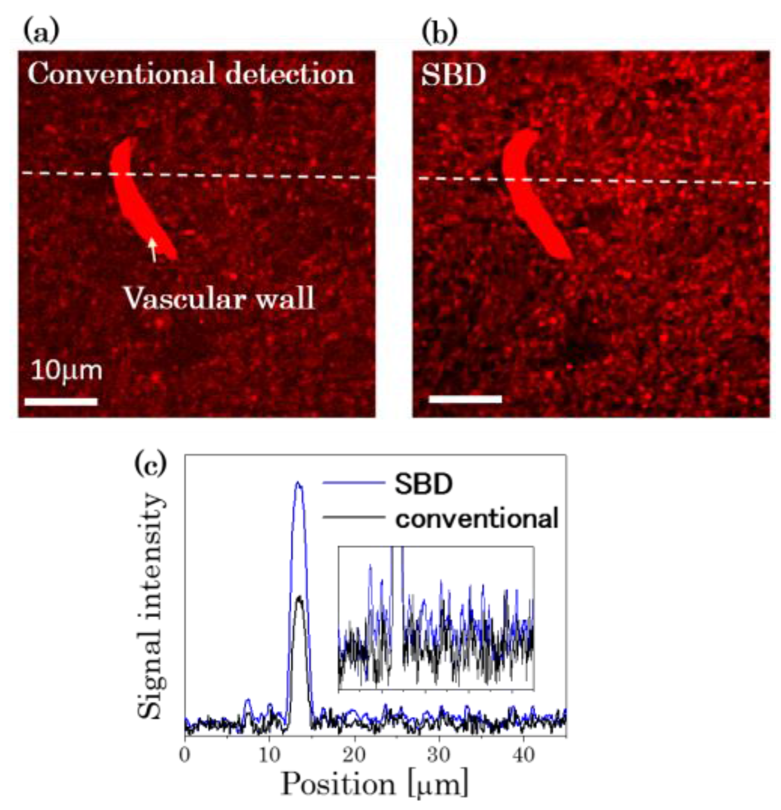
Figure 3.
Spatial resolution in the lateral plane: (a) Conceptual diagram of point spread function (PSF) in pump probe microscopy. PSF is given by the product of pump and probe intensities at the focal. (b) Intensity profiles of pump (blue) and probe (red) beams in the lateral plane as measured using a knife edge method. The lateral PSF is obtained by imaging a 20 nm gold nanoparticle (inset). The wavelengths of the pump and probe beam were 488 nm and 640 nm, respectively. The numerical aperture of the objective lens is 0.95. For the sample preparation, gold nanoparticles are dispersed in a polyvinyl alcohol (PVA) film on a glass slide. The wavelength of the pump beam overlapped the absorption spectrum of the gold nanoparticles due to the plasmon resonance peak at 524 nm.
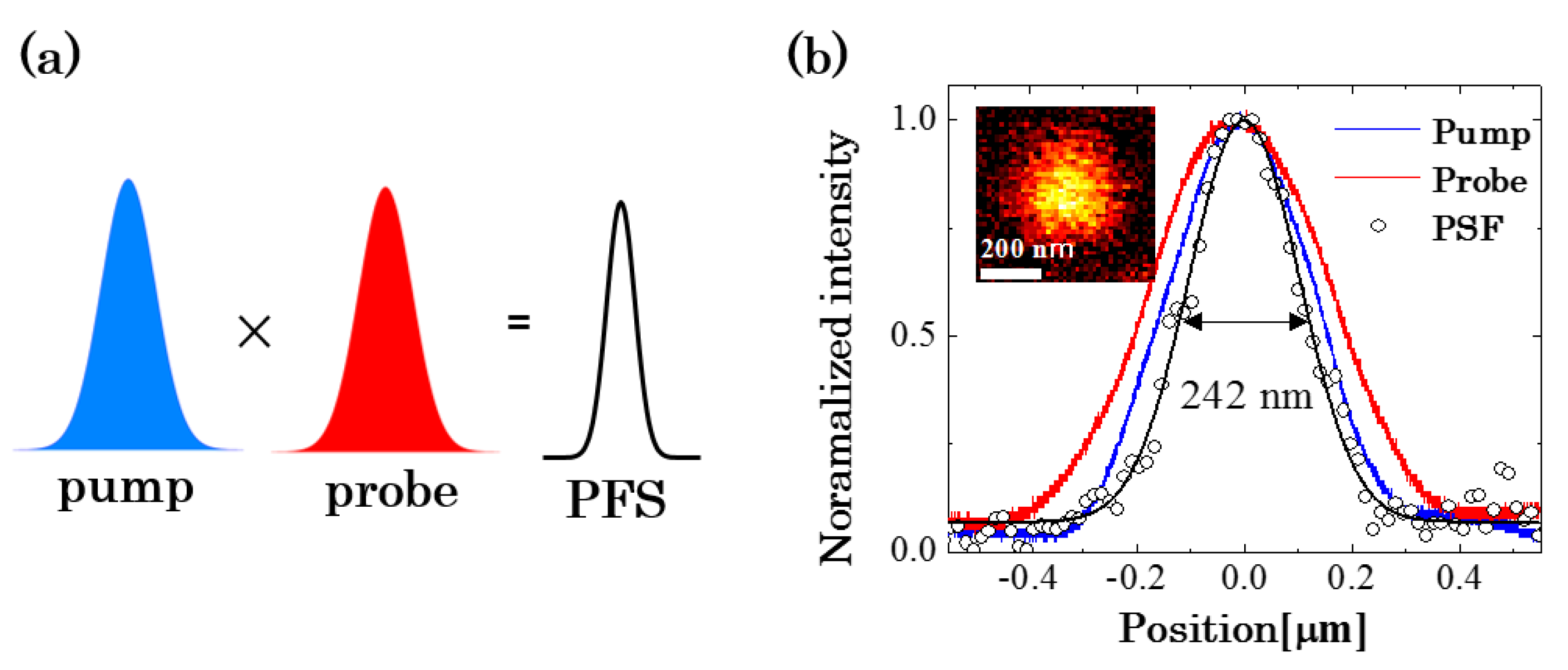
Figure 4.
Spatial resolution in the axial plane: (a) Focal offset between the pump and probe beam at the focal. (b) Photothermal (PT) images of a single gold nanoparticle in the axial plane with several values of Δz.
Figure 4.
Spatial resolution in the axial plane: (a) Focal offset between the pump and probe beam at the focal. (b) Photothermal (PT) images of a single gold nanoparticle in the axial plane with several values of Δz.

Figure 5.
Photothermal images of a slice of mouse melanoma in the (a) lateral and (b) axial planes. (c) 3D rendering of a set of 30 image slices. Image size is 19.6 × 19.6 × 8.2 μm3.
Figure 5.
Photothermal images of a slice of mouse melanoma in the (a) lateral and (b) axial planes. (c) 3D rendering of a set of 30 image slices. Image size is 19.6 × 19.6 × 8.2 μm3.

Figure 6.
Improvement in the spatial resolution with the annular beams: (a) Intensity profiles of the annular and circular beams at the focal. An annular pupil filter was used to produce the annular beams; (b) Point spread function in pump-probe microscopy with the annular beams; (c) Photothermal images of 20 nm gold nanoparticles with the (left) circular and (right) annular beams. (c) Single particle images with the circular (left) and annular (right) beams, respectively. Their intensity profiles in the transverse direction (bottom). A 488-nm LD and a 640-nm LD were used for the pump and probe beams. The numerical aperture of the objective lens is 0.95.
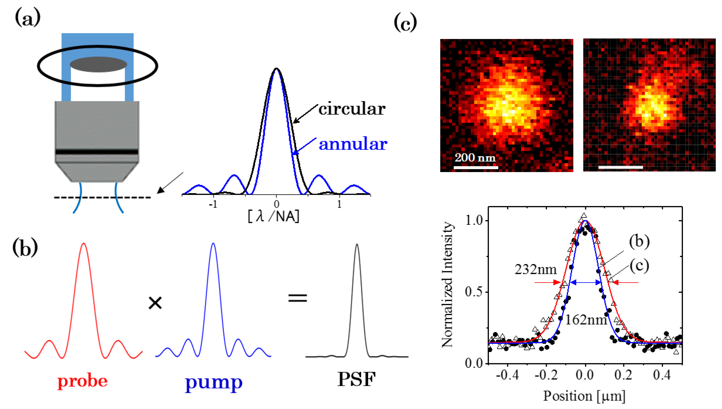
Figure 7.
Simultaneous dual-wavelength photothermal imaging with the frequency multiplexing technique: (a) Schematic illustration of dual-wavelength photothermal imaging setup. Two pump beams were modulated at different frequencies. The signals were demodulated with multichannel lock-in amplifiers; (b) Dual-wavelength PT images of H&E stained biological tissue in the lateral (b) and (c) axial planes, respectively. (d) Bright field image of the tissue in the same area as that in (b).
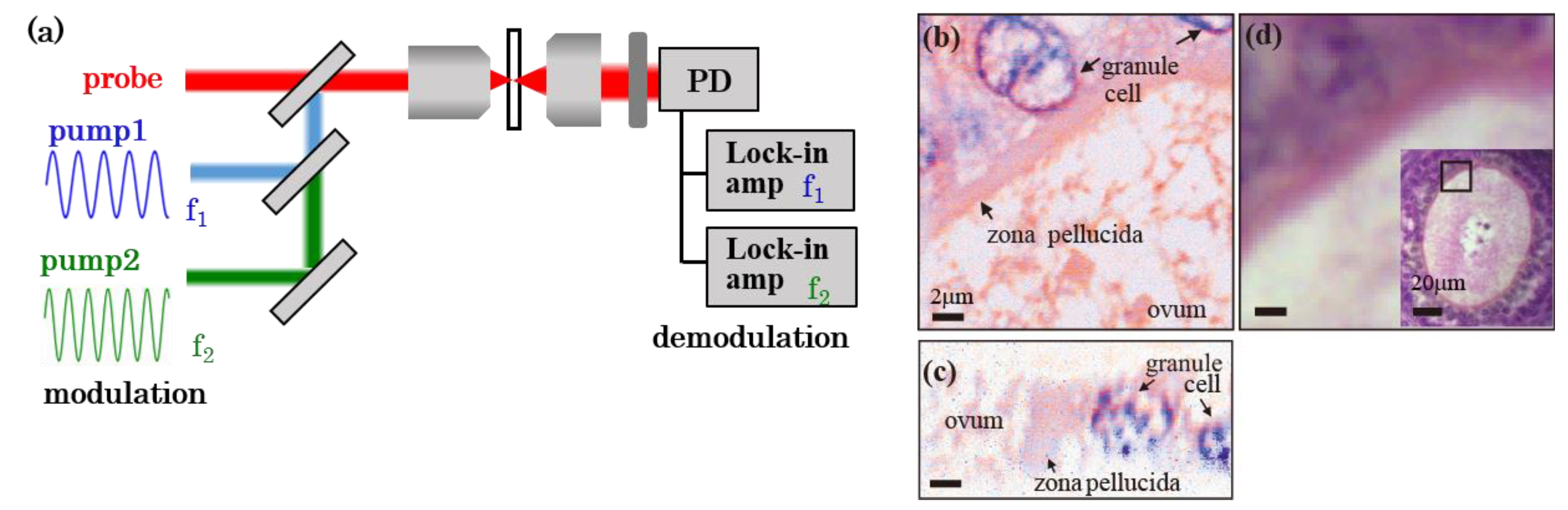
Figure 8.
Simultaneous photothermal (red) and fluorescence (green) imaging of a slice of mouse brain. The wavelengths of pump and probe beams were 405 nm and 640 nm, respectively. (b) Reconstructed 3D model of PT signal in cortex. Image size is 19.1 × 19.1 × 15.7 μm3.
Figure 8.
Simultaneous photothermal (red) and fluorescence (green) imaging of a slice of mouse brain. The wavelengths of pump and probe beams were 405 nm and 640 nm, respectively. (b) Reconstructed 3D model of PT signal in cortex. Image size is 19.1 × 19.1 × 15.7 μm3.

© 2017 by the authors. Licensee MDPI, Basel, Switzerland. This article is an open access article distributed under the terms and conditions of the Creative Commons Attribution (CC BY) license (http://creativecommons.org/licenses/by/4.0/).
Share and Cite
MDPI and ACS Style
Miyazaki, J.; Kobayahsi, T. Photothermal Microscopy for High Sensitivity and High Resolution Absorption Contrast Imaging of Biological Tissues. Photonics 2017, 4, 32. https://doi.org/10.3390/photonics4020032
AMA Style
Miyazaki J, Kobayahsi T. Photothermal Microscopy for High Sensitivity and High Resolution Absorption Contrast Imaging of Biological Tissues. Photonics. 2017; 4(2):32. https://doi.org/10.3390/photonics4020032
Chicago/Turabian StyleMiyazaki, Jun, and Takayoshi Kobayahsi. 2017. "Photothermal Microscopy for High Sensitivity and High Resolution Absorption Contrast Imaging of Biological Tissues" Photonics 4, no. 2: 32. https://doi.org/10.3390/photonics4020032
Note that from the first issue of 2016, this journal uses article numbers instead of page numbers. See further details here.