Article

Comparative Issues of Cathode Materials for Li-Ion Batteries

1
Physicochimie des Electrolytes et Nanosystèmes Interfaciaux (PHENIX), Université Pierre et Marie Curie—Paris6, UMR 8234, 4 place Jussieu, Paris 75005, France
2
Institut de Minéralogie, de Physique des Matériaux et de Cosmochimie (IMPMC), UPMC Université Paris 06, 4 place Jussieu, Paris 75005, France
3
Energy Storage and Conversion, Research Institute of Hydro-Québec, Varennes, QC J3X 1S1, Canada
*
Author to whom correspondence should be addressed.
Inorganics 2014, 2(1), 132-154; https://doi.org/10.3390/inorganics2010132
Submission received: 29 January 2014 / Revised: 10 March 2014 / Accepted: 12 March 2014 / Published: 25 March 2014
(This article belongs to the Special Issue Energy Storage and Conversion)

Abstract

:
After an introduction to lithium insertion compounds and the principles of Li-ion cells, we present a comparative study of the physical and electrochemical properties of positive electrodes used in lithium-ion batteries (LIBs). Electrode materials include three different classes of lattices according to the dimensionality of the Li+ ion motion in them: olivine, layered transition-metal oxides and spinel frameworks. Their advantages and disadvantages are compared with emphasis on synthesis difficulties, electrochemical stability, faradaic performance and security issues.

1. Introduction

Since three decades, lithium-ion batteries (LIBs) have been amongst the most promising chemical-electrical energy converter (rechargeable or secondary sources) for power electronic devices such as cellular phones, laptop computers, camera, etc. In 1992, the commercial success of LIBs based on carbon, a non-aqueous electrolyte, and lithium cobaltate (LiCoO2) offered great promise as being the first rechargeable battery technology for personal electronics in the near future [1]. Today, this technology is applied to green transportation systems such as electric vehicles (EVs) or hybrid EVs (HEVs). The increase in the demand of highly functionalized applications always includes higher power density, higher energy density, excellent charge-discharge cycling performance, and more safety.
A key element that limits the performance of the batteries is the active element of the positive electrode, and it is also the most expensive part. From 1980 to present, continuous efforts have been devoted by Goodenough to propose and study oxides compounds based on transition-metal (TM) element with focus to those compounds that crystallize in structures that favour large mobility of the Li+ ions in order to transfer energy during the redox reaction. Milestones were made in 1980 for the LiCoO2 layered structure [2], 1986 for LiMn2O4 spinels [3,4] and 1997 for the LiMPO4 (M = Fe, Mn, etc.) olivine family [5]. Rapidly, all these substances have been widely studied and effectively applied to the construction of commercial Li-ion batteries. Layered materials are used as cathodes for high-energy systems [6,7], while spinel oxides and olivines are considered in the case of high-power Li-ion batteries because low cost and long-life requirements, respectively [8,9]. However, these lithium-insertion compounds must fulfil specific properties such as chemical stability, capacity, rate capability, toxicity, cost and safety. All of them, however, achieve theoretical specific capacity >140 mAh g1 at a potential >3.4 V vs. Li0/Li+. Table 1 summarizes the electrochemical properties of the three classes of insertion compounds.
Table 1. Electrochemical characteristics of the three classes of insertion compounds.
FrameworkCompoundSpecific capacity a (mAh g−1)Average potential (Vvs. Li0/Li+)
LayeredLiCoO2 272 (140)4.2
LiNi1/3Mn1/3Co1/3O2272 (200)4.0
SpinelLiMn2O4 148 (120)4.1
LiMn3/2Ni1/2O4148 (120)4.7
OlivineLiFePO4 170 (160)3.45
LiFe1/2Mn1/2PO4170 (160)3.4/4.1
a Value in parenthesis indicates the practical specific capacity of electrode.
This paper deals with the advantages and disadvantages of the positive electrodes materials used in Li-ion batteries: layered LiCoO2 (LCO), LiNiyMnyCo1−2yO2 (NMC), spinel LiMn2O4 (LMO), LiMn1.5Ni0.5O4 (LMN) and olivine LiFePO4(LFP) materials. Despite thousands of published papers considering the development of such materials, comparative studies of their properties as active electrochemical elements are rather scarce. It is our purpose to report difficulties of synthesis, electrochemical stability and performance, and security issues of these three classes of lattices from the point of view of Li+ ion motion in them. As effective lithium-insertion compounds, special attention is given to the olivine Li(Fe,Mn)PO4 that is considered as the most promising candidate for the next-generation of large-scale Li-ion batteries, not only for use in EVs or HEVs, but also to solve intermittence on smart grids and energy storage for high-power applications.

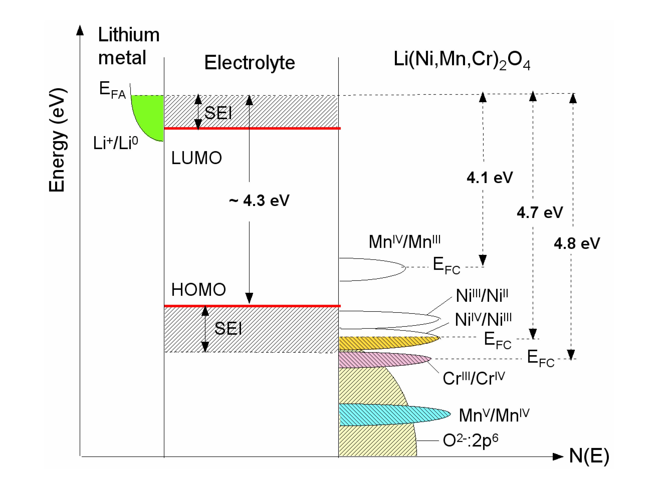
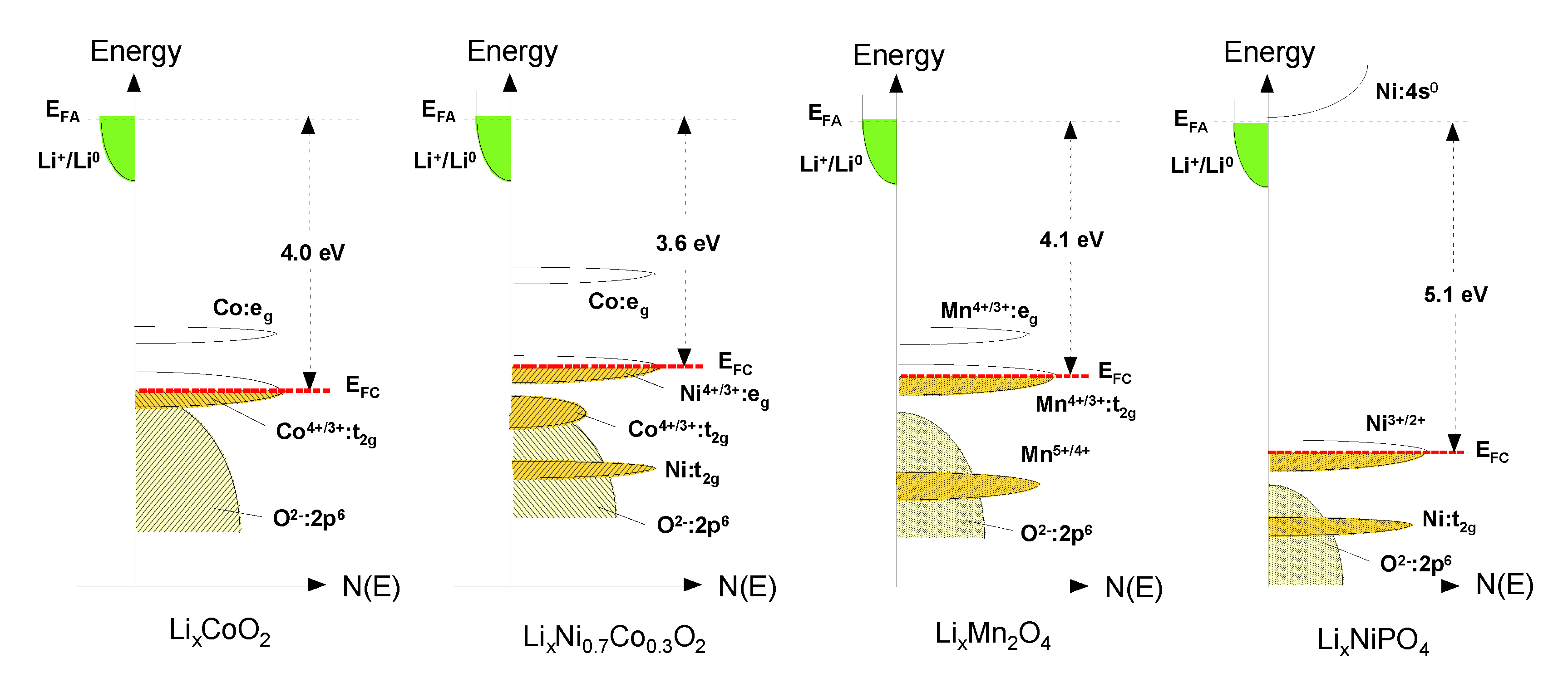
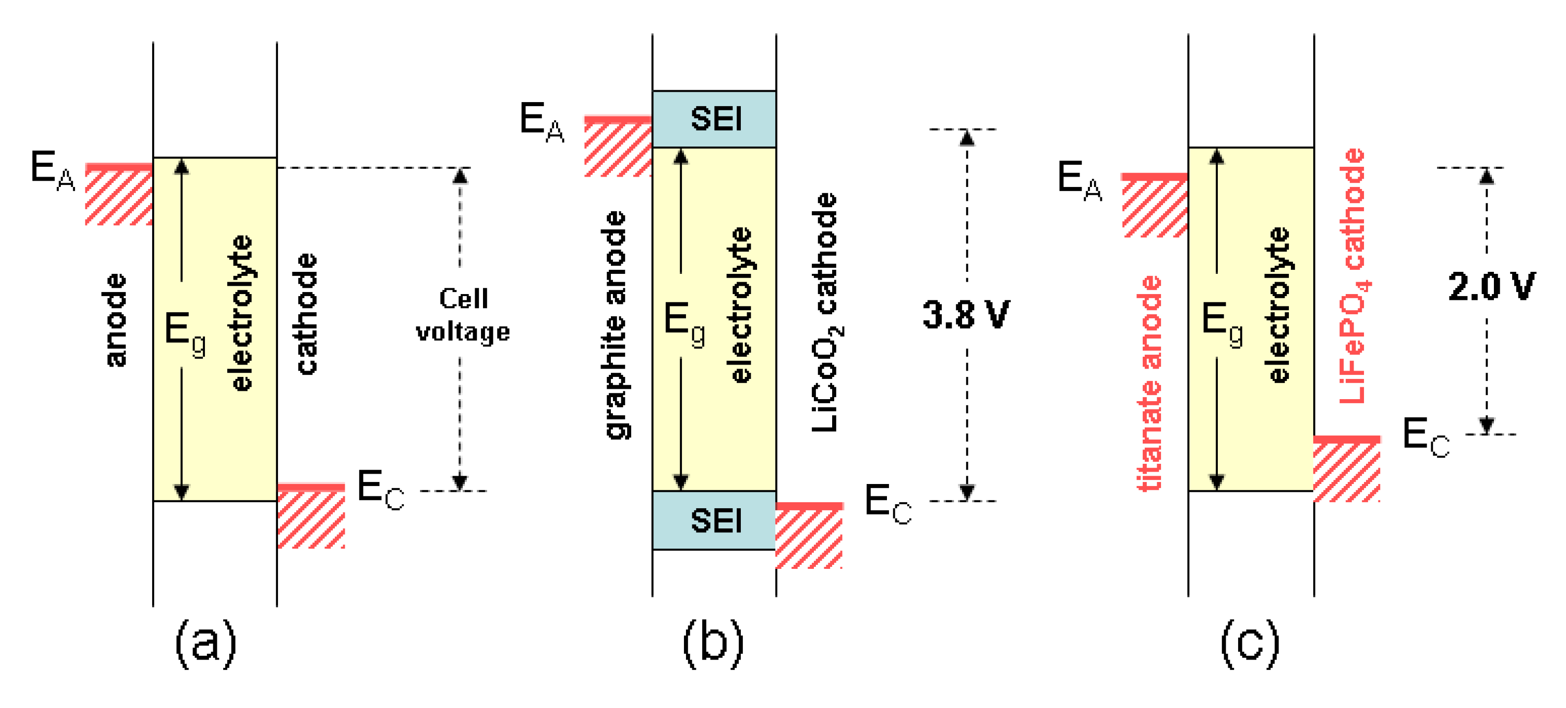
2. The Cell Potential (Goodenough Diagram)

The major contribution to the changes of the chemical potential during the intercalation process directly gives the open-circuit voltage of the battery such as
eVoc = μLi(C) −μLi(A) = ∆μe + ∆μLi+
in which the chemical potential of the exchanged Li-atoms in anode (A) and cathode (C) is conceptually divided to the involved occupation of sites by Li+-ions and the valence electronic density of states (DOS) by electrons. The charge compensation of exchanged Li+-ions is compensated by redox reaction within the electrode, which leads to a modified occupation of electronic states.
For a given redox couple, the potential of an intercalation electrode considered as solution of guest A in the host lattice <H> is provided by the classical thermodynamic law
Inorganics 02 00132 i001
where ∆G denotes the variation in the Gibbs energy of the system, x is the composition, z the number of electrons involved and F the Faraday’s constant. V(x) is thus the electrode potential as a function of the composition x in <AxH> [10].
Figure 1. Schematic diagram showing the electronic density of states and Fermi energies for an oxide-based electrode (LixNi0.5−yMn1.5−yCr2yO4 spinelmaterial). The Li permeable solid electrolyte interface (SEI) layer formed on the electrode surface preserves the overall reversible reaction.
Inorganics 02 00132 g001
The open-circuit energy diagram of a lithium battery (see Figure 1) has been discussed by Goodenough et al. [11,12]. If the active transition-metal cation contains a localized d-electron manifold, the manifold acts as a redox couple, e.g., Ni2+/4+ in LiNi1.5Mn0.5O4 (LNM). Successive redox couples are separated by an on-site effective Coulomb correlation energy U that can be large when augmented by either a crystal-field splitting or an intra-atomic exchange splitting [13]. However, when the Fermi energy EFC of the cathode material approaches the top of the anion p bands of the host, the p-d covalent mixing may transform the correlated d electrons at EFC into band electrons occupying one-electron states [11,14]. In the absence of a crystal-field splitting of the d orbitals at EFC, which is the case for Ni(IV) to Ni(II), the one-electron states are not separated by any on-site energy U and there is no step in the voltage of the battery. EFC is moved from one formal valence state to another upon the reduction or oxidation of the host.

3. Crystal Structure and Electronic Properties

The crystal structures of the three classes of Li-insertion compounds are shown in Figure 2. Their classification corresponds to the ion diffusion pathways and activation energy that govern Li-ion transport within the electrode materials [10]. Archetypes are the two-dimensional Li[M]O2 with M = Co, Ni, (NixCo1−x) or (NixMnyCoz), the three-dimensional Li[X]2O4 with X = Mn, (Mn1−y/2Liy/2) or (Mn3/4Ni1/4) and uni-dimensional Li[M']PO4 with M' = Fe, Mn, Ni, Co or (FeyMn1−y).
Figure 2. Crystal structure of the three lithium-insertion compounds in which the Li+ ions are mobile through the 2-D (layered), 3-D (spinel) and 1-D (olivine) frameworks.
Inorganics 02 00132 g002

3.1. Layered Compounds

Li[M]O2 (M = Co, Ni) oxides are isostructural to the layered α-NaFeO2 (space group R3m, No. 166) with the oxygen ions close-packed in a cubic arrangement and the TM and Li ions occupying the octahedral sites of alternating layers with an ABCABC… stacking sequence called “O3-type” structure (Figure 2). In LiCoO2, the cobalt is trivalent in the electronic configuration (t2g)6(eg)0, i.e., in the low-spin state (S = 0). However, LCO adopts the rhombohedral symmetry in the high temperature form, with Li in 3a, Ni in 3b and O in 6c sites. The unit-cell of the hexagonal setting contains three formula units. During the cycling of a lithium cell, the Li+ ions are reversibly removed from and incorporated into this framework creating or annihilating vacancies within the lithium planes as shown in Figure 2. These vacancies can indirectly drive electronic transitions in LCO or can organize the formation of ordered Li-vacancy structures on a triangular lattice of sites. Note that the low-temperature form (LT-LCO) adopts the spinel lattice with the cubic symmetry (S.G. Fd3m) [15,16]. A lithium ordering and stacking sequences leading to an equivalent environment for all Co ions is preferred in order to achieve a maximum of charge delocalisation and to minimize the energy. In LixCoO2, no coupling between Co:eg and Li:2s states occurs and the lowest-energy is reached in the interplanar stacking that leads to as many equivalent Co sites as possible. This is consistent with a Co+3/+4 tendency for charge delocalization at x = 0.5. In Li0.5CoO2, Co tends to have an intermediate oxidation state of +3.5 that induces a transition to a monoclinic structure [17]. Even worse, LiCoO2 suffers from the dissolution of the metal ion in the electrolyte that induces oxygen release, which becomes more important upon increasing the temperature. Thus, surface modification by metal-oxide coating such as ZrO2, Al2O3, TiO2, etc. was demonstrated being an effective strategy to avoid the cathode breakdown [18,19].
LiNiO2 (LNO) is isostructural with LiCoO2 and has the O3-type-oxygen packing shown in Figure 2. The Ni3+/4+ couple with high lithium chemical potential provides a high cell voltage of ca. 4 V like LCO. However, LNO suffers from a few drawbacks: (i) difficulty to synthesize LiNiO2 with all the nickel ions in the Ni3+ valence state and distributed in a perfectly ordered phase without a mixing of Li+ and Ni3+ ions in the lithium plane; Li1−zNi1+zO2 illustrates better the chemistry of this compound. (ii) Jahn-Teller distortion (tetragonal structural distortion) associated with the low spin Ni3+:d7 (t2g6eg1) ion. (iii) Irreversible phase transitions occurring during the charge-discharge process. (iv) Exothermic release of oxygen at elevated temperatures and safety concerns in the charged state [20]. As a result, LiNiO2 is not a promising material for commercial lithium-ion cells. However, mixed LiNi1yCoyO2 phases allow overcoming the main drawbacks exhibited by both LiCoO2 and LiNiO2 oxides [21,22,23]. For example, the solid solutions LiNi0.85Co0.15O2 and LiNi0.80Co0.15Al0.05O2 have been shown to exhibit attractive electrochemical properties with reversible capacity of ~180 mAh g−1 and excellent cyclability [24].

3.2. LiMn2O4 (LMO)

LiMn2O4 belongs to the A[B2]O4 spinel-type structure and crystallizes in the Fd3m space group (Oh7 factor group) with the cubic lattice parameter a = 8.239 Å [25]. The cubic spinel LiMn2O4 structure is described with the Mn and Li cations on the 16d and 8a sites, respectively, and the oxygen ions located on the 32e sites form a nearly ideal cubic close-packed (ccp) sublattice. Half of the octahedral interstices are occupied by the Mn ions forming a three-dimensional framework of edge-sharing MnO6 octahedra. Lithium ions occupy tetrahedral sites, which share common faces with four neighboring empty octahedral sites at the 16c position (Figure 2). This lattice offers a three-dimensional network of transport paths 16c-8a-16c through which lithium ions diffuse during insertion/deinsertion reactions [3,4].
The understanding of the LMO spinel from the standpoint of solid-state chemistry must take into account the presence of oxygen vacancies revealed by neutron diffraction measurements, and is subject to debate. Two structure models were proposed for the “oxygen vacancy” phase: vacancy at the oxygen site corresponding to the formula LiMn2O4−δ, and excess cations at the interstitial site with the formula Li1+xMn2+yO4 [26].

3.3. LiNi0.5Mn1.5O4 (LNM)

Substitution of 25% Ni for Mn in LiMn2O4 spinel has been chosen because this composition implies that Mn is in the 4+ valence, thus avoiding the Jahn-Teller (JT) distortion associated to Mn3+. Therefore, the electrochemical activity is only due to the oxidation/reduction of Ni2+ ions leading transfer of 2e per Ni ion. LiNi0.5Mn1.5O4 crystallizes in two possible crystallographic structures according the cationic sublattice: the face-centred spinel (S.G. Fd3m) named as “disordered spinel” and the simple cubic phase (S.G. P4332) named as “ordered spinel”. The cation distribution in the P4332 symmetry is then Li on 8c, Ni on 4b, Mn on 12d, and O(1) and O(2) oxygen ions occupy the 24e and 8c Wyckoff positions, respectively. The net result is thus a significant optimisation of space occupation leading to a reduced unit cell volume. It has been pointed out that phase-pure LNM is difficult to synthesize because impurities such as NiO and/or LiyNi1yO usually exist [27]. The partial replacement of Ni and Mn by Cr in LiNi0.5yMn1.5yCr2yO4 is an effective way to alleviate the problem of oxygen loss generating Mn3+ ions in the LNM framework and a voltage plateau at ca. 4 V vs. Li0/Li+. Thus, it has been demonstrated that the Cr-doping stabilizes the lattice without impacting the capacity significantly, but it decreases the energy density [28].

3.4. Olivine LiFePO4 (LFP)

The crystal structure of LiFePO4 materials has been studied by several authors [29,30,31]. As a member of the olivine family, LFP crystallizes in the orthorhombic system (Pnma space group, No. 62). It consists of a distorted hexagonal close-packed (hcp) oxygen framework containing Li and Fe located in half the octahedral sites and P ions in one-eighth of the tetrahedral sites. The FeO6 octahedra, however, are distorted, lowering the regular octahedral Oh to the Cs symmetry. This structure illustrated in Figure 2 shows the channels via which the lithium ions can be removed. Corner-shared FeO6 octahedra are linked together in the bc-plane, while LiO6 octahedra form edge-sharing chains along the b-axis. The tetrahedral PO4 groups bridge neighboring layers of FeO6 octahedra by sharing a common edge with one FeO6 octahedra and two edges with LiO6 octahedra.
The LiFePO4 structure consists in three non-equivalent O sites. Most of the atoms of the olivine structure occupy the 4c Wyckoff position except O(3) which lies in the general 8d position and Li+ ions occupying only the 4a Wyckoff position (M1 site on an inversion center). The Fe magnetic ions are in the divalent Fe2+ state and occupy only the 4c Wyckoff position (M2 site in a mirror plane), i.e., the center of the FeO6 units. As a consequence, Fe is distributed so as to form FeO6 octahedra isolated from each other in TeOc2 layers perpendicular to the (001)-hexagonal direction [22]. In addition, the lattice has a strong two-dimensional character, since above a TeOc2 layer comes another one vertical to the previous one, to build (100) layers of FeO6 octahedra sharing corners, and mixed layers of LiO6 octahedra and PO4 octahedra. The lithium iron phosphate material differs from the primary mineral triphylite Li(Mn,Fe)PO4 by the fact that triphylite is only rich in iron, with some manganese ions also in the M2 site [32]. However, while the triphylite is a naturally occurring mineral, LiFePO4 is an artificial product.
The energy diagrams vs. DOS showing the relative Fermi level of the Li-insertion compounds described in this Section are shown in Figure 3: the Co4+/3+ redox couple for LiCoO2, the Ni4+/3+ redox couple for LiNi0.8Co0.2O2, the Mn4+/3+ redox couple for LiMn2O4 and the Ni3+/2+ redox couple for LiNiPO4. Also, the cell voltage Voc determined by the energies involved in both the electron transfer and the Li+ transfer highlights the concept of rechargeable lithium batteries. While the energy involved in electron transfer is related to the work functions of the cathode and anode, the energy involved in Li+ transfer is determined by the crystal structure and the coordination geometry of the site into/from which Li+ ions are inserted/extracted. The stabilization of the higher oxidation state is essential to maximize the cell voltage and the energy density. The location of O:2p energy and a larger raising of the Mn+:d energies due to a larger Madelung energy make the higher valent states accessible in oxides. That is why transition-metal oxide hosts were pursued as positive electrode candidates for Li-ion secondary batteries [13].
Figure 3. Comparison of the energy vs. density of states showing the relative Fermi level of the Co4+/3+ redox couple for LiCoO2, the Ni4+/3+ redox couple for LiNi0.8Co0.2O2, the Mn4+/3+ redox couple for LiMn2O4 and the Ni3+/2+ redox couple for LiNiPO4.
Inorganics 02 00132 g003

4. Electrochemical Properties and Phase Diagram

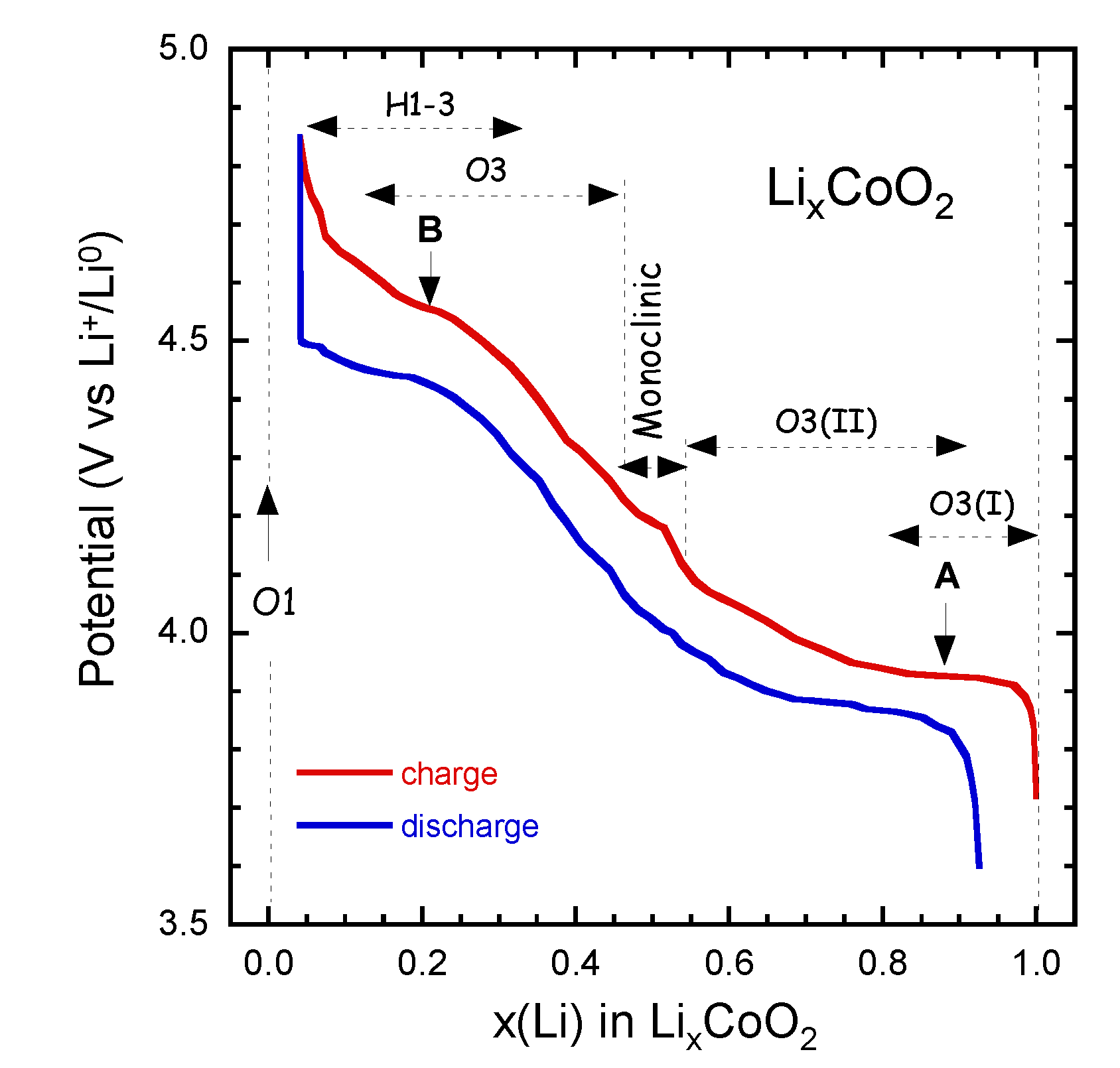
4.1. Lithium Cobaltate (LCO)

LixCoO2 used as prototype positive electrode in LIBs. Charge-discharge curves LixCoO2 at C/24 rate in the range 3.6–4.85 V vs. Li0/Li+ are shown in Figure 4. The sequence of the several phases is indicated as x varies from 1.0–0.05. LiCoO2 has shown degradation and fatigue during electrochemical cycling. The change can be interpreted as an increasing energetic overlap of the Co:3d and O:2p states and a change in the orbital of Co and oxygen wave functions. For 1.0 ≥ x ≥ 0.5, the DOS nearly does not change and the charge compensation with Li extraction leads to a removal of electrons from the Co:3dt2g derived states with the Fermi level moving downwards (Figure 3).
Laubach et al. [33] have shown that the valence band (VB) is mainly unchanged with a slight shift of the top of the VB to lower binding energies, which implies a shift of EFC that provokes the removal of d-electrons due to the change of the oxidation state from Co3+ to Co4+. For x < 0.5, a clear increase in hybridisation occurs between the Co:3d and O:2p states associated with a reduction of the (CoO6)-slab distances evidenced by the reduction of the c-axis lattice parameter. As a consequence, the charge compensation of the delithiation leads to a removal of electrons from Co-O:d-p hybrid states, which translates to a partial oxidation of the O2 ions [34,35,36].
Figure 4. Charge-discharge curves LixCoO2 at C/24 rate in the range 3.6–4.85 V vs. Li0/Li+. The sequence of the several phases is indicated as x varies from 1.0–0.05.
Inorganics 02 00132 g004

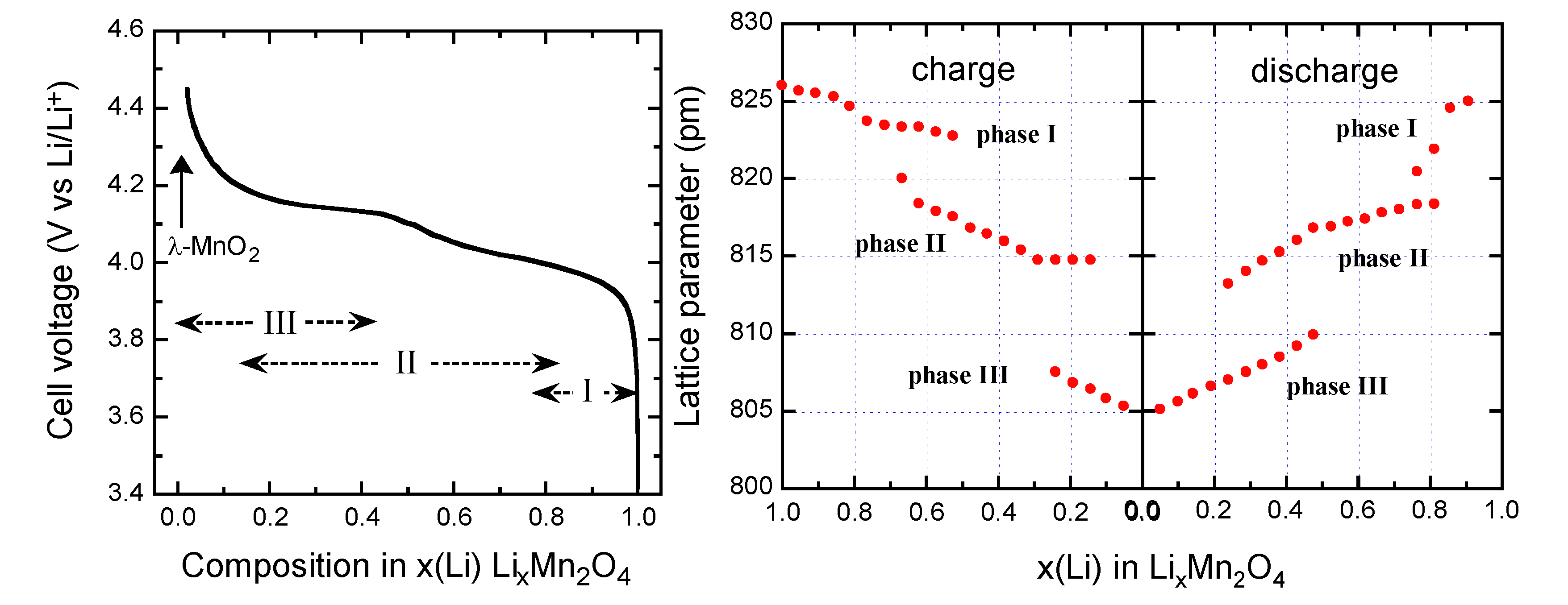
4.2. Lithium Manganese Spinel (LMO)

Manganese is five times cheaper than cobalt and is found in abundance in nature. The spinel LiMn2O4 has a strong edge-shared [Mn2]O4 octahedral lattice and exhibits good structural stability during the charge-discharge process. LiMn2O4 spinels have shown a lack of robustness in their cycle life and irreversible loss of capacity that becomes rapid at elevated temperatures [37].
The electrochemical data demonstrate that Li+ ions are extracted from the tetrahedral sites of the LixMn2O4 spinel structure at approximately 4 V in a two-stage process, separated by only 150 mV [38] at a composition Li0.5Mn2O4 (Figure 5). At x = 0, the λ-MnO2 phase (λ-γ[Mn2]O4 in the spinel notation) is formed. The two-step process is due to ordering of the lithium ions on one-half of the tetrahedral 8a sites. In the spinel LMO, generally, Li at tetrahedral 8a site moves to vacant octahedral 16c site, and the 3-D 8a-16c-8a-16c network provides an energetically favourable pathway for the rapid diffusion of lithium in and out of the structure during discharge and charge, respectively.
Lithium insertion into LMO occurs at approximately 3 V. During this process, Li+ ions are inserted into the octahedral 16c sites of the spinel structure. Since the 16c octahedra share faces with the 8a tetrahedra, electrostatic interactions between the Li+ ions on these two sets of sites cause an immediate displacement of the tetrahedral-site Li+ ions into neighboring vacant 16c octahedral sites. The reaction results in a first-order transition to Li2Mn2O4 with a stoichiometric rock-salt composition on the surface of the electrode particle. The electrochemical process at 3 V is thus a two-phase reaction. During discharge, a reaction front of Li2Mn2O4 moves progressively from the surface of the LiMn2O4 particle into the bulk. At 3 V, the Li insertion is accompanied by a severe Jahn-Teller distortion as a result of an increased concentration of Mn3+:d4 ions in the Mn2O4 spine1 lattice, which reduces the crystal symmetry from cubic (c/a = 1.0) to tetragonal symmetry (c/a = 1.16) that results in a 16% increase in the c/a ratio detrimental to the electrochemical cycling.
Figure 5. Voltage profile of a Li//LiMn2O4 cell discharged at C/24 rate with LMO material synthesized at 700 °C (left).Variation of the lattice parameters as a function of the Li content x during the charge/discharge in LMO cathode (right).
Inorganics 02 00132 g005
Xia et al. [39] showed by in situ X-ray diffraction that a two-phase structure coexists in the high-voltage region for LMO that persists during Li-ion insertion/extraction at low temperatures during cycling. Dai et al. [38] developed a mathematical model for the capacity fade of a LMO electrode by including the acid attack on the active material and the solid electrolyte interphase (SEI) film formation on the LMO particle surface. The acid generated by the LiPF6 and the solvent decompositions are coupled to the Mn dissolution. The decrease of the Li ion diffusion coefficient is involved as another contribution to the capacity fade, which is caused by the passive film formation on the active material surface.
Several reasons have been proposed for the capacity loss of Li//LixMn2O4 cells in the 4-V region as follows [40,41].
(i) The major drawback is the disproportionation of Mn3+ at the particle surface in the presence of trace amounts of protons (acid attack) into Mn2+ and Mn4+
2Mn3+(solid) → Mn4+(solid) + Mn2+(solution)
resulting in a leaching out of Mn2+ ions from the positive electrode framework into the electrolyte [41]. Xia et al. [39] reported that chemical analytical results indicated that the capacity loss caused by the simple dissolution of Mn3+ accounted for only 23% and 34% of the overall capacity losses cycling at room temperature and 50 °C, respectively. The appropriate method to reduce capacity fade of LMO is surface coating of the particles to prevent the Mn2+ dissolution by a thin layer of inorganic material such as Al2O3 [42], zirconia [43], MgO [44], Li2O-B2O3 glass [45], AlF3 [46], etc. The use of surface treatment is an effective way to improve the elevated temperature storage properties of LMN spinels. This has been done by creating a protective barrier layer between the liquid electrolyte and the particle surface showing the importance of controlling the surface chemistry. Another way to avoid this problem has been to choose chemical composition such that Mn remains inactive in the 4+ valence state; this is the case for LiNi1/3Mn1/3Co1/3O2 and LiNi1/2Mn3/2O4.
(ii) The instability of the delithiated spinel structure by oxygen loss in organic electrolyte solvents in the end of the charge.
(iii) The onset of a Jahn-Teller effect at the end of discharge (particularly at high current density). Under dynamic, non-equilibrium conditions above 3 V, it has been proposed that some crystallites can be more lithiated than others, thereby driving the composition of the electrode surface into a Mn3+-rich Li1+xMn2O4 region [47,48].
Moreover, the specific capacity of spinel LiMn2O4 is limited to <120 mAh g1 around 4.1 V vs. Li0/Li+, which corresponds to the extraction of 0.8 Li per formula unit. It has also pointed out that additional Li could be inserted into the empty octahedral holes of the spinel framework at a potential of ~3 V vs. Li0/Li+ accompanied by a structural change from cubic to tetragonal symmetry due to the Jahn-Teller distortion associated with the high-spin Mn3+ (t2g3eg1) ions inducing a huge volume change and severe capacity fade. Evidence of structural fatigue has been detected by high-resolution electron diffraction and imaging, at the surface of discharged LixMn2O4 spinel electrodes in Li//LixMn2O4 cells [49]. Under non-equilibrium conditions, domains of tetragonal Li2Mn2O4 coexist with cubic LiMn2O4, even at 500 mV above the voltage expected for the onset of the tetragonal phase. The presence of Li2Mn2O4 on the particle surface may contribute to the capacity fade observed during cycling of Li//LixMn2O4 cells, due to the loss of particle-to-particle contact at the cubic-LiMn2O4/tetragonal-Li2Mn2O4 interface in discharge state. In situ XRD has been used to study the LixMn2O4 (0 ≤ x ≤ 1) cathode materials during extraction and insertion of Li+ ions.
Three-phase behavior is observed during the first charge-discharge cycle in the 4-V region (Figure 5). The voltage profile exhibits two plateaus at 4.05 and 4.15 V corresponding to two-phase systems induced by three cubic phases. LiMn2O4 is a small-polaron semiconductor, electronic conduction occurring via hopping of electrons between eg orbitals on adjacent Mn3+/Mn4+ cations. Thus, the gradual removal of Li+ ions from the structure during deintercalation should result in a decrease in the number of mobile electrons throughout the whole solid [50].

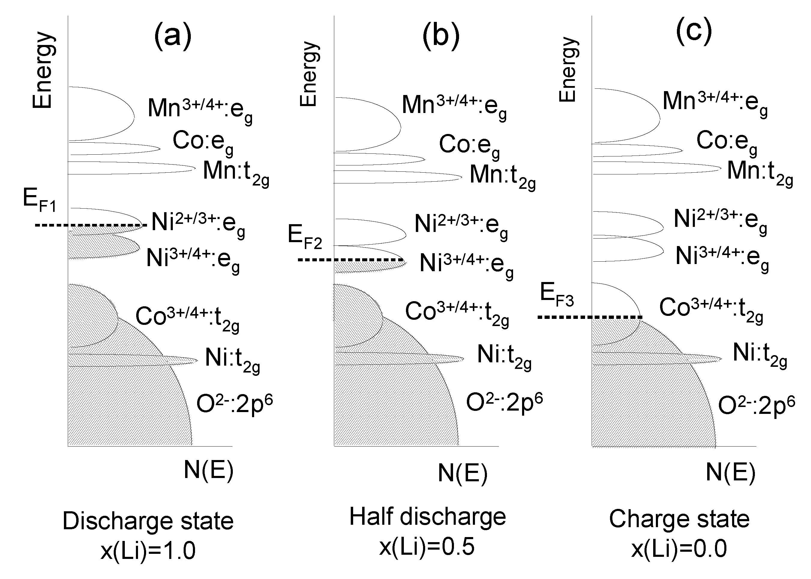
4.3. Lithium Mn-Ni-Co Oxides

The layered LiNiyMnyCo1−2yO2 (NMC) compounds with a hexagonal single-phase α-NaFeO2-type structure have received great attention as 4V-electrode materials to replace LiCoO2 in Li-ion batteries, owing to its better stability during cycling even at elevated temperature, higher reversible capacity and milder thermal stability at charged state [51]. Its reversible capacity was measured to be 160 mAh g−1 in the cut-off range of 2.5–4.4 V and 200 mAh g−1 in that of 2.8–4.6 V [52]. The main problem that still needs to be solved for such applications of NMC is the cation mixing between nickel and lithium ions, since the ionic radius of Ni2+ (0.69 Å) is close to that of Li+ (0.76 Å). The cation mixing between Li+ and Ni2+ ions on the crystallographic (3b) sites of the NMC lattice is known to deteriorate their electrochemical performance. Rietveld refinement of the XRD data have demonstrated the validity of the structural model [Li1−δNiδ]3b[LiδNix−δMnyCo1−xy]3aO2 (see detail in ref. [53]). Within a rigid-band model, the calculation of the relative position of the Fermi level and the O:2p band with respect to the Ni4+/3+ and Co4+/3+ redox couples for LiNiyMnyCo12yO2 as a function of x(Li) during the charge shows that in of 2.8–4.6 V potential region the NMC electrodes are more stable than LCO ones (Figure 6).

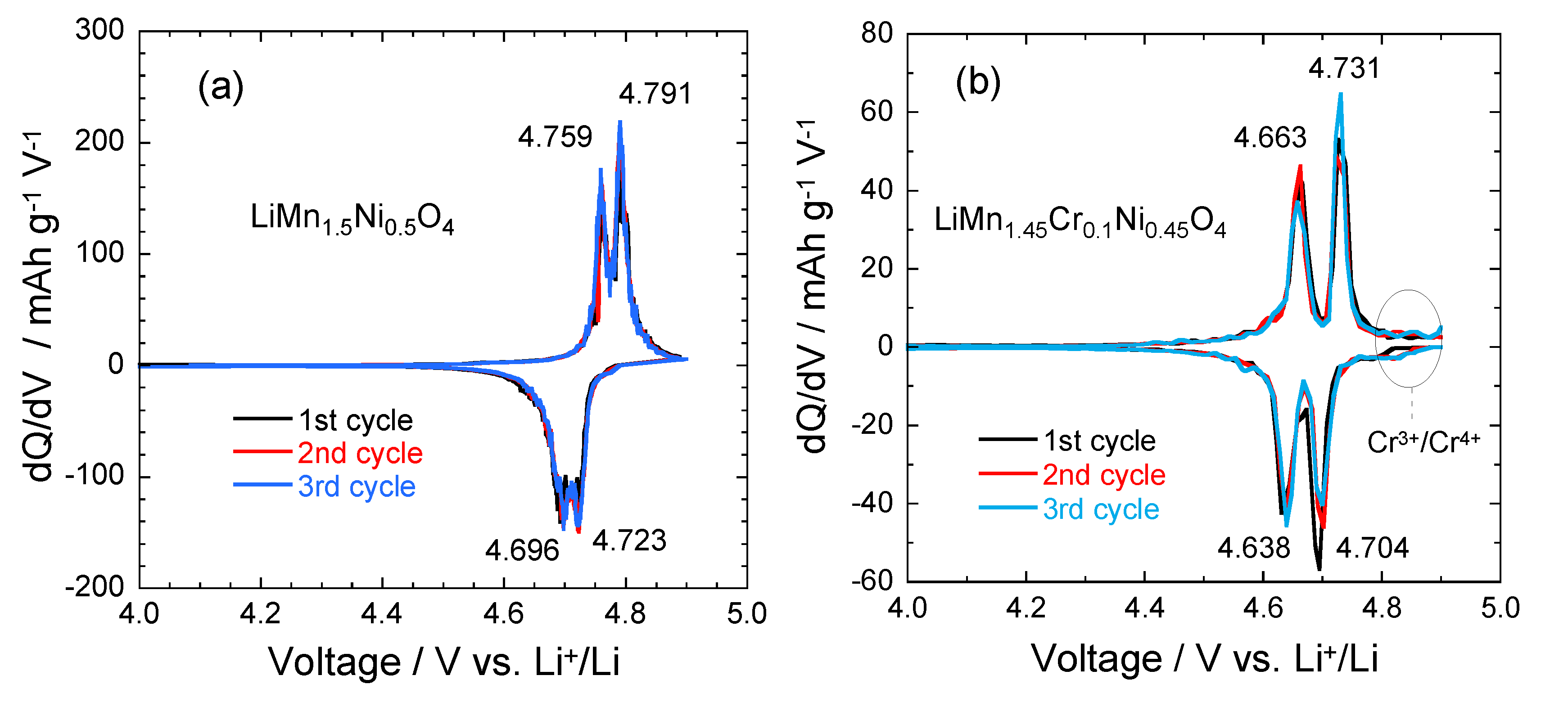
4.4. LMN and Doped-LMN Electrodes

The partial substitution of metal cations for the Mn forming the LiMn2−yMyO4 and LiMn1.5−yNi0.5−yM2yO4 solid solutions (with M = Ni, Cu, Cr) is a strategy to improve significantly the electrochemical cycling of LiMn2O4 materials, but at the expense of a decrease in the initial capacity within the useful voltage window, i.e., below 4.4 V. Such a successful result is due to the reduction of the concentration of the Mn3+ JT ions that provokes the tetragonal phase transition in the 3-V region. As an example, the early work of Ein-Eli and Howard [54] showed by cyclic voltammetry measurements that Cu substitution for Mn in LMO exhibited two discharge regimes, at 4.1 and 4.9 V vs. the Li0/Li+ couple. The discharge capacity of LiCuxIICuyIIIMn[2−(x+y)]III,IVO4 was 71 mAh g−1 (97% of theoretical). Investigations have shown that the composition LMN possesses specific electrochemical characteristics such as a high capacity of 130–140 mAh g−1 associated to a high-voltage plateau at 4.7 V [55].
Figure 6. The energy vs. density of states showing the relative Fermi level of the Ni4+/3+ and Co4+/3+ redox couples for LixNiyMnyCo12yO2 during the charge, for three states of charge determined by the Li concentration x; (a) x = 1; (b) x = 0.5; (c) x = 0.
Inorganics 02 00132 g006
The electrochemical features show that the characteristic 4.1 V Mn3+/4+ redox couple is always observed in the pristine or metal-doped LMN electrodes as a result of oxygen loss at high-temperature synthesis. However, no obvious 4.1 V step is detected in LiMn1.45Ni0.45Cr0.1O4 spinel, confirming that most of the residual Mn3+ ions have been re-oxidized to Mn4+ after re-annealing at 600 °C in agreement with the analysis of magnetic properties [26]. This is also consistent with the Rietveld refinement results. In order to understand the difference in the electrochemical properties of these electrode materials, Figure 7 compares the incremental capacity curves, dQ/dV vs. V graphs. Removal of Li from the tetrahedral sites of the spinel LMN framework initially probes the oxidation reaction of Ni2+/3+ just below 4.7 V (typically ~4.69 V) for the disordered Fd3m and above 4.7 V (typically ~4.72 V) for the ordered P4332 spinels [56]. Ordering of the Ni and Mn raises by ~0.02 eV the V(x) profile of LMN. From Figure 7, two anodic peaks at 4.663 and 4.731 V plus two cathodic peaks at 4.638 and 4.704 V are observed for the Cr-doped LMN, which is in agreement with two voltage plateaus for disordered LMN. Kim et al. suggested that as the crystallographic structure changed from Fd3m to P4332, the voltage gaps between the two plateaus became narrower at around 4.75 V and resulted in a flatter voltage profile [57].

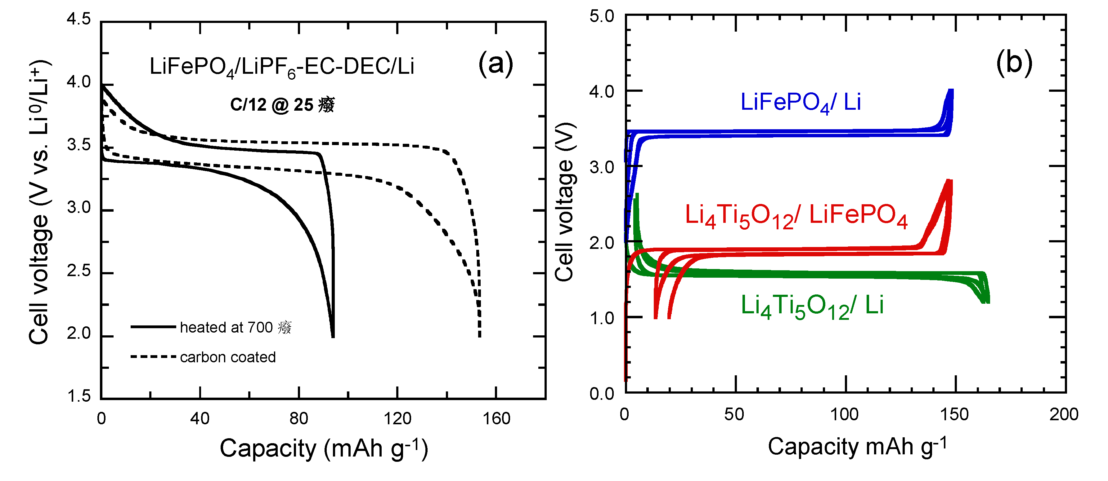
4.5. Lithium Iron Phosphate (LiFePO4)

With theoretical specific capacity 170 mAh g−1 at moderate current densities, the phospho-olivine LiFePO4 (LFP) is considered as potential positive electrode material for use in lithium rechargeable cells; it is inexpensive and not toxic, two determinant advantages with respect to cobalt-oxide-based materials for large-scaled applications such as hybrid electric vehicles (HEV). Nevertheless, the low electronic conductivity (σe < 10−9 S cm−1) and the low diffusion coefficient of Li+ ion ( Inorganics 02 00132 i002 10−14 cm2 s−1) of LFP may result in losses in capacity during high-rate discharge. However, the reduction of the LFP particles to the nanosize provides short Li+-ion diffusion paths within the positive electrode. In addition, the synthesis of carbon-coated LFP remarkably enhances the electrical conduction between particles ensuring high rate capability and preventing particles agglomeration [58,59,60].
Figure 7. Differential capacity curves, dQ/dV vs. V, of the (a) LMN and (b) Cr-doped LMN. The values at the peaks are given in volt [28].
Inorganics 02 00132 g007
Electrochemical extraction of Li from LiFePO4 gives (Fe2+/Fe3+) redox potential at ca. 3.45 V vs. Li0/Li+. A small but first-order displacive structural change of the framework gives a two-phase separation over most of the solid-solution range 0 < x < l for LixFePO4 and therefore a flat V-x curve. A reversible capacity ≈160 mAh g−1 is delivered by the nano-structured cathode particles coated with carbon. This result is attributed to the high quality of the “optimized” LiFePO4, impurity-free materials used as positive electrodes. Figure 8a presents the voltage profiles of LiFePO4//Li cells as a function of the preparation of the electrode material. These graphs show that without carbon coating, the specific capacity is lower than 100 mAh g−1, while a 3-nm thick carbon film deposited onto 500-nm sized LFP particle enhances the discharge capacity to 141 mAh g−1 at C/12 rate [61,62].
The electrochemical performance of optimized LFP and LTO electrode materials has been tested separately in half cell with respect to Li metal anode, using the same usual electrolyte 1 mol L−1 LiPF6 in ethlene carbonate (EC) and diethylene carbonate (DEC) [62,63]. The voltage vs. capacity curves recorded under such conditions at 25 °C are reported in Figure 8b at low C-rate C/24 to approach thermodynamic equilibrium together with the potential-capacity curve of the LTO//LFP lithium-ion battery. The voltage window is 2–4 V for LiFePO4, 1.2–2.5 V for Li4Ti5O12. Note in this figure (and the following ones), we have kept the conventional rule, i.e., the capacity is in mAh per gram of the active element of the cathode. That is the reason why the maximum capacity for the LFP//Li and LFP//LTO cells are the same. For LFP//Li, the first coulombic efficiency is 100% and the reversible capacity is 148 mAh g−1. For LTO, the first coulombic efficiency is 98% and the reversible capacity is 157 mAh g‑1. The well-known plateaus at 3.4 and 1.55 V are characteristics of the topotactic insertion/deinsertion of lithium in the two-phase systems LiFePO4-FePO4 and Li4Ti5O12-Li7Ti5O12, respectively [64].
Figure 8. (a) Electrochemical performance of the LiFePO4//Li coin cell operating at room temperature before and after carbon coating. Charge-discharge cycling was conducted at the C/12 rate. (b) Voltage-capacity cycle for LiFePO4//Li, Li4Ti5O12//Li and Li-ion cell LiFePO4//Li4Ti5O12 at C/24 rate [62]. The capacity is in mAh per gram of the positive electrode element (LiFePO4, Li4Ti5O12 and LiFePO4, respectively). The larger hysteresis in the LiFePO4//Li4Ti5O12 cell comes from the fact that the cell in that case was a button cell instead of the more elaborate 18650-cell, but the plateau at 1.9 V is well observed. All the cells used 1 molL−1 LiPF6 in EC:DEC (1:1) as electrolyte.
Inorganics 02 00132 g008

5. Safety Issues

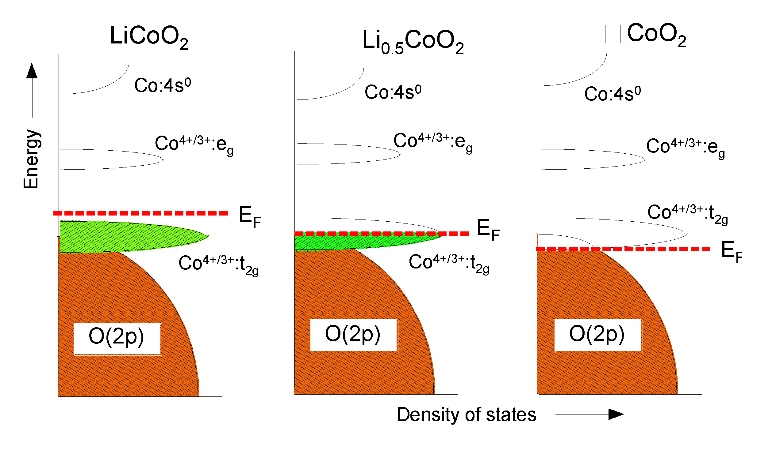
5.1. Loss of Oxygen in LixCoO2

The LixCoO2 cathodes are known to cycle well for x > 0.5 and, therefore, no oxygen loss may occur in electrochemical cells. The observation of the beginning of oxygen loss at a slightly higher Li content x ≈ 0.45 could be due to a rapid and deeper extraction of lithium on the surface although the average lithium content is >0.5, which may result in overall oxygen content slightly less than 2 for 0.5 ≤ x ≤ 0.45. The band diagrams given in Figure 9 show the differences in the chemical instability with respect to oxygen loss due to the overlapping of the Co4+/3+:t2g band with the O:2p orbitals.
Chemical analysis of electrochemically charged Li1−xCoO2 samples indicates that the oxygen loss occurs below lithium content x = 0.5 [65]. The results suggest that the cobalt oxide system is intrinsically prone to lose oxygen for x < 0.5 in the Li-ion cells. The loss of oxygen from the lattice in the Li1−xCoO2 system may be one of the reasons for the limited capacity (140 mAh g‑1) leading to capacity fade. On the other hand, the absence of oxygen loss for 0.7 ≤ x ≤ 0 in the LixNi0.85Co0.15O2 system as well as the appearance of the second phase at a much lower lithium content x < 0.77 permit the realization of a higher capacity, ca. 180 mAh g−1.

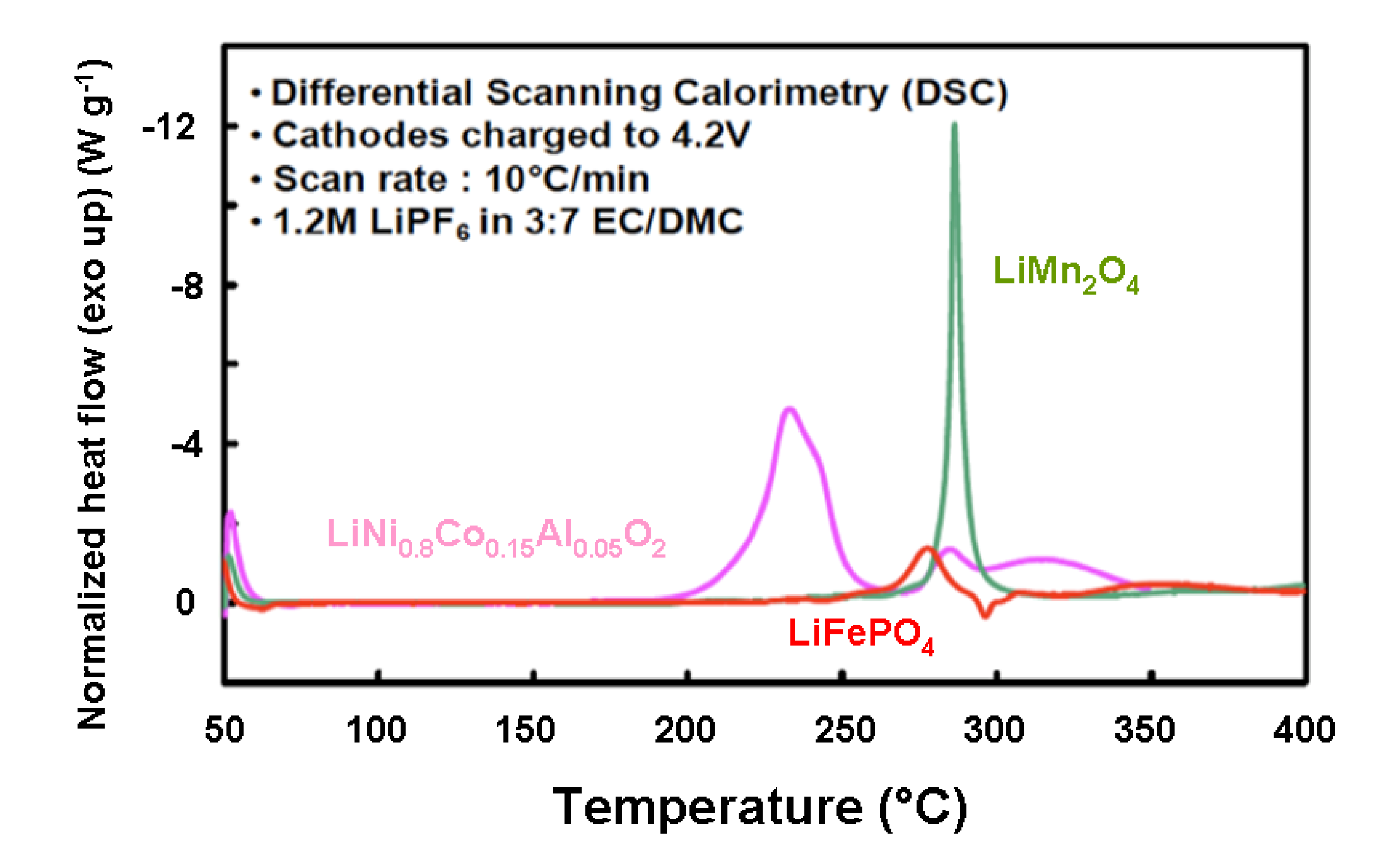
5.2. Comparative Safety Issues

Thermal stability for lithium-insertion compounds use as positive electrodes in Li-ion batteries has been studied for C-LiFePO4, LiNi0.8Co0.15Al0.05O2, LiNi0.33Co0.33Mn0.33O2 and LiCoO2 [66]. Figure 10 shows differential scanning calorimetry (DSC) spectra of the overcharged spinel (LiMn2O4), layered (LiNi0.8Co0.15Al0.05O2) cathode and carbon-coated LiFePO4, all electrodes with traces of 1.2 mol L−1 LiPF6 in ethylene carbonate:ethyl-methyl carbonate (3:7), measured at a scan rate of 10 °C min−1 from 50–400 °C. We can observe that both spinel and olivine cathodes have delayed onset temperature by at least 70 °C with respect to the layered cathode. The layered cathode was found to be thermally unsafe, as this cathode undergoes its exothermic reaction with very large enthalpy (−941 J g−1) and the reaction is completed at much earlier temperature, lower than the onset temperature of spinel and olivine. Spinel cathode showed roughly half the exothermic reaction enthalpy (−439 J g−1), whereas carbon-coated olivine showed even lesser exothermic reaction enthalpy (−250 J g−1). The DSC results for layered, spinel and olivine positive electrodes are summarized in Table 2.
Figure 9. Change of the qualitative energy diagrams of LixCoO2 as a function of the lithium content. From left to right: x = 1, x = 0.5, x = 0.
Inorganics 02 00132 g009
Based on their previous experimental results, Bang et al. [67] proposed that a possible mechanism leading to the thermal runaway of the layered cathode consists of the following four steps as follows: Step (1): The first step involves a partial structural deformation of LixNi0.8Co0.15Al0.05O2 into disorder oxide (spinel-like structure) and liberation of small amount of oxygen from it as a result of this structural deformation. Step (2): This step entails the reaction of the oxygen produced in Step (1) with the ethylene carbonate due to its lower flash point of 150 °C
C3H4O3 + 2.5O2 → 3CO2 + 2H2O
The continuous reaction of the oxygen with EC and possibly EMC releases combustion heat in the system and raises the temperature, Step (3): The heat released in the above reaction further accelerates the structural deformation, which finally leads to complete structural collapse of the oxide
Li0.36Ni0.8Co0.15Al0.05O2 → 0.18Li2O + 0.8 NiO + 0.05Co3O4 + 0.025Al2O3 + 0.372O2
Finally, Step (4): The large amount of oxygen and heat produced in the above reaction helps the combustion of the remaining electrolyte (EC, EMC, and LiPF6) to produce thermal runaway
C3H4O3 + 2.5O2 → 3CO2 + 2H2O
C3H8O3 + 2.5O2 → 3CO2 + 2H2O
However, in LiFePO4, the phase transformation to FePO4 is considered to occur in Step (1) rather than structure disordering observed in a layered cathode. Step (2) is observed to the same extent found in layered cathode, whereas Step (3) is mostly prevented as the heat released from combustion of the solvents with O2 is used to maintain the FePO4 phase, hence the structural stability of the LiFePO4/FePO4 cathode. Again, the strong P-O covalent bonds in (PO4)3 polyanion found in LiFePO4 significantly reduce the rate of O2 release, thereby reducing the combustion step itself and causing no further damage to the cathode structure.
Figure 10. DSC spectra of over charged layered, spinel and olivine cathodes with traces of 1.2 mol L−1 LiPF6 in EC-EMC (3:7) electrolyte at 10 °C min−1 [66].
Inorganics 02 00132 g010
Table 2. Flow of enthalpy deduced from the DSC spectra of the fully delithiated and over charged carbon-coated LiFePO4 and the fully lithiated carbon-coated graphite that of the overcharged cathode elements investigated are reported in the three last columns.
Cathode materialOnset T (°C)Overall ∆H (J g−1)
LiNi0.8Co0.15Al0.05O2170−941
LiMn2O4264−439
LiFePO4245−250
Isothermal micro-calorimetry (IMC) measurements on LiFePO4 have shown that the cell temperature is raised to not more than 34 °C during charge and discharge at 0.5C rate, and DSC measurements showed that LiFePO4 is less reactive with electrolyte at high temperatures than spinel and layered cathodes. Moreover, fully lithiated graphite was observed to show more exothermic heat than LiFePO4 cathode itself, resulting from SEI layer decomposition. So, a fully charged cylindrical 18,650 cell using LiFePO4/graphite was tested in Accelerating Rate Calorimeter (ARC) to realize the overall combination of exothermic reaction heats of LiFePO4, graphite and electrolyte [66]. The simultaneous cell temperature and heater temperature and in-situ cell open-circuit potential recorded during the ARC test of the cell is reported in Figure 11. It shows that the cell was heated uniformly as the thermocouples placed on top, side and base of the heater indicated the same temperature during the course of the experiment, and the cell temperature also closely followed the heater temperature until any self-heat was released from the cell. Open-circuit potential remained constant around 3.3 V during this period. At a temperature of about 80 °C after 160 min from the start of the experiment, the cell started to show self-heat at a rate greater than 0.02 °C min−1. Once the self-heat is released from the cell and is sustained for more than 30 min, the heater begins to follow the cell temperature to the same rate of self-heat. Open-circuit potential also began to gradually drop due to the resistive heating of the cell. After 1455 min of testing, the cell temperature began to rise sharply at a temperature of 150 °C and open-circuit potential began to drop rapidly. This behavior of the cell was attributed to an internal short-circuit of the cell owing to the melting of the separator. At 1756 min of testing, the cell completely decomposed and the cell temperature completely shot off from that of the heater temperature by more than 80 °C; the cell voltage abruptly fell close to zero a few minutes later.
Figure 11. Cell temperature measured at side, top and base of the heater (the curves are superposed) and in-situ open-circuit potential chronological record of LiFePO4/C 18,650 cell subjected to an ARC test [66].
Inorganics 02 00132 g011

6. Concluding Remarks

The development of various lithium insertion compounds over the years has made lithium-ion batteries a commercial reality as listed in Table 3. The transition-metal oxides crystallizing in rock salt-based layer, spinel and olivine structures such as LixMO2 (M = Co, Ni, Ni1−yCoyO2), LiM'2O4 (M' = Mn, Ni1/4Mn3/4) and LiFePO4. These hosts having highly oxidized M4+/3+ and M3+/2+ redox couples emerge as the leading candidates for positive electrodes.
The principal challenges facing the development of suitable hosts with compatible anodes for the next generation Li-ion cells for either portable electronic or electric vehicles request several considerations: chemical and structural stabilities, capacity electrode, voltage, rate capability, service life and thermal safety. Long service life requires elimination of unwanted chemical reactions between electrode materials and the electrolyte. The good capacity retention over many charge-discharge cycles restricts the volume change vs. state of charge of the active electrode material. Safety is related to the flammability of the electrolyte, the rate of charge and/or discharge and the structural stability, i.e., absence of oxygen produced by the structural collapse of the cathode. Both the LiFePO4 cathode and the Li4Ti5O12 anode have demonstrated safe and rapid charge and discharge over many cycles. Their chemical potential is located within the electrolyte window (µCµA < Eg), which removes the requirement of a passivating SEI layer (Figure 12).
Table 3. Configuration of the three types of Li-ion cells related to their application. Positive electrodes are either layered (L), spinel (S) or olivine (O) frameworks.
ApplicationPositive electrodeNegative electrodeRemarks
High energyLiCoO2 (L) LiNi yCozM1−yzO2 (L) LiMn2O4 (S)Graphite, Si, SnO x, CoOx, FeOx, CuOx, NiOx, etc.M = Mn, Al, Cr named “LMO”
High powerLiMn2− yAlyO4+δ (S) LiNiyMnyCo2−yO2 (L) LiFePO4 (O)hard carbon, graphite Li4Ti5O12 (S)named “NMC” “LFP//LTO” cell
Long cycle lifeLiMn2− yAlyO4+δ (S) LiFePO4 (O) LiFe1−yMnyPO4 (O)Graphite Li4Ti5O12 (S) Li4Ti5O12 (S)named “LFP”
Figure 12. Schematic comparison between the LCO//graphite and the LFP//LTO cells. (a) Ideal batterywhere potentialEAEC < Eg, the voltage of thebatteryis equal to the energy difference V = ECEA; (b) The conventional graphite//LiCoO2Li-ion battery where EAEC > Eg; this cell works throughthe formation of theSEI; (c) The HQ-type LTO//LFP Li-ion battery where EAEC < Eg; this cell operateswithout the formation of the SEI.
Inorganics 02 00132 g012
Reducing the particle size or designing the architecture of the electrode material to the nanoscale level is one of the options abovementioned and can lead to improvement in the electrochemical performance. The reduced diffusion path length for Li+ ions and electrons increase particularly the rate of charge or discharge as the characteristic time, τ, is given by τ = L2/4π Inorganics 02 00132 i002, where L is the particle size and Inorganics 02 00132 i002 the diffusion coefficient of Li+ ion in the host lattice. As an example, for 2-µm LiFePO4 particles τ = 83 h, while decreasing the particle to 40 nm reduces τ to 13 s. The volume changes caused by Li+ insertion/extraction are better accommodated by nanosized particles due to faster strain relaxation. However, a few disadvantages are: (i) the need of surface coating for either minimizing the reaction at the electrode-electrolyte interface for LCO and LMO or enhanced the electrical contact between particles for LFP; (ii) the increase of the specific surface area of nanoparticles could enhance the rate reaction at the interfaces, especially for LCO material and (iii) the lower density of the electrode material, which reduces the volumetric capacity.
From the safety view point, a comparison of the schematic representation (Figure 12) between the graphite//LCO and the LTO//LFP cells could be considered, as a safe battery delivers a potential equal to EAEC < Eg. However, conventional battery works through formation of a passivation layer on the surface of electrodes, the so-called “SEI” (Figure 12b). This layer grows over time, increasing the internal resistance of the battery. Abuse of operation produces a considerable local heating (>200 °C), resulting in the decomposition of the electrolyte from the cathode but also by producing oxygen, which ignites the electrolyte. Several accidents have occurred: laptop in Chicago, EVs in Shanghai, fire in Dreamliner aircrafts, etc. Only the Li-ion battery fourth generation iron phosphate//titanate (LiFePO4/Li4Ti5O12) is highly secure. The first reason is the position of the energy levels located inside the electrolytic window ensuring the absence of formation of SEI (Figure 12c). The second reason is that the oxygen in LiFePO4 and the phosphorous atoms are strongly linked by covalent bonding to form the PO43− ion, which can be broken only at potential of 5.4 V, which insures the lack of production of the oxidant (O2) up to this potential.
The performance of olivine LiFePO4 has been improved and insertion/de-insertion mechanism has been understood. However, there are still some problems to be solved, especially for its volumetric energy density and low temperature performance. The Hydro-Québec group showed the incomparable safety of this Li-ion battery which is the only one that passes the crushing and perforation tests without the need of any battery monitoring system. Studies in 2011 showed that iron-phosphate//titanate batteries can be cycled 30,000 times without capacity loss. As the promising cathode materials of the next generation of large-scale lithium-ion battery for EVs or HEVs, LiFePO4 is almost ready.
Many efforts are currently made on Li- and Mn-rich compounds, in particular Li[LixMn1−x−2yCoyNiy]O2 and LiMn1.5Ni0.5O4. The high voltage (4.7 V) is still inside the electrolyte window, and the discharge capacity is also high (250 mAh g−1). Owing to these two properties, these materials have an energy density much higher than the other reported cathode oxides and are then the most promising cathode candidates for high-energy density Li-ion batteries for EV applications. The drawback of the high operating voltage, however, is the relative structural instability of the material against a loss of oxygen. The kinetics of this loss of oxygen increases with temperature, so that the LiMn1.5Ni0.5O4-based cells deteriorate too fast at ~50 °C to be used for EV applications. Many efforts are currently made to remedy this situation by surface modifications. In particular, coating the particles with a protective layer that prevents the oxygen from outgoing has led to major improvements, but the problem has not been entirely resolved, mainly because the coating with such compounds like LiFePO4 is only partial. Efforts must be directed toward developing a coating to make it complete and uniform, and to make the development of the 5-V batteries a reality.

Conflicts of Interest

The authors declare no conflict of interest.

References

  1. Nagaura, T.; Tozawa, K. Lithium ion rechargeable battery. Prog. Batter. Sol. Cells 1990, 9, 209–211. [Google Scholar]
  2. Mizushima, K.; Jones, P.C.; Wiseman, P.J.; Goodenough, J.B. LixCoO2 (0 < x < 1): A new cathode material for batteries of high energy density. Mater. Res. Bull. 1980, 15, 783–789. [Google Scholar] [CrossRef]
  3. Thackeray, M.M.; David, W.I.F.; Bruce, P.G.; Goodenough, J.B. Lithium insertion into manganese spinels. Mater. Res. Bull. 1983, 18, 461–472. [Google Scholar] [CrossRef]
  4. Thackeray, M.M.; Johnson, P.J.; de Picciotto, L.A.; Bruce, P.G.; Goodenough, J.B. Lithium extraction from LiMn2O4. Mater. Res. Bull. 1984, 19, 179–187. [Google Scholar] [CrossRef]
  5. Padhi, A.K.; Nanjundaswamy, K.S.; Goodenough, J.B. Phospho-olivines as positive-electrode materials for rechargeable lithium batteries. J. Electrochem. Soc. 1997, 144, 1188–1194. [Google Scholar] [CrossRef]
  6. Peres, J.P.; Weill, F.; Delmas, C. Lithium-vacancy ordering in the monoclinic LixNiO2 (0.50 < x < 0.75) solid solution. Solid State Ion. 1999, 116, 19–27. [Google Scholar] [CrossRef]
  7. Ohzuku, T.; Makimura, Y. Layered lithium insertion material of LiCo1/3Ni1/3Mn1/3O2 for lithium-ion batteries. Chem. Lett. 2001, 30, 642–643. [Google Scholar] [CrossRef]
  8. Tarascon, J.M.; McKinnon, W.R.; Coowar, F.; Bowmer, T.N.; Amatucci, G.; Guyomard, D. Synthesis conditions and oxygen stoichiometry effects on Li insertion into the spinel LiMn2O4. J. Electrochem. Soc. 1994, 141, 1421–1431. [Google Scholar] [CrossRef]
  9. Zaghib, K.; Mauger, A.; Groult, H.; Goodenough, J.B.; Julien, C.M. Advanced electrodes for high power Li-ion batteries. Materials 2013, 6, 1028–1049. [Google Scholar] [CrossRef]
  10. Goodenough, J.B. Design considerations. Solid State Ion. 1994, 69, 184–198. [Google Scholar] [CrossRef]
  11. Goodenough, J.B.; Kim, Y. Challenges for rechargeable Li batteries. Chem. Mater. 2010, 22, 587–603. [Google Scholar] [CrossRef]
  12. Liu, D.; Han, J.; Dontigny, M.; Charest, P.; Guerfi, A.; Zaghib, K.; Goodenough, J.B. Redox behaviors of Ni and Cr with different counter cations in spinel cathodes for Li-ion batteries. J. Electrochem. Soc. 2010, 157, A770–A775. [Google Scholar] [CrossRef]
  13. Goodenough, J.B. Oxides cathodes. In Advances in Lithium-Ion Batteries; Kluwer Academic/Plenum: New York, NY, USA, 2002; pp. 135–154. [Google Scholar]
  14. Manthiram, A. Chemical and Structural Stabilities of Layered Oxide Cathodes. In New Trends in Intercalation Compounds for Energy Storage, NATO Science Series; Kluwer Academic Publishers: Dordrecht, The Netherlands, 2002; pp. 177–192. [Google Scholar]
  15. Thackeray, M.M. Structural considerations of layered and spinel lithiated oxides for lithium io batteries. J. Electrochem. Soc. 1995, 142, 2558–2563. [Google Scholar] [CrossRef]
  16. Julien, C. Local cationic environment in lithium nickel–cobalt oxides used as cathode materials for lithium batteries. Solid State Ion. 2000, 136–137, 887–896. [Google Scholar] [CrossRef]
  17. Arroyo y de Dompablo, M.E.; Marianetti, C.; van der Ven, A.; Ceder, G. Jahn-Teller mediated ordering in layered LixCoO2 compounds. Phys. Rev. B 2001, 63, 144104. [Google Scholar] [CrossRef]
  18. Li, X.; Liu, J.; Meng, X.; Tang, Y.; Banis, M.N.; Yang, J.; Hu, Y.; Li, R.; Cai, M.; Sun, X. Significant impact on cathode performance of lithium-ion batteries by precisely controlled metal oxide nanocoatings via atomic layer deposition. J. Power Sources 2013, 247, 57–69. [Google Scholar]
  19. Li, X.; Liu, J.; Banis, M.N.; Lushington, A.; Li, R.; Caib, M.; Sun, X. Atomic layer deposition of solid-state electrolyte coated cathode materials with superior high voltage cycling behavior for lithium ion battery application. Energy Environ. Sci. 2014, 7, 768–778. [Google Scholar] [CrossRef]
  20. Ohzuku, T.; Ueda, A.; Nagayama, M.; Iwakashi, Y.; Komori, H. Comparative study of LiCoO2, LiNi1/2Co1/2O2 and LiNiO2 for 4 volt secondary lithium cells. Electrochim. Acta 1993, 38, 1159–1167. [Google Scholar] [CrossRef]
  21. Delmas, C.; Saadoune, I. Electrochemical and physical properties of LixNi1−yCoyO2 phases. Solid State Ion. 1992, 53–56, 370–375. [Google Scholar] [CrossRef]
  22. Rougier, A.; Saadoune, I.; Gravereau, P.; Willmann, P.; Delmas, C. Effect of cobalt substitution on cationic distribution in Li electrode materials. Solid State Ion. 1996, 90, 83–90. [Google Scholar] [CrossRef]
  23. Julien, C.; El-Farh, L.; Rangan, S.; Massot, S. Synthesis of LiNi1−yCoyO2 cathode materials prepared by a citric acid-assisted sol-gel method for lithium batteries. J. Sol-Gel Sci. Technol. 1999, 15, 63–72. [Google Scholar] [CrossRef]
  24. Li, W.; Curie, J. Morphology effects on the electrochemical performance of LiNi1−xCoxO2. J. Electrochem. Soc. 1997, 144, 2773–2779. [Google Scholar] [CrossRef]
  25. Ohzuku, T.; Kitagawa, M.; Hirai, T. Electrochemistry of manganese dioxide in lithium nonaqueous cell: III. X-ray diffractional study on the reduction of spinel-related manganese dioxide. J. Electrochem. Soc. 1990, 137, 769–775. [Google Scholar] [CrossRef]
  26. Yonemura, M.; Kamiyama, T.; Kawamoto, Y.; Kanno, R. Phase transitions and low-temperature structure of lithium manganese oxide spinel. Mater. Trans. 2004, 45, 2048–2055. [Google Scholar] [CrossRef]
  27. Zhong, Q.M.; Bonakdarpour, A.; Zhang, M.J.; Gao, Y.; Dahn, J.R. Synthesis and electrochemistry of LiNixMn2−xO4. J. Electrochem. Soc. 1997, 144, 205–213. [Google Scholar]
  28. Liu, D.; Hamel-Paquet, J.; Trottier, J.; Barray, F.; Gariépy, V.; Hovington, P.; Guerfi, A.; Mauger, A.; Julien, C.M.; Goodenough, J.B.; et al. Synthesis of pure phase disordered LiMn1.45Cr0.1Ni0.45O4 by a post-annealing method. J. Power Sources 2012, 217, 400–406. [Google Scholar] [CrossRef]
  29. Geller, S.; Durand, J.L. Refinement of the structure of LiMnPO4. Acta Crystallogr. 1960, 13, 325–331. [Google Scholar] [CrossRef]
  30. Santorro, R.P.; Newnham, R.E. Antiferromagnetism in LiFePO4. Acta Crystallogr. 1967, 22, 344–347. [Google Scholar] [CrossRef]
  31. Moring, J.; Kostiner, E. The crystal structure of NaMnPO4. J. Solid State Chem. 1986, 61, 379–383. [Google Scholar] [CrossRef]
  32. Zaghib, K.; Mauger, A.; Goodenough, J.B.; Gendron, F.; Julien, C.M. Design and properties of LiFePO4 positive electrode materials for Li-ion batteries. In Advanced Materials and Methods for Lithium-ion Batteries; Zhang, S.S., Ed.; Transworld Research Network: Trivandrum, India, 2007; pp. 115–149. [Google Scholar]
  33. Laubach, S.; Laubach, S.; Schmidt, P.C.; Ensling, D.; Schmid, S.; Jaegermann, W.; Thisen, A.; Nikolowski, K.; Ehrenberg, H. Changes in the crystal and electronic structure of LiCoO2 and LiNiO2 upon Li intercalation and de-intercalation. Phys. Chem. Chem. Phys. 2009, 11, 3278–3289. [Google Scholar] [CrossRef]
  34. Reimers, J.N.; Dahn, J.R. Electrochemical and in situ X-ray diffraction studies of lithium intercalation in LixCoO2. J. Electrochem. Soc. 1992, 139, 2091–2097. [Google Scholar] [CrossRef]
  35. Van der Ven, A.; Aydinol, M.K.; Ceder, G.; Kresse, G.; Hafner, J. First-principles investigation of phase stability in LixCoO2. Phys. Rev. B 1998, 58, 2975–2987. [Google Scholar] [CrossRef]
  36. Chen, Z.; Dahn, J.R. Methods to obtain excellent capacity retention in LiCoO2 cycled to 4.5 V. Electrochim. Acta 2004, 49, 1079–1090. [Google Scholar] [CrossRef]
  37. Amatucci, G.G.; Schmutz, C.N.; Blyr, A.; Sigala, C.; Gozdz, A.S.; Larcher, D.; Tarascon, J.M. Materials effects on the elevated and room temperature performance of C/LiMn2O4 Li-ion batteries. J. Power Sources 1997, 69, 11–25. [Google Scholar] [CrossRef]
  38. Thackeray, M.M. Manganese oxides for lithium batteries. Prog. Solid State Chem. 1997, 25, 1–71. [Google Scholar] [CrossRef]
  39. Xia, Y.; Zhou, Y.; Yoshio, M. Capacity fading on cycling of 4 V Li/LiMn2O4 cells. J. Electrochem. Soc. 1997, 144, 2593–2600. [Google Scholar] [CrossRef]
  40. Dai, Y.; Cai, L.; White, R.E. Capacity fade model for spinel LiMn2O4 electrode. J. Electrochem. Soc. 2013, 160, A182–A190. [Google Scholar] [CrossRef]
  41. Jang, D.H.; Oh, S.M. Electrolyte effects on spinel dissolution and cathodic capacity losses in 4-V Li/LixMn2O4 rechargeable cells. J. Electrochem. Soc. 1997, 144, 3342–3348. [Google Scholar] [CrossRef]
  42. Gnanaraj, J.S.; Pol, V.G.; Gedanken, A.; Aurbach, D. Improving the high-temperature performance of LiMn2O4 spinel electrodes by coating the active mass with MgO via a sonochemical method. Electrochem. Commun. 2003, 5, 940–945. [Google Scholar] [CrossRef]
  43. Walz, K.A.; Johnson, C.S.; Genthe, J.; Stoiber, L.C.; Zeltner, W.A.; Anderson, M.A.; Thackeray, M.M. Elevated temperature cycling stability and electrochemical impedance of LiMn2O4 cathodes with nanoporous ZrO2 and TiO2 coatings. J. Power Sources 2010, 195, 4943–4951. [Google Scholar] [CrossRef]
  44. Kannan, A.M.; Manthiram, A. Surface chemically modified LiMn2O4 cathodes for lithium-ion batteries. Electrochem. Solid-State Lett. 2002, 5, A167–A169. [Google Scholar] [CrossRef]
  45. Amatucci, G.G.; Blyr, A.; Sigala, C.; Alfonse, P.; Tarascon, J.M. Surface treatments of Li1+xMn2−xO4 spinels for improved elevated temperature performance. Solid State Ion. 1997, 104, 13–25. [Google Scholar] [CrossRef]
  46. Lee, D.J.; Lee, K.S.; Myung, S.T.; Yashiro, H.; Sun, Y.K. Improvement of electrochemical properties of Li1.1Al0.05Mn1.85O4 achieved by an AlF3 coating. J. Power Sources 2011, 196, 1353–1357. [Google Scholar] [CrossRef]
  47. Gummow, R.J.; de Kock, A.; Thackeray, M.M. Improved capacity retention in rechargeable 4V lithium/lithium manganese oxide (spinel) cells. Solid State Ion. 1994, 69, 59–67. [Google Scholar] [CrossRef]
  48. Park, O.K.; Cho, Y.; Yoo, H.C.; Song, H.K.; Cho, J. Who will drive electric vehicles, olivine or spinel? Energy Environ. Sci. 2011, 4, 1621–1633. [Google Scholar] [CrossRef]
  49. Thackeray, M.M.; Shao-Horn, Y.; Kahaian, A.J.; Kepler, K.D.; Skinner, E.; Vaughey, J.T.; Hackney, S.A. Structural fatigue in spinel electrodes in high voltage (4 V) Li/LixMn2O4 cells. Electrochem. Solid-State Lett. 1998, 1, 7–9. [Google Scholar]
  50. Lee, Y.J.; Wang, F.; Mukerjee, S.; James McBreen, J.; Grey, C.P. 6Li and 7Li magic-angle spinning nuclear magnetic resonance and in situ X-ray diffraction studies of the charging and discharging of LixMn2O4 at 4 V. J. Electrochem. Soc. 2000, 147, 803–812. [Google Scholar] [CrossRef]
  51. Yabuuchi, N.; Ohzuku, T. Novel lithium insertion material of LiCo1/3Ni1/3Mn1/3O2 for advanced lithium-ion batteries. J. Power Sources 2003, 119–121, 171–174. [Google Scholar] [CrossRef]
  52. Shaju, K.M.; Subba Rao, G.V.; Chowdari, B.V.R. Performance of layered Li(Ni1/3Co1/3Mn1/3)O2 as cathode for Li-ion batteries. Electrochim. Acta 2002, 48, 145–151. [Google Scholar] [CrossRef]
  53. Zhang, X.-Y.; Jiang, W.-J.; Mauger, A.; Lu, Q.; Gendron, F.; Julien, C.M. Minimization of the cation mixing in Li1+x(NMC)1−xO2 as cathode material. J. Power Sources 2010, 195, 1292–1301. [Google Scholar] [CrossRef]
  54. Ein-Eli, Y.; Howard, W.F., Jr. LiCuxIICuyIIIMn[2−(x+y)]III,IVO4: 5 V cathode materials. J. Electrochem. Soc. 1997, 144, L205–L207. [Google Scholar] [CrossRef]
  55. Julien, C.M.; Mauger, A. Review of 5-V electrodes for Li-ion batteries: Status and trends. Ionics 2013, 19, 951–988. [Google Scholar] [CrossRef]
  56. Kunduraci, M.; Amatucci, G.G. Effect of oxygen non-stoichiometry and temperature on cation ordering in LiMn2−xNixO4 (0.50 ≥ x ≥ 0.36) spinels. J. Power Sources 2007, 165, 359–367. [Google Scholar] [CrossRef]
  57. Kim, J.-H.; Yoon, C.S.; Myung, S.-T.; Prakash, J.; Sun, Y.-K. Phase transitions in Li1−δNi0.5Mn1.5O4 during cycling at 5 V. Electrochem. Solid-State Lett. 2004, 7, A216–A220. [Google Scholar] [CrossRef]
  58. Wang, J.; Sun, X. Understanding and recent development of carbon coating on LiFePO4 cathode materials for lithium-ion batteries. Energy Environ. Sci. 2012, 5, 5163–5185. [Google Scholar] [CrossRef]
  59. Wang, J.; Yang, J.; Tang, Y.; Li, R.; Liang, G.; Sham, T.K.; Sun, X. Surface aging at olivine LiFePO4: A direct visual observation of iron dissolution and the protection role of nano-carbon coating. J. Mater. Chem. A 2013, 1, 1579–1586. [Google Scholar]
  60. Wang, J.; Yang, J.; Zhang, Y.; Li, Y.; Tang, Y.; Banis, M.N.; Li, X.; Liang, G.; Li, R.; Sun, X. Interaction of carbon coating on LiFePO4: A local visualization study of the influence of impurity phases. Adv. Funct. Mater. 2013, 23, 806–814. [Google Scholar] [CrossRef]
  61. Zaghib, K.; Guerfi, A.; Hovington, P.; Vijh, A.; Trudeau, M.; Mauger, A.; Goodenough, J.B.; Julien, C.M. Review and analysis of nanostructured olivine-based lithium rechargeable batteries: Status and trends. J. Power Sources 2013, 232, 357–369. [Google Scholar] [CrossRef]
  62. Zaghib, K.; Dontigny, M.; Guerfi, A.; Charest, P.; Rodrigues, I.; Mauger, A.; Julien, C.M. Safe and fast-charging Li-ion battery with long shelf life for power applications. J. Power Sources 2011, 196, 3949–3954. [Google Scholar] [CrossRef]
  63. Zaghib, K.; Dontigny, M.; Guerfi, A.; Trottier, J.; Hamel-Paquet, J.; Gariepy, V.; Galoutov, K.; Hovington, P.; Mauger, A.; Groult, H.; et al. An improved high-power battery with increased thermal operating range: C-LiFePO4//C-Li4Ti5O12. J. Power Sources 2012, 216, 192–200. [Google Scholar] [CrossRef]
  64. Julien, C.M.; Zaghib, K.; Mauger, A.; Groult, H. Enhanced electrochemical properties of LiFePO4 aspositive electrode of Li-ion batteries for HEV application. Adv. Chem. Eng. Sci. 2012, 2, 321–329. [Google Scholar] [CrossRef]
  65. Venkatraman, S.; Shin, Y.; Manthiram, A. Phase relationships and structural and chemical stabilities of charged Li1−xCoO2−δ and Li1−xNi0.85Co0.15O2−δ. Electrochem. Solid State Lett. 2003, 6, A9–A12. [Google Scholar] [CrossRef]
  66. Zaghib, K.; Dubé, J.; Dallaire, A.; Galoustov, K.; Guerfi, A.; Ramanathan, M.; Benmayza, A.; Prakash, J.; Mauger, A.; Julien, C.M. Enhanced thermal safety and high power performance of carbon-coated LiFePO4 olivine cathode for Li-ion batteries. J. Power Sources 2012, 219, 36–44. [Google Scholar] [CrossRef]
  67. Bang, H.J.; Joachin, H.; Yang, H.; Amine, K.; Prakash, J. Contribution of the structural changes of LiNi0.8Co0.15Al0.05O2 cathodes on the exothermic reactions in Li-ion cells. J. Electrochem. Soc. 2006, 153, A731–A737. [Google Scholar] [CrossRef]

