Review

Study of Cathode Materials for Lithium-Ion Batteries: Recent Progress and New Challenges

1
Department of Chemistry, Bar-Ilan University, Ramat Gan 5290002, Israel
2
Department of Materials Engineering, Ben-Gurion University of the Negev, Beer Sheva 84105, Israel
3
Sorbonne Universités, UPMC Univ. Paris 6, Physicochimie des Electrolytes et Nanosystèmes Interfaciaux (PHENIX), UMR 8234, 75005 Paris, France
4
Department of Inorganic and Physical Chemistry, Indian Institute of Science, Bangalore 560012, India
5
Institute of General and Inorganic Chemistry, Bulgarian Academy of Sciences, Sofia 1113, Bulgaria
*
Author to whom correspondence should be addressed.
Inorganics 2017, 5(2), 32; https://doi.org/10.3390/inorganics5020032
Submission received: 5 March 2017 / Revised: 8 April 2017 / Accepted: 20 April 2017 / Published: 28 April 2017
(This article belongs to the Special Issue Novel Lithium Battery Electrode Materials)

Abstract

:
Amongst a number of different cathode materials, the layered nickel-rich LiNiyCoxMn1−yxO2 and the integrated lithium-rich xLi2MnO3·(1 − x)Li[NiaCobMnc]O2 (a + b + c = 1) have received considerable attention over the last decade due to their high capacities of ~195 and ~250 mAh·g−1, respectively. Both materials are believed to play a vital role in the development of future electric vehicles, which makes them highly attractive for researchers from academia and industry alike. The review at hand deals with both cathode materials and highlights recent achievements to enhance capacity stability, voltage stability, and rate capability, etc. The focus of this paper is on novel strategies and established methods such as coatings and dopings.

Graphical Abstract

1. Introduction

Li-ion batteries (LIBs) are high-energy-density power sources, and their development since the 1980s–1990s can be considered one of the most important successes of modern electrochemistry. It is a fact that in the past decades, LIBs have conquered the market of portable electronic devices such as cellular phones, tape-recorders, cameras, etc. Because of their reliability and general excellent performance at various temperatures, cycling behavior, stability and safety, LIBs are beginning to be used for highly demanding applications, such as electric vehicles (EVs). This is due, first of all, to their high energy density and good cyclability [1,2,3,4]. Important materials for cathodes (or positive electrodes) of LIBs are lithium and manganese-rich layered composites from the xLi2MnO3·(1 − x)Li[NiaCobMnc]O2 (a + b + c = 1) family that are normally described as comprising two layered structure phases, Li2MnO3 (C/2m space group) and Li[NiaCobMnc]O2 (a + b + c = 1) (R 3 ¯ m space group), integrated on the atomic level [5,6,7,8]. These two layered, structurally compatible nano-domains exist side by side in the composite materials. The xLi2MnO3·(1 − x)Li[NiaCobMnc]O2 materials in Li-cells, mentioned above, deliver high discharge capacities in excess of 250 mAh/g [9,10]. A recent paper by Dahn et al. describes them as a single C2/m phase of Li1+yNiaCobMncO2 (y + a + b + c = 1) [11,12,13]. However, other researchers suggest a multi-phase structure, referring to electron diffraction data showing the presence of both C2/m and R 3 ¯ m components as well as X-ray-diffraction peaks with different intensity ratios for the two phases [9,14,15,16].
Another group of cathode materials for LIBs is lithiated transition-metal (TM) oxides comprising Ni, Co and Mn, of the general formula LiNiyCoxMn1−yxO2. These materials have attracted much attention since their first synthesis by Liu et al. in 1999 [17]. The symmetric structure LiNi1/3Co1/3Mn1/3O2 (denoted NCM 333) was studied by Ohzuku, and demonstrated a capacity of 200 mAh/g within the voltage range of 2.5–4.6 V [18,19], or ~155 mAh/g if the anodic voltage is limited by 4.3 V [20]. Such materials with higher Ni content (y > 5) are important as well, due to the high capacity that can be extracted by charging up to 4.3 V only. Hence, there are two families of cathode materials that are considered the most important, Li- and Mn-rich xLi2MnO3·(1 − x)Li[NiaCobMnc]O2 and Ni-rich (y > 0.5) LiNiyCoxMn1−yxO2, having their own advantages and drawbacks as cathodes in LIBs. These materials have attracted considerable attention from experts in solid-state chemistry, materials science and electrochemistry, as well as from industrial companies, as promising candidates in LIBs for EV-application.
In this review, we discuss the recent progress and challenges of the cathode materials mentioned above, with an emphasis on their modification by lattice doping and thin surface coatings. These modifications result in substantial improvement in the electrode performance, decreased capacity fading and stabilization of the average voltage during cycling, mitigation of side reactions with solution species and an increase in the thermal stability in charged states.

2. Lithium- and Manganese-Rich Layered Structure Materials

Electrodes comprising Li- and Mn-rich materials require an activation step by charging to more than 4.5 V during the first cycle to reach high capacities [21,22,23,24]. The charge profile in Figure 1A, measured during the first cycle, demonstrates assignments of Li+ intercalation sites and redox centers made by in situ X-ray-diffraction measurements (XRD) and X-ray-absorption spectroscopy (XAS), respectively [10,14,25,26,27,28]. Upon initial charging of Li- and Mn-rich materials, Ni2+/4+ and Co3+/4+ oxidation occurs, as in standard Li[NiaCobMnc]O2 layered materials [10,14]. Afterwards, a long activation voltage plateau at about 4.5 V appears, involving O2 evolution, formation of a surface spinel phase and Li+ extraction from the TM-layer [14,29,30,31,32]. At higher potentials, anionic oxidation of O2− takes place, recently discovered by several groups [33,34,35,36] to occur with concomitant TM migration to the Li-layer between the O2− slabs left unshielded after excessive Li+ extraction [10,14]. This migration of transition metals to the Li-layer causes resistance towards Li+ re-intercalation and a large voltage hysteresis between charge and discharge [37,38,39,40]. Upon discharge, depicted by the differential capacity plot in Figure 1B, Li+ first enters the TM-layer with O2−x, Ni4+ and Co4+, and with Mn4+ reduction, followed by Li+ intercalation into the Li-layer with further Mn4+ reduction [10,14].
The TM migration to the Li-layer during later stages of charging, that causes the large charge/discharge voltage hysteresis, is also the main reason for the large capacity fades during the cycling of the Li- and Mn-rich materials [37,38,39,40].
The intense capacity and voltage fade associated with Li- and Mn-rich materials is highlighted in Figure S1 in the Supporting Information, in comparison with a Ni-rich LiNi0.8Co0.1Mn0.1O2 cathode as an example [41,42]. While both materials suffer from discharge capacity decay (Figure S1A), the voltage fade is especially problematic for the Li- and Mn-rich materials (Figure S1B) [41,42]. Here, the dramatic effect of the voltage hysteresis of these materials, caused by TM-migration, is evident; a difference of ~0.4 V in the average voltage is observed, as well as a large fade over cycling.
As described above, the electrochemically inactive monoclinic phase Li2MnO3 is converted into an electrochemically active component by suitable integration at the molecular level with another component, which possesses inherent electrochemical activity. The Li–Mn–O system is promising for the further enhancement of the specific capacity of the cathode material and, hence, the energy density of the Li-ion cells. Recently, a Li–Mn–O system of nominal composition, “Li4Mn2O5”, was reported as a novel cathode material with a specific capacity exceeding 300 mA·h/g by an Mn3+/Mn5+ two-electron redox process, as was confirmed by magnetic measurements [43]. The oxide is prepared by a mechano-chemical route at ambient temperature using orthorhombic LiMnO2 and Li2O with a 2:1 molar ratio. The electrodes made of Li4Mn2O5 are subjected to galvanostatic charge/discharge cycling at a rate of C/20 by gradually increasing the upper voltage limit from 4.4 to 4.6 V, and then to 4.8 V. Under these conditions, the sample is completely charged by removing four Li+ ions per formula unit. The reversible capacity measured is 355 mA·h/g (equivalent to 2.88 Li+ per formula unit). It is the highest capacity reported until now among the known Li–Mn–O electrode materials. The electrochemical activity is attributed to the Mn3+/Mn4+, Mn4+/Mn5+ and O2−/O redox couples. The mechanism is supported by magnetic measurements.

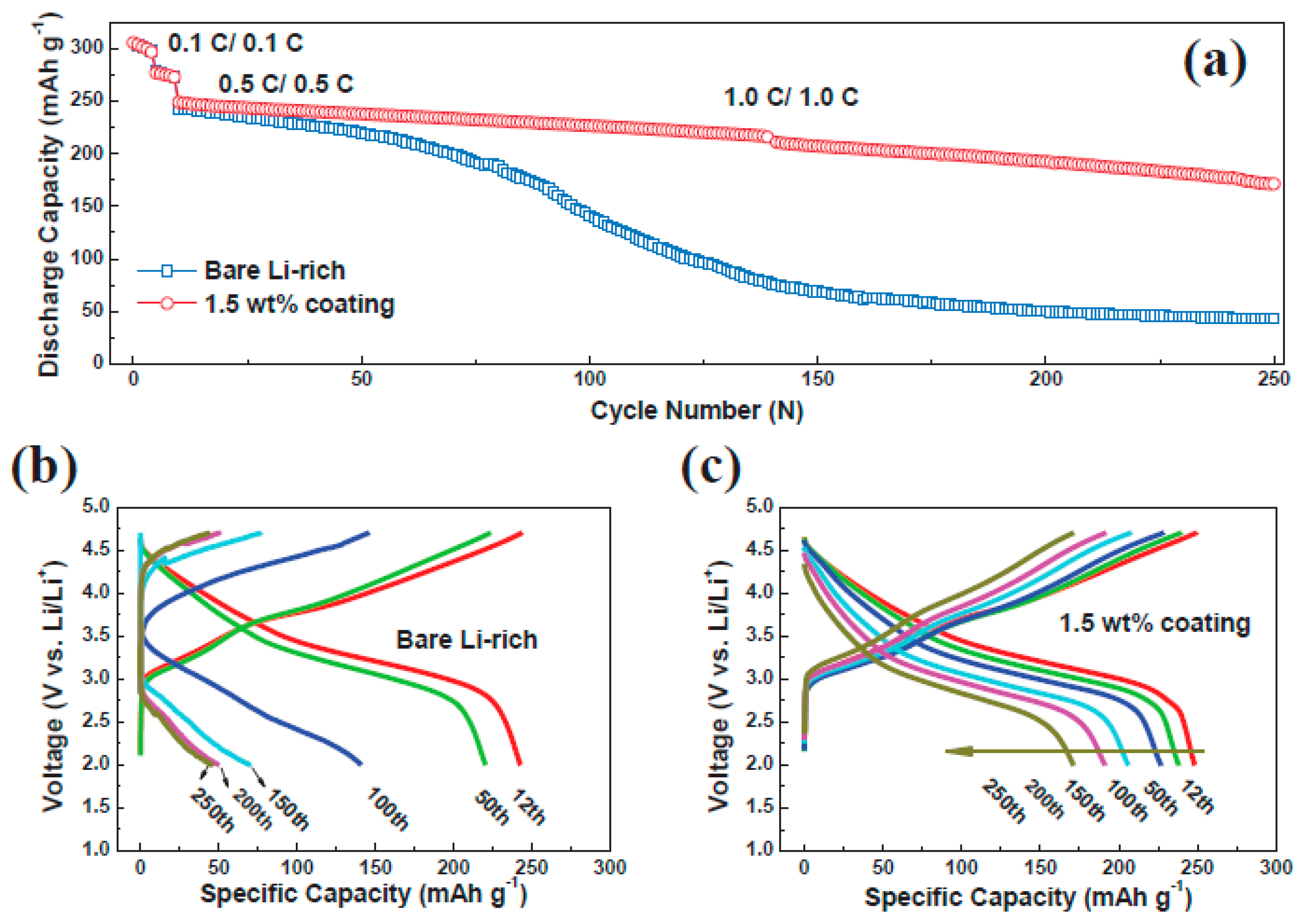
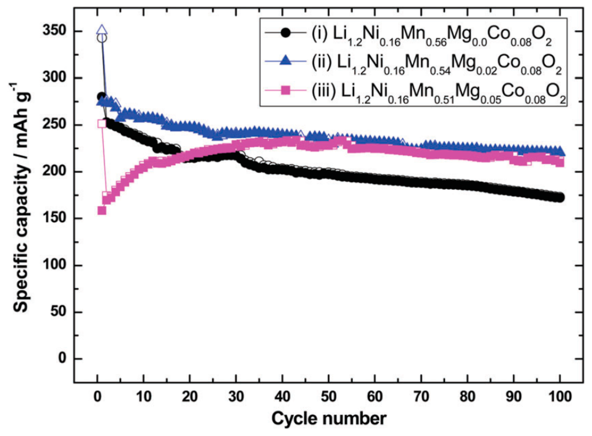
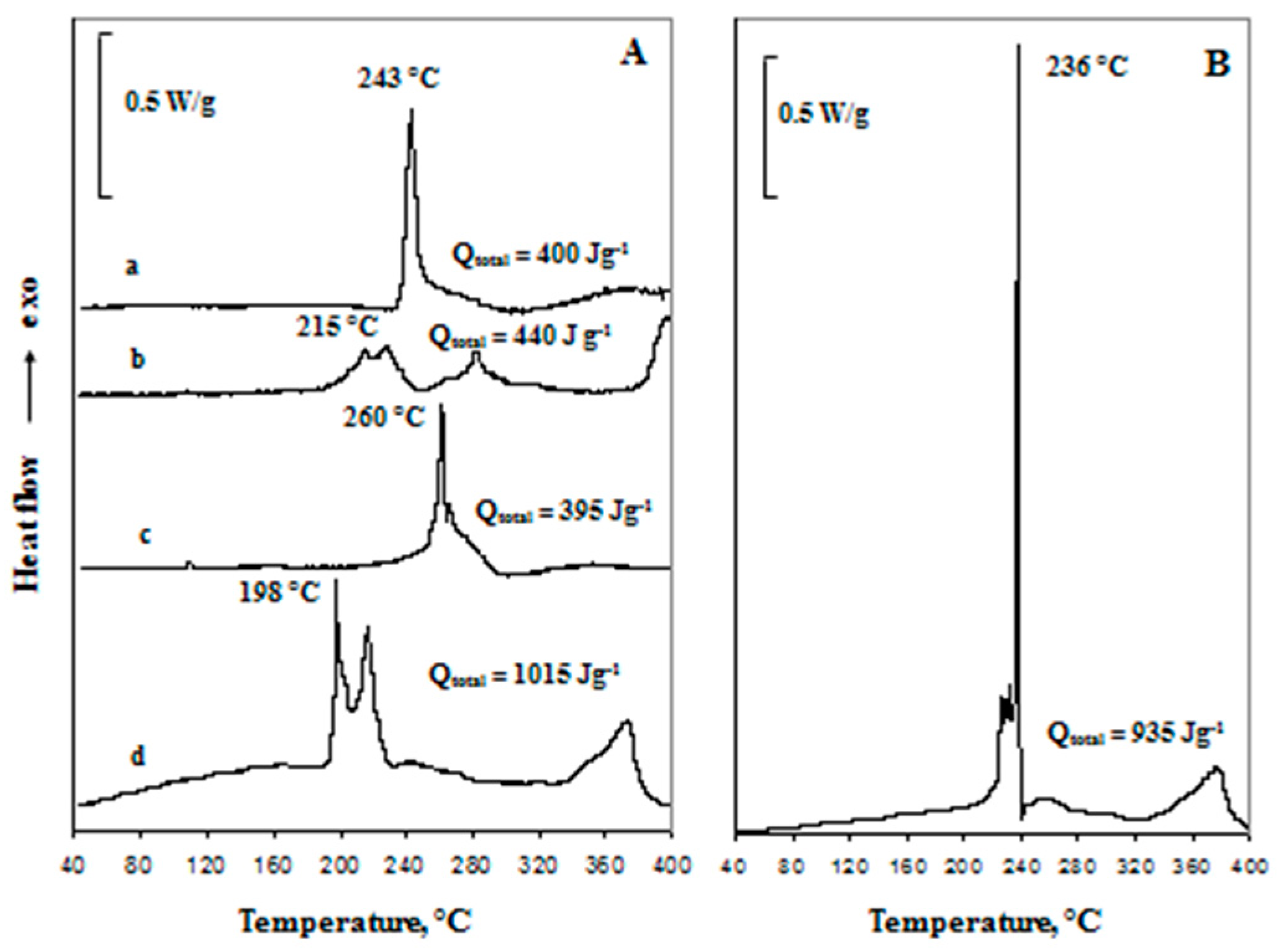
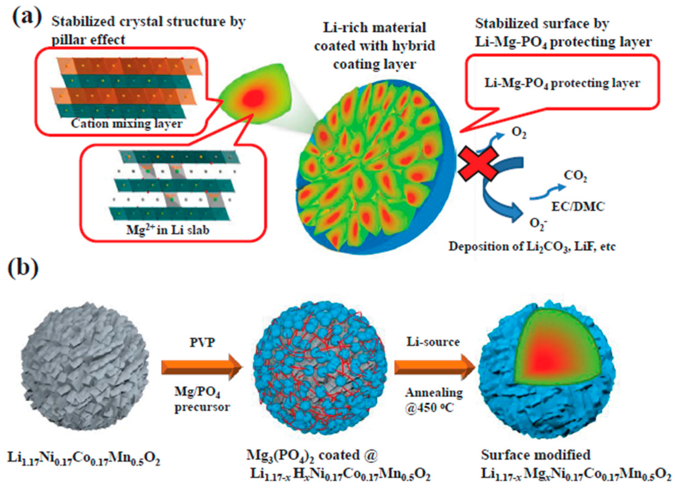
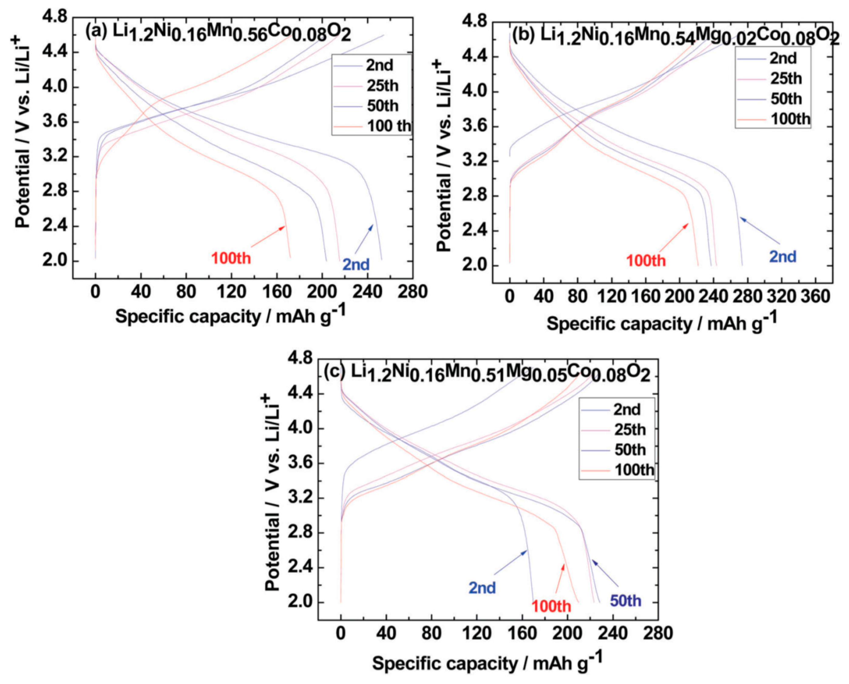
2.1. Modifications of xLi2MnO3·(1 − x)Li[NiaCobMnc]O2 Materials by Surface Coating and Lattice Doping

The general consensus in the field of Li-ion batteries is that functional surface coatings and the modification of electrodes by lattice doping may play a critical role in improving their electrochemical properties, cycle life and thermal behavior. A wide variety of materials was investigated for use as coatings, including the metal oxides SnO, Al2O3, TiO2, MgO and ZrO2 [44,45,46,47], fluorides such as AlF3 and ZrFx [48,49], and phosphates such as AlPO4 [50]. Recently, we studied the structural characteristics and electrochemical behavior of electrodes comprising Li- and Mn-rich Lix[MnNiCo]O2 cathode materials (prepared at BASF, Ludwigshafen, Germany) with the stoichiometry of xLi2MnO3·(1 − x)LiMnyNizCowO2 at 60 °C (x is in the range 0.4–0.5, and the y:z:w ratio was already reported, coated with AlF3 (about 2–3 wt %)) [16]. Special emphasis was given to the possible structural transformation during the activation and cycling of these electrodes, to solution and interfacial reactions, and to the stability of the AlF3 coating during prolonged charge/discharge cycling at 60 °C. We also studied possible interactions between the aluminum fluoride and the core of the active material, to better understand the effect of this coating on all the chemical, electrochemical and thermal processes of the electrodes. For the purpose of conducting Rietveld analysis and in keeping with previous studies, we confirm that the structure of the xLi2MnO3·(1 − x)Li[MnyNizCow]O2 pristine material is composed of two structurally compatible constituents: the monoclinic component Li2MnO3 (space group C2/m) and the rhombohedral component LiMO2 (space group R 3 ¯ m ) (M = Mn, Ni, Co). These two layered Li2MnO3 and LiMO2 nanodomains exist side by side in the structure. From the Rietveld refinement for the xLi2MnO3·(1 − x)Li[MnyNizCow]O2 pristine material coated with AlF3, the Bragg R-factors for the rhombohedral and monoclinic phases were calculated and found to be 0.046 and 0.082, respectively. The refined cell parameters for Li2MnO3 were: a = 4.945(0) Å, b = 8.594(0) Å, c = 5.023(09) Å and β = 108.86; and for Li(Ni,Co,Mn)O2: a = 2.855(4) Å and c = 14.251(1) Å.
The additional structural information about the xLi2MnO3·(1 − x)Li[MnyNizCow]O2 pristine material coated with AlF3 used here was obtained by TEM studies (Figure 2). Using the dark-field imaging technique in TEM, it was possible to infer that the AlF3 coating layer consists of extremely small (5–8 nm) AlF3 crystalline nanoparticles uniformly distributed over the particle surface. The AlF3 coating appears as thin crystalline layers covering the particle surface, indicated by arrows in the inset (c).
We have previously shown that xLi2MnO3·(1 − x)Li[MnyNizCow]O2 (x around 0.5, y:z:w around 2:2:1) electrodes can be effectively cycled at both 30 and 60 °C, with reversible capacities of about 220–250 mAh·g−1 at a rate of C/5 [16]. The AlF3-coated electrodes also exhibit stable charge/discharge behavior, providing higher capacities and lower fade upon prolonged cycling at 60 °C (Figure 3A,B). It has recently been established that the AlF3 coating (>3 wt %) may interact with the layered cathode material (Li2MnO3), leading to partial extraction (“leaching”) of the Li-ions from it and the formation of a spinel-like structure [51]. We suggest that the uniformly distributed nano-sized AlF3 possesses high surface area and may indeed act as a strong Lewis acid in reactions with the lithiated TM-oxide, resulting in partial irreversible delithiation even in the pristine (initial) state [52]. During the first charge of Li2MnO3-containing electrodes, charge compensation during the extraction of lithium occurs, involving both oxygen removal from the Li2MnO3 structure and an exchange between Li+ and H+ in the solutions, according to the formulas [53]:
2O2− (lattice) → O2 (gas) + 4e
Li2MnO3 + H+ → LiHMnO3 + Li+
Lithium carbonate is always formed in the air on TM-oxide electrodes, and its formation involves irreversible delithiation, according to:
Li2MnO3 + xCO2 → Li2−2xMnO3−x + xLi2CO3
Surface lithium carbonate can be replaced by LiF according to the reaction in the battery solution containing LiPF6 and unavoidably present free HF, according to:
Li2CO3 + 2HFsol → 2LiF + H2O + CO2
We assume that AlF3 substitutes the highly resistive LiF species and develops LiAlF4 (or Li1−xAlF3+x) at the interface, which may play an important role in the enhancement of the Li transport processes due to its exclusively high ionic conductivity, around 10−6–10−4 S·cm−1 at room temperature [54]. Along with Li1−xAlF3+x, some other species, such as an Al–F–O–H-type species, can also be formed on the active material coated with AlF3, as has been demonstrated by TEM studies. Therefore, we suggest that the higher reversible capacities of the AlF3-coated electrodes may relate to the enhanced Li+-ion transport properties at the interface that comprises the species mentioned above, since these species also promote lower impedance and more uniform and fast intercalation/deintercalation processes. For instance, at a rate of C/3, uncoated and coated materials provide ~210 and ~260 mAh·g−1, respectively. We have established that the mean charge voltage for the uncoated and AlF3-coated electrodes is almost invariant as a function of cycling, and is ~500 mV lower for the coated electrodes (Figure 3C). This can be attributed to the more energetically favorable Li+-ion extraction from the AlF3-coated electrodes and to the lower impedance of these electrodes developed upon cycling. At the same time, the mean voltage in discharge decreases continuously with cycling to ~3.1 V for both electrodes. This change in discharge voltage obviously reflects gradual structural changes in the active mass, such as the gradual development of spinel-like structural ordering, as reflected by TEM measurements. We found that during cycling at 60 °C, the impedance of the AlF3-coated electrodes is indeed smaller than that of the uncoated electrodes.
Comparing the XRD patterns of the cycled electrode (at 60 °C) with those of the pristine electrode clearly reveals the appearance of the peaks of a spinel LiMn2O4-like phase (Figure S2). It is clear, therefore, that the layered components of the integrated electrode material partially convert to a spinel-like phase upon cycling, in agreement with previously reported observations of layered-to-spinel-type structural transformation induced by electrochemical cycling [55,56,57]. The Raman spectra of the cycled xLi2MnO3·(1 − x)Li[MnyNizCow]O2 electrodes are characterized by broader main peaks and a lower ratio of intensities, attributable to some structural disordering and increased conductivity, respectively, compared to the pristine electrodes. These spectra reveal the formation of spinel-type ordering, reflected by the blue-shift of the A1g mode at ~600 cm−1 in the pristine electrodes to ~625 cm−1 in cycled material, implying partial transformation of the layered structure.
Figure 4 (charts A and B) demonstrates the differential scanning calorimetry (DSC) responses of the xLi2MnO3·(1 − x)Li[MnyNizCow]O2 (uncoated and AlF3-coated) materials in contact with the EC-DMC/1M LiPF6 solution at 40–400 °C. It was found that the thermal decomposition of the solution alone exhibits an exothermic peak at 243 °C. The calculated heat of this reaction is about 400 J/g. The DSC response of xLi2MnO3·(1 − x)Li[MnyNizCow]O2 with the EC-DMC/1M LiPF6 solution does not demonstrate the thermal decomposition peak of the electrolyte solution. However, at least three exothermic peaks appear, starting at 215 °C, and they are accompanied by a total heat evolution of 440 J·g−1. The observed exothermic peaks are related to the well-known pronounced thermal reactions between lithiated transition-metal-oxide cathode material and solution species (curve b). Surface modification of xLi2MnO3·(1 − x)Li[MnyNizCow]O2 with aluminum fluoride significantly enhances the thermal stability, shifting the onset of the thermal reactions to higher temperatures and lowering the total specific heat of the reactions by more than 10% (curve c). We suggest that the AlF3 coating significantly reduces the direct contact area between the active mass and the solution species. Since the electrochemical or chemical delithiation of the monoclinic component Li2MnO3 of the cathode material is accompanied by oxygen evolution, this oxygen can react with AlF3 to form Al2O3 at 200 °C [58]. Supposedly, alumina thus formed does not sufficiently protect the surface of the material at elevated temperatures, and the interfacial reactions may accelerate to more than 200 °C. Indeed, the DSC measurements detect an onset of very slow exothermic reactions at 220 °C, which is about 20 °C higher than the temperature of the uncoated material. The strong exothermic peak appears at 260 °C, 45 °C above the temperature of the uncoated material. The DSC response obtained from the uncoated xLi2MnO3·(1 − x)Li[MnyNizCow]O2 active mass after the 20th charge (delithiated state at 60 °C) shows three well-resolved exothermic peaks (curve d). The exothermic peak observed with the cycled electrode is 198 °C, accompanied by a specific heat release of ~1015 J·g−1, while the DSC response of the charged AlF3-coated cathode material (delithiated state at 60 °C) after 20 cycles (Figure 4 chart B) differs significantly from that of the pristine state. The thermal stability decreases and the temperature of the main exothermic reaction is shifted to ~236 °C. The ratio between the exothermic peaks changes and the heat release increases more than twofold. Such differences may be related to the surface and bulk changes of the cathode material upon cycling, and the results obtained correlate well with previous reports [58,59,60,61]. To summarize, the surface modification by AlF3 coating of these Li- and Mn-rich cathode materials improves their thermal stability in pristine and delithiated states compared to the uncoated electrodes. These results are in line with the TEM data, demonstrating that even after cycling at 60 °C, the AlF3 coating still remains stable on the surface of the cathode material.
Novel hybrid materials composed of Mg2+ and LiMgPO4 have been proposed by Liu et al [62]. as protective surface layers on Li- and Mn-rich Li1.17Ni0.17Co0.17Mn0.5O2 material in order to lessen the capacity fading and voltage decay during prolonged cycling at 24 and 60 °C. Figure 5 shows a schematic illustration of surface-coated cathode material with hybrid LiMgPO4 material and preparation of the surface-modified Li1.17N0.17C0.17Mn0.5O2. From the Rietveld refinement of the XRD patterns, it was suggested that the LiMgPO4 surface-coated layered material was surface-doped, resulting in [Li1.17−yMgy][Ni0.17Co0.17Mn0.5]O2. In the Li2MnO3 phase, the Mg2+ ions prefer to occupy the Li+ (4h) sites. This suppresses TM migration from the TM layer to the lithium layer, thereby reducing the structural transformation from the layered (space group R 3 ¯ m ) to the spinel-like phase. It was also hypothesized that during the coating process, the Li2MnO3 phase is activated with simultaneous hybrid surface coating, which leads to Li-rich material with better rate capability and initial Coulombic efficiency at 24 °C, compared to the bare material.
Although upon long cycling at room temperature the capacity retention is almost the same for the bare and 1.5 wt % surface-coated sample, cycling at an elevated temperature of 60 °C is significantly better for the 1.5 wt % LiMgPO4-coated samples. The authors show (Figure 6) that the surface-coated sample with 1.5 wt % LiMgPO4 delivers an initial discharge capacity of 264 mAh·g−1 at a rate of 0.5 C with a capacity retention of 87.1%, whereas the bare sample shows only 33.4% capacity retention after 75 cycles. The LiMgPO4-coated Li-rich layered material serves as a protective layer that minimizes electrolyte contact with the active material particles, thereby reducing the attack from acidic HF and eliminating metal dissolution at a high operating temperature. Consequently, in the LiMgPO4-coated Li- and Mn-rich layered material mentioned above, the voltage fade due to cation migration and structural transformation is reduced, thereby enhancing the cycling stability of the cathode material at elevated temperatures.
The atomic layer deposition (ALD) technique has been used to obtain uniform surface coatings with controlled thickness on top of the Li- and Mn-rich cathode materials [63]. Choi et al. coated the acid-treated 0.3Li2MnO3·0.7LiMn0.60Ni0.25Co0.15O2 composite electrode material with a thin Al2O3 layer [64]. By the ALD technique, they demonstrated that the alumina-coated electrodes improve not only the discharge capacity but also the cycling stability, compared to the uncoated material. After 10 ALD cycles, the 0.1-M-HNO3-treated electrode material coated with Al2O3 shows better capacity retention. Here, Al2O3 forms a stable protective layer that can quickly transport Li+ ions across the interface of the cathode particles during charging and discharging.
In a surface-modification technique proposed by Oh et al., the Li- and Mn-rich layered-cathode 0.4Li2MnO3·0.6LiNi1/3Co1/3Mn1/3O2 material was surface-coated with several layers of reduced graphene oxide (rGO) by the spray-dry technique and treated with hydrazine (HGO) solution to obtain a better electronic conducting pathway onto the bare cathode surface [65]. A schematic view of the HGO-coated material is shown in Figure S3. The Li2MnO3 phase on the surface is stabilized by activating its structure with HGO treatment. This surface treatment of layered cathode materials by HGO greatly increases the initial Coulombic efficiency and mitigates voltage fading upon extended cycling (Figure S4). In this figure, the specific capacities obtained at low rates are almost the same for the pristine and HGO samples, but the rate capabilities are clearly distinguishable at higher rates, mainly due the conducting HGO layer at the surface. Upon long cycling, the surface-treated samples mentioned above demonstrate a stable discharge capacity over 100 cycles, with a capacity retention of 78%, whereas the specific capacity of the uncoated sample falls abruptly after 30 cycles. This improvement in the HGO-coated Li-rich electrodes emerges by suppressing the phase transition of the bulk material from the layered phase to spinel-like phases and rock-salt phases, which is the main reason behind the capacity fading observed in all Li-rich layered cathode materials.
The influence of cation dopants (such as Mg2+) in xLi2MnO3·(1 − x)Li[MnyNizCow]O2 materials was studied by partial replacement of Mn in a typical material (the general formula Li1.2Ni0.16Mn0.56−xMgxCo0.08O2). Two dopant levels were used, x = 0.02 and x = 0.05. The material was synthesized by the self-combustion reaction (SCR) from the precursors of LiNO3, Ni(NO3)2, Mn(NO3)2, Co(NO3)2 and Mg(NO3)2, as reported earlier [66]. These precursors and sucrose act as oxidants and fuel, respectively, in the SCR. The XRD patterns of both samples can be indexed as a hexagonal O3 α-NaFeO2 structure (space group R 3 ¯ m ), with a few broad peaks that appear in the 2θ range of 20°–25° (Figure S5). These diffraction peaks result from the super-lattice ordering of Li and Mn in the transition-metal layers associated with the presence of the monoclinic phase Li2MnO3. No additional XRD peaks were detected upon Mg doping, indicating the absence of any impurity phase and the proper substitution of Mg for Mn. The Mg doping resulted in a slight increase in the lattice parameters and the unit cell volume of the doped material (V = 201 Å3) compared to the undoped one (V = 200.8 Å3). This is probably because of the large size of Mg2+ (0.76 Å) compared to Mn4+ (0.53 Å). Galvanostatic charge/discharge cycling of the Mg-doped Li- and Mn-rich cathodes was performed vs. Li counter-electrodes in coin-type cells at 25 mA·g−1 (about C/10 rate). The voltage range was 2.0–4.7 V in the first cycle and 2.0–4.6 V in the 100 subsequent cycles. The voltage profiles measured from these electrodes demonstrated a plateau around 4.5 V corresponding to the activation of Li2MnO3. However, the first charge voltage plateau region is shortened when the dopant level of Mg is x = 0.05. A high specific capacity of about 340 mAh·g−1 was initially obtained for the undoped Li1.2Ni0.16Mn0.56Co0.08O2 cathodes, while charging capacities of about 348 and 250 mAh·g−1 were measured in the first cycle for the electrodes doped with Mg at values of x = 0.02 and x = 0.05, respectively. This result demonstrates that Mg doping only slows the initial activation process of the monoclinic Li2MnO3 component with the higher amount of dopant (x = 0.05). This is in agreement with the result reported in the literature for the partial substitution of Mn by Sn [67]. The partial substitution of Mn by Mg suppresses the capacity resulting from the activation of Li2MnO3. This is because the formation of stronger Mg–O bonds compared to Li–O bonds suppresses the irreversible extraction of Li+ and O2 during the charge in the first cycle [68]. The charge/discharge voltage profiles relating to several cycles during the prolonged cycling of Li1.2Ni0.16Mn0.54Mg0.02Co0.08O2 and Li1.2Ni0.16Mn0.51Mg0.05Co0.08O2 are presented in Figure 7. The wide plateau at potentials higher than 4.5 V in the first cycle, corresponding to the activation of Li2MnO3, disappear during the charge in subsequent cycles. In the second cycle, the discharge capacities are found to be about 270 and 170 mAh·g−1 for Li1.2Ni0.16Mn0.54Mg0.02Co0.08O2 and Li1.2Ni0.16Mn0.51Mg0.05Co0.08O2, with a Coulombic efficiency approaching 99%. As established earlier, there is a decrease in the specific capacity and discharge voltage decay of the undoped electrode materials upon cycling. In our experiments, the Mg-doped (x = 0.02) samples demonstrate this effect [69]. However, when the Mg-doping level is 0.05 for Li1.2Ni0.16Mn0.51Mg0.05Co0.08O2, the specific capacity increases during the initial 20–30 cycles and stabilizes at about 230 mAh·g−1.
The specific capacity obtained from galvanostatic cycling at a rate of C/10 as a function of the cycle number is shown in Figure 8. In the case of the Li1.2Ni0.16Mn0.56Co0.08O2 electrodes, a discharge capacity of 250 mAh·g−1 is obtained in the second cycle, which decreases to 175 mAh·g−1, thus retaining about 70% capacity after 100 cycles (Figure 8i). For the Li1.2Ni0.16Mn0.54Mg0.02Co0.08O2 cathodes, the specific capacity drops from 270 mAh·g−1 (second discharge) to 220 mAh·g−1, thus retaining about 81.5% capacity after 100 cycles (Figure 8ii). The specific capacity of the Li1.2Ni0.16Mn0.51Mg0.05Co0.08O2 electrodes increases from 170 mAh·g−1 (second discharge) to 230 mAh·g−1 after about 20 cycles, finally decreasing to 210 mAh·g−1, with a capacity retention of about 91.3% (Figure 8iii). Such an increase in capacity during the first few cycles indicates, again, the gradual activation of Li1.2Ni0.16Mn0.51Mg0.05Co0.08O2 upon cycling, which is in line with previous reports [68]. Hence, the minor substitution of Mn by Mg results in an improvement in the cycling stability during prolonged cycling of these Li- and Mn-rich cathodes.

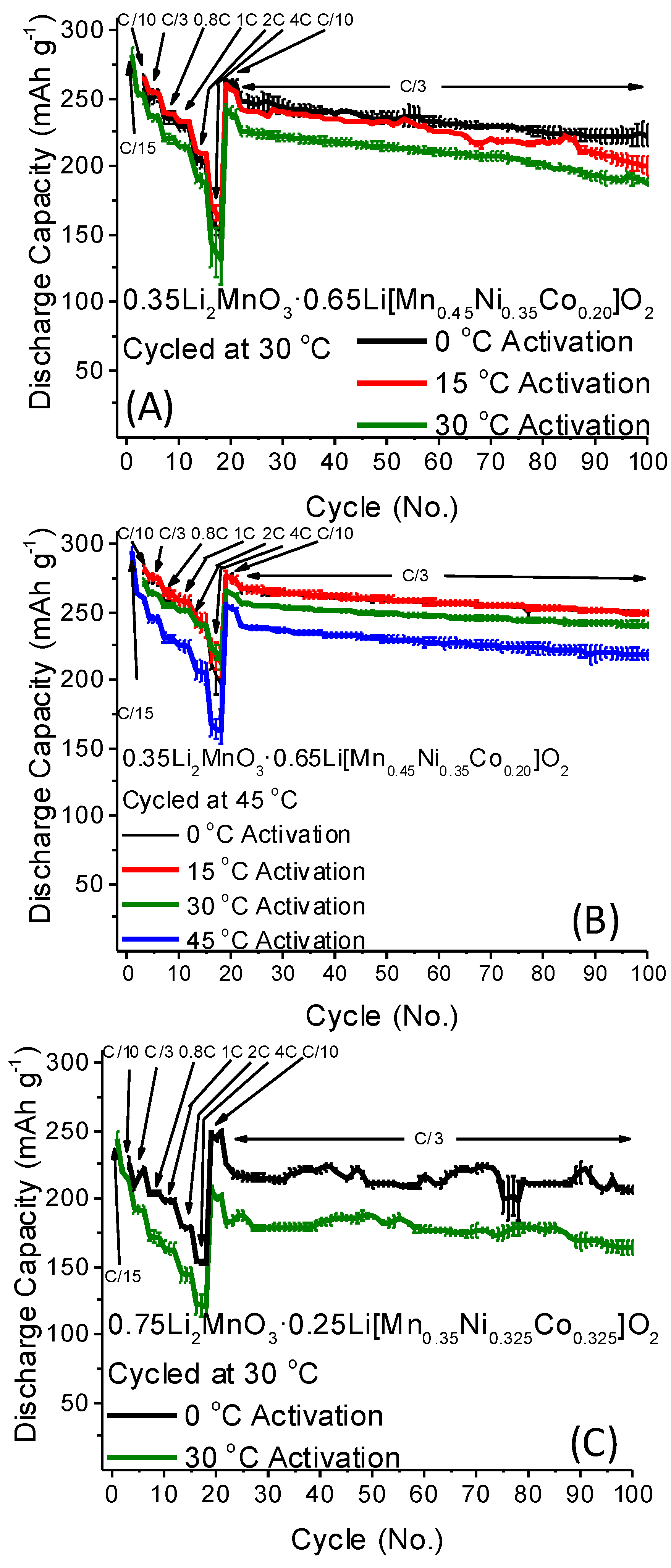
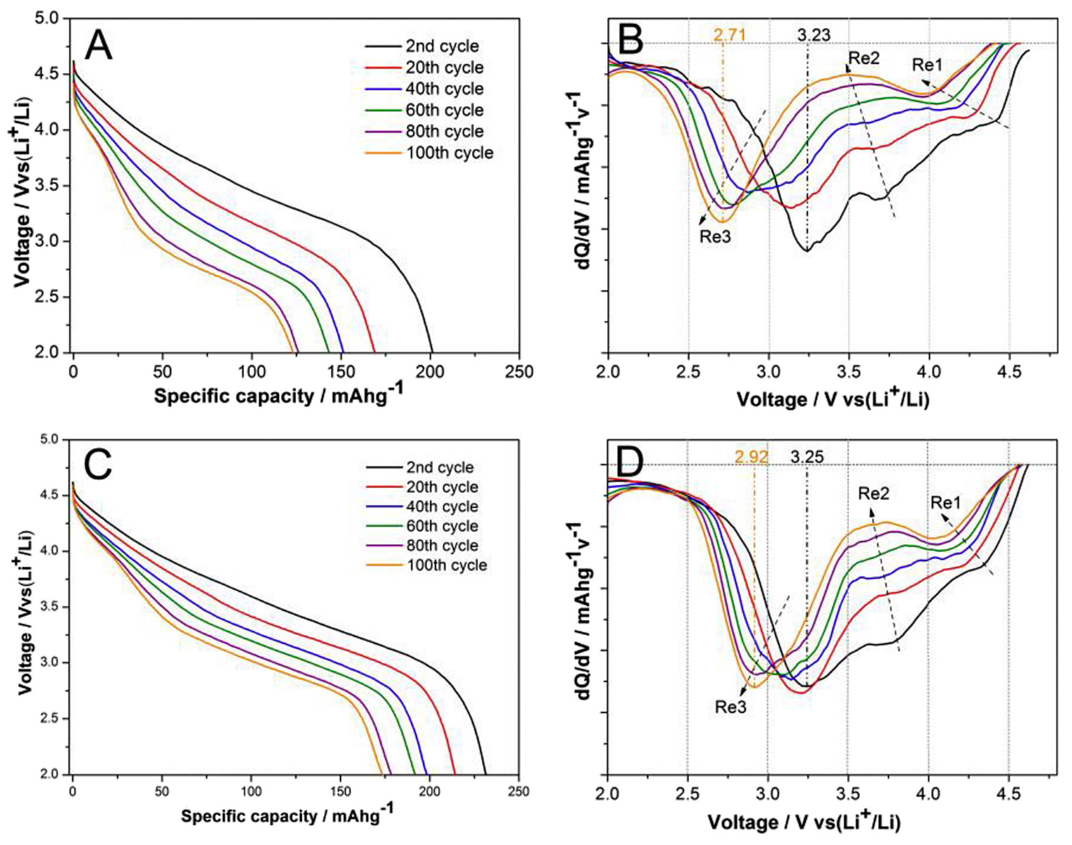
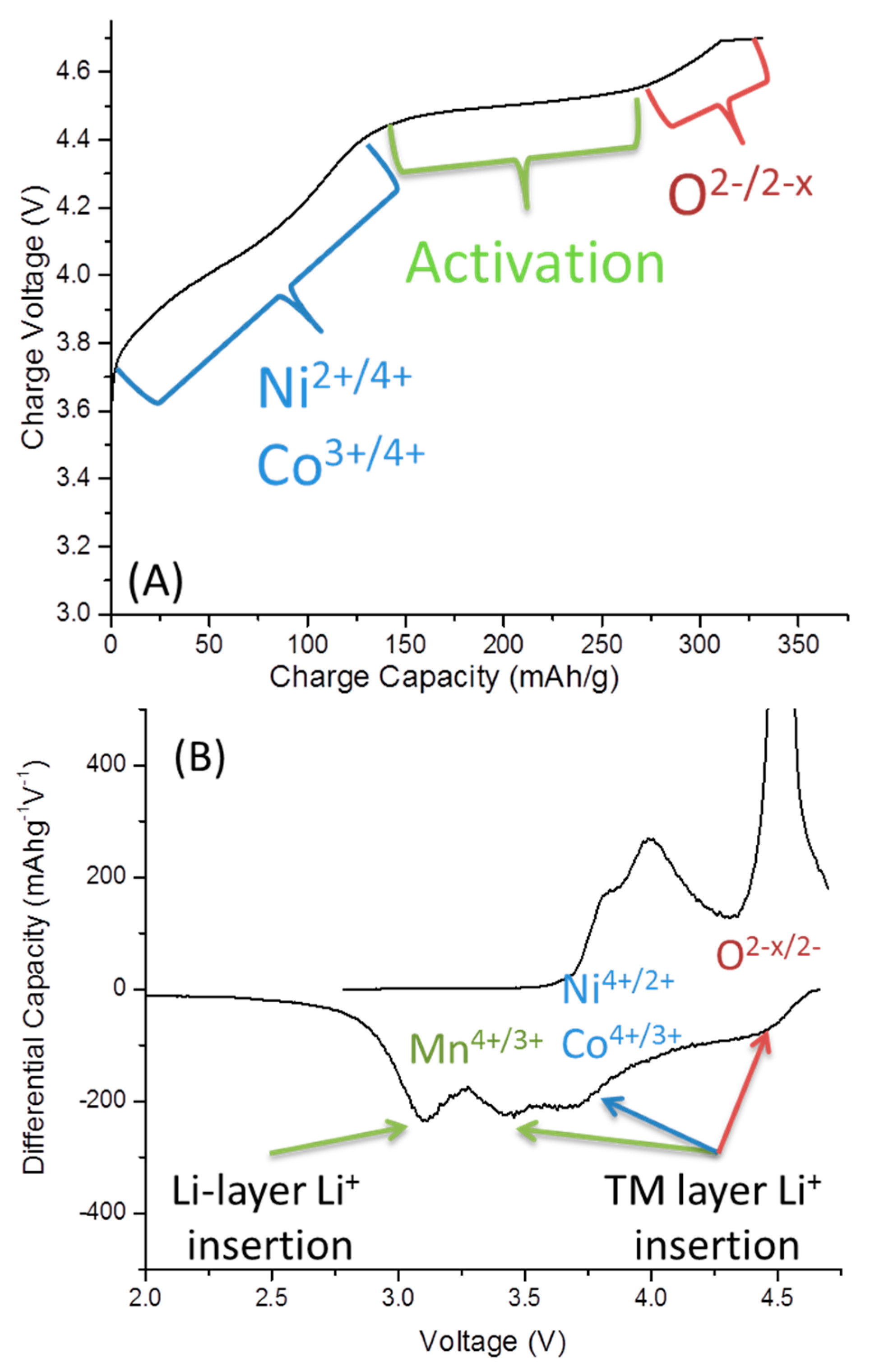
2.2. Low-Temperature Activation of xLi2MnO3·(1 − x)Li[MnyNizCow]O2 Materials

Recently, our group has discovered a unique phenomenon: the activation of Li- and Mn-rich materials at lower than ambient temperatures (e.g., 0 or 15 °C) results in a ~10% enhancement in the subsequent discharge capacity of these materials [41,71]. This effect has been shown in multiple formulations of xLi2MnO3·(1 − x)Li[MnyNizCow]O2. The results for two different materials are depicted in Figure 9 [41,71]. The mechanism behind the enhanced discharge capacity from low-temperature activation is still under investigation. Since the first cycle of the Li- and Mn-rich materials must be extended to higher potentials, at which electrolyte oxidation is enhanced, the surface films may play a role, showing lower resistance for cells activated at lower temperatures [41,71].

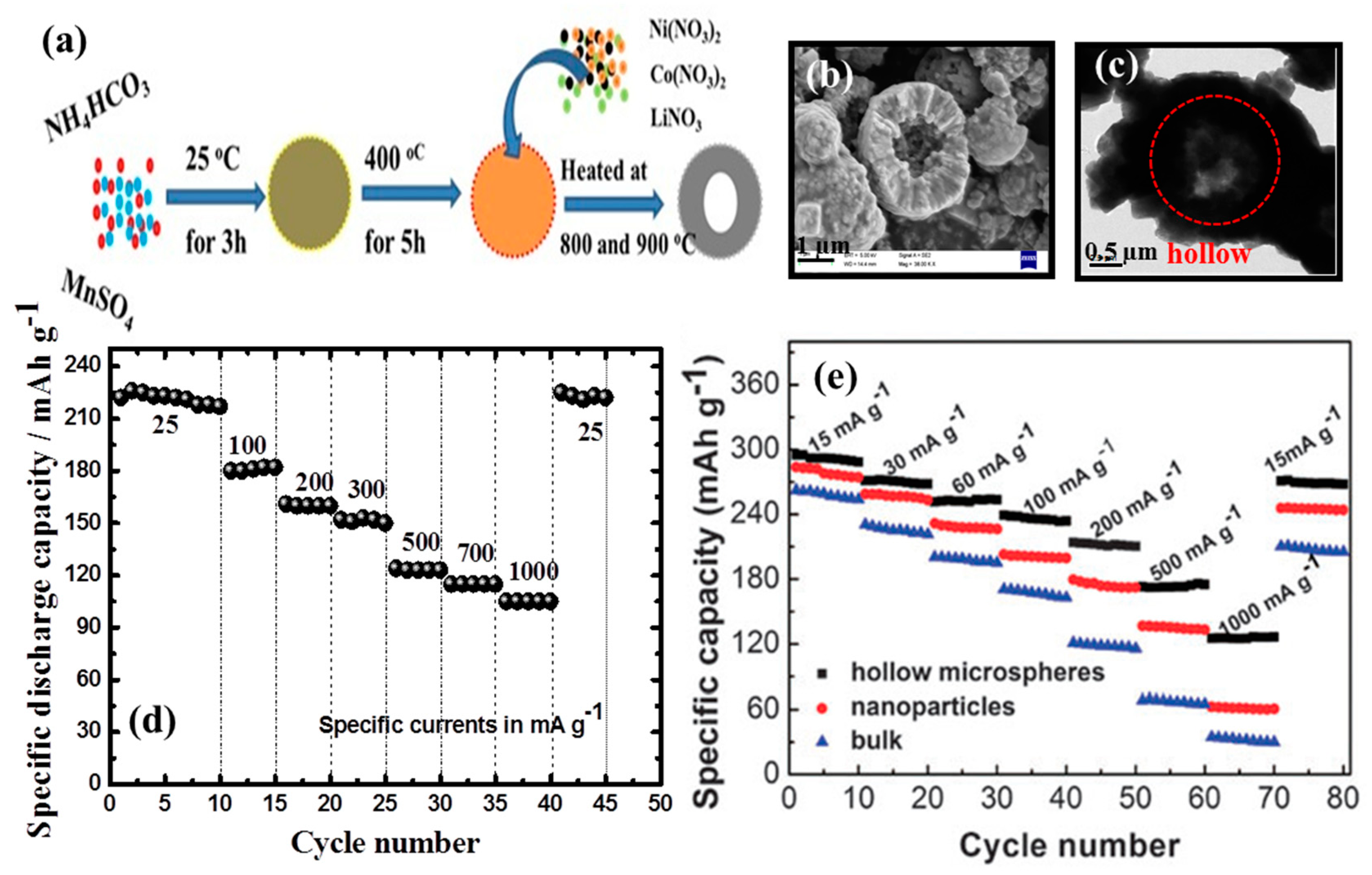
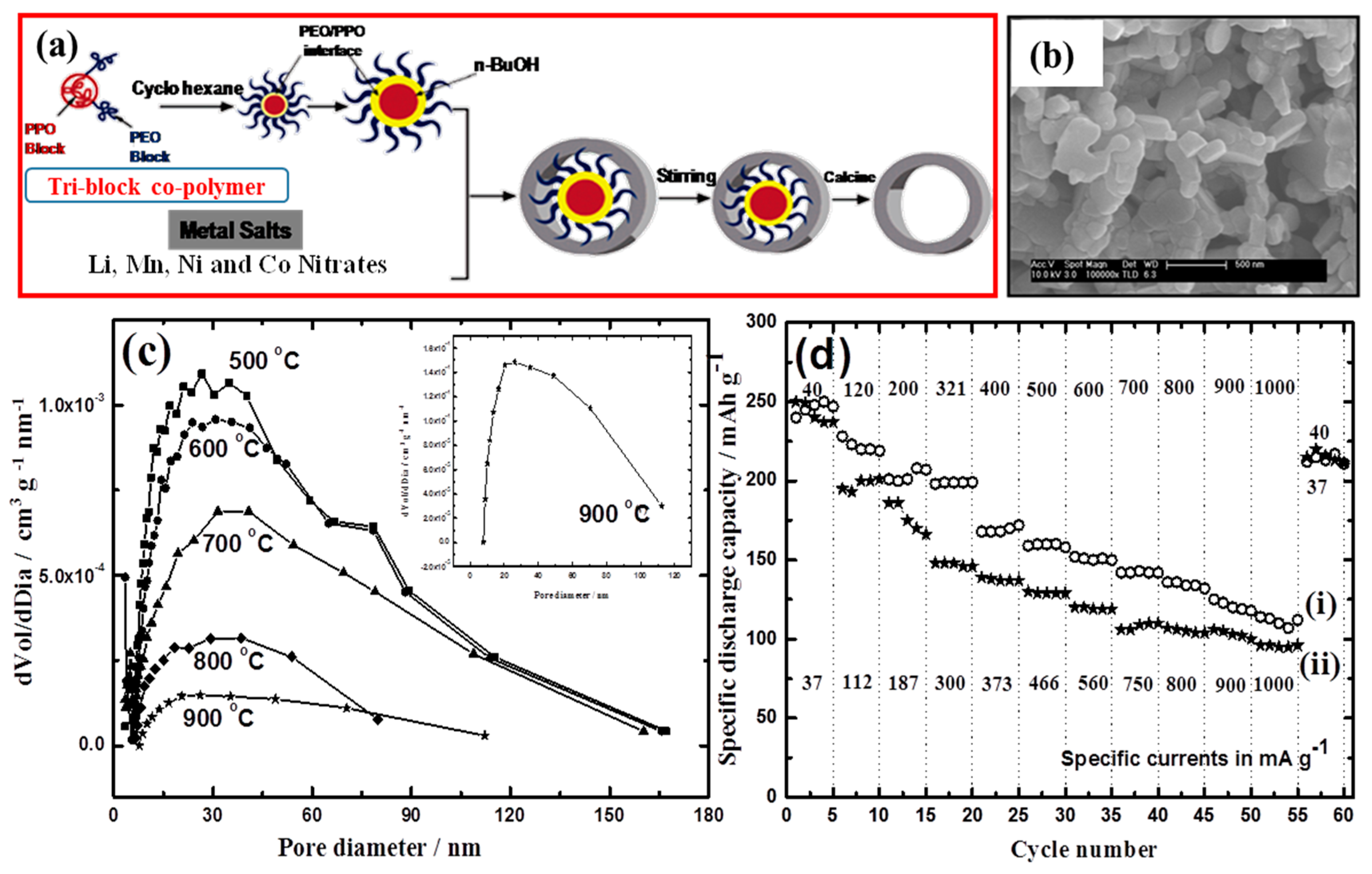
2.3. Porous Li- and Mn-Rich High-Energy-Density Cathode Materials

As discussed above, Li- and Mn-rich cathodes present thermodynamic and kinetic challenges, such as low Coulombic efficiency, poor rate capability and fast capacity fading. To overcome these issues, metal-ion doping of the lattice and surface modifications by coating are being adopted. Another approach is to focus on the fabrication of nanostructured cathode materials with well-defined morphologies, such as porous structures and hollow spheres. The selection of nano-sized materials potentially improves the mass transport of the cathode by increasing its surface area, shorting the diffusion lengths and providing higher intercalation/deintercalation rates. Apart from the advantages of the high specific surface area of the nanoparticles, the nano-sized materials show certain disadvantages: the lowering of thermodynamic stability, higher contact resistance, low packing density and high side reactions at the electrode/electrolyte solution interface. Therefore, these materials cannot be used in practical applications. Compared to nanomaterials, micrometer-sized particles have relatively high thermodynamic stability, low contact resistance and low specific surface area, and they exhibit less side reactions. In contrast, the advantage in porous structured materials is their good electrode/electrolyte solution interface through the pores and promising structural stability via low contact resistance through the walls of the pores. Therefore, electrodes prepared from porous materials are expected to possess high rate capability, since the electrolyte can seep into the particles and enhance the contact area of the electroactive surface with the electrolyte. This shortens the diffusion length of Li+-ion transport and enhances the kinetics [72,73]. As a result, these materials can withstand high currents during charge/discharge cycling. Furthermore, the electrode material can tolerate the volume expansion and contraction that may occur during Li intercalation/deintercalation processes.
Porous materials can be classified as microporous (<2 nm), mesoporous (2–50 nm), and macroporous (>50 nm), based on the pore size. They are prepared by various synthetic routes, such as template and non-template methods. Non-template methods are hydrothermal, sonication and microwave routes. Template methods use a substrate on which the material nucleates, grows and then the product can be separated from the substrate. There are several kinds of templates: soft templates (polymers), hard templates (SiO2, polymer beads) and self-templates (one of the precursors, which acts as a template). In Table S1, which presents an overview of the literature data on porous cathode materials for Li-ion batteries (LIBs), we demonstrate the relation between the synthetic method of porous materials and their electrochemical performance. In addition, several approaches are discussed below with detailed benefits of using porous materials.
Li- and Mn-rich Li1.2Mn0.54Ni0.13Co0.13O2 material with hierarchical porous micro-sized rods was prepared by the facile hydrothermal method, with discharge capacities of about 281, 255, 232, 226, 202 and 173 mAh·g−1, at rates of 0.1 C, 0.2 C, 0.5 C, 1 C, 2 C and 5 C, respectively, measured as shown in Figure S6A [74]. Ma et al. [75] reported hierarchical Li1.165Mn0.501Ni0.167Co0.167O2, which was prepared by the ultrasonic-assisted co-precipitation method with two steps of heat treatment by adopting graphene and carbon nanotubes as the functional framework. These materials exhibit the specific capacity of 277 mAh·g−1 at a rate of 0.1 C and 61 mAh·g−1 at a rate of 10 C (Figure S6B). Munichandraiah et al. prepared porous Li- and Mn-rich cathodes (Li1.2Mn0.53Ni0.13Co0.13O2, Li1.2Mn0.54Ni0.22Fe0.04O2, Li1.2Mn0.53Ni0.13Fe0.132, Li1.2Mn0.6Ni0.2O2) by the reverse micro-emulsion method using a tri-block co-polymer as a soft template [76,77,78,79]. Soft-template synthesis by the inverse micro-emulsion route is useful for the preparation of small particles. When a small volume of an aqueous phase consisting of the reactants is dispersed in a large volume of a non-aqueous phase, the reactants are confined to micrometer-sized aqueous reaction zones and the size of the product particles is limited to the size of the aqueous droplets, which are stabilized by surfactant molecules. Sub-micrometer/nanometer-sized particles were synthesized by this route [80]. The typical reverse micro-emulsion route contains hydrocarbon (aliphatic or aromatic) as an oil phase, co-surfactant (4 to 8 carbon-chain aliphatic alcohol) and a small amount of aqueous phase. As shown in the schematic diagram in Figure 10a, the presence of tri-block polymeric templates such as P123, F068 and F127 is expected to facilitate porosity on the product particles. These templates follow the general formula –[(EO)n–(PO)m–(EO)n]–, (n = 20, m = 70 for P123, n = 78, m = 30 for F068, n = 106, m = 70 for F127), where EO and PO are ethylene oxide and propylene oxide, respectively.
The combination of a hydrophobic and hydrophilic PO block leads to the creation of porosity [81]. Sub-micrometer-sized porous cathode materials can be synthesized by combining the salient features of inverse micro-emulsion and the polymeric template. The precursor of the porous Li1.2Mn0.53Ni0.13Co0.13O2 is heated to several temperatures between 500 and 900 °C. The product samples possess mesoporosity with broadly distributed pores, with about 30-nm diameters (Figure 10C). Note that there is a decrease in the pore volume as well as in the surface area with the increase in the temperature of preparation. The discharge capacity of the Li1.2Mn0.53Ni0.13Co0.13O2 samples prepared at 800 and 900 °C is ~250 mAh·g−1 at a specific current of 40 mA·g−1, showing good cycling stability and rate capability (Figure 10D).
A hierarchically porous layered lithium-rich oxide, 0.5Li2MnO3·0.5LiMn1/3Ni1/3Co1/3O2, was synthesized by the co-precipitation of metal oxalates, with the assistance of a moderate polyethylene glycol (PEG2000) [82]. It was found that the as-synthesized oxide exhibits excellent rate capability and cyclic stability as an electrode in Li-cells, delivering an initial discharge capacity of 262 mAh·g−1 at 0.1 C and 135 mAh·g−1 at 4 C, and possessing a capacity retention of 83% after 200 cycles at 4 C. The discharge profiles and corresponding dQ/dV plots are shown in Figure 11. Both samples display a similar trend in voltage fading, as can be seen by the decreasing potential profiles with increasing cycle numbers (Figure 11A,C), but without PEG-0.5Li2MnO3·0.5LiMn1/3Ni1/3Co1/3 O2 electrodes exhibit a more serious decline in discharge capacity than electrodes comprising PEG2000-0.5Li2MnO3·0.5LiMn1/3Ni1/3Co1/3O2 composite material. This result shows that PEG2000-0.5Li2MnO3·0.5LiMn1/3Ni1/3Co1/3O2 has better structural stability than 0.5Li2MnO3·0.5LiMn1/3Ni1/3Co1/3O2. This difference between the two materials can be more easily observed from the dQ/dV plots in Figure 11B,D. Three main reduction processes (which accompany Li-intercalation) can be identified: Re1 at about 4.5 V is related to Li occupation in the tetrahedral sites; Re2 at 3.7 V can be ascribed to Li occupation in the octahedral sites corresponding to Ni4+/Ni2+ and Co4+/Co3+; and Re3 at <3.5 V can be explained by Li occupation in the octahedral sites associated with Mn4+/Mn3+ redox [83,84]. Further delithiation beyond 4.5 V during the first cycle leads to oxygen vacancies and the subsequent migration of transition metal ions into lithium sites and lithium ions into tetrahedral sites, resulting in a distorted oxygen lattice [85,86,87,88]. Figure 11B,D shows that all the reduction peaks shift with cycling, but the shifting is more serious for 0.5Li2MnO3·0.5LiMn1/3Ni1/3Co1/3O2 than for PEG2000-0.5Li2MnO3·0.5LiMn1/3Ni1/3Co1/3O2. This observation reveals that PEG2000-0.5Li2MnO3·0.5LiMn1/3Ni1/3Co1/3O2 is more structurally stable than 0.5Li2MnO3·0.5LiMn1/3Ni1/3Co1/3O2 under deep cycling.
The porous Li1.2Ni0.13Co0.13Mn0.54O2 nanoplate was prepared by a colloidal crystal template assembled by poly(methyl methacrylate) (PMMA) beads [89]. In Figure S7, the cycling performance of the porous Li1.2Ni0.13Co0.13Mn0.54O2 and bulk Li1.2Ni0.13Co0.13Mn0.54O2 materials are compared at different discharge rates over the voltage range of 2.0–4.8 V. During the rate capability studies, all the charging steps were carried out at 0.1 C and the discharge was performed over the range of 0.1–1 C rates. Clearly, the porous Li1.2Ni0.13Co0.13Mn0.54O2 shows higher discharge capacity than the bulk Li1.2Ni0.13Co0.13Mn0.54O2 at all C-rates. These results indicate that porous Li1.2Ni0.13Co0.13Mn0.54O2 cathode material shows high specific capacity and improved cycling stability compared to the bulk Li1.2Ni0.13Co0.13Mn0.54O2 prepared by the traditional method. Nanoparticles of the layered Li- and Mn-rich cathode Li[Li0.2Ni0.2Mn0.6]O2 were synthesized via two-step hydrothermal reactions combined with a calcination process, where carbon spheres were used as templates. This cathode material delivers optimal cycling ability, minimal voltage decay and maximal discharge capacities of 239, 219, 205 and 183 mAh·g−1 at rates of 1, 2, 5 and 10 C, respectively [90].
In the past, the hollow nanostructured electrode materials were generally prepared by template methods, and the removal of the templates was difficult [72]. In contrast, self-template or sacrificial-template methods are convenient for the preparation of hollow materials. The self-template not only acts as a reactant precursor, but also allows the formation of hollow particles [91,92]. Hollow 0.3Li2MnO3·0.7LiNi0.5Mn0.5O2 microspheres were synthesized on a large scale through a simple in situ template-sacrificial route. Starting from porous MnO2 microspheres, hollow microspheres assembled with 0.3Li2MnO3·0.7LiNi0.5Mn0.5O2 nanocrystals were produced (Figure 12) [93]. This material exhibits a highly reversible capacity of about 295 mAh·g−1 over 100 cycles and excellent rate capability (125 mAh·g−1 at 1000 mA·g−1) as a cathode in Li-cells. An important advantage is that dual and multi-porous Li- and Mn-rich materials with an advantageous distribution of pores between 2–5 nm and 30–50 nm. While small pores act as transport channels for ions to the bulk of the electrode, larger pores allow for easy mass transport of solvated ions [94,95].

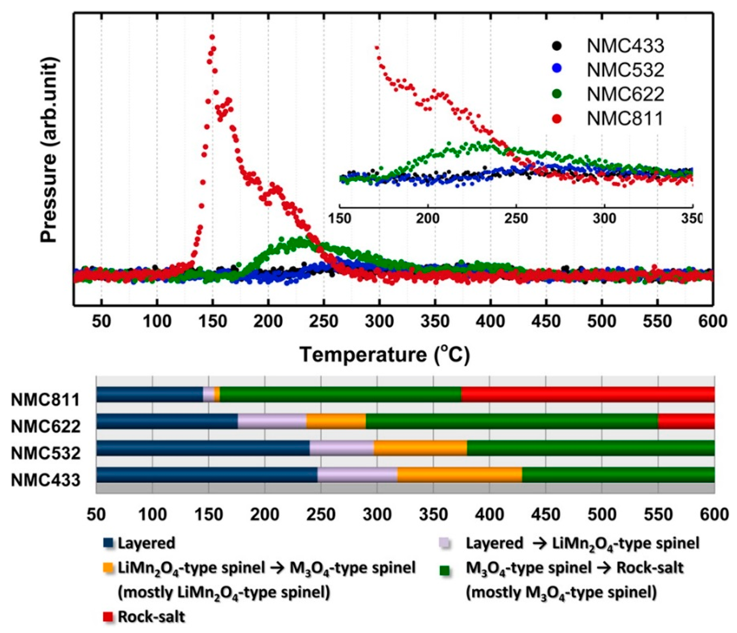
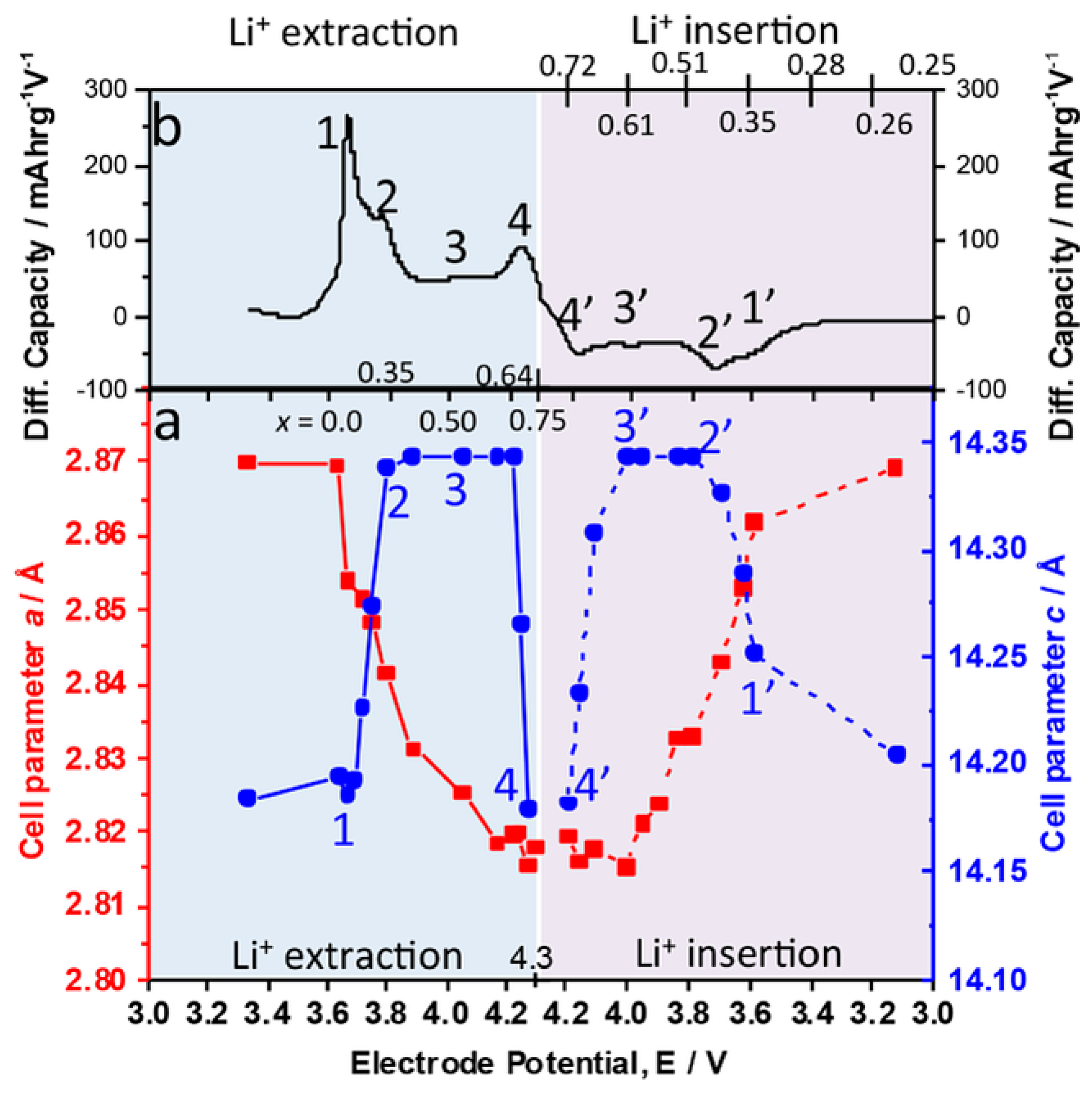
3. Nickel-Rich Li[NixCoyMnz]O2 Layered Structure Materials (NCM, x > 0.5, x + y + z = 1)

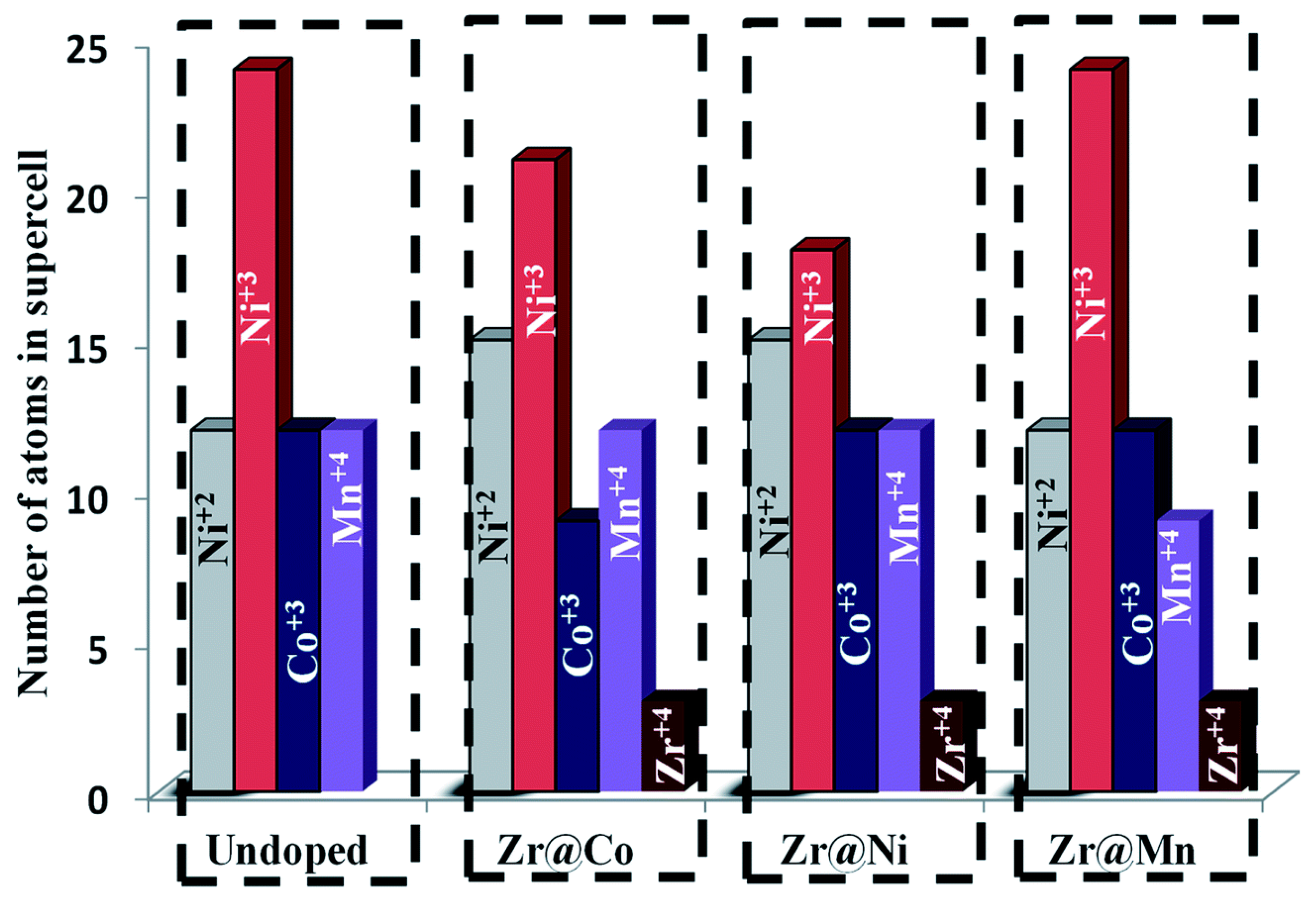
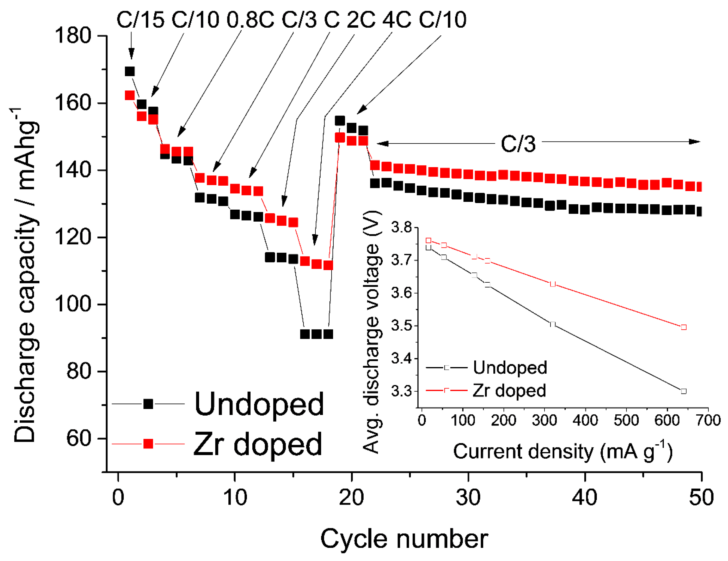
3.1. Zirconium and Aluminum Doping of Li[NixCoyMnz]O2 Materials

Doping of Li[NixCoyMnz]O2 Ni-rich cathode materials with various cations (such as Fe3+, Cu2+, Cr3+, Mg2+, Al3+ and Zr4+) has been reported to enhance their electrochemical behavior [68,96,97,98,99,100,101]. Dopants play various roles in the material. On the one hand, they can act as pillars in the lithium layers and lead to the suppression of c-lattice contraction at the end of the charge, resulting in improved rate capability of the electrode [96]. Furthermore, with dopants occupying lithium sites, the Li+/Ni2+ mixing can be reduced and, hence, the formation of inactive rock salt on the surface is suppressed, resulting in lower charge-transfer-resistance growth with cycling [96,97,102]. Since most of the synthetic strategies of NCM make use of the lithium excess to achieve the correct stoichiometry and minimize the cation mixing during annealing, the material has some excess lithium on the surface. Hence, dopants and surface coatings may react with the surface lithium to form lithium conductive layers [103].
We have recently reported the beneficial impact of zirconium doping in NCM622 [96]. The materials under examination were LiNi0.6Co0.2Mn0.2O2 and LiNi0.54Zr0.04Co0.2Mn0.2O2, synthesized by a self-combustion reaction and annealed at 800 °C under oxygen flow. Based on computational considerations, the Ni2+/Ni3+ ratio was calculated for zirconium doping in place of cobalt, nickel or manganese (Figure 13). Since Zr4+ is electrochemically inactive, doping results in a lower NCM capacity. To compensate for this, Ni was chosen as a substitute, since we have already established the increase in the Ni2+/Ni3+ ratio. With more Ni2+ ions available in the material, the capacity offset induced by the Zr doping can be compensated.
The Zr-doped material exhibits improved performance at higher cycling rates and a more stable capacity over 50 galvanostatic cycles (Figure 14). The improved rate capability is reflected in the impedance behavior with the Zr-doped NCM622, demonstrating responses that are lower by an order of magnitude and less impedance growth during cycling.
Post-cycling analysis by TEM and electron-diffraction studies after 50 cycles of the undoped NCM622 reveal the presence of a spinel-like phase on the surface of the particles (Figure 15a–c). Spinel formation is considered an intermediate step towards the formation of electrochemically inactive rock salt [102]. Among several investigated particles of Zr-doped NCM622, no evidence for spinel formation was found (Figure 15d–f). Some particles show reflections indicative of Li2ZrO3, showcasing the formation of lithium-rich phases on the particles with excess lithium.
Another study was dedicated to investigating the impact of minor aluminum doping (0.01 at %) of the NCM523 material prepared at BASF [97]. According to the synthetic procedure, Al doping took place at the expense of all the transition metals (Ni, Co, Mn). An important motivating factor in this research was to understand the preference of Al doping at Mn, Co or Ni sites, a question which may be addressed by theoretical calculation of the substitution energies. These were calculated for the configurations doped at the preferred Co, Mn and Ni sites as −5.13 −3.10 and −5.86 eV, respectively. Since the highest negative substitution energy of Al is at the Ni sites, Al substitution is preferred there rather than at the Co sites. The thermodynamic preference of Al3+ substitutions follows the order Ni > Co > Mn. The local magnetic moments of undoped LiNi0.5Co0.2Mn0.3O2 suggest that the formal charges on Co and Mn are +3 and +4, respectively. It follows from our calculations that both Ni2+ (magnetic moment ~1.5) and Ni3+ (magnetic moment ~0.8) ions exist in both Al-doped and undoped pristine materials.
Since the NCM523 cathode material is much less problematic (due to a lower Ni-content) than Li-rich NCM622 and NCM811, improvement in the electrochemical performance is usually less obvious. Nonetheless, it was shown that by adding 0.01 at % of Al-dopant to the material, the electrodes demonstrate lower capacity fading (Figure 16).
Interestingly, lower charge transfer and surface-film resistance were measured for the doped material after cycling and aging at 30 °C. This effect is attributed, to some extent, to the formation of LiAlO2 and other species on the surface of the NCM particles. We suggest that a more stable cathode/solution interface and, consequently, lower surface-film and charge-transfer resistance will result from specific surface interactions of these electrodes with solution species. We also suggest that upon cycling or aging in the solutions, a thin reactive surface layer (RSL) on the particles of the Al-doped material becomes enriched with Al3+-ions, which initiate interfacial reactions, such as:
Al3+ + Li+ + 4HF → LiAlF4(s)↓ + 4H+
Al3+ + Li+ + Ni2+ + 3H2O → LiNiAlO3(s)↓ + 6H+
Al3+ + Li+ + 2H2O → LiAlO2(s)↓ + 4H+
It is reasonable to propose that Al-containing species that form in an RSL upon cycling or aging in solutions of Al-doped electrodes may partially suppress the unavoidable formation of LiF, stabilizing the electrode/solution interface and, hence, leading to lower impedance and more stable charge/discharge behavior of these electrodes. Thus, the modified interface comprising the Li+-ion conducting active centers such as LiAlO2, AlF3, Li[AlF4] and others may promote enhanced Li+ transport to the electrode bulk and facilitate the charge-transfer reactions [104].
The higher thermal stability of the Al-doped samples was reflected by the DSC responses of electrodes in the charged state (4.3 V). The heat evolved was calculated as 575 and 520 J·g−1 for undoped NCM523 and Al-doped NCM523, respectively. Since safety is a major concern for commercial application, high capacity materials must be low in heat release. This is especially important for electric-vehicle battery cells of several ampere hours per cell. A failure in one cell can potentially be catastrophic for the whole battery pack. In a recent study by Cho et al., NCM433, NCM523, NCM622 and NCM811 were investigated in terms of thermal stability under charged conditions [105]. The nickel-rich materials NCM811 and NCM622 showed onset temperatures of ~150 and ~200 °C, respectively (Figure 17). Critical failure is accompanied by phase changes from layered to spinel and finally to rock salt. All steps involve gas evolution, which resulted in pressure inside the cell. It is clear that the high capacity and energy of NCM811 is also problematic, and efforts have to be made to ensure sufficient thermal stability by doping and coating approaches.
The increase in the nickel content in NCMs from NCM333 to NCM811 leads to an increase in capacity from ~155 to 195 mAh·g−1. The higher delithiation degree in NCM811 (~70%) is substantial and leads to multiple phase changes during charge and discharge [28,106]. Depletion of the lithium layer is accompanied by a deshielding of the oxygen layers since less and less lithium ions are present. This leads to a stronger repulsive force and hence to an expansion of the c-lattice parameter. With further lithium removal, the emptier lithium layer is likely to be partially filled with transition metals (e.g., Ni) to stabilize the lattice. This leads to strong interactions between high-oxidation-state transition metals inside the lithium layer and the oxygen layers, eventually lowering the c-parameter again (Figure 18). The overall volume change in NCM811 is ~5% if charged to 4.3 V [28]. The rapid c-parameter contraction, starting from 4.1 V, results in a fast volume change of ~2.5% and stress on the phase boundaries of the primary particles. NCM811 and NCM622 are known to form microcracks along the phase boundaries during cycling, leading to an increase in surface areas for side reactions [42].
It should be emphasized that the formation of a reactive surface layer enriched with Al3+ dopant ions, as proposed above, is very important for understanding electrode cycling behavior. This is due to the fact that in the charged electrode some nucleation may be induced starting in RSL to promote the transformation of a layered structure toward a spinel-type structure. This reactive surface layer can also be represented as a “disordered surface layer” surrounding the core of nanoparticles or microparticles of cathode layered-structure materials. It was demonstrated, for instance, that for Li-rich electrodes comprising nano-Li2MnO3 particles, the isothermal magnetization profiles measured by magnetic susceptibility do not differ upon aging the material in EC-DMC/LiPF6 solution, indicating that magnetic transition does not occur (Figure S8) [107]. A decrease in the magnetic moment of the aged nanoparticles shown in Table S2 corresponds to an increase in the reciprocal magnetic susceptibility due to the presence of Mn ions in the low-spin state in a thin disordered layer at the surface of Li2MnO3 particles. This implies that manganese ions are present in a lower oxidation state than 4+: either Mn3+ (S = 1) or Mn2+ (S = ½). Magnetic susceptibility tests have been employed to estimate the amount of these ions [107]. On the basis of the proposed disordered surface layer (DSL) model, it was possible to explain the origin of the observed electrochemical activity of nano-Li2MnO3 electrodes at 4.0–4.1 V that is likely due to reversible oxidation/reduction of Mn3+ and Mn2+ ions from nanoparticles (20–30 nm) with the disordered surface layers of 3–4 nm. The volume of the DSL was estimated to reach ~85%–60%, respective to the total volume of the nanoparticle. One of the main conclusions from this work [107] was that the partial transition of layered Li2MnO3 to a spinel-type structure (confirmed by analysis of XRD, TEM, and Raman spectroscopy studies) occurred in these systems during delithiation/lithiation.

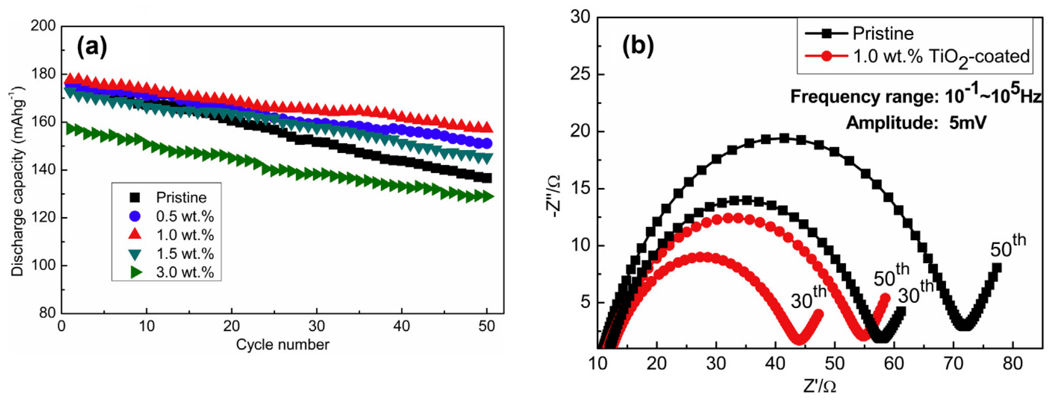
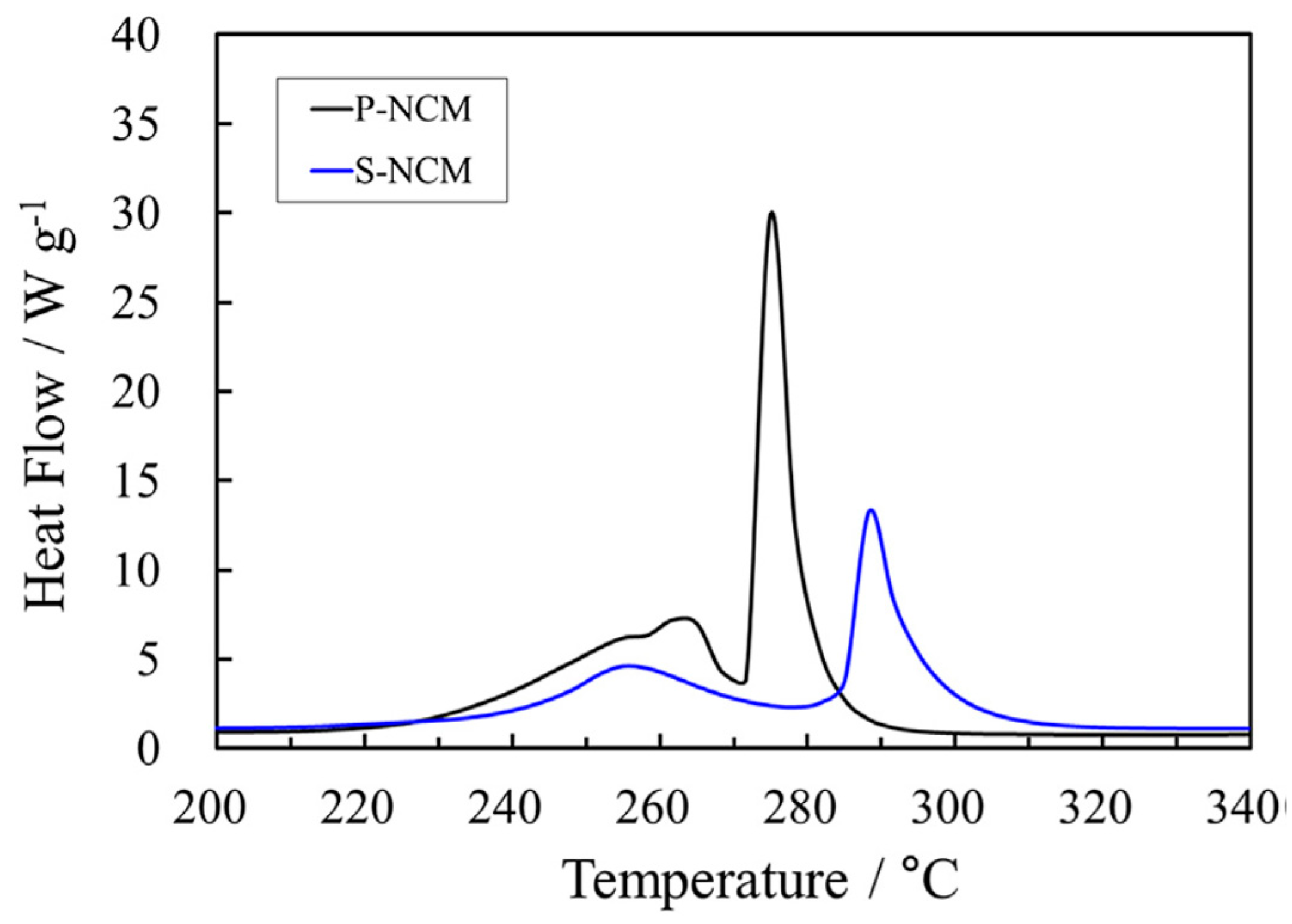
3.2. Surface Coatings of Li[NixCoyMnz]O2 Materials

Set aside from doping strategies, coating cathode materials with thin surface layers is a popular approach to enhance the cycle life and thermal stability of electrodes. The objective is to protect the surface area of the active material by an inert thin layer of organic or inorganic compounds. The coating will act as a barrier between the active material and the electrolyte, minimizing parasitic side reactions at high voltages. In addition, some coatings are known to be HF scavengers, which is especially beneficial if the coating is not uniform or tends to break during cycling [108]. Most of the reported coating strategies employ a wet chemical approach to deposit the coating layer onto the active material, followed by a heat treatment. While this approach is fairly easy to perform, the coatings often suffer from cracks or are deposited as flakes. Recently, powder atomic layer deposition (pALD) was shown to be an alternative technique with several benefits [109]. The coating thickness can be tailored just by the number of pALD cycles and, furthermore, the coating is uniform amongst all secondary particles. An inherent drawback is the still higher cost of the pALD technique.
Numerous coatings have been investigated for different NCMs (e.g., AlF3 [104], Al2O3 [47], ZrO2 [110], TiO2 [111,112], SiO2 [113]). All the coatings were shown to improve the cycle stability of the investigated active material when used in low amounts (Figure 19A). The coatings do not contribute to the electrode capacity, and hence high amounts will lower the specific capacity of the active material [47]. Since side reactions are minimal in coated samples, a lower impedance growth during cycling is usually observed in coated active materials. A 1 wt % TiO2 coating on NCM622 was shown to limit the impedance to 55 Ω in the coated versus 70 Ω in the bare NCM622 after 50 cycles at 30 °C (Figure 19B) [111].
Another property targeted by coatings is the thermal stability of the active material, especially of nickel-rich NCMs. The onset temperature of charged NCM622 (4.3 V) was measured to be ~290 °C, while a 0.5 wt % SiO2 coating could lower the onset to ~270 °C (Figure 20) [113]. It must be emphasized that DSC measurements of charged samples are often run with dry powder, but a more realistic picture would need the addition of the electrolyte solution as well [16]. Nonetheless, trends can also be observed from measurements on dry powder.

4. Conclusions

This paper is a review of recent advances and challenges in the field of materials for positive electrodes (cathodes) of lithium-ion batteries. We focused on two main groups of materials, namely: (1) Li and Mn-rich layered composites of the general formula xLi2MnO3·(1 − x)Li[NiaCobMnc]O2 (a + b + c = 1) that are usually described as comprising two layered structure phases of Li2MnO3 and Li[NiaCobMnc]O2 (a + b + c = 1) integrated on atomic level and existing side by side in the composite, and (2) lithiated transition metal oxides comprising Ni, Co, and Mn and known as Ni-rich Li[NixCoyMnz]O2 layered structure materials (NCM, x > 0.5, x + y + z = 1). Attention was paid to the advantages and drawbacks of the above materials as cathodes in LIBs (especially for EV-applications). It was concluded that during the last decade, the main focus of many research groups has been on modifications of these materials; lattice doping by foreign cations (for instance, Mg2+, Al3+, Zr4+) and thin surface coatings (for instance, prepared by ALD). From numerous literature reports reviewed in this paper, it was established that these modifications resulted in substantial improvement of electrodes’ cycling behavior such as decreasing the capacity fading and the stabilization of the average voltage. Surface coatings also lead to reducing side reactions of cathodes with solution species as well as to increasing their thermal stability in charged states. We also concluded that the fabrication of nanostructured cathode materials with well-defined morphologies, such as porous structures and hollow spheres, is another interesting approach in the field of LIB.
Due to the ever-growing interest of academic researchers and industrial groups in advanced materials for high-energy LIBs, the authors of the present review believe that it will stimulate further investigations in broad aspects related to materials science, electrochemistry, and thermal studies, etc.

Supplementary Materials

The following are available online at www.mdpi.com/2304-6740/5/2/32/s1, Table S1. Literature Survey of Li- and Mn-Rich Porous Cathode Materials for LIBs. Table S2. Magnetic properties of the pristine and two-week aged (in EC-DMC/LiPF6 solution) Li2MnO3 nanostructured samples. Figure S1. A comparison between the capacity, voltage and energy fade of Ni-rich and Li- and Mn-rich materials. Figure S2. XRD pattern of the cycled xLi2MnO3·(1 − x)Li[MnyNizCow]O2/AlF3 material. Figure S3. Schematic view of constructing hybrid surface layers consisting of reduced graphene oxide (rGO) and chemically activated phase on cathode materials. Figure S4. Voltage profiles of PS and HGO cathodes; Rate capabilities measured with increasing C-rates; Cycling performance during 100 cycles. Figure S5. XRD patterns and Rietveld analysis plots of Li1.2Ni0.16Mn0.56−xMgxCo0.08O2. Figure S6. Discharge capacities of electrodes comprising Li,Mn-rich Li1.2Ni0.13Mn0.54Co0.13O2 material prepared by hydrothermal method and Li1.165Mn0.501Ni0.167Co0.167O2 (LMNCO) material prepared by ultrasonic-assisted co-precipitation method. Figure S7. Schematic diagram of the synthesis of porous Li1.2Ni0.13Co0.13Mn0.54O2 (LNCMO) material; The initial charge–discharge curves of the first cycle and rate capability of porous Li1.2Ni0.13Co0.13Mn0.54O2 and bulk Li1.2Ni0.13Co0.13Mn0.54O2 electrode materials. Figure S8. Plot of the reciprocal magnetic susceptibility H/M of the pristine and two-week aged Li2MnO3 nanostructured powders.

Conflicts of Interest

The authors declare no conflict of interest.

References

  1. Goodenough, J.B.; Park, K.-S. The Li-ion rechargeable battery: A perspective. J. Am. Chem. Soc. 2013, 135, 1167–1176. [Google Scholar] [CrossRef] [PubMed]
  2. Etacheri, V.; Marom, R.; Elazari, R.; Salitra, G.; Aurbach, D. Challenges in the development of advanced Li-ion batteries: A review. Energy Environ. Sci. 2011, 4, 3243–3262. [Google Scholar] [CrossRef]
  3. Manthiram, A. Materials challenges and opportunities of lithium ion batteries. J. Phys. Chem. Lett. 2011, 2, 176–184. [Google Scholar] [CrossRef]
  4. Armand, M.; Tarascon, J.-M. Building better batteries. Nature 2008, 451, 652–657. [Google Scholar] [CrossRef] [PubMed]
  5. Thackeray, M.M.; Johnson, C.S.; Vaughey, J.T.; Li, N.; Hackney, S.A. Advances in manganese-oxide ‘composite’ electrodes for lithium-ion batteries. J. Mater. Chem. 2005, 15, 2257–2267. [Google Scholar] [CrossRef]
  6. Erickson, E.M.; Ghanty, C.; Aurbach, D. New horizons for conventional lithium ion battery technology. J. Phys. Chem. Lett. 2014, 5, 3313–3324. [Google Scholar] [CrossRef] [PubMed]
  7. Berg, E.J.; Villevieille, C.; Streich, D.; Trabesinger, S.; Novak, P. Rechargeable batteries: Grasping for the limits of chemistry. J. Electrochem. Soc. 2015, 162, A2468–A2475. [Google Scholar] [CrossRef]
  8. Yan, J.H.; Liu, X.B.; Li, B.Y. Recent progress in Li-rich layered oxides as cathode materials for Li-ion batteries. RSC Adv. 2014, 4, 63268–63284. [Google Scholar] [CrossRef]
  9. Amalraj, F.; Talianker, M.; Markovsky, B.; Sharon, D.; Burlaka, L.; Shafir, G.; Zinigrad, E.; Haik, O.; Aurbach, D.; Lampert, J.; et al. Study of the lithium-rich integrated compound xLi2MnO3·(1 − x)LiMO2 (x around 0.5; M = Mn, Ni, Co; 2:2:1) and its electrochemical activity as positive electrode in lithium cells. J. Electrochem. Soc. 2012, 160, A324–A337. [Google Scholar]
  10. Mohanty, D.; Kalnaus, S.; Meisner, R.A.; Rhodes, K.J.; Li, J.L.; Payzant, E.A.; Wood, D.L.; Daniel, C. Structural transformation of a lithium-rich Li1.2Co0.1Mn0.55Ni0.15O2 cathode during high voltage cycling resolved by in situ X-ray diffraction. J. Power Sources 2013, 229, 239–248. [Google Scholar]
  11. Boulineau, A.; Croguennec, L.; Delmas, C.; Weill, F. Structure of Li2MnO3 with different degrees of defects. Solid State Ion. 2010, 180, 1652–1659. [Google Scholar] [CrossRef]
  12. Shunmugasundaram, R.; Arumugam, R.S.; Dahn, J.R. A study of stacking faults and superlattice ordering in some Li-rich layered transition metal oxide positive electrode materials. J. Electrochem. Soc. 2016, 163, A1394–A1400. [Google Scholar] [CrossRef]
  13. Shukla, A.K.; Ramasse, Q.M.; Ophus, C.; Duncan, H.; Hage, F.; Chen, G. Unravelling structural ambiguities in lithium- and manganese-rich transition metal oxides. Nat Commun. 2015, 6. [Google Scholar] [CrossRef] [PubMed]
  14. Yu, X.; Lyu, Y.; Gu, L.; Wu, H.; Bak, S.-M.; Zhou, Y.; Amine, K.; Ehrlich, S.N.; Li, H.; Nam, K.-W.; et al. Understanding the rate capability of high-energy-density Li-rich layered Li1.2Ni0.15Co0.1Mn0.55O2 cathode materials. Adv. Energy Mater. 2014, 4, 1300950-n/a. [Google Scholar]
  15. Long, B.R.; Croy, J.R.; Dogan, F.; Suchomel, M.R.; Key, B.; Wen, J.; Miller, D.J.; Thackeray, M.M.; Balasubramanian, M. Effect of cooling rates on phase separation in 0.5Li2MnO3·0.5LiCoO2 electrode materials for Li-ion batteries. Chem. Mater. 2014, 26, 3565–3572. [Google Scholar]
  16. Amalraj, F.; Talianker, M.; Markovsky, B.; Burlaka, L.; Leifer, N.; Goobes, G.; Erickson, E.M.; Haik, O.; Grinblat, J.; Zinigrad, E.; et al. Studies of Li and Mn-rich Lix[MnNiCo]O2 electrodes: Electrochemical performance, structure, and the effect of the aluminum fluoride coating. J. Electrochem. Soc. 2013, 160, A2220–A2233. [Google Scholar] [CrossRef]
  17. Liu, Z.; Yu, A.; Lee, J.Y. Synthesis and characterization of LiNi1−xyCoxMnyO2 as the cathode materials of secondary lithium batteries. J. Power Sources 1999, 81–82, 416–419. [Google Scholar]
  18. Yabuuchi, N.; Ohzuku, T. Novel lithium insertion material of LiCo1/3Ni1/3Mn1/3O2 for advanced lithium-ion batteries. J. Power Sources 2003, 119, 171–174. [Google Scholar] [CrossRef]
  19. Ohzuku, T.; Makimura, Y. Layered lithium insertion material of LiCo1/3Ni1/3Mn1/3O2 for lithium-ion batteries. Chem. Lett. 2001, 30, 642–643. [Google Scholar] [CrossRef]
  20. Yabuuchi, N.; Makimura, Y.; Ohzuku, T. Solid-state chemistry and electrochemistry of LiCo1/3Ni1/3Mn1/3O2 for advanced lithium-ion batteries: III. Rechargeable capacity and cycleability. J. Electrochem. Soc. 2007, 154, A314–A321. [Google Scholar] [CrossRef]
  21. Kang, S.H.; Johnson, C.S.; Vaughey, J.T.; Amine, K.; Thackeray, M.M. The effects of acid treatment on the electrochemical properties of 0.5 Li2MnO3·0.5 LiNi0.44Co0.25Mn0.31O2 electrodes in lithium cells. J. Electrochem. Soc. 2006, 153, A1186–A1192. [Google Scholar]
  22. Rossouw, M.H.; Thackeray, M.M. Lithium manganese oxides from Li2MnO3 for rechargeable lithium battery applications. Mater. Res. Bull. 1991, 26, 463–473. [Google Scholar] [CrossRef]
  23. Kalyani, P.; Chitra, S.; Mohan, T.; Gopukumar, S. Lithium metal rechargeable cells using Li2MnO3 as the positive electrode. J. Power Sources 1999, 80, 103–106. [Google Scholar] [CrossRef]
  24. Lu, Z.H.; MacNeil, D.D.; Dahn, J.R. Layered cathode materials Li(NixLi(1/3–2x/3)Mn(2/3−x/3))O2 for lithium-ion batteries. Electrochem. Solid State Lett. 2001, 4, A191–A194. [Google Scholar] [CrossRef]
  25. Koga, H.; Croguennec, L.; Menetrier, M.; Mannessiez, P.; Weill, F.; Delmas, C.; Belin, S. Operando X-ray absorption study of the redox processes involved upon cycling of the Li-rich layered oxide Li1.20Mn0.54Co0.13Ni0.13O2 in li ion batteries. J. Phys. Chem. C 2014, 118, 5700–5709. [Google Scholar]
  26. Kim, T.; Song, B.H.; Lunt, A.J.G.; Cibin, G.; Dent, A.J.; Lu, L.; Korsunsky, A.M. In operando x-ray absorption spectroscopy study of charge rate effects on the atomic environment in graphene-coated Li-rich mixed oxide cathode. Mater. Des. 2016, 98, 231–242. [Google Scholar] [CrossRef]
  27. Fell, C.R.; Chi, M.; Meng, Y.S.; Jones, J.L. In situ x-ray diffraction study of the lithium excess layered oxide compound Li[Li0.2Ni0.2Mn0.6]O2 during electrochemical cycling. Solid State Ion. 2012, 207, 44–49. [Google Scholar]
  28. Li, J.; Shunmugasundaram, R.; Doig, R.; Dahn, J.R. In situ x-ray diffraction study of layered Li–Ni–Mn–Co oxides: Effect of particle size and structural stability of core–shell materials. Chem. Mater. 2016, 28, 162–171. [Google Scholar] [CrossRef]
  29. Abe, M.; Matsumoto, F.; Saito, M.; Yamamura, H.; Kobayashi, G.; Ito, A.; Sanada, T.; Hatano, M.; Ohsawa, Y.; Sato, Y. Activation of a Li-rich solid-solution layered LiNi0.18Li0.20Co0.03Mn0.58O2 cathode and retention of high capacities via an electrochemical pretreatment with a low discharge voltage limit. Chem. Lett. 2012, 41, 418–419. [Google Scholar]
  30. Zheng, J.M.; Xu, P.H.; Gu, M.; Xiao, J.; Browning, N.D.; Yan, P.F.; Wang, C.M.; Zhang, J.G. Structural and chemical evolution of Li- and Mn-rich layered cathode material. Chem. Mater. 2015, 27, 1381–1390. [Google Scholar] [CrossRef]
  31. Nayak, P.K.; Grinblat, J.; Levi, E.; Markovsky, B.; Aurbach, D. Effect of cycling conditions on the electrochemical performance of high capacity Li and Mn-rich cathodes for Li-ion batteries. J. Power Sources 2016, 318, 9–17. [Google Scholar] [CrossRef]
  32. Rana, J.; Kloepsch, R.; Li, J.; Stan, M.; Schumacher, G.; Winter, M.; Banhart, J. Structural changes in a Li-rich 0.5Li2MnO3·0.5LiMn0.4Ni0.4Co0.2O2 cathode material for Li-ion batteries: A local perspective. J. Electrochem. Soc. 2016, 163, A811–A820. [Google Scholar]
  33. Rozier, P.; Tarascon, J.M. Review-Li-rich layered oxide cathodes for next-generation Li-ion batteries: Chances and challenges. J. Electrochem. Soc. 2015, 162, A2490–A2499. [Google Scholar] [CrossRef]
  34. Sathiya, M.; Rousse, G.; Ramesha, K.; Laisa, C.P.; Vezin, H.; Sougrati, M.T.; Doublet, M.L.; Foix, D.; Gonbeau, D.; Walker, W.; et al. Reversible anionic redox chemistry in high-capacity layered-oxide electrodes. Nat. Mater. 2013, 12, 827–835. [Google Scholar] [CrossRef] [PubMed]
  35. McCalla, E.; Abakumov, A.M.; Saubanere, M.; Foix, D.; Berg, E.J.; Rousse, G.; Doublet, M.-L.; Gonbeau, D.; Novak, P.; Van Tendeloo, G.; et al. Visualization of O–O peroxo-like dimers in high-capacity layered oxides for Li-ion batteries. Science 2015, 350, 1516–1521. [Google Scholar] [CrossRef] [PubMed]
  36. Saubanere, M.; McCalla, E.; Tarascon, J.M.; Doublet, M.L. The intriguing question of anionic redox in high-energy density cathodes for Li-ion batteries. Energy Environ. Sci. 2016, 9, 984–991. [Google Scholar] [CrossRef]
  37. Armstrong, A.R.; Dupre, N.; Paterson, A.J.; Grey, C.P.; Bruce, P.G. Combined neutron diffraction, NMR, and electrochemical investigation of the layered-to-spinel transformation in LiMnO2. Chem. Mater. 2004, 16, 3106–3118. [Google Scholar] [CrossRef]
  38. Gallagher, K.G.; Croy, J.R.; Balasubramanian, M.; Bettge, M.; Abraham, D.P.; Burrell, A.K.; Thackeray, M.M. Correlating hysteresis and voltage fade in lithium- and manganese-rich layered transition-metal oxide electrodes. Electrochem. Commun. 2013, 33, 96–98. [Google Scholar] [CrossRef]
  39. Croy, J.R.; Gallagher, K.G.; Balasubramanian, M.; Long, B.R.; Thackeray, M.M. Quantifying hysteresis and voltage fade in xLi2MnO3·(1 − x)LiMn0.5Ni0.5O2 electrodes as a function of Li2MnO3 content. J. Electrochem. Soc. 2014, 161, A318–A325. [Google Scholar]
  40. Dogan, F.; Long, B.R.; Croy, J.R.; Gallagher, K.G.; Iddir, H.; Russell, J.T.; Balasubramanian, M.; Key, B. Re-entrant lithium local environments and defect driven electrochemistry of Li- and Mn-rich Li-ion battery cathodes. J. Am. Chem. Soc. 2015, 137, 2328–2335. [Google Scholar] [CrossRef] [PubMed]
  41. Erickson, E.M.; Schipper, F.; Penki, T.R.; Shin, J.-Y.; Erk, C.; Chesneau, F.-F.; Markovsky, B.; Aurbach, D. Review—recent advances and remaining challenges for lithium ion battery cathodes: Li. Lithium-rich, xLi2MnO3·(1 − x)LiNiaCobMncO2. J. Electrochem. Soc. 2017, 164, A6341–A6348. [Google Scholar] [CrossRef]
  42. Schipper, F.; Erickson, E.M.; Erk, C.; Shin, J.-Y.; Chesneau, F.F.; Aurbach, D. Review—Recent advances and remaining challenges for lithium ion battery cathodes: I. Nickel-rich, LiNixCoyMnzO2. J. Electrochem. Soc. 2017, 164, A6220–A6228. [Google Scholar] [CrossRef]
  43. Freire, M.; Kosova, N.; Jordy, C.; Chateigner, D.; Lebedev, O.; Maignan, A.; Pralong, V. A new active Li-Mn–O compound for high energy density Li-ion batteries. Nat. Mater. 2016, 15, 173–177. [Google Scholar] [CrossRef] [PubMed]
  44. Thackeray, M.; Johnson, C.; Kim, J.-S.; Lauzze, K.; Vaughey, J.; Dietz, N.; Abraham, D.; Hackney, S.; Zeltner, W.; Anderson, M. ZrO2 and Li2ZrO3-stabilized spinel and layered electrodes for lithium batteries. Electrochem. Commun. 2003, 5, 752–758. [Google Scholar] [CrossRef]
  45. Myung, S.-T.; Izumi, K.; Komaba, S.; Yashiro, H.; Bang, H.J.; Sun, Y.-K.; Kumagai, N. Functionality of oxide coating for Li[Li0.05Ni0.4Co0.15Mn0.4]O2 as positive electrode materials for lithium-ion secondary batteries. J. Phys. Chem. C 2007, 111, 4061–4067. [Google Scholar]
  46. Liu, J.; Manthiram, A. Functional surface modifications of a high capacity layered Li[Li0.2Mn0.54Ni0.13Co0.13]O2 cathode. J. Mater. Chem. 2010, 20, 3961–3967. [Google Scholar]
  47. Myung, S.-T.; Izumi, K.; Komaba, S.; Sun, Y.-K.; Yashiro, H.; Kumagai, N. Role of alumina coating on Li–Ni–Co–Mn–O particles as positive electrode material for lithium-ion batteries. Chem. Mater. 2005, 17, 3695–3704. [Google Scholar] [CrossRef]
  48. Zheng, J.; Zhang, Z.; Wu, X.; Dong, Z.; Zhu, Z.; Yang, Y. The effects of ALF3 coating on the performance of Li[Li0.2Mn0.54Ni0.13Co0.13]O2 positive electrode material for lithium-ion battery. J. Electrochem. Soc. 2008, 155, A775–A782. [Google Scholar]
  49. Yun, S.H.; Park, K.-S.; Park, Y.J. The electrochemical property of ZrFx-coated Li[Ni1/3Co1/3Mn1/3]O2 cathode material. J. Power Sources 2010, 195, 6108–6115. [Google Scholar] [CrossRef]
  50. Lee, H.; Kim, Y.; Hong, Y.-S.; Kim, Y.; Kim, M.G.; Shin, N.-S.; Cho, J. Structural characterization of the surface-modified LixNi0.9Co0.1O2 cathode materials by MPO4 coating (M = Al, Ce, Sr, and Fe) for Li-ion cells. J. Electrochem. Soc. 2006, 153, A781–A786. [Google Scholar]
  51. Sun, Y.K.; Lee, M.J.; Yoon, C.S.; Hassoun, J.; Amine, K.; Scrosati, B. The role of AlF3 coatings in improving electrochemical cycling of Li-enriched nickel-manganese oxide electrodes for Li-ion batteries. Adv. Mater. 2012, 24, 1192–1196. [Google Scholar] [CrossRef] [PubMed]
  52. König, R.; Scholz, G.; Scheurell, K.; Heidemann, D.; Buchem, I.; Unger, W.E.S.; Kemnitz, E. Spectroscopic characterization of crystalline AlF3 phases. J. Fluor. Chem. 2010, 131, 91–97. [Google Scholar] [CrossRef]
  53. Amalraj, S.F.; Markovsky, B.; Sharon, D.; Talianker, M.; Zinigrad, E.; Persky, R.; Haik, O.; Grinblat, J.; Lampert, J.; Schulz-Dobrick, M. Study of the electrochemical behavior of the “inactive” Li2MnO3. Electrochim. Acta 2012, 78, 32–39. [Google Scholar] [CrossRef]
  54. Stechert, T.; Rushton, M.; Grimes, R.; Dillon, A. Predicted structure, thermo-mechanical properties and Li ion transport in LiAlF4 glass. J. Non Cryst. Solids 2012, 358, 1917–1923. [Google Scholar] [CrossRef]
  55. Amalraj, F.; Kovacheva, D.; Talianker, M.; Zeiri, L.; Grinblat, J.; Leifer, N.; Goobes, G.; Markovsky, B.; Aurbach, D. Synthesis of integrated cathode materials xLi2MnO3·(1 − x)LiMn1/3Ni1/3Co1/3O2 (x = 0.3, 0.5, 0.7) and studies of their electrochemical behavior. J. Electrochem. Soc. 2010, 157, A1121–A1130. [Google Scholar]
  56. Armstrong, A.; Robertson, A.; Bruce, P. Structural transformation on cycling layered Li(Mn1−yCoy)O2 cathode materials. Electrochim. Acta 1999, 45, 285–294. [Google Scholar] [CrossRef]
  57. Ito, A.; Shoda, K.; Sato, Y.; Hatano, M.; Horie, H.; Ohsawa, Y. Direct observation of the partial formation of a framework structure for Li-rich layered cathode material Li[Ni0.17Li0.2Co0.07Mn0.56]O2 upon the first charge and discharge. J. Power Sources 2011, 196, 4785–4790. [Google Scholar]
  58. Myung, S.-T.; Lee, K.-S.; Yoon, C.S.; Sun, Y.-K.; Amine, K.; Yashiro, H. Effect of ALF3 coating on thermal behavior of chemically delithiated Li0.35[Ni1/3Co1/3Mn1/3]O2. J. Phys. Chem. C 2010, 114, 4710–4718. [Google Scholar]
  59. Kim, J.-H.; Park, M.-S.; Song, J.-H.; Byun, D.-J.; Kim, Y.-J.; Kim, J.-S. Effect of aluminum fluoride coating on the electrochemical and thermal properties of 0.5 Li2MnO3·0.5LiNi0.5Co0.2Mn0.3O2 composite material. J. Alloy. Compd. 2012, 517, 20–25. [Google Scholar]
  60. Sun, Y.-K.; Cho, S.-W.; Lee, S.-W.; Yoon, C.; Amine, K. ALF3-coating to improve high voltage cycling performance of Li[Ni1/3Co1/3Mn1/3]O2 cathode materials for lithium secondary batteries. J. Electrochem. Soc. 2007, 154, A168–A172. [Google Scholar] [CrossRef]
  61. Lee, K.-S.; Myung, S.-T.; Kim, D.-W.; Sun, Y.-K. AlF3-coated LiCoO2 and Li[Ni1/3Co1/3Mn1/3]O2 blend composite cathode for lithium ion batteries. J. Power Sources 2011, 196, 6974–6977. [Google Scholar] [CrossRef]
  62. Liu, W.; Oh, P.; Liu, X.; Myeong, S.; Cho, W.; Cho, J. Countering voltage decay and capacity fading of lithium-rich cathode material at 60 °C by hybrid surface protection layers. Adv. Energy Mater. 2015, 5. [Google Scholar] [CrossRef]
  63. Guan, C.; Wang, J. Recent development of advanced electrode materials by atomic layer deposition for electrochemical energy storage. Adv. Sci. 2016, 3. [Google Scholar] [CrossRef] [PubMed]
  64. Choi, M.; Ham, G.; Jin, B.-S.; Lee, S.-M.; Lee, Y.M.; Wang, G.; Kim, H.-S. Ultra-thin Al2O3 coating on the acid-treated 0.3Li2MnO3·0.7LiMn0.60Ni0.25Co0.15O2 electrode for Li-ion batteries. J. Alloys Compd. 2014, 608, 110–117. [Google Scholar]
  65. Oh, P.; Ko, M.; Myeong, S.; Kim, Y.; Cho, J. A novel surface treatment method and new insight into discharge voltage deterioration for high-performance 0.4Li2MnO3–0.6LiNi1/3Co1/3Mn1/3O2 cathode materials. Adv. Energy Mater. 2014, 4. [Google Scholar] [CrossRef]
  66. Nayak, P.K.; Grinblat, J.; Levi, M.; Markovsky, B.; Aurbach, D. Structural and electrochemical evidence of layered to spinel phase transformation of Li and Mn rich layered cathode materials of the formulae xLi[Li1/3Mn2/3]O2·(1 − x)LiMn1/3Ni1/3Co1/3O2 (x = 0.2, 0.4, 0.6) upon cycling. J. Electrochem. Soc. 2014, 161, A1534–A1547. [Google Scholar]
  67. Qiao, Q.-Q.; Qin, L.; Li, G.-R.; Wang, Y.-L.; Gao, X.-P. Sn-stabilized Li-rich layered Li(Li0.17Ni0.25Mn0.58)O2 oxide as a cathode for advanced lithium-ion batteries. J. Mater. Chem. A 2015, 3, 17627–17634. [Google Scholar]
  68. Wang, D.; Huang, Y.; Huo, Z.; Chen, L. Synthesize and electrochemical characterization of Mg-doped Li-rich layered Li[Li0.2Ni0.2Mn0.6]O2 cathode material. Electrochim. Acta 2013, 107, 461–466. [Google Scholar]
  69. Nayak, P.K.; Grinblat, J.; Levi, M.; Levi, E.; Kim, S.; Choi, J.W.; Aurbach, D. Al doping for mitigating the capacity fading and voltage decay of layered Li and Mn-rich cathodes for Li-ion batteries. Adv. Energy Mater. 2016. [Google Scholar] [CrossRef]
  70. Nayak, P.K.; Grinblat, J.; Levi, E.; Levi, M.; Markovsky, B.; Aurbach, D. Understanding the influence of Mg doping for the stabilization of capacity and higher discharge voltage of Li- and Mn-rich cathodes for Li-ion batteries. Phys. Chem. Chem. Phys. 2017, 19, 6142–6152. [Google Scholar] [CrossRef] [PubMed]
  71. Erickson, E.M.; Schipper, F.; Tian, R.; Shin, J.-Y.; Erk, C.; Chesneau, F.F.; Lampert, J.K.; Markovsky, B.; Aurbach, D. Enhanced capacity and lower mean charge voltage of Li-rich cathodes for lithium ion batteries resulting from low-temperature electrochemical activation. RSC Adv. 2017, 7, 7116–7121. [Google Scholar] [CrossRef]
  72. Vu, A.; Qian, Y.; Stein, A. Porous electrode materials for lithium-ion batteries—How to prepare them and what makes them special. Adv. Energy Mater. 2012, 2, 1056–1085. [Google Scholar] [CrossRef]
  73. Yang, X.-Y.; Li, Y.; Lemaire, A.; Yu, J.-G.; Su, B.-L. Hierarchically structured functional materials: Synthesis strategies for multimodal porous networks. Pure Appl. Chem. 2009, 81, 2265–2307. [Google Scholar] [CrossRef]
  74. Zhang, L.; Borong, W.; Ning, L.; Feng, W. Hierarchically porous micro-rod lithium-rich cathode material Li1.2Ni0.13Mn0.54Co0.13O2 for high performance lithium-ion batteries. Electrochim. Acta 2014, 118, 67–74. [Google Scholar]
  75. Ma, S.; Hou, X.; Li, Y.; Ru, Q.; Hu, S.; Lam, K.-H. Performance and mechanism research of hierarchically structured Li-rich cathode materials for advanced lithium-ion batteries. J. Mater. Sci.. Mater. Electron. 2017, 28, 2705–2715. [Google Scholar] [CrossRef]
  76. Duraisamy, S.; Penki, T.R.; Nookala, M. Hierarchically porous Li1.2Mn0.6Ni0.2O2 as a high capacity and high rate capability positive electrode material. New J. Chem. 2016, 40, 1312–1322. [Google Scholar]
  77. Penki, T.R.; Shanmughasundaram, D.; Jeyaseelan, A.; Subramani, A.; Munichandraiah, N. Polymer template assisted synthesis of porous Li1.2Mn0.53Ni0.13Co0.13O2 as a high capacity and high rate capability positive electrode material. J. Electrochem. Soc. 2014, 161, A33–A39. [Google Scholar]
  78. Penki, T.R.; Shanmughasundaram, D.; Kishore, B.; Jeyaseelan, A.; Subramani, A.; Munichandraiah, N. Composite of Li-rich Mn, Ni and Fe oxides as positive electrode materials for Li-ion battery. J. Electrochem. Soc. 2016, 163, A1493–A1502. [Google Scholar] [CrossRef]
  79. Penki, T.R.; Shanmughasundaram, D.; Munichandraiah, N. Porous lithium rich Li1.2Mn0.54Ni0.22Fe0.04O2 prepared by microemulsion route as a high capacity and high rate capability positive electrode material. Electrochim. Acta 2014, 143, 152–160. [Google Scholar]
  80. Boutonnet, M.; Kizling, J.; Stenius, P.; Maire, G. The preparation of monodisperse colloidal metal particles from microemulsions. Coll. Surf. 1982, 5, 209–225. [Google Scholar] [CrossRef]
  81. Kleitz, F.; Choi, S.H.; Ryoo, R. Cubic ia 3D large mesoporous silica: Synthesis and replication to platinum nanowires, carbon nanorods and carbon nanotubes. Chem. Commun. 2003, 17, 2136–2137. [Google Scholar] [CrossRef]
  82. Chen, M.; Xiang, X.; Chen, D.; Liao, Y.; Huang, Q.; Li, W. Polyethylene glycol-assisted synthesis of hierarchically porous layered lithium-rich oxide as cathode of lithium ion battery. J. Power Sources 2015, 279, 197–204. [Google Scholar] [CrossRef]
  83. Li, Q.; Li, G.; Fu, C.; Luo, D.; Fan, J.; Li, L. K+-doped Li1.2Mn0.54Co0.13Ni0.13O2: A novel cathode material with an enhanced cycling stability for lithium-ion batteries. ACS Appl. Mater. Interf. 2014, 6, 10330–10341. [Google Scholar]
  84. Song, B.; Liu, H.; Liu, Z.; Xiao, P.; Lai, M.O.; Lu, L. High rate capability caused by surface cubic spinels in Li-rich layer-structured cathodes for Li-ion batteries. Sci. Rep. 2013, 3, 3094. [Google Scholar] [CrossRef] [PubMed]
  85. Gu, M.; Belharouak, I.; Zheng, J.; Wu, H.; Xiao, J.; Genc, A.; Amine, K.; Thevuthasan, S.; Baer, D.R.; Zhang, J.-G. Formation of the spinel phase in the layered composite cathode used in Li-ion batteries. ACS Nano 2012, 7, 760–767. [Google Scholar] [CrossRef] [PubMed]
  86. Xu, B.; Fell, C.R.; Chi, M.; Meng, Y.S. Identifying surface structural changes in layered Li-excess nickel manganese oxides in high voltage lithium ion batteries: A joint experimental and theoretical study. Energy Environ. Sci. 2011, 4, 2223–2233. [Google Scholar] [CrossRef]
  87. Zheng, J.; Gu, M.; Genc, A.; Xiao, J.; Xu, P.; Chen, X.; Zhu, Z.; Zhao, W.; Pullan, L.; Wang, C. Mitigating voltage fade in cathode materials by improving the atomic level uniformity of elemental distribution. Nano Lett. 2014, 14, 2628–2635. [Google Scholar] [CrossRef] [PubMed]
  88. Zheng, J.; Gu, M.; Xiao, J.; Zuo, P.; Wang, C.; Zhang, J.-G. Corrosion/fragmentation of layered composite cathode and related capacity/voltage fading during cycling process. Nano Lett. 2013, 13, 3824–3830. [Google Scholar] [CrossRef] [PubMed]
  89. Jiang, Y.; Zhuang, H.; Ma, Q.; Jiao, Z.; Zhang, H.; Liu, R.; Chu, Y.; Zhao, B. Synthesis of porous Li2MnO3-LiNi1/3Co1/3Mn1/3O2 nanoplates via colloidal crystal template. J. Mater. Res. 2013, 28, 1505–1511. [Google Scholar] [CrossRef]
  90. Zhang, L.; Jiang, J.; Zhang, C.; Wu, B.; Wu, F. High-rate layered lithium-rich cathode nanomaterials for lithium-ion batteries synthesized with the assist of carbon spheres templates. J. Power Sources 2016, 331, 247–257. [Google Scholar] [CrossRef]
  91. Jiang, Y.; Yang, Z.; Luo, W.; Hu, X.; Huang, Y. Hollow 0.3Li2MnO3·0.7LiNi0.5Mn0.5O2 microspheres as a high-performance cathode material for lithium–ion batteries. Phys. Chem. Chem. Phys. 2013, 15, 2954–2960. [Google Scholar]
  92. Wei, C.; Deng, J.; Xi, L.; Zhou, H.; Wang, Z.; Chung, C.Y.; Yao, Q.; Rao, G. High power LiMn2O4 hollow microsphere cathode materials for lithium ion batteries. Int. J. Electrochem. Sci. 2013, 8, 6775–6783. [Google Scholar]
  93. Duraisamy, S.; Penki, T.R.; Kishore, B.; Barpanda, P.; Nayak, P.K.; Aurbach, D.; Munichandraiah, N. Porous, hollow Li1.2Mn0.53Ni0.13Co0.13O2 microspheres as a positive electrode material for Li-ion batteries. J. Solid State Electrochem. 2017, 21, 437–445. [Google Scholar]
  94. Hu, Y.S.; Adelhelm, P.; Smarsly, B.M.; Hore, S.; Antonietti, M.; Maier, J. Synthesis of hierarchically porous carbon monoliths with highly ordered microstructure and their application in rechargeable lithium batteries with high-rate capability. Adv. Funct. Mater. 2007, 17, 1873–1878. [Google Scholar] [CrossRef]
  95. Sinha, N.N.; Shivakumara, C.; Munichandraiah, N. High rate capability of a dual-porosity LiFePO4/C composite. ACS Appl. Mater. Interf. 2010, 2, 2031–2038. [Google Scholar] [CrossRef]
  96. Schipper, F.; Dixit, M.; Kovacheva, D.; Talianker, M.; Haik, O.; Grinblat, J.; Erickson, E.M.; Ghanty, C.; Major, D.T.; Markovsky, B.; et al. Stabilizing nickel-rich layered cathode materials by a high-charge cation doping strategy: Zirconium-doped LiNi0.6Co0.2Mn0.2O2. J. Mater. Chem. A 2016, 4, 16073–16084. [Google Scholar] [CrossRef]
  97. Aurbach, D.; Srur-Lavi, O.; Ghanty, C.; Dixit, M.; Haik, O.; Talianker, M.; Grinblat, Y.; Leifer, N.; Lavi, R.; Major, D.T.; et al. Studies of aluminum-doped LiNi0.5Co0.2Mn0.3O2: Electrochemical behavior, aging, structural transformations, and thermal characteristics. J. Electrochem. Soc. 2015, 162, A1014–A1027. [Google Scholar]
  98. Jin, X.; Xu, Q.; Liu, H.; Yuan, X.; Xia, Y. Excellent rate capability of Mg doped Li[Li0.2Ni0.13Co0.13Mn0.54]O2 cathode material for lithium-ion battery. Electrochim. Acta 2014, 136, 19–26. [Google Scholar]
  99. Liu, L.; Sun, K.N.; Zhang, N.Q.; Yang, T.Y. Improvement of high-voltage cycling behavior of Li(Ni1/3Co1/3Mn1/3)O2 cathodes by Mg, Cr, and Al substitution. J. Solid State Electrochem. 2009, 13, 1381–1386. [Google Scholar] [CrossRef]
  100. Liu, D.T.; Wang, Z.X.; Chen, L.Q. Comparison of structure and electrochemistry of Al- and Fe-doped LiNi1/3Co1/3Mn1/3O2. Electrochim. Acta 2006, 51, 4199–4203. [Google Scholar] [CrossRef]
  101. Chen, C.H.; Liu, J.; Stoll, M.E.; Henriksen, G.; Vissers, D.R.; Amine, K. Aluminum-doped lithium nickel cobalt oxide electrodes for high-power lithium-ion batteries. J. Power Sources 2004, 128, 278–285. [Google Scholar] [CrossRef]
  102. Jung, S.-K.; Gwon, H.; Hong, J.; Park, K.-Y.; Seo, D.-H.; Kim, H.; Hyun, J.; Yang, W.; Kang, K. Understanding the degradation mechanisms of LiNi0.5Co0.2Mn0.3O2 cathode material in lithium ion batteries. Adv. Energy Mater. 2014, 4, 1300787-n/a. [Google Scholar]
  103. Shin, D.W.; Bridges, C.A.; Huq, A.; Paranthaman, M.P.; Manthiram, A. Role of cation ordering and surface segregation in high-voltage spinel LiMn1.5Ni0.5–xMxO4 (M = Cr, Fe, and Ga) cathodes for lithium-ion batteries. Chem. Mater. 2012, 24, 3720–3731. [Google Scholar]
  104. Park, B.C.; Kim, H.B.; Myung, S.T.; Amine, K.; Belharouak, I.; Lee, S.M.; Sun, Y.K. Improvement of structural and electrochemical properties of AlF3-coated Li[Ni1/3Co1/3Mn1/3]O2 cathode materials on high voltage region. J. Power Sources 2008, 178, 826–831. [Google Scholar] [CrossRef]
  105. Bak, S.-M.; Hu, E.; Zhou, Y.; Yu, X.; Senanayake, S.D.; Cho, S.-J.; Kim, K.-B.; Chung, K.Y.; Yang, X.-Q.; Nam, K.-W. Structural changes and thermal stability of charged LiNixMnyCozO2 cathode materials studied by combined in situ time-resolved XRD and mass spectroscopy. ACS Appl. Mater. Interf. 2014, 6, 22594–22601. [Google Scholar] [CrossRef] [PubMed]
  106. Ghanty, C.; Markovsky, B.; Erickson, E.M.; Talianker, M.; Haik, O.; Tal-Yossef, Y.; Mor, A.; Aurbach, D.; Lampert, J.; Volkov, A.; et al. Li+-ion extraction/insertion of Ni-rich Li1+x(NiyCozMnz)wO2 (0.005 <x <0.03; y:z=8:1, w ≈ 1) electrodes: Insitu XRD and raman spectroscopy study. ChemElectroChem 2015, 2, 1479–1486. [Google Scholar]
  107. Amalraj, S.F.; Sharon, D.; Talianker, M.; Julien, C.M.; Burlaka, L.; Lavi, R.; Zhecheva, E.; Markovsky, B.; Zinigrad, E.; Kovacheva, D. Study of the nanosized Li2MnO3: Electrochemical behavior, structure, magnetic properties, and vibrational modes. Electrochim. Acta 2013, 97, 259–270. [Google Scholar] [CrossRef]
  108. Chen, Z.; Qin, Y.; Amine, K.; Sun, Y.K. Role of surface coating on cathode materials for lithium-ion batteries. J. Mater. Chem. 2010, 20, 7606–7612. [Google Scholar] [CrossRef]
  109. Li, X.; Liu, J.; Meng, X.; Tang, Y.; Banis, M.N.; Yang, J.; Hu, Y.; Li, R.; Cai, M.; Sun, X. Significant impact on cathode performance of lithium-ion batteries by precisely controlled metal oxide nanocoatings via atomic layer deposition. J. Power Sources 2014, 247, 57–69. [Google Scholar] [CrossRef]
  110. Ghanty, C.; Dahiya, P.P.; Basu, R.N.; Chang, J.-K.; Majumder, S.B. Improvement of the electrochemical characteristics of lithium and manganese rich layered cathode materials: Effect of surface coating. J. Electrochem. Soc. 2015, 162, A1957–A1965. [Google Scholar] [CrossRef]
  111. Chen, Y.; Zhang, Y.; Chen, B.; Wang, Z.; Lu, C. An approach to application for LiNi0.6Co0.2Mn0.2O2 cathode material at high cutoff voltage by TiO2 coating. J. Power Sources 2014, 256, 20–27. [Google Scholar]
  112. Qin, C.; Cao, J.; Chen, J.; Dai, G.; Wu, T.; Chen, Y.; Tang, Y.; Li, A.; Chen, Y. Improvement of electrochemical performance of nickel rich LiNi0.6Co0.2Mn0.2O2 cathode active material by ultrathin TiO2 coating. Dalton Trans. 2016, 45, 9669–9675. [Google Scholar] [PubMed]
  113. Cho, W.; Kim, S.-M.; Song, J.H.; Yim, T.; Woo, S.-G.; Lee, K.-W.; Kim, J.-S.; Kim, Y.-J. Improved electrochemical and thermal properties of nickel rich LiNi0.6Co0.2Mn0.2O2 cathode materials by SiO2 coating. J. Power Sources 2015, 282, 45–50. [Google Scholar]
Figure 1. (A) Charge and (B) dQ/dV profiles for the first cycle of a representative Li-rich 0.35LiMn2O3·0.65Li[Mn0.45Ni0.35Co0.20]O2 electrode in a Li-cell at a rate of C/20, 30 °C. Modified from [41].
Inorganics 05 00032 g001
Figure 2. HRTEM image of the xLi2MnO3·(1 − x)Li[MnyNizCow]O2 (x around 0.5, y:z:w around 2:2:1) pristine material coated with AlF3. Inset (a) is the Fourier transform of the image in a square marked by A. Subscripts (m) and (t) of the indexed spots are related to the monoclinic Li2MnO3 and tetragonal t-AlF3 phases, respectively; Inset (b) shows a filtered image of the AlF3 coating layer; Inset (a) exhibits a superposition of two sets of reflection spots, Li2MnO3 and t-AlF3; Inset (b) demonstrates a filtered image of the AlF3 structure with distances of 0.36, 0.39 and 0.31 nm between lattice fringes, which match the interplanar spacing d220, d211 and d301 in the t-AlF3 phase, respectively; Inset (c) is a TEM micrograph showing the microstructure of the xLi2MnO3·(1 − x)Li[MnyNizCow]O2 pristine material coated with AlF3. CBED patterns (a) and (b) are indexed on the basis of the monoclinic Li2MnO3 and tetragonal AlF3 structures, respectively. The layers of AlF3 are indicated by arrows. The coating crystallizes into the tetragonal structure t-AlF3 described by the P4nmm symmetry, possessing a unit cell with the parameters a = 10.1843 Å and c = 7.1738 Å. Reprinted from [16].
Inorganics 05 00032 g002
Figure 3. Charge/discharge cycling behavior at 60 °C of the uncoated xLi2MnO3·(1 − x)Li[MnyNizCow]O2 (x around 0.5, y:z:w around 2:2:1) electrode (a) and of a similar electrode comprising AlF3 coated material (b); Mean voltage of these electrodes registered in charge and in discharge as a function of cycle number (c). Reprinted from [16].
Inorganics 05 00032 g003
Figure 4. Typical DSC responses measured upon heating. In chart (A) (a) 1M LiPF6/ EC:DMC 1:1 electrolyte solution, (bd) uncoated and AlF3-coated xLi2MnO3·(1 − x)Li[MnyNizCow]O2 (x around 0.5, y:z:w around 2:2:1) materials in the same solution: (b) pristine uncoated electrode, (c) pristine AlF3-coated electrode, (d) uncoated charged electrode (delithiated state) after 20th cycle at 60 °C. In chart (B) AlF3-coated charged electrode (delithiated state) after 20th cycle at 60 °C. Reprinted from [16].
Inorganics 05 00032 g004
Figure 5. Design of surface-coated high-energy cathode material with a LiMgPO4 protecting layer. (a) Schematic illustration of surface-modified Li-rich cathode particles with the novel hybrid material LiMgPO4; (b) Schematic diagram showing the preparation of surface-coated Li1.17Ni0.17Co0.17Mn0.5O2 particles from bare material. Reprinted with permission [62]. Copyright 2015, Wiley-VCH Verlag.
Inorganics 05 00032 g005
Figure 6. Electrochemical performance of the bare and surface-coated Li- and Mn-rich cathode materials at 60 °C. (a) The discharge capacity versus prolonged cycling of the bare and 1.5 wt % coated samples at 60 °C at a 1.0 C/1.0 C rate after several formation cycles; (b,c) The charge/discharge profiles of the bare and 1.5 wt % surface-modified Li-rich cathode materials. Reprinted with permission [62]. Copyright 2015, Wiley-VCH Verlag.
Inorganics 05 00032 g006
Figure 7. Voltage profiles measured from selected cycles (as indicated) of Li1.2Ni0.16Mn0.56−xMgxCo0.08O2 (x = 0.00 (a) 0.02 (b), 0.05 (c)) cathodes cycled galvanostatically at 20 mA·g−1 (C/10 rate). The potential range is 2.0–4.6 V. Coin-type cells, 1 M LiPF6 in EC:DMC (1:1) solutions. Reprinted from [70].
Inorganics 05 00032 g007
Figure 8. Specific capacity as a function of cycle number, measured from undoped (i) Li1.2Ni0.16Mn0.56Co0.08O2, Mg-doped (ii) Li1.2Ni0.16Mn0.54Mg0.02Co0.08O2 and (iii) Li1.2Ni0.16Mn0.51Mg0.05Co0.08O2 electrodes at 30° C. The first cycle was carried out at 4.7 V and the rest were carried out over the potential range of 2.0–4.6 V, at a rate of C/10. Empty and filled symbols stand for charge and discharge capacities, respectively. Coin-type cells, EC-DMC/1M LiPF6 solutions. Reprinted from [70].
Inorganics 05 00032 g008
Figure 9. Low-temperature activation of electrodes comprising different compositions of Li- and Mn-rich materials. 0.35Li2MnO3·0.65Li[Mn0.45Ni0.35Co0.20]O2 cycled at (A) 30 and (B) 45 °C after the first two cycles, which were performed at 0–45 °C as indicated. Reprinted from Erickson et al. with permission [71]; (C) 0.75Li2MnO3·0.25Li[Mn0.45Ni0.35Co0.20]O2 cycled at 30 °C after the first two cycles, which were performed at 0 and 30 °C as indicated. Modified from [41].
Inorganics 05 00032 g009
Figure 10. (a) Schematic diagram of the inverse micro-emulsion route using a tri-block co-polymer as a soft template for producing electrode materials; (b) SEM image of 0.5Li2MnO3·0.5LiMn1/3Ni1/3Co1/3O2 sample heated to 900 °C; (c) pore-size-distribution (BJH) curves of 0.5Li2MnO3·0.5LiMn1/3Ni1/3Co1/3O2 samples heated to 500, 600, 700, 800 and 900 °C (in the inset), as indicated; and (d) rate capability of 0.5Li2MnO3·0.5LiMn1/3Ni1/3Co1/3O2 electrode samples heated to 800 °C (i) and 900 °C (ii). Reprinted from [77].
Inorganics 05 00032 g010
Figure 11. Typical discharge curves and corresponding differential capacity curves of 0.5Li2MnO3·0.5LiMn1/3Ni1/3Co1/3O2 (A,B) and PEG2000-0.5Li2MnO3·0.5LiMn1/3Ni1/3Co1/3O2 (C,D) electrodes cycled between 2.0 and 4.8 V at 0.2 C (50 mA·g−1). Reprinted with permission [82]. Copyright 2015, Elsevier.
Inorganics 05 00032 g011
Figure 12. (a) Schematic illustration of the formation of hollow Li-rich materials; (b,c) SEM and TEM images of hollow Li-rich Li1.2Mn0.54Ni0.13Co0.13O2 material; (d) Rate capability of Li1.2Mn0.54Ni0.13Co0.13O2 electrode sample, current densities (mA·g−1) are indicated; (e) A comparison of the rate capabilities of electrodes comprising hollow microspheres, nanoparticles and bulk 0.3Li2MnO3·0.7LiNi0.5Mn0.5O2 materials. Reprinted with permission [89,93]. Copyright 2017, Springer, and 2013, Royal Society of Chemistry.
Inorganics 05 00032 g012
Figure 13. Oxidation states of transition metals in undoped and doped NCM-622 with Zr. Reprinted from [96].
Inorganics 05 00032 g013
Figure 14. Galvanostatic cycling of LiNi0.6Co0.2Mn0.2O2 and LiNi0.54Zr0.04Co0.2Mn0.2O2 under various C rates at 45 °C (1 C rate: 160 mAh·g−1). Reprinted from [96].
Inorganics 05 00032 g014
Figure 15. (ac) TEM image and electron diffraction patterns of undoped NCM622 after 50 cycles at 45 °C. Spinel-like structure species were found on the surface; (df) Electron-diffraction patterns of Zr-doped NCM622 after 50 cycles at 45 °C. No indication of spinel was found, among several investigated particles. The formation of Li2ZrO3 was confirmed in small amounts. Reprinted from [96].
Inorganics 05 00032 g015
Figure 16. Cycle stability of NCM523 (a) and Al-doped NCM523 (b) at 30 °C. The cycling rate was C/15 for the initial cycles and C/5 for the rest. Reprinted from [97].
Inorganics 05 00032 g016
Figure 17. Pressure diagram for NCM433, NCM523, NCM622 and NCM811 electrodes over a wide temperature range and the accompanying phase changes; all measurements were made for charged materials without any addition of electrolyte solution. Reprinted from [105].
Inorganics 05 00032 g017
Figure 18. (a) Lattice parameter changes in NCM811 electrode during charge and discharge measured by in situ XRD; (b) dQ/dV profile for NCM811. Reprinted with permission [106]. Copyright 2015, Wiley.
Inorganics 05 00032 g018
Figure 19. (a) Cycle stability of NCM622 material coated with various amounts of TiO2 at 30 °C, cycled in the potential range of 3–4.5 V; (b) Impedance spectra for pristine and 1 wt % TiO2-coated NCM622 after 30 and 50 cycles. Reprinted with permission [111]. Copyright 2014, Elsevier.
Inorganics 05 00032 g019
Figure 20. DSC measurement of charged pristine NCM622 (P-NCM) and 0.5 wt % SiO2-coated NCM622 (S-NCM) charged to 4.3 V. Reprinted with permission [113]. Copyright 2015, Elsevier.
Inorganics 05 00032 g020

